

Burkert 8325 Operating Instructions Manual
Operating Instructions
Bedienungsanleitung
Manuel d‘utilisation
EN
DE
FR
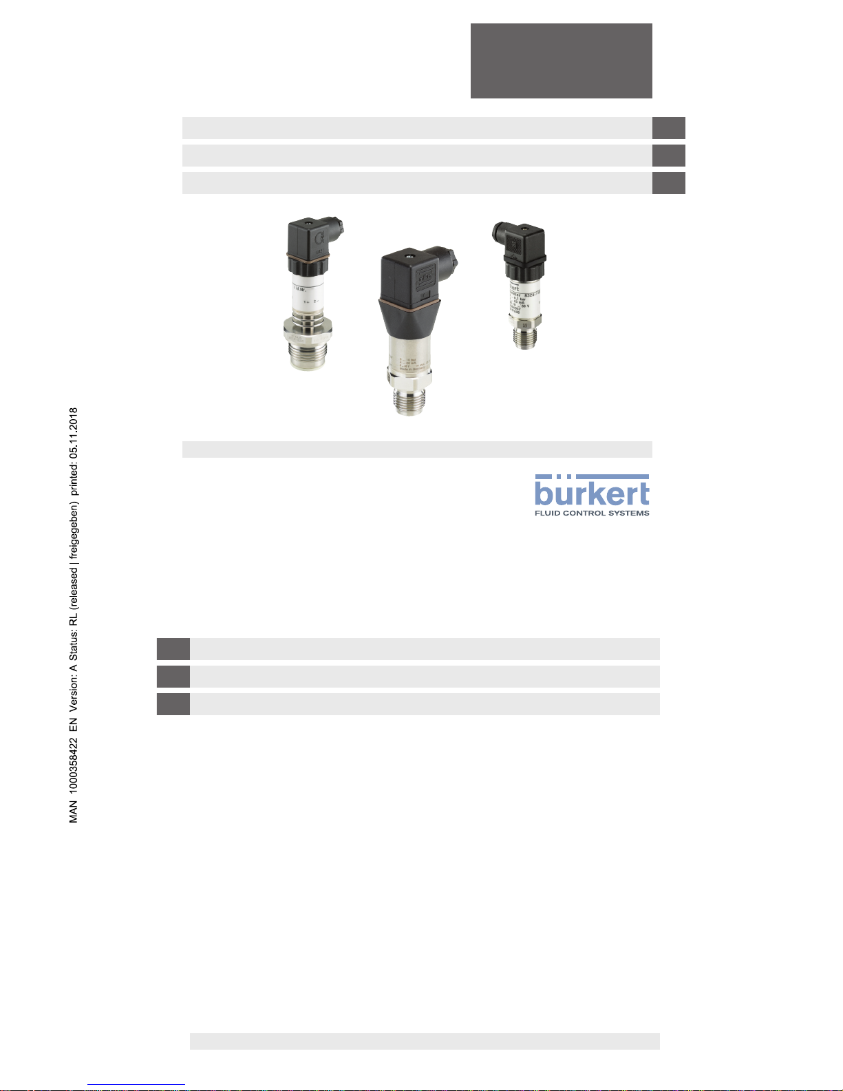
Pressure transmitter Type 8325
Drucktransmitter Typ 8325
Pressure transmitter Type 8325
Transmetteur de pression type 8325
2
Bürkert Operating Instructions - Pressure transmitter Type 8325
EN
DE
FR
Operating Instructions Type 8325
Page 3 - 38
Bedienungsanleitung
Typ 8325
Seite 39 - 74
Manuel d’utilisation type
8325
Page 75 - 112
We reserve the right to make technical changes without notice.
Technische Änderungen vorbehalten.
Sous réserve de modication technique.
Operating Instructions 1811/01_EU-ML / Original_EN
14311508.01
Prior to starting any work, read the Operating Instructions!
Keep for later use!
Vor Beginn aller Arbeiten Bedienungsanleitung lesen!
Zum späteren Gebrauch aufbewahren!
Lire le manuel d‘utilisation avant de commencer toute opération !
A conserver pour une utilisation ultérieure !
3
Bürkert Operating Instructions - Pressure transmitter Type 8325
EN
Contents
1. General information 5
2. Safety 7
3. Labelling / safety marks 9
4. Specications of the transmitter 8325-S, ≥ 0,4 bar 10
5. Specications of the transmitter 8325-F, ush diaphragm 16
6. Specications of the transmitter 8325-L, < 0,4 bar 21
7. Design and function 24
8. Transport, packaging and storage 24
9. Commissioning, operation 26
10. Zero point adjustment and span 32
11. Maintenance and cleaning 34
12. Faults 35
13. Dismounting, return and disposal 37
14. Accessories for the transmitter 8325-F, ush diaphragm 38
4
Bürkert Operating Instructions - Pressure transmitter Type 8325
EN
15. Declaration of conformity 38
5
Bürkert Operating Instructions - Pressure transmitter Type 8325
EN
1. General information
1. General information
■
The transmitter described in the Operating Instructions has been designed and manufactured using state-of-the-art
technology.
All components are subject to stringent quality and environmental criteria during production.
■
These Operating Instructions contain important information on handling the instrument. Working safely requires that
all safety instructions and work instructions are observed.
■
Observe the relevant local accident prevention regulations and general safety regulations for the instrument's range
of use.
■
The Operating Instructions are part of the product and must be kept in the immediate vicinity of the instrument and
readily accessible to skilled personnel at any time.
Pass the Operating Instructions onto the next operator or owner of the instrument.
■
Skilled personnel must have carefully read and understood the Operating Instructions prior to beginning any work.
■
The manufacturer's liability is void in the event of any damage caused by using the product contrary to its intended
use, non-compliance with these Operating Instructions, assignment of insuciently qualied skilled personnel or
unauthorised modications to the instrument.
■
The general terms and conditions contained in the sales documentation shall apply.
■
Subject to technical modications.
■
Further information:
Contact your local Bürkert sales oce.
The addresses of our international sales oces are available on the internet at: www.burkert.com
6
Bürkert Operating Instructions - Pressure transmitter Type 8325
EN
Explanation of symbols
WARNING!
... indicates a potentially dangerous situation that can result in serious injury or death, if not avoided.
CAUTION!
... indicates a potentially dangerous situation that can result in light injuries or damage to the equipment or
the environment, if not avoided.
Information
... points out useful tips, recommendations and information for ecient and trouble-free operation.
WARNING!
... indicates a potentially dangerous situation that can result in burns, caused by hot surfaces or liquids, if
not avoided.
Abbreviations
2-wire The two connection lines are used for the voltage supply.
The measurement signal also provides the supply current.
3-wire Two connection lines are used for the power supply.
One connection line is used for the measurement signal.
U+ Positive power supply terminal
U– Negative power supply terminal
S+ Positive output terminal
1. General information
7
Bürkert Operating Instructions - Pressure transmitter Type 8325
EN
2. Safety
WARNING!
Before installation, commissioning and operation, ensure that the appropriate transmitter has been selected
in terms of measuring range, design and specic measuring conditions.
Non-observance can result in serious injury and/or damage to the equipment.
WARNING!
■
Open the connections only after the system has been depressurised.
■
Observe the working conditions in accordance with chapters 4, 5 and 6.
■
Always operate the transmitter within the overpressure limit.
WARNING!
Risk of burn injury due to high uid temperatures
■
Do not touch with bare hands the parts of the device that are in contact with the uid.
■
Use safety gloves to handle the device.
■
Before opening the pipe, stop the circulation of uid and drain the pipe.
■
Before opening the pipe, make sure the pipe is completely empty.
Further important safety instructions can be found in the individual chapters of these Operating Instructions.
2.1 Intended use
The transmitter is used to convert pressure into an electrical signal indoors and outdoors.
For applications with direct contact with foodstus, only use the transmitter 8325-F, ush diaphragm.
Only use the transmitter in applications that lie within its technical performance limits (e.g. max. ambient temperature,
material compatibility, ...).
The instrument has been designed and built solely for the intended use described here, and may only be used
accordingly.
The technical specications contained in these Operating Instructions must be observed. Improper handling or operation of the transmitter outside of its technical specications requires the instrument to be taken out of service immedi-
ately and inspected by an authorised Bürkert service engineer.
The manufacturer shall not be liable for claims of any type based on operation contrary to the intended use.
2. Safety
8
Bürkert Operating Instructions - Pressure transmitter Type 8325
EN
2.2 Personnel qualication
WARNING!
Risk of injury should qualication be insucient!
Improper handling can result in considerable injury and damage to equipment.
The activities described in these Operating Instructions may only be carried out by skilled personnel who
have the qualications described below.
Skilled personnel
Skilled personnel are understood to be personnel who, based on their technical training, knowledge of measurement
and control technology and on their experience and knowledge of country-specic regulations, current standards and
directives, are capable of carrying out the work described and independently recognising potential hazards.
Special operating conditions require further appropriate knowledge, e.g. of aggressive media.
2.3 Special hazards
WARNING!
For hazardous media such as oxygen, acetylene, ammable or toxic gases or liquids, and refrigeration
plants, compressors, etc., in addition to all standard regulations, the appropriate existing codes or
regulations must also be followed.
WARNING!
Residual media in dismounted transmitters can result in a risk to persons, the environment and equipment.
Take sucient precautionary measures.
Do not use this instrument in safety or emergency stop devices. Incorrect use of the instrument can result in injury.
Should a failure occur, aggressive media with extremely high temperature and under high pressure or vacuum may
be present at the instrument.
2. Safety
9
Bürkert Operating Instructions - Pressure transmitter Type 8325
EN
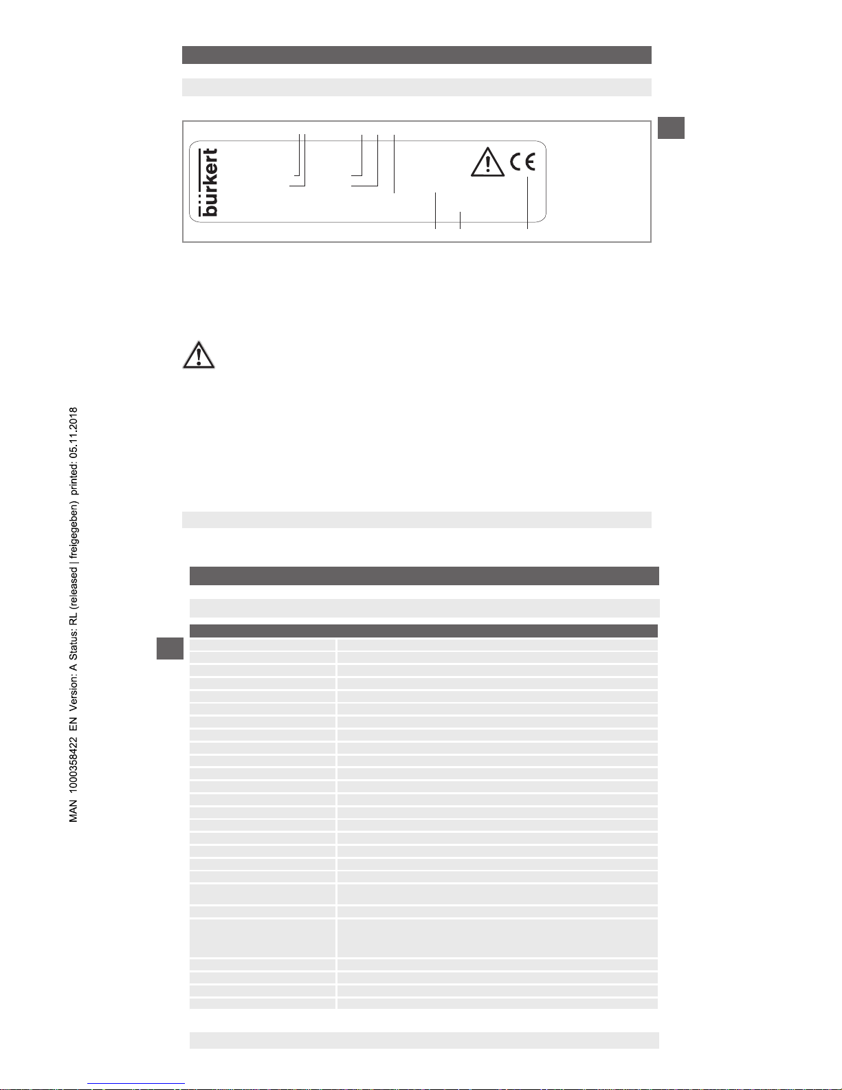
3. Labelling / safety marks
Product label (example)
FLUID CONTROL SYSTEMS
0 ... 16 bar
4 ... 20 mA
DC 10 ... 30 V DC max. 25 mA
Made in Germany
U+:1
U-:2
7M
8325
ID.-No. 569098
S# 11639110
www.burkert.com
P# product number
Power supply
S# serial number
Comply with the relevant European directives
Measuring range
Coded manufacturing date
Output signal
Pin assignment
If the serial number becomes illegible due to mechanical damage or overpainting, traceability will no longer be possible.
Before mounting and commissioning the instrument, ensure you read the Operating Instructions!
3. Labelling / safety marks
10
Bürkert Operating Instructions - Pressure transmitter Type 8325
EN
4. Specications of the transmitter 8325-S, ≥ 0,4 bar
Specications
Measuring range See product label or test report
Vacuum tightness Ye s
Reference conditions Per IEC 61298-1
■
Atmospheric pressure 15 ... 25 °C (59 ... 77 °F)
■
Atmospheric pressure 860 ... 1,060 mbar (12.5 ... 15.4 psi)
■
Humidity 45 ... 75 % r. h.
■
Power supply 24 V DC, 5 V DC with ratiometric output
■
Mounting position Calibrated in vertical mounting position with pressure connection facing downwards.
Settling time ≤ 3 ms
Output signal See product label or test report
Permissible load in Ω
■
Current output ≤ (power supply - 7.5 V) / 0.023 A
■
With optional settling time of 1 ms ≤ (power supply - 11.5 V) / 0.023 A
■
Voltage output > maximum output voltage / 1 mA
■
Ratiometric output > 4.5k
Switch-on time 150 ms
Switch-on drift 5 s (60 s with optional zero point adjustment 0.1 %)
Voltage supply See product label or test report
Dissipation loss
■
Current output 828 mW (22 mW/K derating of the dissipation loss with ambient temperatures ≥ 100 °C
(212 °F))
■
Voltage output 432 mW
Current supply External circuits connected to the electrical outputs of the transmitter must be energy-limited
electrical circuits in accordance with section 9.4 of UL/EN/IEC 61010-1, or an LPS to UL/EN/
IEC 60950-1, or class 2 in accordance with UL1310/UL1585 (NEC or CEC). External circuits
must be suitable for operation above 2,000 m should the transmitter be used at this altitude.
■
Current output Current signal, max. 25 mA
■
Voltage output Max. 12 mA
Non-linearity (per IEC 61298-2) See test report
Relationship to the mounting position For measuring ranges < 1 bar (15 psi), an additional zero oset of up to 0.15 % applies
4. Specications of the transmitter 8325-S, ≥ 0,4 bar
11
Bürkert Operating Instructions - Pressure transmitter Type 8325
EN
Specications
Non-repeatability ≤ ±0.1 % of span
Temperature hysteresis 0.1 % of span at > 80 °C (176 °F)
Long-term drift (per IEC 61298-2) ≤ ±0.1 % of span
≤ ±0.2 % of span (with special measuring ranges and measuring ranges < 1 bar (15 psi))
Temperature error For calibration temperature 15 ... 25 °C (59 ... 77 °F)
–20 ... +80 °C: ≤1 % of span
–30 ... +100 °C: ≤1.5 % of span
For measuring ranges < 1 bar (15 psi), special measuring ranges and instruments with an
increased overpressure limit the respective temperature error increases by 0.5 % of span
Derating for cooling elements
■
Max. permissible ambient temperature
T
amb
(T
med
< 125 °C) = 125 °C
T
amb
(T
med
≥ 125 °C) = –0.62 x T
med
+ 202 °C
■
Max. permissible medium temperature
T
med
(T
amb
< 80 °C) = 200 °C
T
med
(T
amb
≥ 80 °C) = –1.61 x T
amb
+ 326 °C
T
amb
= Ambient temperature [°C]
T
med
= Medium temperature [°C]
Storage and transport conditions
■
Permissible temperature range –40 ... +70 °C (–40 ... +158 °F)
■
Maximum humidity (per IEC 68-2-78) 67 % r. h. at 40 °C (104 °F) (in accordance with 4K4H per EN 60721-3-4)
Climate class For indoor and outdoor use. Protect the instrument from direct sunlight.
■
Storage 1K3 (per EN 60721-3-1)
■
Transport 2K3 (per EN 60721-3-2)
■
Operation 4K4H (per EN 60721-3-4, without condensation or icing)
Vibration resistance (per IEC 68-2-6) 20 g, 10 ... 2,000 Hz (40 g, 10 ... 2,000 Hz for circular connector M12 x 1, metallic)
For instruments with cooling elements a limited vibration resistance of 10 g, 10 ... 2,000 Hz,
applies.
Continuous vibration resistance (per
IEC 68-2-6)
10 g
Shock resistance (per IEC 68-2-27) 100 g, 6 ms (500 g, 1 ms for heavy-duty connector)
Service life 100 million load cycles (10 million load cycles for measuring ranges > 600 bar/7,500 psi)
Free-fall test (following IEC 60721-3-2)
■
Individual packaging 1.5 m (5 ft)
■
Multiple packaging 0.5 m (1.6 ft)
■
PE bag 0.5 m (1.6 ft)
4. Specications of the transmitter 8325-S, ≥ 0,4 bar
12
Bürkert Operating Instructions - Pressure transmitter Type 8325
EN
Specications
Electrical protective measures The electrical protective measures are not valid for ratiometric output signals.
■
Short-circuit resistance S+ vs. U–
■
Reverse polarity protection U+ vs. U–
■
Resistance to overvoltage 40 V DC
■
Insulation voltage 750 V DC
Materials of wetted parts
■
Relative measuring ranges Measuring ranges ≤ 10 bar (150 psi): 316L
Measuring ranges > 10 bar (150 psi): 316L + 13-8 PH
■
Absolute measuring ranges Measuring ranges ≤ 1,000 bar (10,000 psi): ASTM 630 and 13-8 PH
Measuring ranges > 1,000 bar (10,000 psi): 316L + 13-8 PH
Materials of non-wetted parts
■
Case 316 Ti
■
Zero point adjustment ring PBT/PET GF30
■
Angular connector DIN 175301-803 A PBT/PET GF30
■
Angular connector DIN 175301-803 C PBT/PET GF30
■
Circular connector M12 x 1 (4-pin) PBT/PET GF30
■
Circular connector M12 x 1 (4-pin,
metallic)
316L
■
Field case 316L, 316Ti
■
Heavy-duty connector 316L
■
Cable outlet IP 67 PA66, PBT/PET GF30
■
Cable outlet ½ NPT conduit 316L
■
Cable outlet IP 68 316L
■
Cable outlet IP 68, FEP 316L
■
Cable outlet IP 6K9K 316L
CE conformity
■
Pressure equipment directive
■
EMC directive, EN 61326 emission (group 1, class B) and interference immunity (industrial application)
■
EM eld 30 V/m (80 ... 1,000 Mhz)
4. Specications of the transmitter 8325-S, ≥ 0,4 bar
13
Bürkert Operating Instructions - Pressure transmitter Type 8325
EN
Specications
Approvals See product label
Dimensions Spanner width: 24 mm
Diameter: 26.7 mm
Length: 53 ... 105 mm, with cooling element additional 73 mm
Weight Approx. 150 g (0.331 lbs), with cooling element approx. 350 g (0.794 lbs)
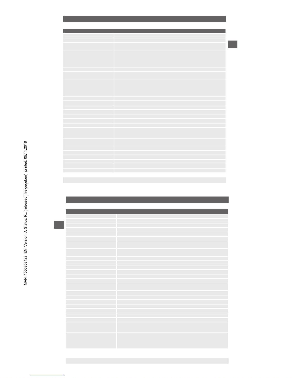
Electrical connections
Electrical connection Ingress
protection
2)
Wire cross-
section
Cable ∅ Cable
material
Permissible temperature
Angular connector DIN EN 175301-803 A
with mating connector IP65 max. 1.5 mm² 6 ... 8 mm - –30 ... +100 °C
(–22 ... +212 °F)
with mating connector (conduit) IP65 max. 1.5 mm² - - –30 ... +100 °C
(–22 ... +212 °F)
with mating connector with
moulded cable
IP65 3 x 0.75 mm² 6 mm PUR –30 ... +100 °C
(–22 ... +212 °F
with mating connector with
moulded cable, shielded
IP65 6 x 0.5 mm² 6.8 mm PUR –25 ... +85 °C
(–4 ... +185 °F)
Angular connector DIN EN 175301-803 C
with mating connector IP65 max. 0.75 mm² 4.5 ... 6 mm - –30 ... +100 °C (–22 ... +212 °F)
with mating connector with
moulded cable
IP65 4 x 0.5 mm² 6.2 mm PUR –25 ... +85 °C
(–4 ... +185 °F)
Circular connector M12 x 1 (4-pin)
without mating connector IP67 - - - –30 ... +100 °C
(–22 ... +212 °F)
4. Specications of the transmitter 8325-S, ≥ 0,4 bar
14
Bürkert Operating Instructions - Pressure transmitter Type 8325
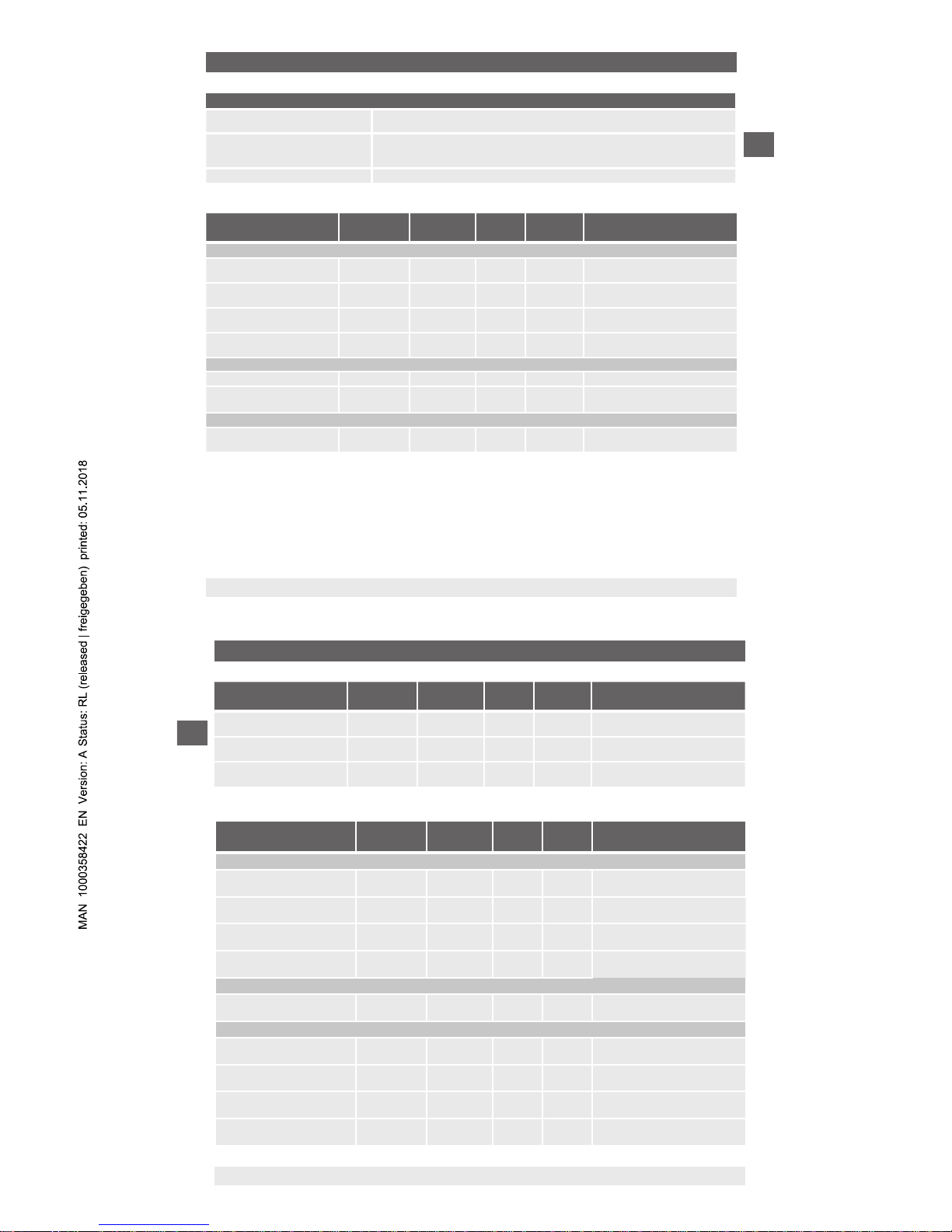
EN
Electrical connection Ingress
protection
2)
Wire cross-
section
Cable ∅ Cable
material
Permissible temperature
with mating connector, straight,
with moulded cable
IP67 3 x 0.34 mm² 4.3 mm PUR –25 ... +80 °C
(–4 ... +176 °F)
with mating connector, straight,
with moulded cable, shielded
IP67 3 x 0.34 mm² 4.3 mm PUR –25 ... +80 °C
(–4 ... +176 °F)
with mating connector, angled,
with moulded cable
IP67 3 x 0.34 mm² 5.5 mm PUR –25 ... +80 °C
(–4 ... +176 °F)
2) Only applies when plugged in using a suitable mating connector that has the appropriate ingress protection
Electrical connection Ingress
protection
2)
Wire cross-
section
Cable ∅ Cable
material
Permissible temperature
Circular connector M12 x 1 (4-pin, metallic)
without mating connector IP67 - - - –40 ... +125 °C
(–40 ... +257 °F)
with mating connector, straight, with
moulded cable
IP67 3 x 0.34 mm² 4.3 mm PUR
–25 ... +80 °C
(–4 ... +176 °F)
with mating connector, straight, with
moulded cable, shielded
IP67 3 x 0.34 mm² 4.3 mm PUR
–25 ... +80 °C
(–4 ... +176 °F)
with mating connector, angled, with
moulded cable
IP67 3 x 0.34 mm² 5.5 mm PUR
–25 ... +80 °C
(–4 ... +176 °F)
Field case
IP6K9K - - - –25 ... +100 °C
(–4 ... +212 °F)
Cable outlet
Cable outlet IP 67 IP67 3 x 0.34 mm² 5.5 mm PUR –30 ... +100 °C
(–22 ... +212 °F)
Cable outlet ½ NPT conduit IP67 6 x 0.35 mm² 6.1 mm PUR –30 ... +100 °C
(–22 ... +212 °F)
Cable outlet IP 68 IP68 6 x 0.35 mm² 6.1 mm PUR –30 ... +125 °C
(–22 ... +257 °F)
Cable outlet IP 68, FEP IP68 6 x 0.39 mm² 5.8 mm FEP –40 ... +125 °C
(–40 ... +257 °F)
4. Specications of the transmitter 8325-S, ≥ 0,4 bar
 Loading...