

Page 1
Instruction Manual
8223
INDUCTIVE CONDUCTIVITY SENSOR
© Bürkert 2001 Subject to technical change without notice
Page 2

2
8223
ENGLISH
INTRODUCTION
Table des matières
INTRODUCTION ............................................................................................................... 2
1.1 Symbol used ..............................................................................................................3
1.2 General safety instructions .................................................................................... 3
QUICK START ................................................................................................................... 4
2.1 Quick installation guide ........................................................................................... 4
CONFIGURATION ............................................................................................................ 6
3.1 General comments ................................................................................................... 6
3.2 Measuring range ....................................................................................................... 6
3.2.1 Measuring range of the conductivity ............................................................................6
3.2.2 Measuring range of the temperature ...........................................................................8
3.3 Filtering level .............................................................................................................. 9
3.4 Temperature compensation .................................................................................10
3.4.1 Specific compensation ......................................................................................................... 10
3.4.2 Linear compensation ............................................................................................................. 11
3.5 Transmission of the temperature .........................................................................12
3.6 Calibrating the “zero conductivity” point ...........................................................12
INSTALLATION ............................................................................................................... 13
4.1 Mounting instructions ............................................................................................13
4.1.1 Temperature-pressure diagram..................................................................................... 13
4.1.2 Installation recommendations .........................................................................................13
4.2 Mounting...................................................................................................................14
4.3 Electrical connection instructions .......................................................................15
4.3.1 Mounting and connection of the EN 175301-803 connector ...........15
4.3.2 Connecting the 8223 to an external device (PLC,...) ..................................16
4.3.3 Precautions during installation and commissioning .....................................16
4.4 Examples of connections with a 8223 sensor .........................................................17
MAINTENANCE .............................................................................................................. 18
5.1 Maintenance ............................................................................................................18
5.2 If a problem occurs... .............................................................................................18
TECHNICAL DATA .........................................................................................................20
6.1 Process characteristics.........................................................................................20
6.2 Electrical characteristics .......................................................................................20
6.3 User characteristics ...............................................................................................21
6.4 Safety ........................................................................................................................21
6.5 Environment .............................................................................................................21
6.6 Conformity with standards ...................................................................................21
6.7 Dimensions (mm) ....................................................................................................22
INFORMATION ...............................................................................................................23
7.1 Standard delivery ....................................................................................................23
7.2 Ordering table for sensors 8223 ........................................................................23
7.3 Ordering table for spare parts .............................................................................23
7.4 Measurement principle ..........................................................................................24
7.5 Label description ....................................................................................................24
7.6 Declaration of conformity ......................................................................................26
Page 3

3
8223
ENGLISH
INTRODUCTION
1.1 SYMBOL USED
Indicates information which must be followed. Failure to follow the in for ma tion could endanger the user and affect the function of the device.
1.2 GENERAL SAFETY INSTRUCTIONS
Before installing or using this product, please read this manual and any
other rel e vant documentation to ensure you fully benefit from all the
ad van tag es the prod uct can offer.
- Please verify that the product is complete and free from any damage.
- It is the customer's responsibility to select an appropriate sensor for the
application, ensure the unit is installed correctly, and main tain all com po nents.
- This product should only be installed or repaired by specialist staff using the
correct tools.
- Please observe the relevant safety regulations throughout the operation,
maintenance and repair of the product.
- Always ensure that the power supply is switched off and the pipes / tank do
not contain any pressure before working on the device / system.
- This electronic device is sensitive to electrostatic discharge. To avoid any
damage by immediate electrostatic discharge, pay attention to the
requirements of EN 100 015-1.
- Always protect the device from electromagnetic perturbations, ultraviolet radiations
and, when installed outside, from the effects of climatic conditions.
- If these instructions are ignored or the device is not used according to the
specifications, no liability will be accepted and the guarantee on the device and
accessories will become invalid.
Page 4
4
8223
ENGLISH
QUICK START
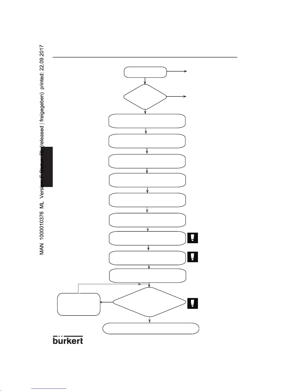
2.1 QUICK INSTALLATION GUIDE
Order code
OK ?
Verify that the delivered
product is complete.
See § 7.1
Yes
No
Unscrew the 2 plugs
Select the measuring range
using SW1
Use a coin for instance
Select the filtering level using SW1
Select the temperature com pen sa tion
using SW2 *
Select the type of current output
using SW3
Open the EN 175301-803 connector
Connect the power supply cable to
the EN 175301-803 connector
Re-mount the EN 175301-803 con-
nector and connect it to the sensor
Green
LED flashes once briefly
every 2 s and current output
indicates 4 mA?
Yes
No
Press the push-
button for 2 s
Contact your
Bürkert agent
Install the appliance on the pipe
See the con fi gu ra tion
table opposite and
para graph 3.2.
See the con fi gu ra tion
table opposite and
paragraph 3.3
See the con fi gu ra tion
table opposite and
paragraph 3.4
Ensure that the
cable is not
pow ered.
See § 4.1
Power the sensor
* or the trans mis sion
of the temperature on
the 4-20 mA output.
See § 3.4
See the con fi gu ra tion
table opposite and
paragraph 4.3.2
Drive home
the connector
screw.
See § 4.3.1
The sensor
must be out of
the fluid.
See § 3.6
Unpack the
ap pli ance
Page 5
5
8223
ENGLISH
QUICK START
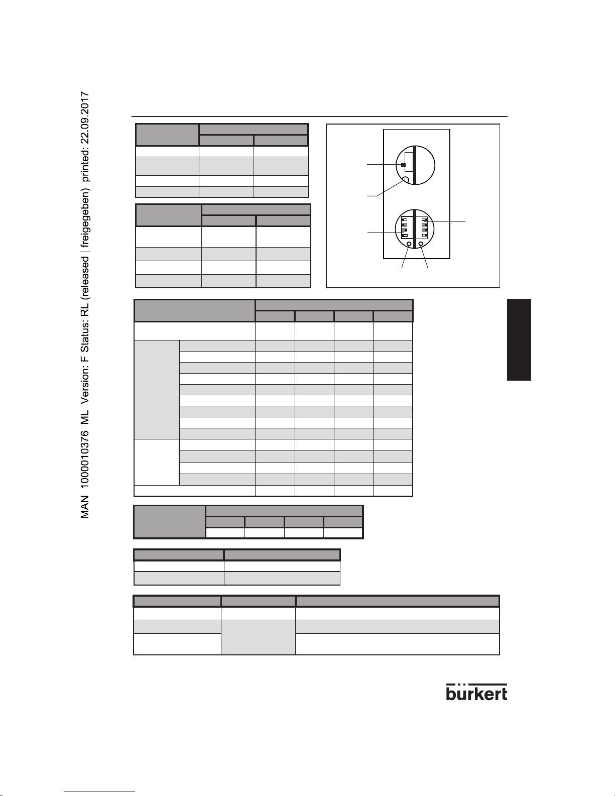
1
2
3
4
4
3
2
1
Push-
button
SW3
sink ing
sourc ing
SW1
OFF<->ON
Green LED Red LED
SW2
ON<->OFF
<->
See also § 5.2 for any other LED flashing.
Measuring range
Position of the switches of SW1
12
0 to 1 mS/cm OFF OFF
0 to 10 mS/cm
(default value)
OFF ON
0 to 100 mS/cm ON OFF
0 to 1 S/cm ON ON
Filtering level
Position of the switches of SW1
34
0 (no filtering)
(default value)
OFF OFF
1 (min. filtering) OFF ON
2 (medium filtering) ON OFF
3 (max. filtering) ON ON
Temperature compensation
Position of the switches of SW2
1234
No compensation
(default value)
OFF OFF OFF OFF
Linear compensation
0.1% ON OFF OFF OFF
0.25% OFF ON OFF OFF
0.5% ON ON OFF OFF
0.7% OFF OFF ON OFF
1% ON OFF ON OFF
1.5% OFF ON ON OFF
2% ON ON ON OFF
3% OFF OFF OFF ON
5% ON OFF OFF ON
Specific
compensation
NaOH OFF ON OFF ON
HNO
3
ON ON OFF ON
H
2SO4
OFF OFF ON ON
NaCl ON OFF ON ON
Not used OFF ON ON ON
Transmission of the
temperature to the
4-20 mA output
Position of the switches of SW2
1234
ON ON ON ON
Type of current output Position of switch SW3
Sinking (default value)
Up
Sourcing Down
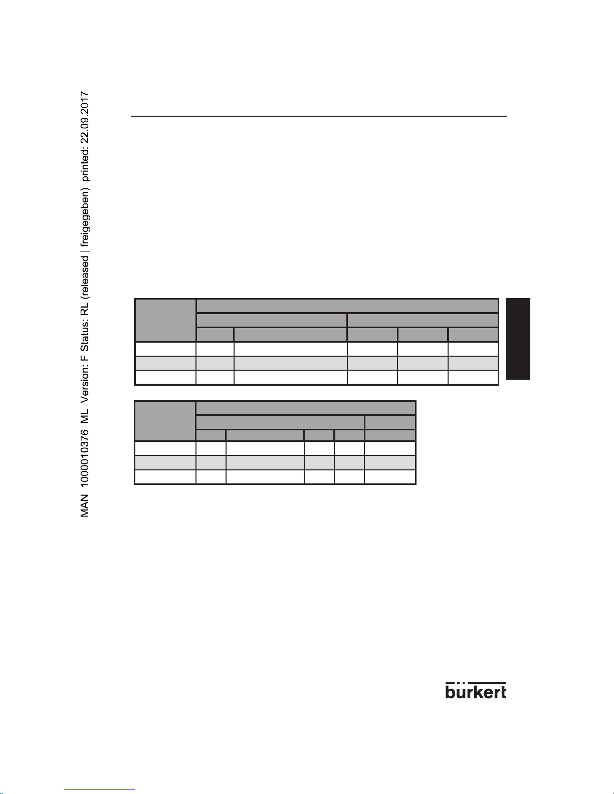
Green LED Red LED Status of the sensor when operating faultless
ON ON Calibration of the "zero conductivity" in progress
Flashes once briefly
OFF
Measurement of a nil conductivity (< 2% of the full scale)
Flashes at a fequency
between 0,5 and 16 Hz
Measurement of a conductivity which is proportional to this frequency
Page 6
6
8223
ENGLISH
CONFIGURATION
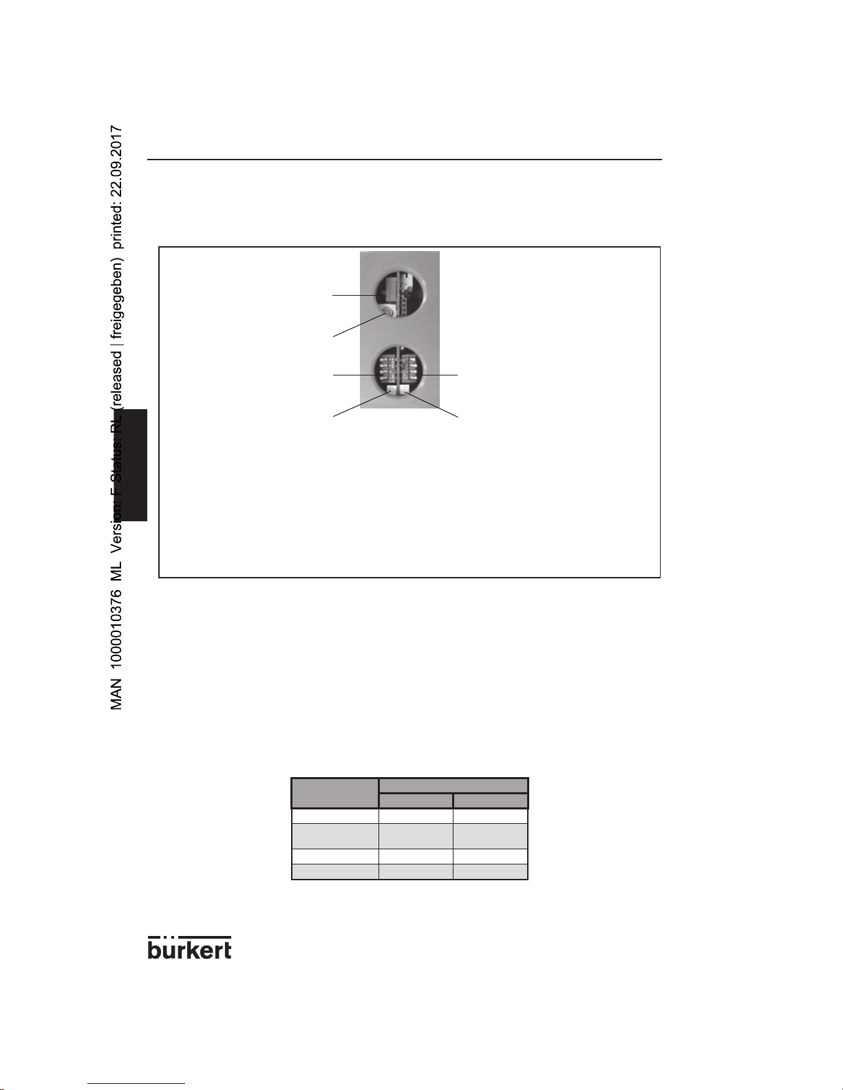
3.1 GENERAL COMMENTS
Configuration is done by means of accessible switches after having unscrewed the plugs
counterclockwise and removed them.
- SW1 allows the selection of:
- the measuring range (switches 1 and 2)
- the filtering level of the conductivity (switches 3 and 4)
- SW2 allows the selection of the temperature compensation or the
transmission of the temperature on the 4-20 mA output.
- SW3 allows the selection of the current output mode, sinking or sourcing.
- The push-button allows the calibration of the sensor «zero conductivity» point.
3.2 MEASURING RANGE
The 4-20 mA output delivers a current which is proportional to the compensated or not
compensated conductivity or to the measured temperature. For the con duc tiv i ty, the user
may choose the mea sur ing range.
When the conductivity exceeds the full scale by 10%, the current output delivers a 22 mA
current. As soon as the conductivity is again equal or inferior to the full scale value, the current
output delivers a current between 4 and 20 mA.
3.2.1 Measuring range of the conductivity
SW1 makes it possible to select the conductivity mea sur ing range:
- a 4 mA current indicates a conductivity which is equal to 0 mSiemens/cm
(less than 2% of the selected full scale)
Push-button
SW1 SW2
Green LED Red LED
SW3
Measuring range
Position of the switches of SW1
12
0 to 1 mS/cm OFF OFF
0 to 10 mS/cm
(default value)
OFF ON
0 to 100 mS/cm ON OFF
0 to 1 S/cm ON ON
Page 7
7
8223
ENGLISH
CONFIGURATION
- a 20 mA current indicates a conductivity which is equal to either:
- 1 mSiemens/cm (mS/cm)
- 10 mS/cm
- 100 mS/cm
- 1 S/cm
The conductivity depending on the material the used fitting is made of and its diameter, the full scale value must be re-calculated using the following for mu la:
FS = FS
s
x C
F
where FS = Full Scale value to be programmed on the PLC
FSs = selected Full Scale
CF = Correction factor of the fitting used: see the following tables
- If a fitting with DN15, 20 or 25 is used, use the correction factor of the DN32
- If a fitting with a DN > 100 or a vessel is used, apply a correction factor = 1.
Example:
The 8223 sensor is installed in a PVDF S020 fitting with DN32.
The selected full scale is FS
s
= 10 mS/cm.
The correction factor for this fitting is C
F
= 1,113.
Thus: FS = FS
s
x CF = 10 x 1,113 = 11,13 mS/cm
DN of the
fitting
Correction factor
Weld-ends / Internal and external threads True-union / Solvent and fusion spigots
Brass Stainless steel PVDF PP PVC
DN32 0.991 0.989 1.113 1.098 1.093
DN40 0.989 0.989 1.049 1.045 1.045
DN50 0.985 0.983 1.022 1.021 1.022
DN of the
fitting
Correction factor
Weld-ends Saddles
Brass Stainless steel PVDF PP PVC
DN65 - 0.993 1.020 1.019 1.025
DN80 - 0.995 1.020 1.019 1.022
DN100 - 0.998 1.019 1.017 1.010
Page 8
8
8223
ENGLISH
CONFIGURATION
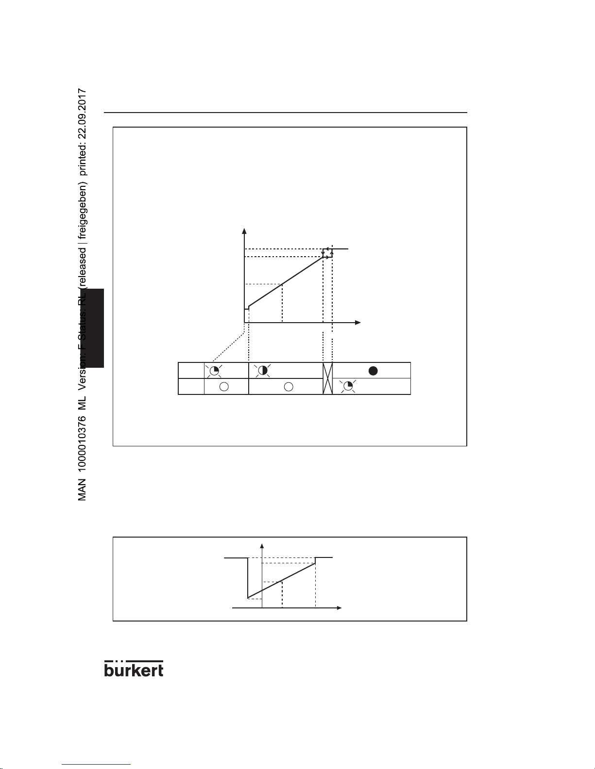
Example:
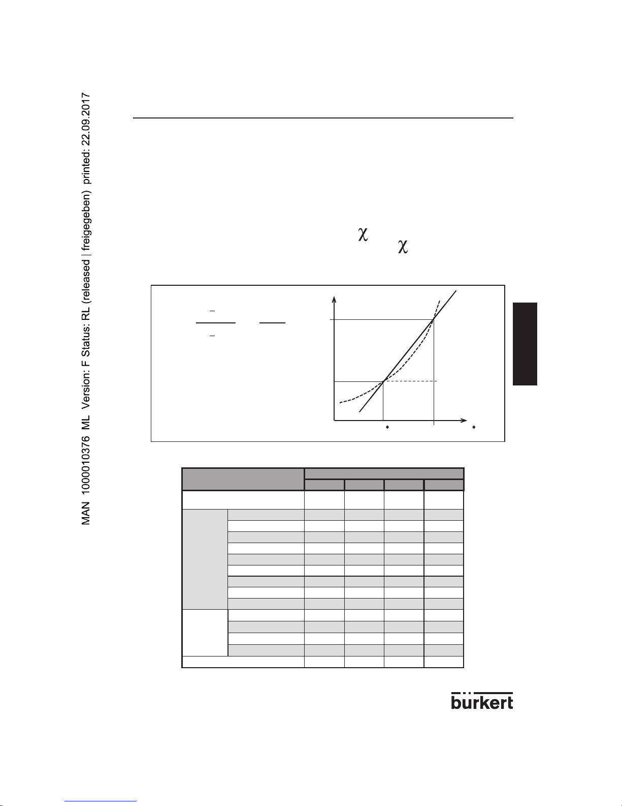
If the selected measuring range is: „0 to 10 mS/cm”.
When the fluid conductivity measured by the sensor is < 2% of the full scale,
the 4-20 mA output delivers a 4 mA current; When the conductivity measured by the
sensor is equal to 10 mS/cm, the 4-20 mA output delivers a 20 mA current.
The curve hereunder shows the ratio between the measured conductivity and the
current value delivered by the 4-20 mA output.
When the conductivity exceeds the full scale by 10% (11 mS/cm in the example), the current output delivers a 22 mA current. As soon as the conductivity is again equal or inferior
to the full scale value, the current output delivers a current between 4 and 20 mA.
3.2.2 Measuring range of the temperature
- The value of the temperature which corresponds to a 4-mA current is always -10 °C
- The value of the temperature which corresponds to a 20-mA current is always 80 °C
If the 8223 has been programmed to transmit the temperature (and not the con duc tiv i ty) on the 4-20 mA output (all SW2 switches are set to ON), the cor re spond ing
temperature/4-20 mA-output curve is the following:
The current output delivers a 22 mA current if the temperature is < -10 °C or > 80 °C.
4
20
mA
0
10
mS/cm
5
12
0,2
22
11
Green
LED
Red
LED
0,5 - 16 Hz
every 2 s
every
2 s
4
20
mA
080
°C
35
12
22
-10
Page 9
9
8223
ENGLISH
CONFIGURATION
mS/cm
mS/cm
mS/cm
mS/cm
t (s)
t (s)
t (s)
t (s
)
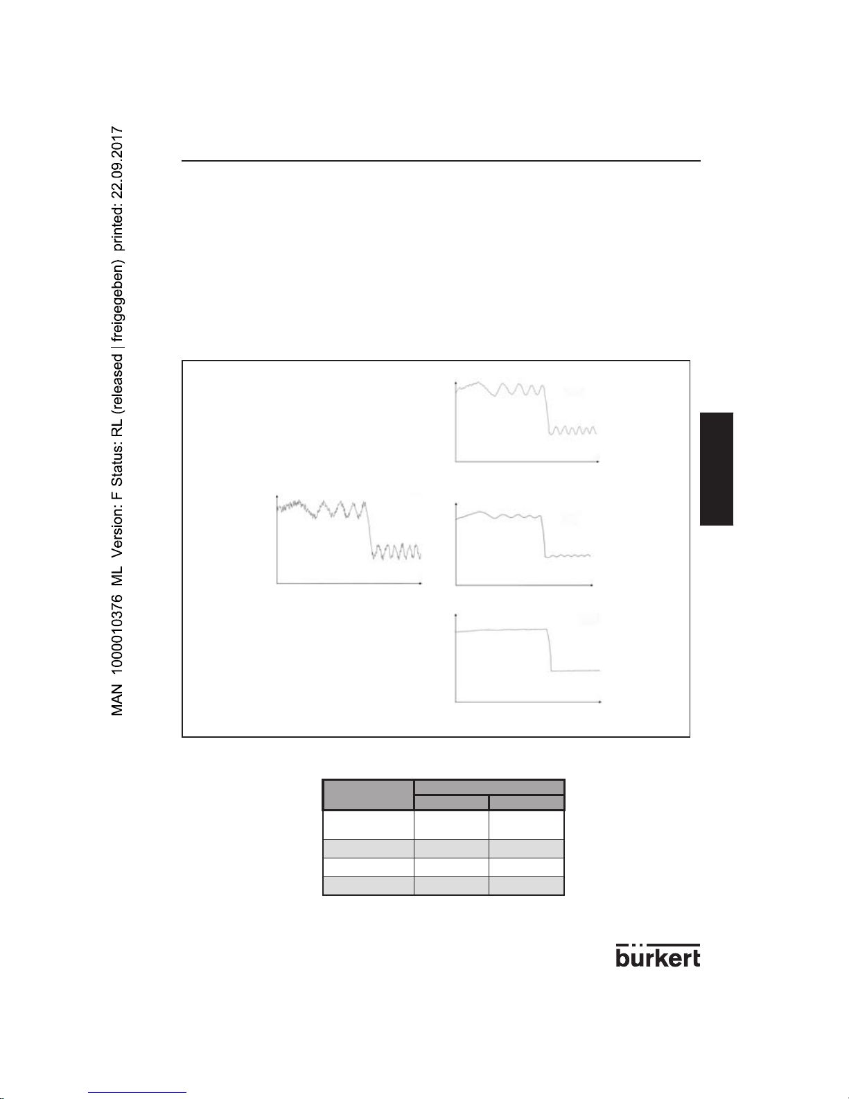
3.3 FILTERING LEVEL
Filtering allows the attenuation of fluctuations in the conductivity. The 8223 sensor has
four filtering levels, from 0 to 3:
- Level 0 corresponds to a nil filtering: the sensor indicates any conductivity variation
- Level 3 corresponds to the maximum filtering: the sensor smoothes the
conductivity variations at the most
- Levels 1 and 2 correspond to intermediate filterings.
SW1 allows the selection of the filtering level:
Level 0 fil ter ing
Level 1 fil ter ing
Level 2 fil ter ing
Level 3 fil ter ing
Filtering level
Position of the switches of SW1
34
0 (no filtering)
(default value)
OFF OFF
1 (min. filtering) OFF ON
2 (medium filtering) ON OFF
3 (max. filtering) ON ON
Page 10
10
8223
ENGLISH
CONFIGURATION
3.4 TEMPERATURE COMPENSATION
The conductivity varies with the temperature; To compensate the variations, the 8223
sensor measures the real conductivity and temperature of the fluid then re-calculates the
conductivity corresponding to a temperature of 25 °C.
SW2 makes it possible to choose the calculation mode of the temperature com pen sa tion.
Three calculation modes are possible, either:
- a specific compensation: 4 compensation curves are memorized by the
sensor for the following solutions: NaOH (sodium hydroxyde), HNO
3
(nitric
acid), H2SO4 (sulphuric acid), and NaCl (sodium chloride).
- a linear compensation: 9 compensation factors, from 0.1 to 5% can be chosen.
- no compensation.
3.4.1 Specific compensation
The specific compensation curves for NaOH (sodium hydroxyde), HNO
3
(nitric acid) and
NaCl (sodium chloride) are valid for temperatures ranging from 10 to 70 °C.
The specific compensation curve for H
2SO4
(sulphuric acid) is valid for tem per a tures
ranging from 5 to 55 °C.
The compensation has been determined at the following concentrations:
NaOH : 1%
HNO
3
: 1%
NaCl : 0,2%
H
2SO4
: 20%
- The NaCl specific curve is valid for concentrations ranging from 60 mg/l
(conductivity ≅ 100 µS/cm) to 270 g/l (conductivity ≅ 220 mS/cm).
- The NaCl compensation curve can be used for some dilute solutions.
- If the fluid of your process does not correspond to any specific solution, use one
of the linear compensations.
Page 11
11
8223
ENGLISH
CONFIGURATION
3.4.2 Linear compensation
If no specific compensation curve corresponds to your process, use one of the 9 linear
compensation factors by using SW2.
If you do not know the compensation factor (average
α) of your process, you can deter-
mine it by doing the following:
1) Measure the conductivity of the fluid at 25 °C ( )
2) Measure the conductivity of the fluid at a temperature T ( )
3) Apply the following formula to determine the
α factor:
4) Use the compensation factor nearest to the calculated one:
25
°
T
α =
χ
χ
T
x
1
25°
χ
25°
25° T
χ
χ
25
25 C
T C
Τ
χ
T
Temperature compensation
Position of the switches of SW2
1234
No compensation
(default value)
OFF OFF OFF OFF
Linear compensation
0.1% ON OFF OFF OFF
0.25% OFF ON OFF OFF
0.5% ON ON OFF OFF
0.7% OFF OFF ON OFF
1% ON OFF ON OFF
1.5% OFF ON ON OFF
2% ON ON ON OFF
3% OFF OFF OFF ON
5% ON OFF OFF ON
Specific
compensation
NaOH OFF ON OFF ON
HNO
3
ON ON OFF ON
H
2SO4
OFF OFF ON ON
NaCl ON OFF ON ON
Not used OFF ON ON ON
Page 12

12
8223
ENGLISH
CONFIGURATION
3.5 TRANSMISSION OF THE TEMPERATURE
If, instead of the conductivity, the 8223 sensor is meant to transmit the tem per a ture
(be tween -10 °C and 80 °C) to the 4-20 mA output, configure SW2 as follows:
Thus the conductivity measuring range chosen with SW1 is not taken into account.
3.6 CALIBRATING THE “ZERO CONDUCTIVITY” POINT
The “zero conductivity” point of the sensor can drift in time. To check whether the sensor is
correctly calibrated or not, measure the conductivity of the air (conductivity = 0).
- Dismantle the sensor from the pipe.
Ensure the finger orifice the fluid passes through is clean and dry.
- If the conductivity of the air > 0 (the current output indicates a value > 4 mA and
the green LED flashes at a frequency between 0.5 and 16 Hz), press the push
button for at least 2 s: both LEDs light up and the sensor starts calibrating its
zero conductivity” point.
The operation can last a few minutes.
The calibration is finished when the two LEDs are not steadily lit any more. Then:
- If the red LED switches off and the green LED flashes rapidly every 2 s, the sensor
is correctly calibrated.
- If the green LED lights up and the red LED flashes 3 or 4 times every 2 s, the
calibration has failed: press the push-button briefly to go back to normal operating
using the parameters of the previous calibration.
- If the calibration fails several times in a row, contact your Bürkert agent.
Push-button
Green LED Red LED
Transmission of the
temperature to the
4-20 mA output
Position of the switches of SW2
1234
ON ON ON ON
Page 13
13
8223
ENGLISH
INSTALLATION
4.1 MOUNTING INSTRUCTIONS
4.1.1 Temperature-pressure diagram
The sensor and the fitting in which it is installed have limited operating temperatures and
pressures. The diagram hereunder shows the operating range of the 8223-fitting assembly, for each fitting material:
A: Operating range of the assembly 8223+fitting
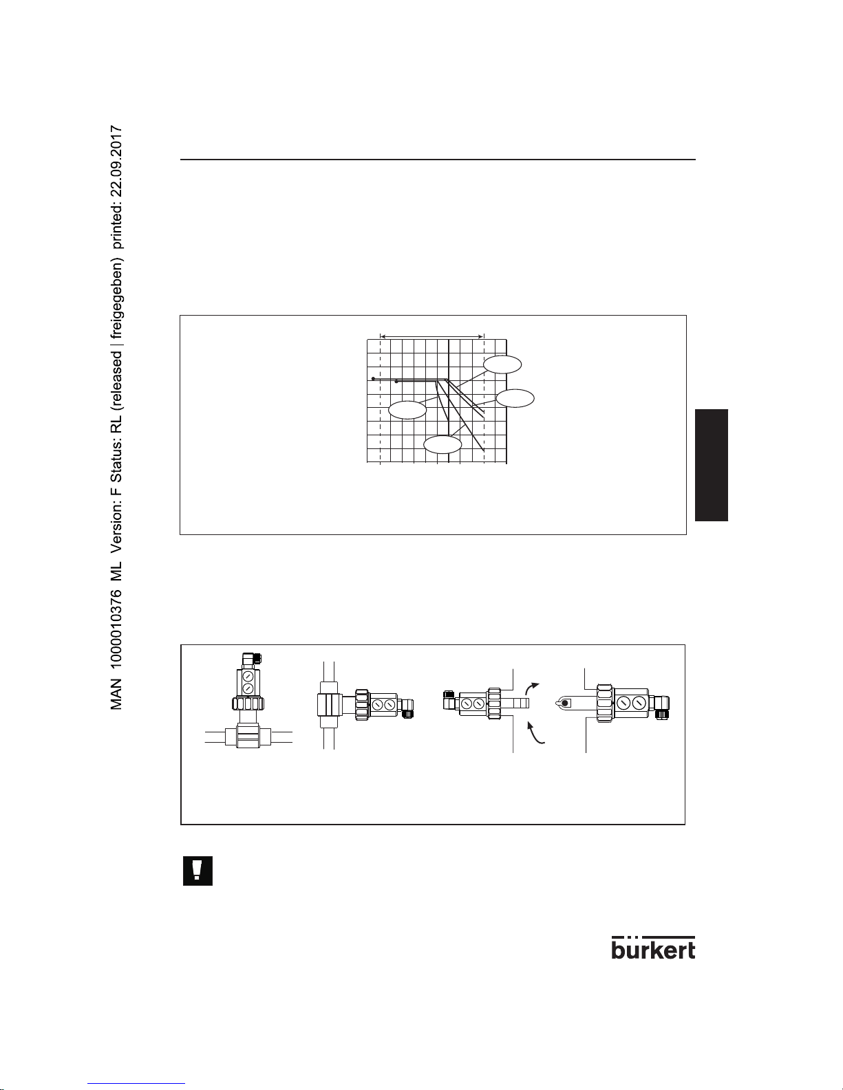
4.1.2 Installation recommendations
Choose a mounting position which avoids the building of air bubbles or cavities within the
finger orifice.
Position 1: horizontal or vertical mounting onto a pipe.
Position 2: mounting on a vessel without stirring
Position 3: mounting on a vessel with stirring
- When dismounting the sensor from the pipe, take all the precautions
related to this process.
- Ensure the fluid passage orifice is in the direction of the flow.
1
2
3
-10
+20 +40 +60
+80
+100
0
2
1
3
4
5
6
7
8
P [bar]
0
T [°C]
A
PVC
PP
PVDF
Metal
Page 14
14
8223
ENGLISH
INSTALLATION
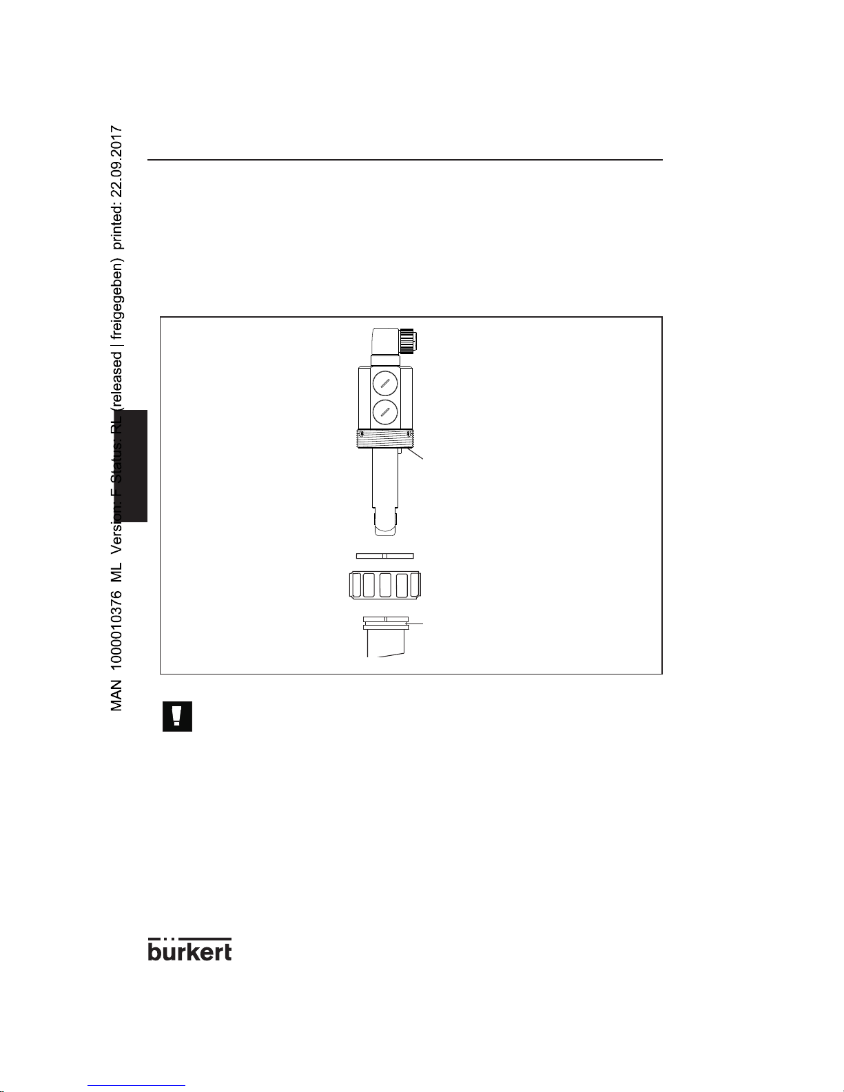
4.2 MOUNTING
The 8223 conductivity sensor is installed on a pipe as follows:
- Insert the nut [4] on the fitting [6] and clip the ring [3] in the groove [5].
- Insert the sensor [1] into the fitting [6] by ensuring the gasket [2] is in its right place.
- Screw on the nut and tighten by hand only.
- Ensure the gasket material (FKM in standard) is chemically compatible
with your process.
- One EPDM gasket and one FKM gasket are additionally supplied with
the sensor.
- Make sure the gasket is not damaged when replacing it.
1
3
4
5
6
2
Page 15
15
8223
ENGLISH
INSTALLATION
1
3
2
4.3 ELECTRICAL CONNECTION INSTRUCTIONS
Always ensure that the appliance is not powered before working on it. All the connections must be
disconnected.
- Use a shielded cable with a limit operating temperature > +80°C.
- Under normal con di tions of use, a shielded cable of 0.75 mm
2
section is sufficient
for signal transmission.
- Do not install the line close to high voltage or high frequency cables.
- If adjacent laying is unavoidable, keep a minimum distance of 30 cm.
- Connect the shielding to earth.
- Use a quality power supply (filtered and regulated).
- Do not open or cable the sensor when powered.
- It is essential that a 100 mA fuse be used for the power supply.
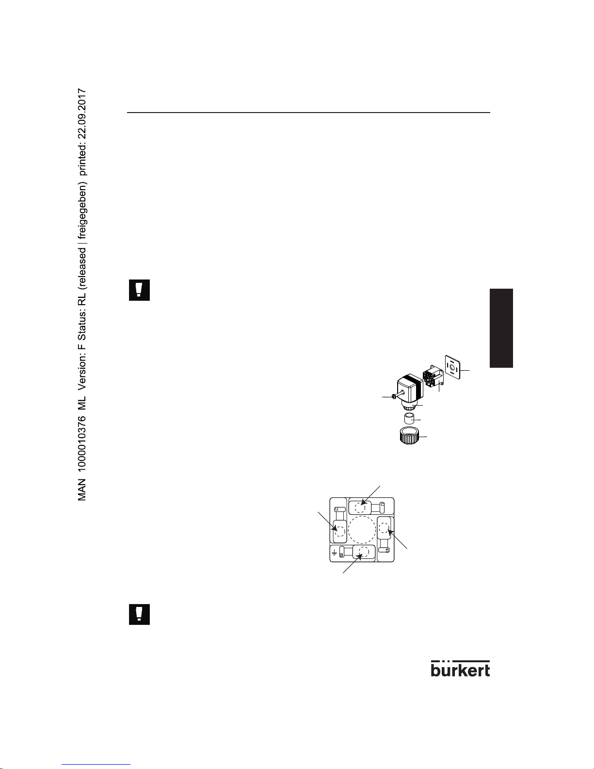
4.3.1 Mounting and connection of the EN 175301-803 connector
- Remove part [3] from part [2].
- Unscrew the cable gland [5].
- Insert cable into part [2] via cable gland.
- Wire part [3] (see below)
- Replace part [3].
- Tighten the cable gland [5].
- Place gasket [4] between the connector and the
fixed connector of the 8223.
- Connect the connector to the 8223.
- Tighten screw [1] to ensure tightness and correct electrical contact
Always check the connection of the connectors to ensure correct operation of the appliance.
L+
(12-30 VDC)
4-20 mA output
L-
Not connected
1
3
4
5
6
2
Page 16
16
8223
ENGLISH
INSTALLATION
4-20 mA
+
-
12-30 VDC
+
-
100 mA
I
1
3
2
SW3
4-20 mA
+
-
12-30 VDC
+
-
100 mA
I
1
3
2
SW3
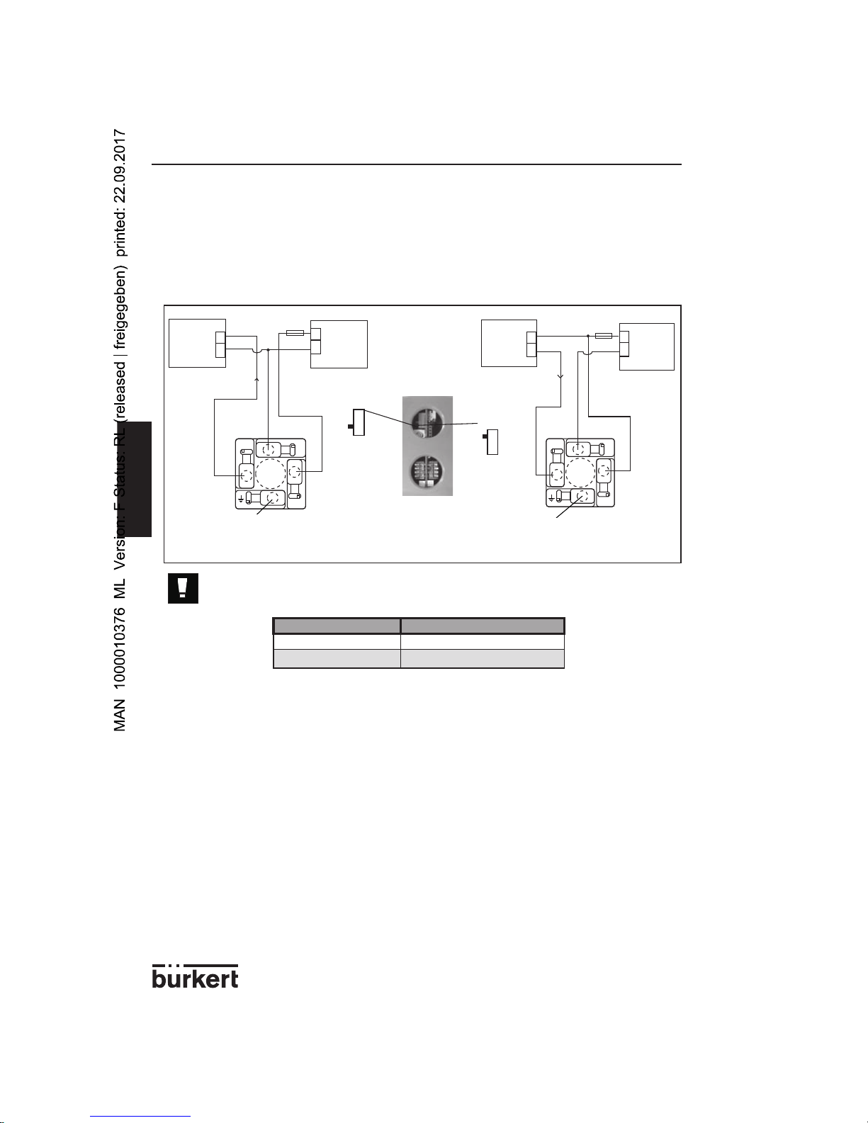
4.3.2 Connecting the 8223 to an external device (PLC,...)
The 8223 sensor can be connected to a PLC or any other device which is able to use the
4-20 mA signal transmitted by the sensor.
The connection can be carried out either in sourcing or in sinking mode, as shown by the
figures below:
SW3 must be configured correctly when the sensor is not powered, de pend ing on the connection mode chosen.
4.3.3 Precautions during in stal la tion and com mis sion ing
- When the appliance is powered and the cover is open, the protection against electrical
shocks is no longer effective.
- Always verify the chemical compatibility of the materials which are in contact with the
fluid to be measured.
- When cleaning the appliance use products which are chemically compatible with the
materials in the appliance.
- Do not insert any object (screwdriver for instance) within the finger orifice. When the
orifice is dirty, use compressed air to clean it.
PLC
PLC
Connection in sourcing mode Connection in sinking mode
Type of current output Position of switch SW3
Sinking (default value)
Up
Sourcing Down
not connected
not connected
Page 17
17
8223
ENGLISH
INSTALLATION
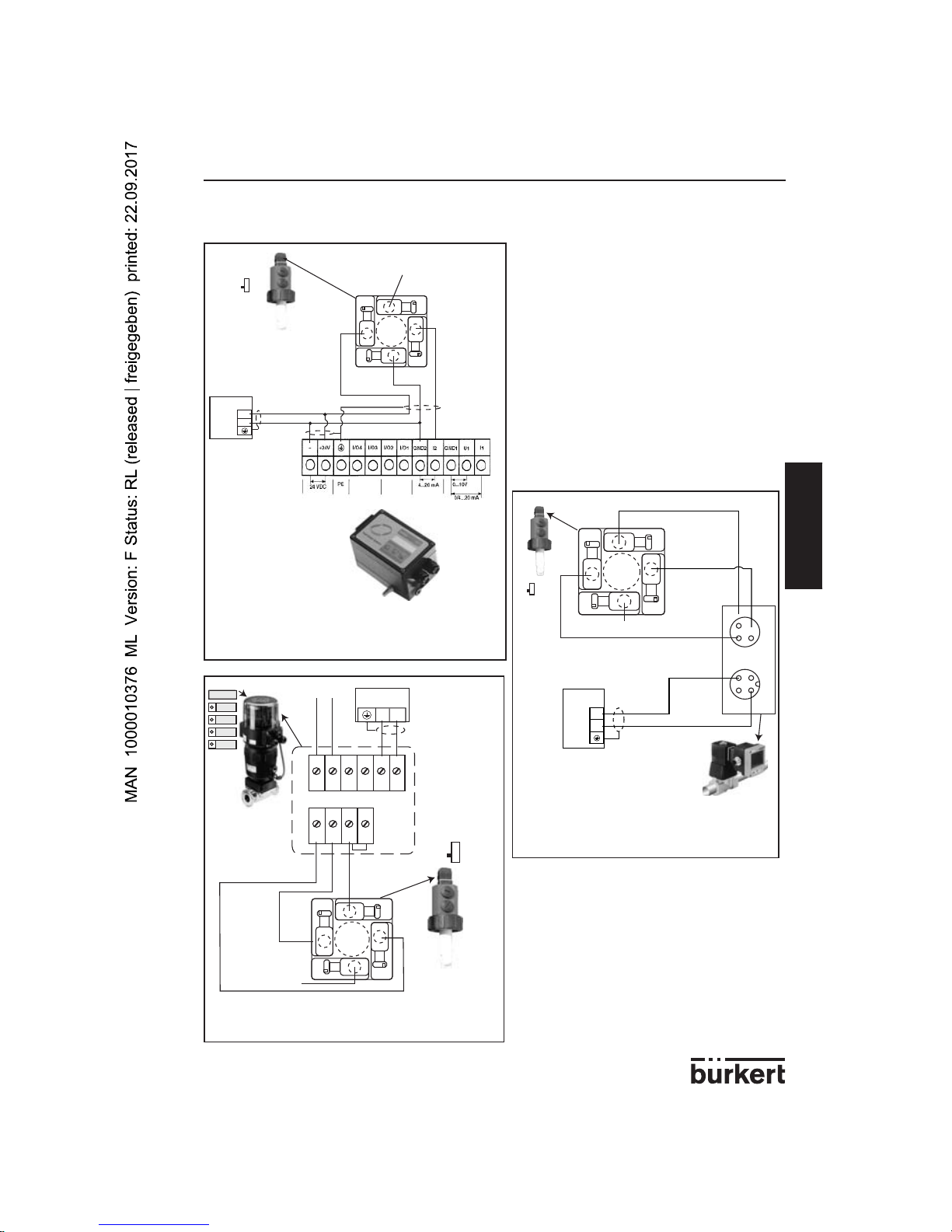
4.4 EXAMPLES OF CONNECTIONS WITH A 8223 SENSOR
Between the 8223 sensor and the 1067
positioner.
Between the 8223 sensor and a solenoid valve with 8624-2 PI controller.
Between the 8223 sensor and the 8630 Top
Control mounted on a 2031 diaphragm valve
8223
+
-
24 V=
1
3
2
L+
L-
I
SW3
1067
4-20 mA
8223
+
-
24 V=
1
3
2
L+
L-
SW3
4
3
1
2
4
3
1
Setpoint +
Setpoint -
24 V=
+
-
9
10
7
8
65
3
4
1
2
+-+
-
+
-
I
+24 V
SW3
1
3
2
2031+ 8630
8223
4-20 mA
L-
L+
not connected
not connected
not connected
Page 18
18
8223
ENGLISH
MAINTENANCE
5.1 MAINTENANCE
The 8223 sensor may be cleaned with water or a product which is compatible with the
materials therein.
Your Bürkert supplier is available to provide you with any additional information you
require.
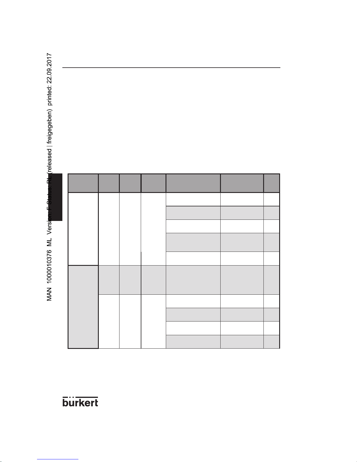
5.2 IF A PROBLEM OCCURS...
An error is indicated by lighting up of the green LED, special flashing of the red LED and
the transmission of a 22-mA current to the current output.
The following table lists possible faults that can occur and their solutions:
Problem
Green
LED
status
Red
LED
status
Current
output
status
Possible cause Do the following
See
also
The sensor
does not
work
OFF OFF 0 mA
The sensor is not connected
Connect the sensor 4.3
The fuse of the installation
is in a bad condition
Change the fuse -
The switch of the installation is set to OFF
Set the switch to
ON
-
The power supply has
been wrong connected to
the + and - terminals
Check the wiring 4.3
The power supply is not
stable or < 12 VDC
Change the power
supply
-
The sensor
measures a
wrong conductivity
flashes
briefly
OFF 4 mA
The "zero conductivity"
point has been calibrated
within the fluid or the "zero
conductivity" point has
drifted
carry out a calibration in air
3.5
flashes OFF -
The finger is dirty
Clean the sensor
finger
5.1
Air bubbles appear within
the finger orifice
Follow the mountign
instructions
4.1.2
The temperature compensation is not correct
Select an appropriate compensation
3.4
The conductivity fluctuations are very important
Select a higher filtering level (SW1)
3.3
Page 19

19
8223
ENGLISH
MAINTENANCE
Problem
Green
LED
status
Red LED
status
Current
output
status
Possible cause Do the following
See
also
The sensor
transmits a
nil conductivity
flashes
briefly
OFF 4 mA
The chosen measuring
range is not appropriate
Select the lower
measuring range
(SW1)
3.2
The sensor
transmits
no current
at all
flashes flashes 0 mA
SW3 is not set correctly
(sinking or sourcing)
Modify SW3 4.3.2
The current output is not
connected properly
Re-connect the
current output
4.3
The sensor
is stopped
- an error is
indicated
ON
flashes
once
briefly
every 2 s
22 mA
The conductivity > full scale
+ 10%
Select the next
measuring range
(SW1)
3.2.1
ON
flashes
twice
briefly
every 2 s
22 mA
The fluid temperature
< -10 °C or > +80 °C
Bring the fluid
temperature back
to a value within the
sensor measuring
range
3.2.2
ON
flashes
3 or 4
times
briefly
every 2 s
22 mA
The "zero conductivity" point
calibration failed
Press the pushbutton briefly.
If the error persists,
send the device
back to Burkert.
3.6
flash simultaneously 22 mA The sensor is out of service
Send the device
back to Burkert
-
Page 20

20
8223
ENGLISH
TECHNICAL DATA
6.1 PROCESS CHARACTERISTICS
Conductivity measurement
- Type of measurement Inductive conductivity measurement
- Measuring range 0 µS/cm to 1 S/cm
- Precision +/-2% of the selected measuring range
(within the range 0-70 °C)
- Temperature deviation 0.2% / °C max.
- Answering time at a strong
conductivity change < 1 s
- Sampling frequency measurement every 250 ms
Temperature measurement
- Type of measurement digital measurement
- Measuring range -10 °C to 80 °C
- Precision +/- 0.5 °C
- Answering time at a strong
conductivity change 100 s
- Sampling frequency 250 ms
Process data
- Pipe interface standard Bürkert fitting
- Pressure class PN6
- Fluid temperature range -10 °C to 80 °C
- Materials in contact with the fluid Finger: PVDF, PEEK or PP
Seals: FKM or EPDM
6.2 ELECTRICAL CHARACTERISTICS
Pulse rate output
- Output type current output from 4 to 20 mA (error signal at 22 mA)
- Electrical wiring Wiring in sourcing or sinking mode, can be
selected by bipolar reverser
- Max. load resistance 1000 Ohms with a power supply of 30 V
690 Ohms with a power supply of 24 V
300 Ohms with a power supply of 15 V
150 Ohms with a power supply of 12 V
- Adjustment 4 conductivity ranges and 1 temperature range,
can be selected by switch
Electrical connection
- Power supply voltage 12 to 30 VDC, filtered and regulated
- Maximum current consumption 50 mA max. + 22 mA for the current output
- Connector type EN 175301-803
Page 21

21
8223
ENGLISH
TECHNICAL DATA
6.3 USER CHARACTERISTICS
- Measurement indication By a green-coloured led flashing from 0.5
to 16 Hz depending on the conductivity;
It flashes briefly every 2 seconds when the
fluid conductivity is lower than 2% of the
selected full scale
- Error message By two green and red-coloured
leds (see 5.2)
- Programming the scale of measurement 4 measurement ranges selectable by
means of 2 switches
- Filtering the conductivity 4 filtering levels selectable by means of
2 switches
- Temperature compensation 14 compensation types
(9 pro por tion al com pen sa tion levels
and 4 solution specific levels),
selectable by means of 4 switches
(reference tem per a ture = 25 °C)
- Calibration of «zero conductivity» point By means of a push-button
6.4 SAFETY
Electrical input and output protected against polarity reversal.
6.5 ENVIRONMENT
- Operating and storage temperatures 0 to 60 °C
- Operating and storage humidity rating < 80%, non condensated
- Housing material PEHD
- Protection rating IP65, connector plugged in and
tightened
6.6 CONFORMITY WITH STANDARDS
Electromagnetic compatibility:
- Emission EN 50081-1 (1992)
- Protection EN 50082-2 (1995)
- Safety EN 61010-1
Page 22
22
8223
ENGLISH
TECHNICAL DATA
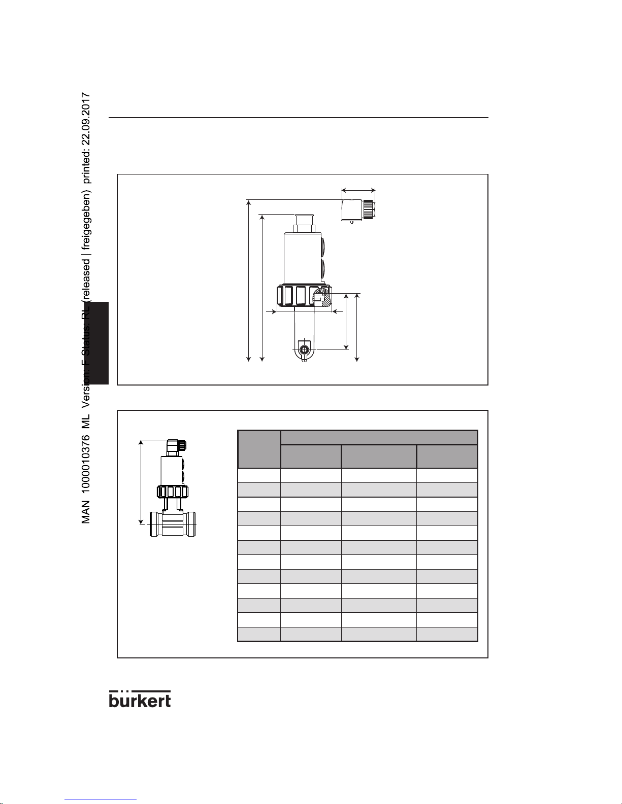
6.7 DIMENSIONS (MM)
218
46
75
200
78
95
H
DN (mm)
H (mm)
T fitting Plastic spigot
Stainless steel
spigot
15 204.3
20 201.8
25 202.0
32 205.6
40 209.4 205.3
50 215.5 210.3
65 215.5 220.3 214.3
80 225.3 221.3
100 232.3 231.3
125 242.3
150 253.3
200 274.3
Page 23
23
8223
ENGLISH
INFORMATION
7.1 STANDARD DELIVERY
The standard delivery comprises:
- an 8223 sensor
- a set with 1 EPDM gasket + 1 FKM gasket
- an EN 175301-803 connector
7.2 ORDERING TABLE FOR SENSORS 8223
7.3 ORDERING TABLE FOR SPARE PARTS
Spare part Order code
EN 175301-803 socket with cable gland (type 2508) + screw + NBR gasket
438811
EN 175301-803 socket with cable gland (type 2508) + screw + silicone gasket
156927
EN 175301-803 socket with NPT 1/2'' reduction (type 2509) + screw + NBR gasket
162673
Silicone gasket for EN 175301-803 socket
440244
Set of 2 M20x1.5 plugs + 2 gaskets
444705
Retaining ring
619205
Tightening nut
619204
Set of gaskets (1 FKM, green + 1 EPDM, black)
552111
Output type Finger material Order code
4-20 mA
PVDF
440440
PP
558767
PEEK
550335
Page 24
24
8223
ENGLISH
INFORMATION
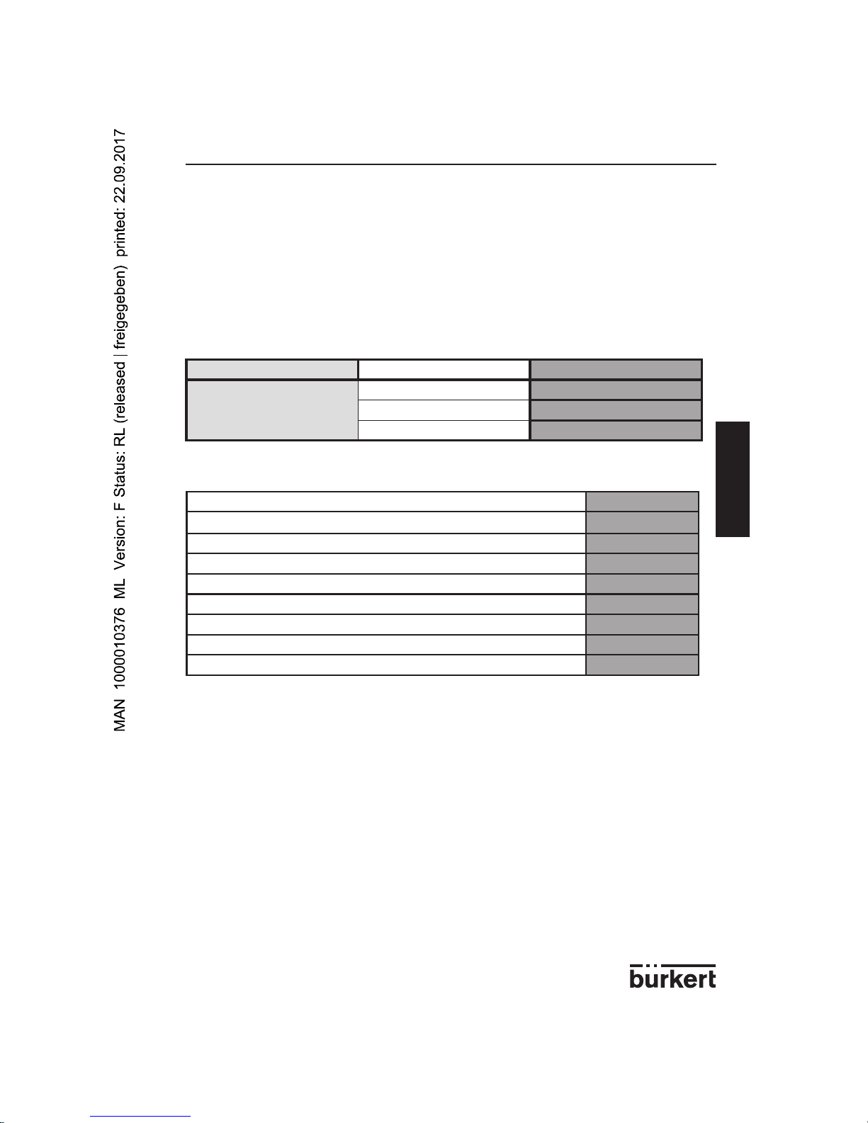
7.4 MEASUREMENT PRINCIPLE
Conductivity is the ability of a liquid / solution to conduct an electrical current. To measure
the conductivity of a solution the 8223 conductivity sensor uses the following principle:
- A voltage is connected to the primary magnetic coil.
- The induced magnetic field generates a current in the secondary magnetic coil.
- The intensity of the current is a direct function of the conductivity of the solution
between the 2 magnetic coils.
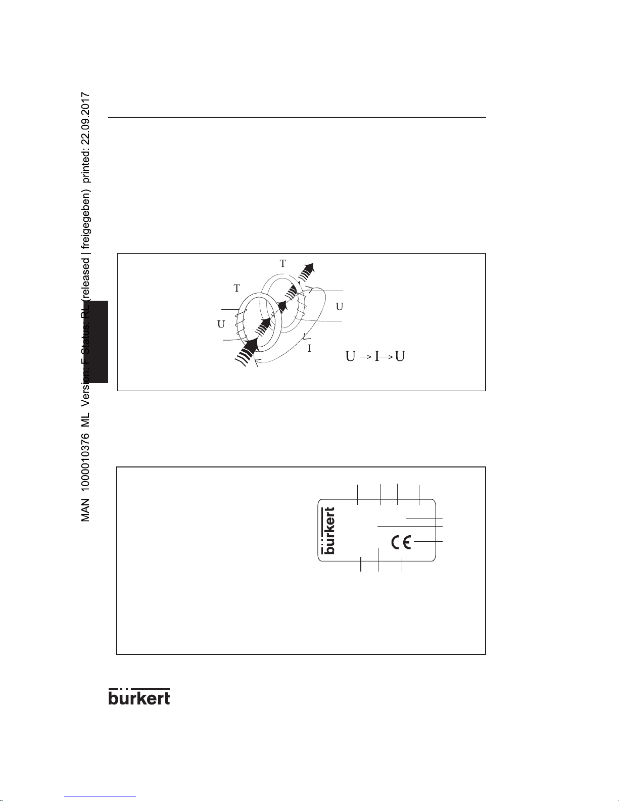
7.5 LABEL DESCRIPTION
1. Measured variable
2. Type of the sensor
3. Material of the gasket
4. Material of the finger
5. Power supply data
6. Type of output
7 CE logo
8. Manufacturing code
9. Series number
10. Order code
Made in France
COND:8223-FKM -PVDF
12-30V= 50 mA
4-20mA
N=10000
440440 W41UE
132
8910
4
5
6
7
Conducting fluid
1
1
1
2
2
2
Page 25

25
8223
ENGLISH
INFORMATION
Page 26

26
8223
ENGLISH
INFORMATION
7.6 DECLARATION OF CONFORMITY
Page 27

Manuel utilisateur
8223
CAPTEUR DE CONDUCTIVITÉ
PAR INDUCTION
© Bürkert 2001 Sous réserve de mo di fi ca tions techniques
Page 28

2
8223
FRANCAIS
INTRODUCTION
Table des matières
INTRODUCTION ............................................................................................................... 2
1.1 Symbole utilisé .......................................................................................................... 3
1.2 Consignes de sécurité ............................................................................................ 3
QUICK START ................................................................................................................... 4
2.1 Guide d’installation rapide .....................................................................................4
CONFIGURATION ............................................................................................................ 6
3.1 Généralités.................................................................................................................6
3.2 Etendue de mesure ..................................................................................................6
3.2.1 Etendue de mesure de la conductivité ........................................................................6
3.2.2 Etendue de mesure de la température ............................................................................8
3.3 Niveau de filtrage ...................................................................................................... 9
3.4 Compensation en température ...........................................................................10
3.4.1 Compensation spécifique ..................................................................................................10
3.4.2 Compensation linéaire ........................................................................................................ 11
3.5 Transmission de la température ..........................................................................12
3.6 Calibrage du point "zéro conductivité" du capteur .........................................12
INSTALLATION ............................................................................................................... 13
4.1 Consignes de montage.........................................................................................13
4.1.1 Diagramme température-pression .............................................................................13
4.1.2 Recommandations d’installation ...................................................................................13
4.2 Montage....................................................................................................................14
4.3 Consignes de raccordement électrique............................................................15
4.3.1 Montage et raccordement du connecteur EN 175301-803 ............... 15
4.3.2 Raccordement du 8223 à un appareil extérieur (API,...) .......................... 16
4.3.3 Précautions lors de l‘installation et la mise en service ............................... 16
4.4 Exemples de connexions réalisables avec le 8223 ........................................17
MAINTENANCE .............................................................................................................. 18
5.1 Entretien ...................................................................................................................18
5.2 En cas de problème ...............................................................................................18
CARACTERISTIQUES TECHNIQUES .......................................................................20
6.1 Spécifications relatives au procédé ...................................................................20
6.2 Spécifications électriques ....................................................................................20
6.3 Spécifications utilisateur .......................................................................................21
6.4 Sécurité ....................................................................................................................21
6.5 Environnement ........................................................................................................21
6.6 Conformité aux normes .........................................................................................21
6.7 Dimensions sans et avec un raccord s020 (mm) ...........................................22
INFORMATION ...............................................................................................................23
7.1 Contenu de la livraison ..........................................................................................23
7.2 Références de commande des capteurs complets .......................................23
7.3 References de commande des pieces detachees .........................................23
7.4 Principe de mesure ................................................................................................24
7.5 Description de l'étiquette ......................................................................................24
7.6 Déclaration de conformité ....................................................................................26
Page 29

3
8223
FRANCAIS
INTRODUCTION
1.1 SYMBOLE UTILISÉ
Consigne à suivre impérativement ; son non respect risque de mettre en
dan ger la sécurité de l‘utilisateur et de nuire au fonctionnement correct
de l‘ins tal la tion.
1.2 CONSIGNES DE SÉCURITÉ
Avant l‘installation ou l‘utilisation de cet instrument, veuillez lire at ten ti ve ment ce manuel et toute documentation s‘y rapportant afin de bénéficier de tou tes les pos si bi li tés qu‘il est susceptible de vous offrir.
- Vérifiez que la livraison est conforme et sans dommages.
- Il est de la responsabilité de l‘utilisateur de sélectionner le capteur approprié à
son application, de l‘installer correctement et d‘assurer sa maintenance.
- L‘utilisateur doit veiller à la compatibilité chimique des matériaux qui composent
le capteur.
- Cet appareil doit être installé et entretenu par du personnel habilité et avec des
outils adaptés.
- Respectez les consignes de sécurité lors des manipulations, de la maintenance
ou de la réparation de l‘appareil.
- Ne pas intervenir lorsque l‘appareil/système est sous tension.
- Cet appareil contient des composants électroniques sensibles aux décharges
électrostatiques ; Pour ne pas endommager l’appareil, prenez toutes les
précautions décrites dans la norme EN 100 015-1.
- Protéger l’appareil contre les perturbations électromagnétiques, les rayons
ultraviolets et, lorsqu’il est installé à l’extérieur, des effets des conditions
climatiques.
- Nous déclinons toute responsabilité en cas de non respect de ces instructions et
dénonçons toute clause de garantie.
Page 30

4
8223
FRANCAIS
QUICK START
2.1 GUIDE D’INSTALLATION RAPIDE
Déballer l‘appareil
Référence de
commande
OK ?
Vérifier que la livraison
est complète.
Voir § 7.1
Oui
Non
Dévisser les 2 obturateurs
Sélectionner l‘étendue de mesure
à l‘aide de SW1
Utiliser une pièce de
monnaie par ex.
Sélectionner le niveau de filtrage
à l‘aide de SW1
Sélectionner la compensation en
température à l‘aide de SW2 *
Sélectionner le type de sortie courant
à l‘aide de SW3
Ouvrir le connecteur
EN 175301-803
Connecter le câble d‘alimentation sur
le connecteur EN 175301-803
Remonter le connecteur EN 175301-
803 et l‘insérer sur le capteur
Le voyant
vert clignote-t-il briè ve ment 1 fois toutes
les 2 s et la sortie courant indique-t-elle
4 mA ?
Oui
Non
Appuyer sur le
bouton poussoir
pendant 2 s
Contacter votre
agent Bürkert
Installer l‘appareil sur la canalisation
Voir tableau de con fi gu ra tion ci-con tre
et § 3.2
Voir tableau de con fi gu ra tion ci-con tre
et § 3.3
Voir tableau de con fi gu ra tion ci-con tre
et § 3.4
Assurez-vous
que le câble est
hors ten sion.
Voir § 4.1
Mettre l’appareil sous tension
* ou la trans mis sion
de la tem pé ra tu re sur
la sortie 4-20 mA.
Voir § 3.4
Voir tableau de con fi gu ra tion ci-con tre
et § 4.3.2
Serrer à fond la
vis placée sur le
connecteur.
Voir § 4.3.1
Le capteur doit
être hors fluide.
Voir § 3.6
Page 31

5
8223
FRANCAIS
QUICK START
Boutonpoussoir
SW3
puits
sour ce
SW1
OFF<->ON
Voyant vert Voyant rouge
SW2
ON<->OFF
<->
Pour tous les autres clignotements, voir § 5.2.
1
2
3
4
4
3
2
1
Etendue de
mesure
Position des interrupteurs de SW1
12
0 à 1 mS/cm OFF OFF
0 à 10 mS/cm
(valeur par défaut)
OFF ON
0 à 100 mS/cm ON OFF
0 à 1 S/cm ON ON
Niveau de filtrage
Position des interrupteurs de SW1
34
0 (pas de filtrage)
(valeur par défaut)
OFF OFF
1 (filtrage min.) OFF ON
2 (filtrage moyen) ON OFF
3 (filtrage max.) ON ON
Compensation en température
Position des interrupteurs de SW2
1234
Pas de compensation
(valeur par défaut)
OFF OFF OFF OFF
Compensation linéaire
0.1% ON OFF OFF OFF
0.25% OFF ON OFF OFF
0.5% ON ON OFF OFF
0.7% OFF OFF ON OFF
1% ON OFF ON OFF
1.5% OFF ON ON OFF
2% ON ON ON OFF
3% OFF OFF OFF ON
5% ON OFF OFF ON
Compensation
spécifique
NaOH OFF ON OFF ON
HNO
3
ON ON OFF ON
H
2SO4
OFF OFF ON ON
NaCl ON OFF ON ON
Inutilisé OFF ON ON ON
Transmission de la
température sur la
sortie 4-20 mA
Position des interrupteurs de SW2
1234
ON ON ON ON
Type de sortie courant Position de l'interrupteur SW3
Puits (valeur par défaut)
Haute
Source Basse
Etat voyant vert Etat voyant rouge Etat du capteur en fonctionnement normal
Allumé Allumé Calibrage du point "zéro conductivité" en cours
Clignote 1 fois brièvement
Eteint
Mesure d'une conductivité nulle (< 2% de la pleine échelle de mesure)
Clignote à une fréquence
comprise entre 0,5 et 16 Hz
Mesure une conductivité proportionnelle à cette fréquence
Page 32

6
8223
FRANCAIS
CONFIGURATION
3.1 GÉNÉRALITÉS
La configuration est réalisée par l’intermédiaire des commutateurs ac ces si bles après
avoir dévissé, dans le sens inverse des aiguilles d’une montre, et retiré les obturateurs.
- SW1 permet de sélectionner :
- l‘étendue de mesure (interrupteurs 1 et 2)
- le niveau de filtrage de la conductivité (interrupteurs 3 et 4)
- SW2 permet de sélectionner la compensation en température ou de
transmettre la température sur la sortie 4-20 mA.
- SW3 permet de définir le mode de la sortie courant, puits ou source.
- Le bouton poussoir permet de calibrer le «zéro conductivité» du capteur.
3.2 ETENDUE DE MESURE
La sortie 4-20 mA délivre un courant proportionnel à la conductivité compensée ou non
compensée ou à la température mesurée. Pour la conductivité, l‘utilisateur peut choisir
l‘éten due de mesure.
Lorsque la conductivité dépasse la pleine échelle de 10%, la sortie courant délivre un
courant de 22 mA. Dès que la conductivité est à nouveau égale ou inférieure à la pleine
échelle, la sortie courant indique une valeur entre 4 et 20 mA.
3.2.1 Etendue de mesure de la conductivité
SW1 permet de sé lec tion ner l’éten due de mesure de la conductivité :
- Un courant de 4 mA indique une conductivité de 0 mSiemens/cm (inférieure
à 2% de la pleine échelle sélectionnée)
Bouton poussoir
SW3
SW1 SW2
Voyant vert
Voyant rouge
Etendue de
mesure
Position des interrupteurs de SW1
12
0 à 1 mS/cm OFF OFF
0 à 10 mS/cm
(valeur par défaut)
OFF ON
0 à 100 mS/cm ON OFF
0 à 1 S/cm ON ON
Page 33

7
8223
FRANCAIS
CONFIGURATION
- Un courant de 20 mA indique une conductivité égale à, soit :
- 1 mSiemens/cm (mS/cm)
- 10 mS/cm
- 100 mS/cm
- 1 S/cm
La conductivité étant fonction des matériau et diamètre du raccord utilisé, il faut
recalculer la valeur pleine échelle à l’aide de la formule suivante :
PE = PE
s
x C
F
PE = valeur pleine échelle à saisir sur l’automate
PEs = pleine échelle sélectionnée
CF = facteur de correction du raccord utilisé : voir tableaux ci-dessous
- Appliquer le facteur de correction du DN32 si vous utilisez un raccord de
DN15, 20 ou 25.
- Appliquer un facteur de cor rec tion = 1 si vous utilisez un raccord de DN > 100 ou un
ré ser voir.
Exemple :
- Capteur 8223 monté dans un raccord S020, DN32 en PVDF.
- La pleine échelle sélectionnée est PE
s
= 10 mS/cm.
- Facteur de correction pour ce raccord C
F
= 1,113.
Ainsi PE = PE
s
x CF = 10 x 1,113 = 11,13 mS/cm.
DN du raccord
Facteurs de correction
Embouts à souder / Taraudés / Filetés Raccord union / à coller / à souder
Laiton Acier inoxydable PVDF PP PVC
DN32 0.991 0.989 1.113 1.098 1.093
DN40 0.989 0.989 1.049 1.045 1.045
DN50 0.985 0.983 1.022 1.021 1.022
DN du raccord
Facteurs de correction
Embouts à souder Colliers de prise en charge
Laiton Acier inoxydable PVDF PP PVC
DN65 - 0.993 1.020 1.019 1.025
DN80 - 0.995 1.020 1.019 1.022
DN100 - 0.998 1.019 1.017 1.010
Page 34

8
8223
FRANCAIS
CONFIGURATION
Exemple :
Soit l‘étendue de mesure sélectionnée : „0 à 10 mS/cm“.
Lorsque la conductivité mesurée par le capteur est inférieure à 2% de la pleine
échelle, la sortie 4-20 mA délivre un courant égal à 4 mA ; Lorsque la conductivité
mesurée par le capteur est égale à 10 mS/cm, la sortie 4-20 mA délivre un courant
égal à 20 mA.
La courbe ci-dessous indique la relation entre la conductivité mesurée et la valeur du
courant délivrée par la sortie 4-20 mA :
La sortie courant fournit un courant de 22 mA lorsque la conductivité dépasse la pleine échelle de 10% (11 mS/cm dans l’exemple). La sortie courant indique à nou veau
un courant compris entre 4 et 20 mA dès que la conductivité est égale ou inférieure à
la pleine échelle.
3.2.2 Etendue de mesure de la température
- La valeur de la température correspondant à 4 mA est toujours égale à -10 °C.
- La valeur de la température correspondant à 20 mA est toujours égale à 80 °C.
Si le 8223 est programmé pour transmettre la température (et non la con duc ti vi té) sur la
sortie 4-20 mA (tous les interrupteurs de SW2 = ON), alors la courbe tem pé ra tu re-sortie
4-20 mA est la suivante :
La sortie courant fournit un courant de 22 mA lorsque la température < -10 °C ou > 80 °C.
4
20
mA
0
10
mS/cm
5
12
0,2
22
11
Voyant
vert
Voyant
rouge
0,5 - 16 Hz
toutes les 2 s
toutes
les 2 s
4
20
mA
080
°C
35
12
22
-10
Page 35

9
8223
FRANCAIS
CONFIGURATION
3.3 NIVEAU DE FILTRAGE
Le filtrage permet d’atténuer les fluctuations de conductivité. Le capteur 8223 com prend
4 niveaux de filtrage, notés de 0 à 3.
- Le niveau 0 correspond à un filtrage nul : le capteur indique la moindre
variation de conductivité.
- Le niveau 3 correspond à un filtrage maximal : le capteur lisse les fluctuations
de conductivité au maximum.
- Les niveaux 1 et 2 correspondent à des filtrages intermédiaires.
SW1 permet de sélectionner le niveau de filtrage :
mS/cm
mS/cm
mS/cm
mS/cm
t (s)
t (s)
t (s)
t (s
)
Filtrage Niveau 0
Filtrage Niveau 1
Filtrage Niveau 2
Filtrage Niveau 3
Niveau de filtrage
Position des interrupteurs de SW1
34
0 (pas de filtrage)
(valeur par défaut)
OFF OFF
1 (filtrage min.) OFF ON
2 (filtrage moyen) ON OFF
3 (filtrage max.) ON ON
Page 36

10
8223
FRANCAIS
CONFIGURATION
3.4 COMPENSATION EN TEMPÉRATURE
La conductivité varie en fonction de la température ; pour compenser cette va ria tion, le
capteur 8223 mesure la conductivité et la température réelles du fluide puis re-calcule la
conductivité équivalente à une température de 25 °C.
SW2 permet de sélectionner le mode de calcul de la compensation en température.
Trois modes sont possibles, soit :
- spécifique : 4 courbes de compensation sont mémorisées dans le capteur pour
les solutions suivantes : NaOH (hydroxyde de sodium), HNO
3
(acide
nitrique), H2SO4 (acide sulfurique) et NaCl (chlorure de sodium).
- linéaire : 9 facteurs de compensation, de 0,1 à 5 %, peuvent être sélectionnés.
- sans compensation.
3.4.1 Compensation spécifique
Les courbes spécifiques pour les solutions de NaOH (hydroxyde de sodium), HNO
3
(acide nitrique) et NaCl (chlorure de sodium) sont valables pour des tem pé ra tu res de 10
à 70 °C.
La courbe spécifique pour la solution de H
2SO4
(acide sulfurique) est valable pour des
températures de 5 à 55 °C.
La compensation a été déterminée pour les concentrations suivantes :
NaOH : 1%
HNO
3
: 1%
NaCl : 0,2%
H
2SO4
: 20%
- La courbe spécifique pour le NaCl est valable pour des concentrations de
60 mg/l (conductivité ≅ 100 µS/cm) à 270 g/l (conductivité ≅ 220 mS/cm).
- La courbe de compensation du NaCl peut être utilisée pour certaines solutions diluées.
- Si le fluide de votre application ne correspond à aucune solution spécifique, utiliser une
compensation linéaire.
Page 37

11
8223
FRANCAIS
CONFIGURATION
3.4.2 Compensation linéaire
Si aucune courbe de compensation spécifique ne correspond à votre ap pli ca tion, utilisez
l’un des 9 facteurs linéaires sélectionnables par SW2.
Si vous ne connaissez pas le facteur de compensation (α moyen) de votre ap pli ca tion,
déterminez-le en pro cé dant com me suit :
1) Mesurez la conductivité du fluide à 25 °C ( )
2) Mesurez la conductivité du fluide à la tem pé ra tu re
T de l’ap pli ca tion ( )
3) Appliquez la formule suivante pour déterminer le facteur
α :
4) Appliquez le facteur de compensation le plus proche du facteur calculé.
25°
T
α =
χ
χ
T
x
1
25°
χ
25°
25° T
χ
χ
25
25 C
T C
Τ
χ
T
Compensation en température
Position des interrupteurs de SW2
1234
Pas de compensation
(valeur par défaut)
OFF OFF OFF OFF
Compensation linéaire
0.1% ON OFF OFF OFF
0.25% OFF ON OFF OFF
0.5% ON ON OFF OFF
0.7% OFF OFF ON OFF
1% ON OFF ON OFF
1.5% OFF ON ON OFF
2% ON ON ON OFF
3% OFF OFF OFF ON
5% ON OFF OFF ON
Compensation
spécifique
NaOH OFF ON OFF ON
HNO
3
ON ON OFF ON
H
2SO4
OFF OFF ON ON
NaCl ON OFF ON ON
Inutilisé OFF ON ON ON
Page 38

12
8223
FRANCAIS
CONFIGURATION
3.5 TRANSMISSION DE LA TEMPÉRATURE
Si, au lieu de la conductivité, le 8223 doit transmettre la température mesurée (de -10 à
80 °C) sur la sortie 4-20 mA, programmer SW2 comme suit :
La sélection de l’étendue de mesure de la conductivité par SW1 n’est plus prise en
compte.
3.6 CALIBRAGE DU POINT "ZÉRO CONDUCTIVITÉ" DU CAPTEUR
Le point "zéro conductivité" du capteur peut dériver dans le temps. Pour vérifier que le
capteur est correctement calibré, il faut mesurer la conductivité de l’air (conductivité = 0).
- Démonter le capteur de la canalisation.
Vérifier que l’orifice de passage du fluide sur le doigt est propre et sec.
- Si la conductivité dans l’air est >0 (la sortie courant indique une valeur > 4 mA et le
voyant vert clignote à une fréquence de 0,5 à 16 Hz), appuyez sur le bouton-poussoir
pendant 2 secondes au moins : les 2 voyants s’allument et l’appareil effectue le
ca li bra ge du point "zéro conductivité".
Cette opération peut durer quelques minutes.
Le calibrage est terminé lorsque les 2 voyants ne sont plus allumés en continu.
Puis :
- Si le voyant rouge s’éteint et le voyant vert clignote rapidement toutes les 2 s, le
capteur est correctement calibré.
- Si le voyant vert s’allume et le voyant rouge clignote 3 ou 4 fois toutes les 2 s : le
calibrage a échoué : appuyer brièvement sur le bouton poussoir pour retourner au
mode de fonctionnement normal avec les paramètres du précédent calibrage.
- Si le calibrage échoue plusieurs fois de suite, contacter votre agence Bürkert.
Bouton poussoir
Voyant vert Voyant rouge
Transmission de la
température sur la
sortie 4-20 mA
Position des interrupteurs de SW2
1234
ON ON ON ON
Page 39

13
8223
FRANCAIS
INSTALLATION
4.1 CONSIGNES DE MONTAGE
4.1.1 Diagramme température-pression
Le capteur et le raccord dans lequel il est installé ont des températures et pressions de
fonctionnement limites. Le diagramme ci-dessous indique les plages de fonc tion ne ment de
l’ensemble 8223-raccord, pour les matériaux de raccord suivants : acier inoxydable, laiton,
PP, PVC et PVDF.
A : Plage de fonctionnement de l'ensemble 8223+raccord
4.1.2 Recommandations d’installation
Choisir une position de montage permettant d’éviter la formation de bulles ou de poches
d’air dans l’orifice du doigt.
Position 1 : montage horizontal ou vertical sur une conduite.
Position 2 : montage sur réservoir sans agitation
Position 3 : montage sur réservoir avec agitation
- Lors du démontage du capteur de la conduite, prenez toutes les
pré cau tions liées au procédé.
- Vérifier que l’orifice de passage du fluide est dans le sens de
circulation du fluide.
1
2
3
-10
+20 +40 +60
+80
+100
0
2
1
3
4
5
6
7
8
P [bar]
0
T [°C]
A
PVC
PP
PVDF
Métal
Page 40

14
8223
FRANCAIS
INSTALLATION
4.2 MONTAGE
Le capteur 8223 se monte sur une conduite de la façon suivante :
- Insérer l’écrou [4] sur le raccord [6] et clipser la bague [3] dans la rainure [5].
- Insérer le capteur [1] dans le raccord [6], en veillant au bon positionnement du joint [2].
- Visser l’écrou et serrer à la main uniquement.
- Vérifier la compatibilité du matériau du joint (FKM en standard) avec votre
process.
- Un joint en EPDM et un joint en FKM sont livrés en supplément avec le capteur.
- Veiller à ne pas détériorer le joint lors de son remplacement.
1
3
4
5
6
2
Page 41

15
8223
FRANCAIS
INSTALLATION
4.3 CONSIGNES DE RACCORDEMENT ÉLECTRIQUE
Assurez-vous toujours que l‘appareil est hors tension avant d‘effectuer toute intervention.
- Utilisez un câble blindé avec une température limite de service > +80° C (+176° F).
- Dans des conditions normales d’utilisation, du câble blindé de 0,75 mm
2
de section
suffit à la transmision du signal.
- Ne pas installer la ligne à proximité de câbles haute tension ou haute fréquence.
- Si une pose contiguë est inévitable, respecter une distance minimale de 30 cm.
- Relier correctement le blindage à la terre.
- Utilisez une alimentation de qualité (filtrée et régulée).
- Ne pas ouvrir ni câbler le capteur sous tension.
- Utiliser impérativement un fu si ble de 100 mA pour l‘alimentation.
4.3.1 Montage et raccordement du connecteur EN 175301-803
Vérifiez toujours le branchement des connecteurs pour assurer le bon
fonc tion ne ment de l‘appareil.
L+
(12-30 VDC)
Sortie 4-20 mA
L-
Non connecté
1
3
2
1
3
4
5
6
2
- Extraire la partie [3] de la partie [2] à l'aide d'un tournevis
plat.
- Dévisser le presse-étoupe [5].
- Insérer le câble dans la partie [2] via le presse-étoupe.
- Câbler la partie [3] (voir ci-dessous)
- Replacer la partie [3].
- Serrer le presse-étoupe [5].
- Placer le joint [4] entre le connecteur et son embase sur le
8223.
- Raccorder le connecteur au 8223.
- Serrer la vis [1] afin de garantir une étanchéité et un contact
électrique correct
Page 42

16
8223
FRANCAIS
INSTALLATION
4-20 mA
+
-
12-30 VDC
+
-
100 mA
I
1
3
2
SW3
4-20 mA
+
-
12-30 VDC
+
-
100 mA
I
1
3
2
SW3
4.3.2 Raccordement du 8223 à un appareil extérieur (API,...)
Le capteur 8223 peut être raccordé à un automate programmable (API) ou tout appareil
pouvant interpréter le signal de 4-20 mA qu’il délivre.
Le raccordement peut être effectué en mode source ou en mode puits con for mé ment aux
schémas ci-dessous :
Configurer correctement SW3, appareil hors tension, en fonction du
mode de fonc tion ne ment choi si.
4.3.3 Précautions lors de l‘installation et la mise en service
- Lorsque l‘appareil est sous tension et que les obturateurs sont retirés, la protection
contre les chocs électriques n‘est plus effective.
- Veillez toujours à la compatibilité chimique des matériaux en contact avec le fluide
à mesurer.
- Lors du nettoyage de l‘appareil, utilisez des produits chimiquement compatibles
avec les matériaux de l‘appareil.
- Ne pas introduire de corps étranger (tournevis, par ex.) dans l‘orifice du doigt. En
cas d‘encrassement, utiliser de l‘air comprimé.
Raccordement en mode source
Raccordement en mode puits
API API
Type de sortie courant Position de l'interrupteur SW3
Puits (valeur par défaut)
Haute
Source Basse
non connecté
non connecté
Page 43

17
8223
FRANCAIS
INSTALLATION
4.4 EXEMPLES DE CONNEXIONS RÉALISABLES AVEC LE 8223
Entre le capteur 8223 et le positionneur 1067
Entre le capteur 8223 et une électrovanne avec régulateur PI 8624-2.
Entre le capteur 8223 et le Top Control 8630
monté sur une vanne à mem bra ne 2031.
Setpoint +
Setpoint -
24 V=
+
-
9
10
7
8
65
3
4
1
2
+-+
-
+
-
I
+24 V
SW3
1
3
2
2031+ 8630
8223
4-20 mA
L-
L+
8223
+
-
24 V=
1
3
2
L+
L-
I
SW3
1067
4-20 mA
8223
+
-
24 V=
1
3
2
L+
L-
SW3
4
3
1
2
4
3
1
non connecté
non connecté
non connecté
Page 44

18
8223
FRANCAIS
MAINTENANCE
5.1 ENTRETIEN
Le capteur 8223 peut être nettoyé avec de l‘eau ou un produit compatible avec les ma té riaux qui le composent.
Votre fournisseur Bürkert reste à votre entière disposition pour tous ren sei gne ments
complémentaires.
5.2 EN CAS DE PROBLÈME
Une erreur est signalée par le voyant vert allumé et le clignotement particulier du voyant
rouge et par l’émission d’un courant de 22 mA sur sa sortie courant.
Le tableau ci-dessous liste les problèmes possibles et leurs solutions :
Problème
Etat
voyant
vert
Etat
voyant
rouge
Etat
sortie
courant
Cause possible Que faire ? Voir
Le capteur
ne fonctionne pas
éteint éteint 0 mA
Le capteur est débranché Brancher l'appareil 4.3
Le fusible de l'installation
est en mauvais état
Changer le fusible -
L'interrupteur de l'installation est sur ARRET
Mettre l'interrupteur
sur MARCHE
-
L'alimentation sur bornes
+ et - est incorrecte
Vérifier le câblage 4.3
L'alimentation n'est pas
stabilisée ou < 12 VDC
Changer l'alimentation
-
Mesure de
conductivité
incorrecte
clignote
briève-
ment
éteint 4 mA
Le calibrage du point
"zéro conductivité" a été
effectué dans le fluide ou
le point "zéro conductivité"
a dérivé
Effectuer un calibrage à l'air
3.5
clignote éteint -
Le doigt est sale Nettoyer le doigt 5.1
Des bulles d'air apparaissent dans l'orifice du doigt
Respecter les consignes de montage
4.1.2
La compensation en température est incorrecte
Sélectionner une
compensation
adéquate
3.4
Les fluctuations de la
conductivité sont très
importantes
Sélectionner un
niveau de filtrage
supérieur (SW1)
3.3
Page 45

19
8223
FRANCAIS
MAINTENANCE
Problème
Etat
voyant
vert
Etat
voyant
rouge
Etat
sortie
courant
Cause possible Que faire ? Voir
Le capteur
transmet
une conductivité nulle
clignote
briève-
ment
éteint 4 mA
Le choix de l'étendue de
mesure est inadapté
Sélectionner
l'étendue de mesure
inférieure (SW1)
3.2
Le capteur
ne transmet
aucun
courant
clignote clignote 0 mA
SW3 est mal positionné
(puits ou source)
Modifier SW3 4.3.2
La sortie courant est mal
câblée
Rebrancher la sortie
courant
4.3
Le capteur
est bloqué
- une erreur
est signalée
allumé
clignote
1 x
toutes les
2 s
22 mA
La conductivité est > pleine
échelle + 10%
Sélectionner
l'étendue de mesure
supérieure (SW1)
3.2.1
allumé
clignote
2 x
toutes les
2 s
22 mA
La température du fluide est
< -10 °C ou > +80 °C
Ramener la température du fluide dans
la plage de mesure
du capteur
3.2.2
allumé
clignote
3 ou 4 x
toutes les
2 s
22 mA
Echec de calibrage du point
"zéro conductivité"
Appuyer brièvement
sur le bouton-poussoir.
Si l'erreur persiste,
renvoyer l'appareil à
Burkert
3.6
clignotent
simultanément
22 mA Le capteur est hors service
Renvoyer l'appareil
à Burkert
-
Page 46

20
8223
FRANCAIS
CARACTERISTIQUES TECHNIQUES
6.1 SPÉCIFICATIONS RELATIVES AU PROCÉDÉ
Mesure de la conductivité
- Type de mesure Mesure de conductivité par induction
- Etendue de mesure 0 à 1 S/cm
- Précision +/-2% de l’étendue de mesure sélectionnée
(dans la plage 0-70 °C)
- Dérive en Température 0,2% /°C (maximum)
- Temps de réponse à un échelon < 1 s
- Fréquence d’échantillonnage Mesure toutes les 250 ms.
Mesure de la température
- Type de mesure Mesure numérique
- Etendue de mesure -10 à 80 °C
- Précision +/- 0,5 °C
- Temps de réponse à un échelon 100 s
- Fréquence d’échantillonnage 250 ms.
Caractéristiques du process
- Interface tuyauterie Raccord standard Bürkert
- Classe de pression PN6
- Plage de température du fluide -10 °C à 80 °C
- Matériaux en contact avec le fluide Doigt : PVDF, PEEK ou PP
Joints : EPDM ou FKM
6.2 SPÉCIFICATIONS ÉLECTRIQUES
Sortie proportionnelle
- Type de sortie Sortie courant de 4 à 20 mA (avec signal
d’erreur de 22 mA)
- Câblage électrique Câblage en mode puits ou source, par
inverseur bipolaire
- Résistance de charge max. 1000 Ohms avec une alimentation de 30 V
690 Ohms avec une alimentation de 24 V
300 Ohms avec une alimentation de 15 V
150 Ohms avec une alimentation de 12 V
- Réglage 4 plages de conductivité et une plage de
température sélectionnable par interrupteur
Raccordement électrique
- Tension d’alimentation 12 à 30 VDC, filtrée et régulée
- Consommation en courant 50 mA maximum + 22 mA pour la sortie
courant
- Type de connecteur EN 175301-803
Page 47

21
8223
FRANCAIS
CARACTERISTIQUES TECHNIQUES
6.3 SPÉCIFICATIONS UTILISATEUR
- Indication de mesure Par un voyant de couleur verte clignotant de
0,5 à 16 Hz en fonction de la conductivité ;
Il clignote brièvement toutes les 2 s lorsque la
conductivité est inférieure à 2% de la pleine
échelle sélectionnée.
- Indication d’erreur Par deux voyants de couleur verte et rouge
- Programmation de l’échelle de mesure 4 étendues de mesure sélectionnables à
l’aide de 2 interrupteurs
- Filtrage de la conductivité 4 niveaux de filtrage sélectionnables à l’aide
de 2 interrupteurs
- Compensation en température 14 types de compensation (9 niveaux de
compensation proportionnelle et 4 niveaux
mémorisés pour des solutions particulières),
paramétrable à l’aide de 4 interrupteurs
(température de référence = 25 °C)
- Calibrage du point "zéro conductivité" A l’aide d’un bouton pous soir
6.4 SÉCURITÉ
Entrée et sortie électriques protégées contre les inversions de polarité.
6.5 ENVIRONNEMENT
- Températures ambiantes de fonctionnement et de stockage 0 à 60 °C
- Taux d’humidité en fonctionnement et de stockage < 80%, non condensée
- Matériau du boîtier PEHD
- Indice de protection IP65, connecteur
enfiché et serré
6.6 CONFORMITÉ AUX NORMES
Compatibilité électromagnétique :
- Emission EN 50081-1 (1992)
- Protection EN 50082-2 (1995)
- Sécurité EN 61010-1
Page 48

22
8223
FRANCAIS
CARACTERISTIQUES TECHNIQUES
6.7 DIMENSIONS SANS ET AVEC UN RACCORD S020 (MM)
218
46
75
200
78
95
H
DN (mm)
H (mm)
Raccord en T
Manchon en matière
plastique
Manchon en
acier inoxydable
15 204.3
20 201.8
25 202.0
32 205.6
40 209.4 205.3
50 215.5 210.3
65 215.5 220.3 214.3
80 225.3 221.3
100 232.3 231.3
125 242.3
150 253.3
200 274.3
Page 49

23
8223
FRANCAIS
INFORMATION
7.1 CONTENU DE LA LIVRAISON
Votre livraison doit comprendre les éléments suivants :
- un capteur 8223
- une pochette de 2 joints (1 en EPDM + 1 en FKM)
- un connecteur EN 175301-803.
7.2 RÉFÉRENCES DE COMMANDE DES CAPTEURS COMPLETS
7.3 REFERENCES DE COMMANDE DES PIECES DETACHEES
Pièce détachée Référence de commande
Connecteur femelle EN 175301-803 avec presse-étoupe (type 2508) + vis
+ joint NBR
438811
Connecteur femelle EN 175301-803 avec presse-étoupe (type 2508) + vis
+ joint silicone
156927
Connecteur femelle EN 175301-803 avec réduction NPT 1/2'' (type 2509) +
vis + joint NBR
162673
Joint silicone pour connecteur femelle EN 175301-803
440244
Jeu de 2 bouchons M20x1.5 + 2 joints
444705
Bague d'arrêt
619205
Ecrou de serrage
619204
Jeu de joints (1 vert en FKM + 1 noir en EPDM)
552111
Type de sortie Matériau du doigt Référence de commande
4-20 mA
PVDF
440440
PEEK
550335
PP
558767
Page 50

24
8223
FRANCAIS
INFORMATION
7.4 PRINCIPE DE MESURE
La conductivité est la capacité d’une solution à conduire le courant électrique. Pour mesurer la conductivité d’un liquide, le capteur 8223 utilise le principe suivant :
- Une tension est appliquée aux bornes de la bobine primaire.
- Le champ magnétique généré induit un courant dans la bobine secondaire.
- L’intensité du courant mesuré est directement proportionnelle à la conductivité de la
solution entre les bobines.
7.5 DESCRIPTION DE L'ÉTIQUETTE
1. Grandeur mesurée
2. Type du capteur
3. Matériau du joint
4. Matériau du doigt
5. Caractéristiques de la tension
d'alimentation
6. Type de sortie
7 Logo CE
8. Code de fabrication
9. Numéro de série
10. Référence de commande
Made in France
COND:8223-FKM -PVDF
12-30V= 50 mA
4-20mA
N=10000
440440 W41UE
132
8910
4
5
6
7
Fluide conducteur
1
1
1
2
2
2
Page 51

25
8223
FRANCAIS
INFORMATION
Page 52

26
8223
FRANCAIS
INFORMATION
7.6 DÉCLARATION DE CONFORMITÉ
Page 53

27
8223
FRANCAIS
Page 54

28
8223
FRANCAIS
Page 55

Bedienungsanleitung
8223
INDUKTIVER LEITFÄHIGKEITSSENSOR
© Bürkert 2001 Technische Änderung vorbehalten
Page 56

2
8223
DEUTSCH
EINFÜHRUNG
Inhaltsverzeichnis
EINFÜHRUNG ................................................................................................................... 2
1.1 Verwendetes Symbol ............................................................................................... 3
1.2 Allgemeine Sicherheitsanweisungen ...................................................................3
QUICK START ................................................................................................................... 4
2.1 Quick Start - Installation .........................................................................................4
BEDIENUNG ...................................................................................................................... 6
3.1 Allgemeines ............................................................................................................... 6
3.2 Messbereich ..............................................................................................................6
3.2.1 Messbereich der Leitfähigkeit............................................................................................6
3.2.2 Messbereich der Temperatur ..............................................................................................8
3.3 Filterung ...................................................................................................................... 9
3.4 Temperaturkompensation .....................................................................................10
3.4.1 Spezifische Kompensation ................................................................................................ 10
3.4.2 Lineare Kompensation ......................................................................................................... 11
3.5 Übertragung der Temperatur ...............................................................................12
3.6 Nullpunktabgleich ...................................................................................................12
INSTALLATION ............................................................................................................... 13
4.1 Richtlinien für die Installation ...............................................................................13
4.1.1 Temperatur-Druck-Diagramm......................................................................................... 13
4.1.2 Installationsempfehlungen ................................................................................................13
4.2 Installation ................................................................................................................14
4.3 Richtlinien für den elektrischen Anschluss .......................................................15
4.3.1 Einbau und Anschluss der EN 175301-803-Gerätesteckdose ....... 15
4.3.2 Anschluss des 8223 an ein externes Gerät (SPS,...) ..................................16
4.3.3 Vorsichtsmaßnahmen bei der Installation und der Inbetriebnahme 16
4.4 Anschluss-Beispiele mit einem 8223-Sensor .................................................17
WARTUNG ....................................................................................................................... 18
5.1 Pflege ........................................................................................................................18
5.2 Fehleranzeige ..........................................................................................................18
TECHNISCHE DATEN ...................................................................................................20
6.1 Verfahrensdaten ......................................................................................................20
6.2 Elektrische Daten ...................................................................................................20
6.3 Benutzerdaten .........................................................................................................21
6.4 Sicherheit .................................................................................................................21
6.5 Umgebungsbedingungen .....................................................................................21
6.6 Konformität mit den Normen ................................................................................21
6.7 Abmessungen ohne und mit Fitting S020 (mm) .............................................22
INFORMATIONEN..........................................................................................................23
7.1 Standardlieferung ...................................................................................................23
7.2 Bestell-Tabelle der Sensoren 8223 ...................................................................23
7.3 Bestell-Tabelle der Ersatzteile .............................................................................23
7.4 Messverfahren .........................................................................................................24
7.5 Typschildbeschreibung .........................................................................................24
7.6 Konformitäts-Erklärung ..........................................................................................26
Page 57

3
8223
DEUTSCH
EINFÜHRUNG
1.1 VERWENDETES SYMBOL
Hinweise müssen unbedingt beachtet werden. Nichtbefolgung kann zur
Gefährdung des Anwenders und / oder zur Funktionsbeeinträchtigung
des Geräts führen.
1.2 ALLGEMEINE SICHERHEITSANWEISUNGEN
Lesen sie vor der Installation und Benutzung des Geräts diese
Be die nungs an lei tung sowie alle anderen relevanten Dokumentationen.
Nur so können Sie alle Leistungsmerkmale nutzen, die das Gerät bietet.
- Überprüfen Sie bitte, ob das Gerät vollständig und nicht beschädigt ist.
- Für die Auswahl des geeigneten Geräts und für seine korrekte Installation
sowie Wartung ist der Kunde verantwortlich.
- Dieses Gerät sollte nur durch Fachpersonal unter Verwendung adäquater
Werkzeuge installiert bzw. repariert werden.
- Beachten Sie bitte die relevanten Sicherheitsbestimmungen zum Betrieb, zur
Wartung und zur Reparatur des Geräts.
- Vergewissern Sie sich stets, daß die Stromversorgung unterbrochen und die
Rohrleitungen bzw. der Tank nicht mehr unter Druck stehen, bevor Eingriffe in
dem Gerät / System vorgenommen werden.
- Dieses Bauelement ist empfindlich gegen elektrostatische Entladung; Um die Möglichkeit
eines Schadens durch schlagartige elektrostatische Entladung zu mi ni mie ren
bzw. zu vermeiden, sind die Anforderungen nach EN 100 015-1 zu beachten.
- Schützen Sie das Gerät vor elektromagnetischen Störungen, vor UV-Bestrahlung
und, bei Außenanwendung, vor Witterungseinflüssen.
- Wenn diese Anweisungen nicht befolgt werden und das Gerät nicht entsprechend
den Angaben verwendet wird, wird keinerlei Haftung übernommen und die
Garantie für das Gerät erlischt.
Page 58

4
8223
DEUTSCH
QUICK START
2.1 QUICK START - INSTALLATION
Gerät auspacken
Bestellnummer
OK?
Überprüfen Sie
die Lieferung auf
Vollständigkeit.
Siehe § 7.1
OK
Falsch
2 Verschlüsse losschrauben
Messbereich mit SW1 auswählen
Verwenden Sie dazu
ein Geldstück z.B.
Filterstufe mit SW1 auswählen
Temperaturkompensation mit
SW2 auswählen *
Stromausgangstyp mit SW3 auswählen
EN 175301-803-Gerätesteckdose
öffnen
Netzkabel an EN 175301-803-
Ge rä te steck do se anschließen
EN 175301-803
-Gerätesteckdose erneut
installieren und am Sensor anschließen
Kurzes Aufblinken
der grünen Anzeige einmal alle 2 Sek.
und Strom aus gang gibt
4 mA aus ?
Ja
Nein
Drucktaster wäh rend
2 s drücken
Wenden Sie sich an
Ihre örtliche BürkertNiederlassung.
Siehe nebenstehende
Abgleichstabelle
und § 3.2
Siehe nebenstehende
Abgleichstabelle
und § 3.3
Siehe ne ben ste hen de
Abgleichstabelle
und § 3.4
Stellen Sie sicher,
dass das Kabel
span nungs los
ge schal tet ist.
Siehe 4.3.1
Spannung einschalten
*oder Ausgabe der
Temperatur auf den
4-20 mA-Ausgang.
Siehe 3.4
Siehe nebenstehende
Abgleichstabelle
und § 4.3.2
Gerät auf der Rohrleitung installieren
Schraube des
Steckers fest
schrauben.
Der Sensor muss
nicht im Medium
sein.
Siehe 4.1
Siehe 3.6
Page 59

5
8223
DEUTSCH
QUICK START
Drucktaster
SW1
OFF<->ON
SW2
ON<->OFF
Grüne Anzeige Rote Anzeige
SW3
Senke
Quelle
Weitere Erklärungen über das Blinken der beiden Anzeigen bekommen
Sie im § 5.2.
<->
Messbereich
Stellung der Schalter von SW1
12
0 bis 1 mS/cm OFF OFF
0 bis 10 mS/cm
(Grundeinstellung)
OFF ON
0 bis 100 mS/cm ON OFF
0 bis 1 S/cm ON ON
Filterstufe
Stellung der Schalter von SW1
34
0 (keine Filterung)
(Grundeinstellung)
OFF OFF
1 (min. Filterung) OFF ON
2 (mittlere Filterung) ON OFF
3 (max. Filterung) ON ON
Temperaturkompensation
Stellung der Schalter von SW2
1234
Keine Kompensation
(Grundeinstellung)
OFF OFF OFF OFF
Lineare Kompensation
0.1% ON OFF OFF OFF
0.25% OFF ON OFF OFF
0.5% ON ON OFF OFF
0.7% OFF OFF ON OFF
1% ON OFF ON OFF
1.5% OFF ON ON OFF
2% ON ON ON OFF
3% OFF OFF OFF ON
5% ON OFF OFF ON
Spezifische
Kompensation
NaOH OFF ON OFF ON
HNO
3
ON ON OFF ON
H
2SO4
OFF OFF ON ON
NaCl ON OFF ON ON
Unbenutzt OFF ON ON ON
Ausgabe der
Temperatur auf dem
4-20 mA-Ausgang
Stellung der Schalter von SW2
1234
ON ON ON ON
Typ des Stromausgangs Stellung des Schalters SW3
Senke (Grundeinstellung)
oben
Quelle unten
Grüne Anzeige Rote Anzeige Sensorstatus bei Normalbetrieb
Leuchtet Leuchtet Nullpunktabgleich laüft
Blinkt einmal kurz auf
Aus
Messung einer Nullleitfähigkeit (< 2% des Endwertes)
Blinkt mit einer Frequenz
zwischen 0,5 und 16 Hz
Messung einer dieser Frequenz proportionalen Leitfähigkeit
1
2
3
4
4
3
2
1
Page 60

6
8223
DEUTSCH
3.1 ALLGEMEINES
Der Abgleich erfolgt über die Schalter, die nach Abschrauben (gegen dem Uhr zei ger sinn)
und Ent fer nen der Verschlüsse zugänglich sind.
- Mit SW1 können Sie Folgendes auswählen:
- den Messbereich (Schalter 1 und 2)
- die Filterstufe für die Messung (Schalter 3 und 4)
- Mit SW2 können Sie die Temperaturkompensation auswählen oder die Ausgabe
der Temperatur auf dem 4-20-mA-Ausgang feststellen.
- Mit SW3 können Sie den Stromausgangstyp, Senke oder Quelle, auswählen.
- Mit dem Drucktaster können Sie den Nullpunkt des Sensors abgleichen.
3.2 MESSBEREICH
Der 4-20-mA-Stromausgang liefert einen der kompensierten oder nicht kom pen sier ten
Leitfähigkeit oder der gemessenen Temperatur proportionalen Strom. Der Benutzer kann
den Messbereich der Leitfähigkeit auswählen.
Der Stromausgang liefert einen 22 mA Strom, wenn die Leitfähigkeit den Endwert des
Bereichs von 10% überschreitet. Sobald die Leitfähigkeit wieder dem Endwert gleicht
oder kleiner ist, liefert der Stromausgang einen Strom zwischen 4 und 20 mA.
3.2.1 Messbereich der Leitfähigkeit
Mit SW1 können Sie den Messbereich der Leitfähigkeit auswählen:
- Einen Strom von 4 mA entspricht einer Leitfähigkeit von 0 S/cm (kleiner als 2%
des aus ge wähl ten Messbereichs)
Drucktaster
Grüne Anzeige Rote Anzeige
SW3
SW1 SW2
Messbereich
Stellung der Schalter von SW1
12
0 bis 1 mS/cm OFF OFF
0 bis 10 mS/cm
(Grundeinstellung)
OFF ON
0 bis 100 mS/cm ON OFF
0 bis 1 S/cm ON ON
BEDIENUNG
Page 61

7
8223
DEUTSCH
- Einen Strom von 20 mA entspricht einer Leitfähigkeit von entweder:
- 1 mSiemens/cm (mS/cm)
- 10 mS/cm
- 100 mS/cm
- 1 S/cm
Da die Leitfähigkeit von dem Fitting-Werkstoff und -Durchmesser abhängt, muss
der Endwert mittels der folgenden Gleichung neu kalkuliert werden:
E = E
a
x K
F
wobei E der in die SPS einzugebenden Endwert, Ea der ausgewählte Endwert und
KF der Korrekturfaktor (siehe folgende Tabellen) des ver wen de ten Fittings sind.
- Bei einem Fitting mit DN15, 20 oder 25 verwenden Sie den für den DN32
angegebenen Korrekturfaktor.
- Bei einem Fitting mit DN > 100 oder bei einem Behältereinbau verwenden Sie
einen Korrekturfaktor = 1 .
Beispiel:
Der Sensor 8223 wird in ein Fitting S020 aus PVDF und mit DN32 eingebaut.
Der ausgewählte Endwert E
a
= 10 mS/cm.
Der Korrekturfaktor, der diesem Fitting entspricht, ist KF = 1,113.
also E = E
a
x KF = 10 x 1,113 = 11,13 mS/cm
DN des Fittings
Korrekturfaktor
Schweißenden / Innen- und Außengewinde Muffen / Stutzen
Messing Edelstahl PVDF PP PVC
DN32 0.991 0.989 1.113 1.098 1.093
DN40 0.989 0.989 1.049 1.045 1.045
DN50 0.985 0.983 1.022 1.021 1.022
DN des Fittings
Korrekturfaktor
Schweißenden Anschlussschellen
Messing Edelstahl PVDF PP PVC
DN65 - 0.993 1.020 1.019 1.025
DN80 - 0.995 1.020 1.019 1.022
DN100 - 0.998 1.019 1.017 1.010
BEDIENUNG
Page 62

8
8223
DEUTSCH
Beispiel:
Der ausgewählte Messbereich sei: “0 bis 10 mS/cm”.
Wenn die vom Sensor gemessene Leitfähigkeit < 2% des Endwerts beträgt, liefert
der Stromausgang einen Strom von 4 mA. Wenn die vom Sensor gemessene
Leitfähigkeit 10 mS/cm beträgt, liefert der Stromausgang einen Strom von 20 mA.
Die im Folgenden dargestellte Kurve zeigt die Relation zwischen der gemessenen
Leitfähigkeit und dem vom Stromausgang gelieferten Stromwert.
Der Stromausgang liefert einen 22 mA Strom, wenn die Leitfähigkeit den Endwert
des Bereichs von 10% (11 mS/cm im Beispiel) überschreitet. Sobald die Leitfähigkeit
wieder dem Endwert gleicht oder kleiner ist, liefert der Stromausgang einen Strom
zwischen 4 und 20 mA.
3.2.2 Messbereich der Temperatur
- Der Temperaturwert, der einem Strom von 4 mA entspricht, ist immer -10 °C.
- Der Temperaturwert, der einem Strom von 20 mA entspricht, ist immer 80 °C.
Ist der 8223 für die Übertragung der Temperatur (und nicht der Leitfähigkeit) auf den
Stromausgang eingestellt (alle Schalter von SW2 auf ON), gilt folgende TemperaturStromausgang Abhängigkeitskurve:
Der Stromausgang liefert einen Strom von 22 mA, wenn die Temperatur < -10 °C oder >
80 °C ist.
4
20
mA
0
10
mS/cm
5
12
0,2
22
11
Grüne
Lampe
Rote
Lampe
0,5 - 16 Hz
alle 2 s
alle
2 s
4
20
mA
080
°C
35
12
22
-10
BEDIENUNG
Page 63

9
8223
DEUTSCH
3.3 FILTERUNG
Mit der Filterung können die Leitfähigkeitsschwankungen abgeschwächt werden. Der
Sensor 8223 ermöglicht die Einstellung von 4 Filterstufen, von 0 bis 3.
- Die Filterstufe 0 entspricht einer nullen Filterung: Der Sensor zeigt jede
Änderung der Leitfähigkeit an.
- Die Filterstufe 3 entspricht einer maximalen Filterung: Der Glät tungs ef fekt wirkt
maximal auf die Leitfähigkeitsschwankungen.
- Filterstufen 1 und 2 entsprechen mittleren Glättungseffekten.
Mit SW1 können Sie die Filterstufe auswählen:
mS/cm
mS/cm
mS/cm
mS/cm
t (s)
t (s)
t (s)
t (s
)
Filterungstufe 0
Filterungstufe 1
Filterungstufe 2
Filterungstufe 3
Filterstufe
Stellung der Schalter von SW1
34
0 (keine Filterung)
(Grundeinstellung)
OFF OFF
1 (min. Filterung) OFF ON
2 (mittlere Filterung) ON OFF
3 (max. Filterung) ON ON
BEDIENUNG
Page 64

10
8223
DEUTSCH
3.4 TEMPERATURKOMPENSATION
Die Leitfähigkeit hängt von der Temperatur ab; Um diese Abhängigkeit zu kom pen sie ren,
misst der Sensor 8223 die Ist-Werte der Medium-Leitfähigkeit und -Temperatur und
kalkuliert die einer Temperatur von 25 °C entsprechenden Leit fä hig keit.
Mit SW2 kann der Kalkulationsmodus der Temperaturkompensation gewählt werden. Drei
Kalkulationsmodi sind verfügbar:
- einen spezifischen Modus: 4 Kompensationskurven sind im Sensor für
folgende Medien gespeichert: NaOH (Natriumhydroxyd), HNO
3
(Salpetersäure), H2SO4 (Schwefelsäure) und NaCl (Natriumchlorid).
- einen linearen Modus: 9 Kompensationsfaktoren, von 0,1 bis 5%, können
ausgewählt werden.
- ohne Kompensation.
3.4.1 Spezifische Kompensation
Die Kompensationskurven für NaOH (Natriumhydroxyd), HNO
3
(Salpetersäure), und
NaCl (Natriumchlorid) wurden über den Tem pe ra tur be reich von 10 bis 70 °C ermittelt.
Die Kompensationskurve für H
2SO4
(Schwefelsäure) wurde über den
Tem pe ra tur be reich von 5 bis 55 °C ermittelt.
Die Kompensation wurde für folgende Konzentrationen ermittelt:
NaOH : 1%
HNO
3
: 1%
NaCl : 0,2%
H
2SO4
: 20%
- Die Kompensationskurve für NaCl gilt für Konzentrationen zwischen
60 mg/l (Leitfähigkeit ≅ 100 µS/cm) und 270 g/l (Leitfähigkeit ≅ 220 mS/cm).
- Die kompensationskurve für NaCl kann für gewisse verdünnte Lösungen.
- Entspricht Ihr Medium keiner spezifischen Kompensationskurve, verwenden Sie
eine lineare Kompensation.
BEDIENUNG
Page 65

11
8223
DEUTSCH
3.4.2 Lineare Kompensation
Wenn keine spezifische Kompensationskurve Ihrer Applikation entspricht, wählen Sie einen
der 9 linearen Kompensationsfaktoren mit SW2 aus.
Wenn Sie den Kompensationsfaktor (durchschnittliches
α) Ihrer Applikation nicht kennen,
müssen Sie ihn folgender Weise ermitteln:
1) Messen Sie die Mediumsleitfähigkeit bei 25 °C ( )
2) Messen Sie die Mediumsleitfähigkeit bei einer Temperatur
T ( )
3) Verwenden Sie folgende Formel für die Berechnung des α−Faktors:
4) Wählen Sie den vom berechneten Kompensationsfaktor nächsten Faktor aus.
T
α =
χ
χ
T
x
1
25°
χ
25°
25° T
χ
χ
25
25 C
T C
Τ
χ
T
Temperaturkompensation
Stellung der Schalter von SW2
1234
Keine Kompensation
(Grundeinstellung)
OFF OFF OFF OFF
Lineare Kompensation
0.1% ON OFF OFF OFF
0.25% OFF ON OFF OFF
0.5% ON ON OFF OFF
0.7% OFF OFF ON OFF
1% ON OFF ON OFF
1.5% OFF ON ON OFF
2% ON ON ON OFF
3% OFF OFF OFF ON
5% ON OFF OFF ON
Spezifische
Kompensation
NaOH OFF ON OFF ON
HNO
3
ON ON OFF ON
H
2SO4
OFF OFF ON ON
NaCl ON OFF ON ON
Unbenutzt OFF ON ON ON
BEDIENUNG
Page 66

12
8223
DEUTSCH
3.5 ÜBERTRAGUNG DER TEMPERATUR
Soll der Sensor 8223 die gemessene Temperatur (zwischen -10 und 80 °C) anstatt der
Leitfähigkeit auf den 4-20-mA-Ausgang übertragen, programmieren Sie SW2 wie folgt:
Die Auswahl des Leitfähigkeitsmessbereichs mit SW1 wird nicht mehr in Anspruch
genommen.
3.6 NULLPUNKTABGLEICH
Der Sensor kann eine Zeitverschiebung des Nullpunktes aufweisen. Überprüfen Sie den
korrekten Abgleich des Sensors durch Messen der Luftleitfähigkeit (Leitfähigkeit = 0).
- Bauen Sie den Sensor von der Rohrleitung ab.
Vergewissern Sie sich, dass der Strömungskanal des Fingers sauber
und trocken ist.
- Ist die Leitfähigkeit gegen Luft > 0 (der Stromausgang liefert einen Strom von
4 mA and die grüne Anzeige blinkt mit einer Frequenz zwischen 0,5 und 16 Hz),
drücken Sie den Drucktaster mindestens 2 s lang: beide Anzeigen leuchten und
das Gerät führt die Kalibrierung des Nullpunkts durch.
Der Vorgang des Abgleichs dauert einige Minuten.
Die Kalibrierung des Nullpunkts ist dann beendet, wenn die beiden Anzeigen nicht mehr
ständich leuchten. Dann:
- wenn die rote Anzeige ausgeht und die grüne Anzeige alle 2 s schnell blinkt, ist
der Sensor kalibriert.
- wenn die grüne Anzeige leuchtet und die rote Anzeige 3 oder 4 mal alle 2 s
blinkt, konnte die Kalibrierung nicht korrekt durchgeführt werden: Drücken Sie kurz
den Drucktaster, um zum Normalbetriebsmodus mit den letzten
Kalibrierparametern zurückzukehren.
Sollte die Kalibrierung mehrmals hintereinander nicht durchgeführt werden,
wenden Sie sich bitte an Bürkert.
Grüne Anzeige Rote Anzeige
Drucktaster
Ausgabe der
Temperatur auf dem
4-20 mA-Ausgang
Stellung der Schalter von SW2
1234
ON ON ON ON
BEDIENUNG
Page 67

13
8223
DEUTSCH
INSTALLATION
4.1 RICHTLINIEN FÜR DIE INSTALLATION
4.1.1 Temperatur-Druck-Diagramm
Der Sensor und das Fitting, in dem der Sensor installiert ist, arbeiten mit begrenzten Betriebs-Temperaturen und -Drücken. Das folgende Diagramm zeigt die Funk ti ons be rei che
der Einheit aus Sensor 8223 und dem Fitting für jeden Fitting-Werkstoff:
A: Anwendungsbereich der Einheit Sensor + Fitting
4.1.2 Installationsempfehlungen
Wählen Sie eine adäquate Montageposition, um Blasen-bzw. Hohlraumbildungen im Sensorkanal zu vermeiden.
Position 1: Horizontale oder vertikale Montage in eine Rohrleitung
Position 2: Montage in einem Tank ohne Rührwerk
Position 3: Montage in einem Tank mit Rührwerk.
- Bei der Demontage des Sensors, treffen Sie die dem verwendeten
Prozess entsprechend geeigneten Vorsichtsmaßnahmen.
- Vergewissern Sie sich, dass der Strömungskanal in Richtung der
Mediumströmungsrichtung orientiert ist.
1
2
3
-10
+20 +40 +60
+80
+100
0
2
1
3
4
5
6
7
8
P [bar]
0
T [°C]
A
PVC
PP
PVDF
Metall
Page 68

14
8223
DEUTSCH
INSTALLATION
4.2 INSTALLATION
Der Sensor 8223 wird folgenderweise auf eine Rohr lei tung installiert:
- Setzen Sie die Mutter [4] auf das Fitting [6] und lassen Sie den Ring [3] in die
Rille [5] einrasten.
- Setzen Sie den Sensor [1] in das Fitting [6]. Dichtung [2] richtig einlegen!
- Schrauben Sie die Mutter auf, und ziehen Sie sie nur von Hand an.
- Prüfen Sie die chemische Kompatibilität des Dichtungswerkstoffes
(standard FKM) mit Ihrem Prozess.
- Eine EPDM-Dichtung und eine FKM-Dichtung werden mit dem Sensor
geliefert.
- Vergewissern Sie sich, dass die Dichtung während dem Austausch
nicht be schä digt wird.
1
3
4
5
6
2
Page 69

15
8223
DEUTSCH
INSTALLATION
4.3 RICHTLINIEN FÜR DEN ELEKTRISCHEN ANSCHLUSS
Bevor Sie Arbeiten am Sensor ausführen, stellen Sie sicher, dass das Gerät spannungslos
geschaltet ist. Alle Gerätesteckdosen müssen abgeklemmt sein.
- Verwenden Sie ein abgeschirmtes Kabel mit einer Betriebsgrenztemperatur höher
als 80 °C (+176 °F)
- Unter nor ma len Be triebs be din gun gen genügt ein abgeschirmtes Kabel mit einem
Quer schnitt von 0,75 mm
2
zur Si gnal über tra gung.
- Sie dürfen das Kabel nicht in Nähe von Hochspannungs- oder Hoch fre quenz lei tun gen
installieren.
- Wenn eine aneinandergrenzende Verlegung unumgänglich ist, halten Sie einen
Mindestabstand von 30 cm ein.
- Schließen Sie die Abschirmung richtig an Masse an.
- Verwenden Sie eine qualitativ hochwertige Betriebsspannung (gefiltert und geregelt).
- Öffnen oder verkabeln Sie den Sensor niemals bei anliegender Span nung.
- Verwenden Sie für die Stromversorgung unbedingt eine 100 mA-Sicherung.
4.3.1 Einbau und Anschluss der EN 175301-803-Gerätesteckdose
- Innenteil [3] aus Außenteil [2] herausnehmen.
- Kabeldurchführung [5] aufschrauben.
- Kabel durch die Kabelverschraubung dann durch
Teil [2] führen.
- Teil [3] verkabeln (siehe unten)
- Innenteil [3] zurückstecken.
- Kabeldurchführung [5] festschrauben.
- Dichtung [4] zwischen dem Stecker und dem
Steckverbinder des 8223 einsetzen.
- Stecker an 8223 anschließen.
- Schraube [1] festziehen, um die Dichtheit sowie guten elektrischen Kontakt zu
vergewissern
Überprüfen Sie immer den Anschluss der Gerätesteckdosen, um den
ein wand frei en Betrieb des Gerätes sicherzustellen.
L+
(12-30 VDC)
Stromausgang
4-20 mA
L-
Nicht belegt
1
3
2
1
3
4
5
6
2
Page 70

16
8223
DEUTSCH
INSTALLATION
4.3.2 Anschluss des 8223 an ein externes Gerät (SPS,...)
Der Sensor 8223 kann an ein programmierbaren Automaten angeschlossen werden
(SPS) oder irgendein Gerät, das das übertragene Signal von 4-20 mA interpretieren
kann.
Der Anschluss erfolgt einfach nach den unten dargestellten Schaltungsplänen:
Stellen Sie SW3 (unter spannungslosem Gerät!) richtig in Abhängigkeit
des An schlus ses, als Quelle oder Senke, ein.
4.3.3 Vorsichtsmaßnahmen bei der Installation und der Inbetriebnahme
- Wenn Spannung am Gerät anliegt und die Verschlüsse entfernt sind, ist der Schutz
gegen elektrische Schläge nicht mehr wirksam.
- Achten Sie immer auf die chemische Verträglichkeit der Werkstoffe, die mit der zu
messenden Flüssigkeit in Kontakt gelangen.
- Bei der Reinigung des Gerätes verwenden Sie Reinigungsmittel, die mit den
Werk stof fen des Gerätes chemisch verträglich sind.
- Stecken Sie keinerlei Fremdkörker (Schraubendreher z.B.) in den Strömungskanal
des Fingers ein. Sollte der Kanal schmutzig sein, verwenden Sie Druckluft, um ihn zu
reinigen.
Anschluss als Quelle
Anschluss als Senke
4-20 mA
+
-
12-30 VDC
+
-
100 mA
I
1
3
2
SW3
4-20 mA
+
-
12-30 VDC
+
-
100 mA
I
1
3
2
SW3
SPS
SPS
Typ des Stromausgangs Stellung des Schalters SW3
Senke (Grundeinstellung)
oben
Quelle unten
nicht belegt
nicht belegt
Page 71

17
8223
DEUTSCH
INSTALLATION
4.4 ANSCHLUSS-BEISPIELE MIT EINEM 8223-SENSOR
Zwischen Sensor 8223 und Top Control
8630 auf ein Membranventil 2031 montiert
Zwischen Sensor 8223 und Positioner 1067
Zwischen Sensor 8223 und Magnetventil mit PI-Regler 8624-2.
8223
+
-
24 V=
1
3
2
L+
L-
I
SW3
1067
4-20 mA
8223
+
-
24 V=
1
3
2
L+
L-
SW3
4
3
1
2
4
3
1
Setpoint +
Setpoint -
24 V=
+
-
9
10
7
8
65
3
4
1
2
+-+
-
+
-
I
+24 V
SW3
1
3
2
2031+ 8630
8223
4-20 mA
L-
L+
nicht belegt
nicht belegt
nicht belegt
Page 72

18
8223
DEUTSCH
WARTUNG
5.1 PFLEGE
Der Sensor 8223 kann mit Wasser oder einem Reinigungsmittel gereinigt werden, dass
mit den für den Sensor verwendeten Werkstoffen verträglich ist.
Ihre örtliche Bürkert-Niederlassung steht Ihnen für alle weiteren Auskünfte gern zur
Verfügung.
5.2 FEHLERANZEIGE
Die folgende Tabelle soll Ihnen bei der Lösung von denkbaren Problemen behilflich sein:
Problem
Grüne
Anzeige
Rote
Anzeige
Strom-
ausgang
Fehler Maßnahme Siehe
Der
Sensor
funktioniert
nicht
Aus Aus 0 mA
Der Sensor ist nicht angeschlossen
Sesnor anschließen 4.3
Die Sicherung des Systems
ist beschädigt
Sicherung auswechseln -
Der Schalter des Systems
ist nicht eingeschaltet
Schalter einschalten -
Die Stromversorgung ist
an Klemmen + und - falsch
angeschlossen
Anschluss überprüfen 4.3
Die Stromversorgung ist
nicht stabilisiert oder < 12
VDC
Stromversorgung
ändern
-
Falsche
Messung
der
Leitfähigkeit
Blinkt
kurz auf
Aus 4 mA
Der Nullpunkt de Sensors
wurde im Medium abgeglichen
Abgleich an der Luft
ausführen
3.5
Blinkt Aus -
Der Sensorfinger ist nicht
sauber
Finger reinigen 5.1
Luftblasen sind im Kanal des
Sensorfingers anwesend
Montageanweisungen
folgen
4.1.2
Eine falsche Temperatur-Kompensation wurde
ausgewählt
Korrekte Kompensation
auswählen
3.4
Wichtige Schwankungen
der Leitfähigkeit
Höhere Filterstufe
auswählen (SW1)
3.3
Page 73

19
8223
DEUTSCH
WARTUNG
Problem
Grüne
Anzeige
Rote
Anzeige
Strom-
aus-
gang
Fehler MAßnahme Siehe
Der Sensor
gibt eine
nulle
Leitfähigkeit aus
Blinkt
kurz auf
Aus 4 mA
Falschen Mesbereich wurde
ausgewählt
Niedrigeren Messbereich auswählen
(SW1)
3.2
Der Sensor
gibt keinen
Strom aus
Blinkt Blinkt 0 mA
SW3 falsch eingeschaltet
(Quelle oder Senke)
Stellung von SW3
ändern
4.3.2
Der Stromausgang ist falsch
angeschlossen
Stromausgang
wieder anschließen
4.3
Der Sensor
ist blockiert - ein
Fehler wird
angezeigt
Leuchtet
Blinkt 1 x
jede 2 s
kurz auf
22 mA
Die Leitfähigkeit > Endwert
+ 10%
Höheren Messbereich auswählen
(SW1)
3.2.1
Leuchtet
Blinkt 2 x
jede 2 s
kurz auf
22 mA
Die Flüssigkeitstemperatur
< -10 °C oder > +80 °C
Die Flüssigkeitstemperatur innerhalb
des Sensor-Messbereichs zurückbringen
3.2.2
Leuchtet
Blinkt 3
oder 4 x
jede 2 s
kurz auf
22 mA
Misslingen des Nullpunktabgleichs
Kurz auf den Drucktaster drücken.
Sollte diesen Fehler
bestehen, schicken
Sie das Gerät an
Bürkert zurück
3.6
Blinken gleichzeitig 22 mA Der Sensor ist außer Betrieb
Schicken Sie das
Gerät an Bürkert
zurück
-
Page 74

20
8223
DEUTSCH
TECHNISCHE DATEN
6.1 VERFAHRENSDATEN
Leitfähigkeitmessung
- Messverfahren Induktive Leitfähigkeitsmessung
- Messbereich 0 bis 1 S/cm
- Genauigkeit +/-2% vom ausgewählten Messbereich
(im Bereich 0-70 °C)
- Temperaturabweichung 0,2% /°C (max.)
- Ansprechzeit < 1s
- Sampling-Frequenz Messung alle 250 ms
Temperaturmessung
- Messart Digital Messung
- Messbereich -10 bis 80 °C
- Genauigkeit +/- 0,5 °C
- Ansprechzeit 100 s
- Sampling-Frequenz 250 ms
Prozessdaten
- Rohranschluss Standard Bürkert Fitting
- Druckklasse PN6
- Flüssigkeitstemperatur -10 °C bis 80 °C
- Mit der Flüssigkeit in Kontakt Finger: PVDF, PEEK oder PP
kommender Werkstoff Dichtungen: FKM oder EPDM
6.2 ELEKTRISCHE DATEN
Proportionalausgang
- Ausgangstyp Stromausgang 4-20 mA (Fehlersignal 22 mA)
- Verkabelung Senke oder Quelle, wählbar über zweipoligen
Um schal ter
- Lastwiderstand (max.) 1000 Ohms bei einer Stromversorgung von 30 V
690 Ohms bei einer Stromversorgung von 24 V
300 Ohms bei einer Stromversorgung von 15 V
150 Ohms bei einer Stromversorgung von 12 V
- Einstellung 4 Leitfähigkeitsbereiche und 1 Temperaturbereich,
über Schal ter wählbar
Elektrischer Anschluss
- Versorgungsspannung 12 bis 30 VDC, gefiltert und geregelt
- Stromaufnahme max. 50 mA + 22 mA für den Stromausgang
- Anschlussstecker EN 175301-803
Page 75

21
8223
DEUTSCH
TECHNISCHE DATEN
6.3 BENUTZERDATEN
- Messanzeige Über eine grüne Anzeige, die abhängig von
der Leitfähigkeit mit 0,5 bis 16 Hz blinkt. Sie
blinkt alle 2 s kurz auf, wenn die Leitfähigkeit
unter 2% vom ausgewählten Endwert liegt.
- Fehleranzeige Über zwei Anzeigen (grün und rot)
- Programmierung der Messwertskala 4 Messbereiche über 2 Schalter wählbar
- Leitfähigkeitfilterung 4 Filterstufen über 2 Schalter wählbar
- Temperaturkompensation 14 Kompensationsstufen (9 proportionale
Kom pen sa tio nen und 4 Kurven für
spezifische Lösungen), über 4 Schal ter
wählbar (Re fe renz tem pe ra tur = 25 °C)
- Nullpunktabgleich Mithilfe eines Drucktasters
6.4 SICHERHEIT
Elektrische Ein- und Ausgänge gegen Falschpolung geschützt.
6.5 UMGEBUNGSBEDINGUNGEN
- Betriebs- und Lagertemperaturen 0 bis 60 °C
- Luftfeuchtigkeit bei Betrieb und
Lagerung < 80%, nicht kondensierend
- Gehäusewerkstoff PEHD
- Schutzklasse IP65, Gerätesteckdose angeschlossen und
verschlossen
6.6 KONFORMITÄT MIT DEN NORMEN
Elektromagnetische Verträglichkeit:
- Strahlung EN 50081-1 (1992)
- Schutz EN 50082-2 (1995)
- Sicherheit EN 61010-1
Page 76

22
8223
DEUTSCH
TECHNISCHE DATEN
6.7 ABMESSUNGEN OHNE UND MIT FITTING S020 (MM)
218
46
75
200
78
95
H
Nenn-
weite
(mm)
H (mm)
T-Fitting
Stutzen aus
Kunststoff
Stutzen aus
Edelstahl
15 204.3
20 201.8
25 202.0
32 205.6
40 209.4 205.3
50 215.5 210.3
65 215.5 220.3 214.3
80 225.3 221.3
100 232.3 231.3
125 242.3
150 253.3
200 274.3
Page 77

23
8223
DEUTSCH
INFORMATIONEN
7.1 STANDARDLIEFERUNG
Im Standardlieferumfang sind enthalten:
- ein Sensor 8223
- eine schwarze Dichtung aus EPDM + eine grüne Dichtung aus FKM
- ein Gerätestecker EN 175301-803
7.2 BESTELL-TABELLE DER SENSOREN 8223
7.3 BESTELL-TABELLE DER ERSATZTEILE
Ersatzteil Bestell-Nummer
Gerätesteckdose EN 175301-803 mit Kabelverschraubung (Typ 2508) +
Schraube + Dichtung aus NBR
438811
Gerätesteckdose EN 175301-803 mit Kabelverschraubung (Typ 2508) +
Schraube + Dichtung aus Silikon
156927
Gerätesteckdose EN 175301-803 mit NPT 1/2''-Reduktion (Typ 2509) +
Schraube + Dichtung aus NBR
162673
Dichtung aus Silikon für Gerätesteckdose EN 175301-803
440244
Satz mit 2 x M20x1.5 Verschlüssen + 2 Dichtungen
444705
Haltering
619205
Überwurfmutter
619204
Satz mit 2 Dichtungen (1 grüne aus FKM + 1 schwarze aus EPDM)
552111
Ausgang Werkstoff des Sensorfingers Bestell-Nummer
4-20 mA
PVDF
440440
PEEK
550335
PP
558767
Page 78

24
8223
DEUTSCH
INFORMATIONEN
7.4 MESSVERFAHREN
Die Leitfähigkeit ist die Fähigkeit einer Flüssigkeit / Lösung, den elektrischen Strom zu
leiten. Um die Leitfähigkeit einer Lösung zu messen, verwendet der induktive Leit fä hig keits
sen sor das folgende Verfahren:
- Eine Spannung wird an die Primärmagnetspule angelegt.
- Das induzierte Magnetfeld erzeugt einen Strom in der Sekundärspule.
- Die Stromstärke ist der elektrolytischen Leitfähigkeit der Lösung zwischen den beiden
Magnetspulen direkt proportional.
7.5 TYPSCHILDBESCHREIBUNG
1. Gemessene Größe
2. Typ des Sensors
3. Dichtung-Werkstoff
4. Finger-Werkstoff
5. Versorgungsspannung-Daten
6. Ausgangstyp
7 CE Logo
8. Hersteller-Nummer
9. Serien-Nummer
10. Bestell-Nummer
Made in France
COND:8223-FKM -PVDF
12-30V= 50 mA
4-20mA
N=10000
440440 W41UE
132
8910
4
5
6
7
Leitfähige Flüssigkeit
1
1
1
2
2
2
Page 79

25
8223
DEUTSCH
INFORMATIONEN
Page 80

26
8223
DEUTSCH
INFORMATIONEN
7.6 KONFORMITÄTS-ERKLÄRUNG
Page 81

27
8223
DEUTSCH
INFORMATIONEN
Page 82

28
8223
DEUTSCH
INFORMATIONEN
 Loading...