

Burkert 8222 ELEMENT Operating Instructions Manual
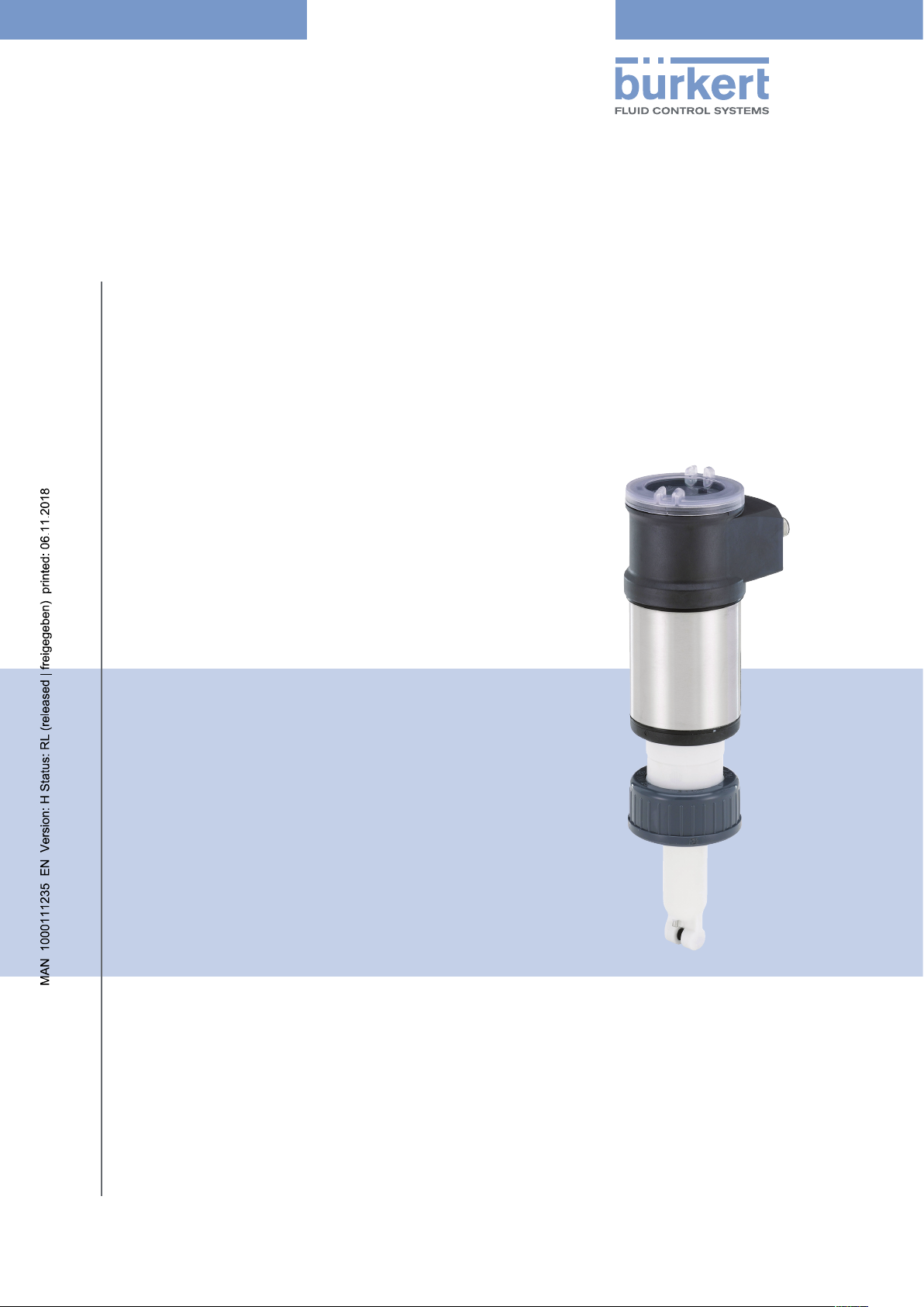
Type 8222
ELEMENT
Conductivity meter
Leitfähigkeits-Messgerät
Conductivimètre
Operating Instructions
Bedienungsanleitung
Manuel d‘utilisation

We reserve the right to make technical changes without notice.
Technische Änderungen vorbehalten.
Sous réserve de modifications techniques.
© Bürkert SAS, 2008 - 2018
Operating Instructions 1810/5_EU-ML 00560330 / Original_FR

Type 8222 ELEMENT
Contents
1 ABOUT THE OPERATING INSTRUCTIONS ...........................................................................................................................7
1.1 Definition of the word “device” .......................................................................................................................................7
1.2 Validity of the Operating Instructions .........................................................................................................................7
1.3 Symbols used ..........................................................................................................................................................................7
2 INTENDED USE ....................................................................................................................................................................................8
3 BASIC SAFETY INFORMATION ....................................................................................................................................................8
4 GENERAL INFORMATION .............................................................................................................................................................10
4.1 Manufacturer’s address and international contacts .........................................................................................10
4.2 Warranty conditions ...........................................................................................................................................................10
4.3 Information on the internet ............................................................................................................................................10
5 DESCRIPTION ....................................................................................................................................................................................11
5.1 Area of application .............................................................................................................................................................11
5.2 General description ...........................................................................................................................................................11
5.2.1 Structure of the device ......................................................................................................................11
5.2.2 Conductivity sensor ...........................................................................................................................11
5.3 Description of the rating plate .....................................................................................................................................12
6 TECHNICAL DATA .............................................................................................................................................................................13
6.1 Conditions of use ................................................................................................................................................................13
6.2 Conformity to standards and directives .................................................................................................................13
6.2.1 Conformity to the Pressure Equipment Directive ........................................................................13
6.2.2 UL certification .................................................................................................................................... 14
6.3 Dimensions of the device ...............................................................................................................................................14
6.4 Material data ..........................................................................................................................................................................14
6.5 Fluid data .................................................................................................................................................................................15
6.6 Sensor specifications .......................................................................................................................................................17
6.7 Electrical data .......................................................................................................................................................................17
6.8 Data of connectors and cables....................................................................................................................................18
7 ASSEMBLY ...........................................................................................................................................................................................19
English
3

Type 8222 ELEMENT
7.1 Safety instructions .............................................................................................................................................................19
7.2 Removing the cover ...........................................................................................................................................................19
7.3 Mounting the cover ............................................................................................................................................................20
7.4 Mounting the display module .......................................................................................................................................20
7.5 Removing the display module .....................................................................................................................................21
8 INSTALLATION ...................................................................................................................................................................................22
8.1 Safety instructions .............................................................................................................................................................22
8.2 Installation onto the pipe ................................................................................................................................................23
8.3 Wiring .........................................................................................................................................................................................24
8.3.1 Assembling the male or female connector (accessories) ......................................................... 24
8.3.2 Making the installation equipotential ..............................................................................................25
8.3.3 Wiring a version with a single M12 fixed connector ..................................................................26
8.3.4 Wiring a version with 2 M12 fixed connectors ............................................................................ 28
9 OPERATING AND COMMISSIONING .....................................................................................................................................31
9.1 Safety instructions .............................................................................................................................................................31
9.2 Knowing the operating levels .......................................................................................................................................31
9.3 Using the navigation button ..........................................................................................................................................32
9.4 Using the dynamic functions ........................................................................................................................................34
9.5 Entering a numerical value (example) .....................................................................................................................34
9.6 Browsing in a menu (example) ...................................................................................................................................34
9.7 Knowing the display ..........................................................................................................................................................35
9.7.1 Knowing the icons and LEDs ..........................................................................................................35
9.7.2 Knowing the display at the power-up of the device ...................................................................36
9.8 Knowing the Process level ............................................................................................................................................36
9.9 Accessing the Configuration level .............................................................................................................................37
9.10 Knowing the structure of the menus on the Configuration level ..............................................................38
9.11 Knowing the Parameters Menu ...................................................................................................................................41
9.11.1 Transferring data from one device to another .............................................................................. 41
9.11.2 Setting the date and time .................................................................................................................42
9.11.3 Modifying the PARAM menu access code ...................................................................................42
9.11.4 Restoring the default parameters of the Process level and the outputs ............................... 43
4
English
Type 8222 ELEMENT
9.11.5 Setting the data displayed in the Process level ..........................................................................43
9.11.6 Displaying of the lowest and highest values measured .............................................................44
9.11.7 Setting the display contrast and brightness ................................................................................45
9.11.8 Choosing the output wiring mode ..................................................................................................45
9.11.9 Setting the parameters of the current outputs ............................................................................46
9.11.10 Setting the parameters of the transistor outputs ........................................................................47
9.11.11 Choosing the type of temperature compensation ......................................................................48
9.12 Knowing the Calibration menu ....................................................................................................................................49
9.12.1 Activating/deactivating the Hold function ..................................................................................... 49
9.12.2 Modifying the Calibration menu access code .............................................................................50
9.12.3 Adjusting the current outputs .......................................................................................................... 50
9.12.4 Calibrating the conductivity sensor ................................................................................................51
9.12.5 Entering an offset for the temperature measurement ................................................................54
9.13 Knowing the Diagnostic menu ....................................................................................................................................54
9.13.1 Modifying the Diagnostic menu access code ..............................................................................54
9.13.2 Monitoring the fluid conductivity ..................................................................................................... 54
9.13.3 Monitoring the polarisation slope ...................................................................................................55
9.13.4 Monitoring the fluid temperature ..................................................................................................... 56
9.14 Knowing the Test menu ...................................................................................................................................................57
9.14.1 Modifying the Test menu access code .......................................................................................... 57
9.14.2 Checking the outputs functions ......................................................................................................58
9.14.3 Checking the outputs behaviour .....................................................................................................58
9.15 Knowing the Information menu ...................................................................................................................................59
9.15.1 Reading the cause of events linked to icons ...............................................................................59
9.15.2 Reading the software versions ........................................................................................................59
9.15.3 Reading some identification informations of the device ............................................................59
10 MAINTENANCE AND TROUBLESHOOTING .......................................................................................................................60
10.1 Safety instructions .............................................................................................................................................................60
10.2 Cleaning of the device .....................................................................................................................................................60
10.3 Solving a problem ..............................................................................................................................................................61
English
5

Type 8222 ELEMENT
11 ACCESSORIES ..................................................................................................................................................................................65
12 PACKAGING, TRANSPORT ..........................................................................................................................................................65
13 STORAGE ..............................................................................................................................................................................................65
14 DISPOSAL OF THE DEVICE ........................................................................................................................................................66
6
English
Type 8222 ELEMENT
About the Operating Instructions
1 ABOUT THE OPERATING INSTRUCTIONS
The Operating Instructions describe the entire lifecycle of the device. Please keep the Operating Instructions in a
safe place, accessible to all users and any new owners.
The Operating Instructions contains important safety information.
Failure to comply with these instructions can lead to hazardous situations.
▶ The Operating Instructions must be read and understood.
1.1 Definition of the word “device”
The word “device” used within these Operating Instructions refers to the Type 8222 ELEMENT conductivity meter.
1.2 Validity of the Operating Instructions
The Operating Instructions are valid for the devices from the version V2.
These informations are available on the rating plate, see chap. 5.3.
1.3 Symbols used
danger
Warns you against an imminent danger.
▶ Failure to observe this warning can result in death or in serious injury.
Warning
Warns you against a potentially dangerous situation.
▶ Failure to observe this warning can result in serious injury or even death.
caution
Warns you against a possible risk.
▶ Failure to observe this warning can result in substantial or minor injuries.
notice
Warns against material damage.
Indicates additional information, advice or important recommendations.
Refers to information contained in the Operating Instructions or in other documents.
▶ Indicates an instruction to be carried out to avoid a danger, a warning or a possible risk.
→ Indicates a procedure to be carried out.
Indicates the result of a specific instruction.
English
7
Type 8222 ELEMENT
Intended use
2 INTENDED USE
Use of the device that does not comply with the instructions could present risks to people, nearby
installations and the environment.
The device is intended for the measurement of the conductivity in liquids.
▶ Protect this device against electromagnetic interference, ultraviolet rays and, when installed outdoors, the
effects of climatic conditions.
▶ Use this device in compliance with the characteristics and commissioning and use conditions specified in the
contractual documents and in the Operating Instructions.
▶ Never use this device for security applications.
▶ Use this device only if in perfect working order.
▶ Requirements for the safe and proper operation of the device are proper transport, storage and installation, as
well as careful operation and maintenance.
▶ Only use the device as intended.
3 BASIC SAFETY INFORMATION
This safety information does not take into account any contingencies or occurrences that may arise during installation, use and maintenance of the device.
The operating company is responsible for the respect of the local safety regulations including staff safety.
Danger due to electrical voltage.
▶ Disconnect the electrical power for all the conductors and isolate it before carrying out work on the system.
▶ If the device is installed either in a wet environment or outdoors, all the electrical voltages must be of max.
35 V DC.
▶ All equipment connected to the device must be double insulated with respect to the mains according to the
standard IEC 61010-1:2010.
▶ Observe all applicable accident protection and safety regulations for electrical equipment.
Danger due to high pressure in the installation.
▶ Stop the circulation of fluid, cut off the pressure and drain the pipe before loosening the process connections.
Danger due to high fluid temperatures.
▶ Use safety gloves to handle the device.
▶ Stop the circulation of fluid and drain the pipes before loosening the process connections.
Danger due to the nature of the fluid.
▶ Respect the regulations on accident prevention and safety relating to the use of dangerous fluids.
8
English
Type 8222 ELEMENT
Intended use
Various dangerous situations.
To avoid injury take care:
▶ not to use this device in explosive atmospheres.
▶ not to use this device in an environment incompatible with the materials from which it is made.
▶ not to use fluid that is incompatible with the materials of which the device is made.
▶ not to subject the device to mechanical loads.
▶ not to make any modifications to the device.
▶ to prevent any unintentional power supply switch-on.
▶ to carry out the installation and maintenance work by qualified and skilled staff with the appropriate tools.
▶ to guarantee a set or controlled restarting of the process after a power supply interruption.
▶ to observe the general technical rules during the planning and use of the device.
NOTICE
The device may be damaged by the fluid in contact with.
▶ Systematically check the chemical compatibility of the component materials of the device and the fluids likely
to come into contact with the materials (for example: alcohols, strong or concentrated acids, aldehydes, alkaline compounds, esters, aliphatic compounds, ketones, halogenated aromatics or hydrocarbons, oxidants and
chlorinated agents).
NOTICE
Elements / Components sensitive to electrostatic discharges
This device contains electronic components that are sensitive to electrostatic discharges. They may be
damaged if they are touched by an electrostatically charged person or object. In the worst case scenario, these
components are instantly destroyed or go out of order as soon as they are activated.
▶ To minimise or even avoid all damage due to an electrostatic discharge, take all the precautions described in
the EN 61340-5-1 norm.
▶ Also make sure that you do not touch any of the live electrical components.
English
9
Type 8222 ELEMENT
General information
4 GENERAL INFORMATION
4.1 Manufacturer’s address and international contacts
To contact the manufacturer of the device, use following address:
Bürkert SAS
Rue du Giessen
BP 21
F-67220 TRIEMBACH-AU-VAL
You may also contact your local Bürkert sales office.
The addresses of our international sales offices are available on the internet at: www.burkert.com
4.2 Warranty conditions
The condition governing the legal warranty is the conforming use of the device in observance of the operating
conditions specified in the Operating Instructions.
4.3 Information on the internet
You can find the Operating Instructions and technical data sheets for Type 8222 at: www.burkert.com
10
English

Type 8222 ELEMENT
Description
5 DESCRIPTION
5.1 Area of application
The Type 8222 ELEMENT conductivity meter is intended for the measurement of the conductivity.
Thanks to two fully adjustable transistor outputs, the device can be used to switch a solenoid valve, activate an
alarm and, thanks to one or two 4...20 mA current outputs, establish one or two control loops.
5.2 General description
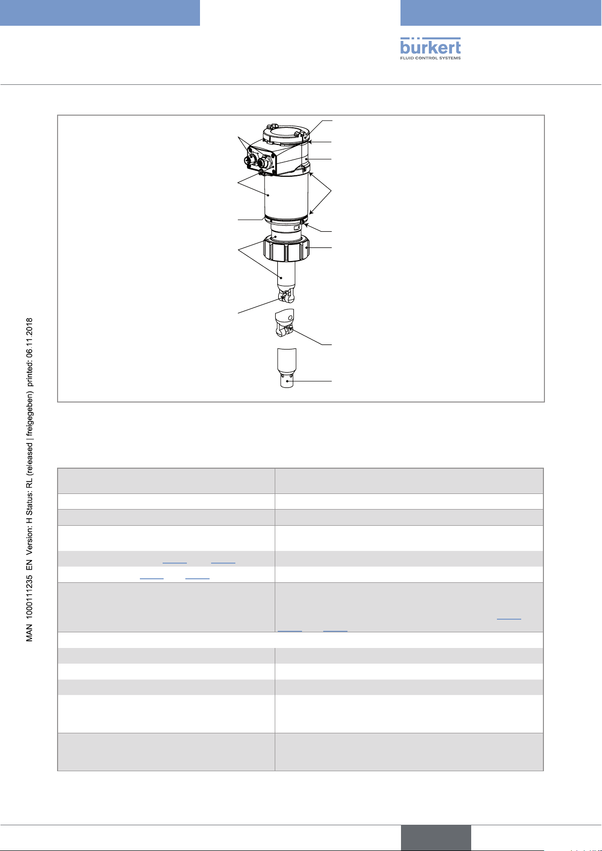
5.2.1 Structure of the device
The device comprises:
• A sensor for measuring physical parameters, comprising:
- 2 electrodes which measure an impedance in Ohm
- a Pt1000 temperature probe measuring a resistance.
• An acquisition / conversion module for the process values measured:
- acquisition of the impedance measured in Ohm
- conversion of the measured impedance into conductivity units
- acquisition of the resistance measured and conversion into temperature
• an electrical housing which can include a display module. The display module has a navigation button used
to read and/or configure the parameters of the device. The display module is available as an accessory (see
chap. 11).
One version of the device with 2 transistor outputs and a 4...20 mA output operates on a 2-wire system and
requires a power supply of 14...36 V DC. For such a version, electrical connection is done via an M12, 5-point,
male fixed connector.
One version of the device with 2 transistor outputs and two 4...20 mA outputs operates on a 3-wire system and
requires a power supply of 12...36 V DC. For such a version, electrical connection is done via an M12, 5-point,
male fixed connector and an M12, 5-point, female fixed connector.
5.2.2 Conductivity sensor
The device is fitted with a sensor measuring the conductivity. The sensor is pined together with the electronic
module and cannot be dismantled.
The sensor itself comprises a Pt1000 temperature probe and 2 electrodes (in stainless steel for sensors with a
C constant of 0.01 or 0.1, in graphite for sensors with a C constant of 1.0).
The conductivity of a fluid is the capacity of this fluid to conduct electrical current thanks to the ions in the fluid.
An alternating voltage is applied to the electrode terminals: the current measured is directly proportional to the
conductivity of the solution.
English
11
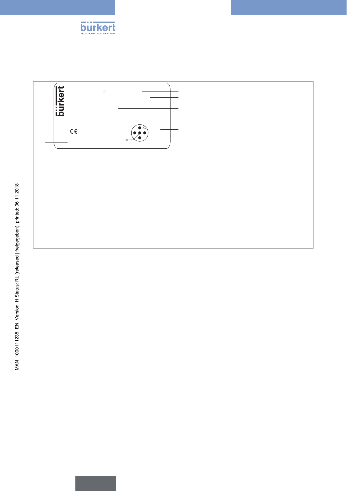
5.3 Description of the rating plate
8222 Conductivity Transmitter V2
1
8
10
12
11
Type 8222 ELEMENT
Description
Supply: 14-36V 40W Max
Output: 1x 4-20mA 2x Trans. 1A Max
Cell: C 1,00 Range 5-10000 µS/cm
Process: Temp 0/50°C
PN 16 Bar
Made in France
IP65-IP67 W41MT
9
Fig. 1 : Rating plate of the device (example)
S-N: 2691
00559610
2:NPN/PNP1
3:0V
4:NPN/PNP2
1:V+
1. Type of the device, parameter measured and
2
version
3
4
2. Electrical power supply and power
5
6
consumption
3. Output specifications
7
4. Cell constant and measuring range of the
conductivity
5. Temperature range of the fluid
6. Nominal pressure of the fluid
7. Allocation of the pins on the M12 fixed
connectors
8. Construction code
9. Article number
10. Serial number
11. Conformity marking
12. Protection rating
12
English
Type 8222 ELEMENT
Technical data
6 TECHNICAL DATA
6.1 Conditions of use
Ambient temperature
Air humidity
Protection rating
according to IEC / EN 60529
Operating conditions
Equipment mobility
Degree of pollution
(UL and CSA recognized version)
Installation category (UL and
CSA recognized version)
Max. height above sea level
–10...+60 °C
< 85 %, non condensing
IP65 and IP67 with connectors plugged in and tightened and electronic
module cover fully sealed
Continuous
Fixed
Degree 2 according to EN 61010-1
Category I according to UL 61010-1
2000 m
6.2 Conformity to standards and directives
The applied standards, which verify conformity with the EU directives, can be found on the EU-type examination
certificate and/or the EU declaration of conformity (if applicable).
6.2.1 Conformity to the Pressure Equipment Directive
→ Make sure the device materials are compatible with the fluid.
→ Make sure the pipe DN and the PN are adapted for the device.
The device conforms to Article 4, Paragraph 1 of the Pressure Equipment Directive 2014/68/EU under the following conditions:
• Device used on a piping (PS = maximum admissible pressure; DN = nominal diameter of the pipe)
Type of fluid Conditions
Fluid group 1, Article 4, Paragraph 1.c.i DN≤25
Fluid group 2, Article 4, Paragraph 1.c.i
Fluid group 1, Article 4, Paragraph 1.c.ii
Fluid group 2, Article 4, Paragraph 1.c.ii
• Device used on a vessel (PS = maximum admissible pressure)
Type of fluid Conditions
Fluid group 1, Article 4, Paragraph 1.a.i PS ≤ 200 bar
Fluid group 2, Article 4, Paragraph 1.a.i PS ≤ 1000 bar
Fluid group 1, Article 4, Paragraph 1.a.ii PS ≤ 500 bar
Fluid group 2, Article 4, Paragraph 1.a.ii PS ≤ 1000 bar
DN≤32
or PSxDN≤1000
DN≤25
or PSxDN≤2000
DN≤200
or PS≤10
or PSxDN≤5000
13
English

Measuring
Equipment
EXXXXXX
®
Type 8222 ELEMENT
Technical data
6.2.2 UL certification
The devices with variable key PU01 or PU02 are UL certified devices and comply also with the following
standards:
• UL 61010-1
• CAN/CSA-C22.2 n°61010-1
Identification on the device Certification Variable key
UL recognized PU01
UL listed PU02
6.3 Dimensions of the device
→ Please refer to the technical data sheets related to the device available at: www.burkert.com
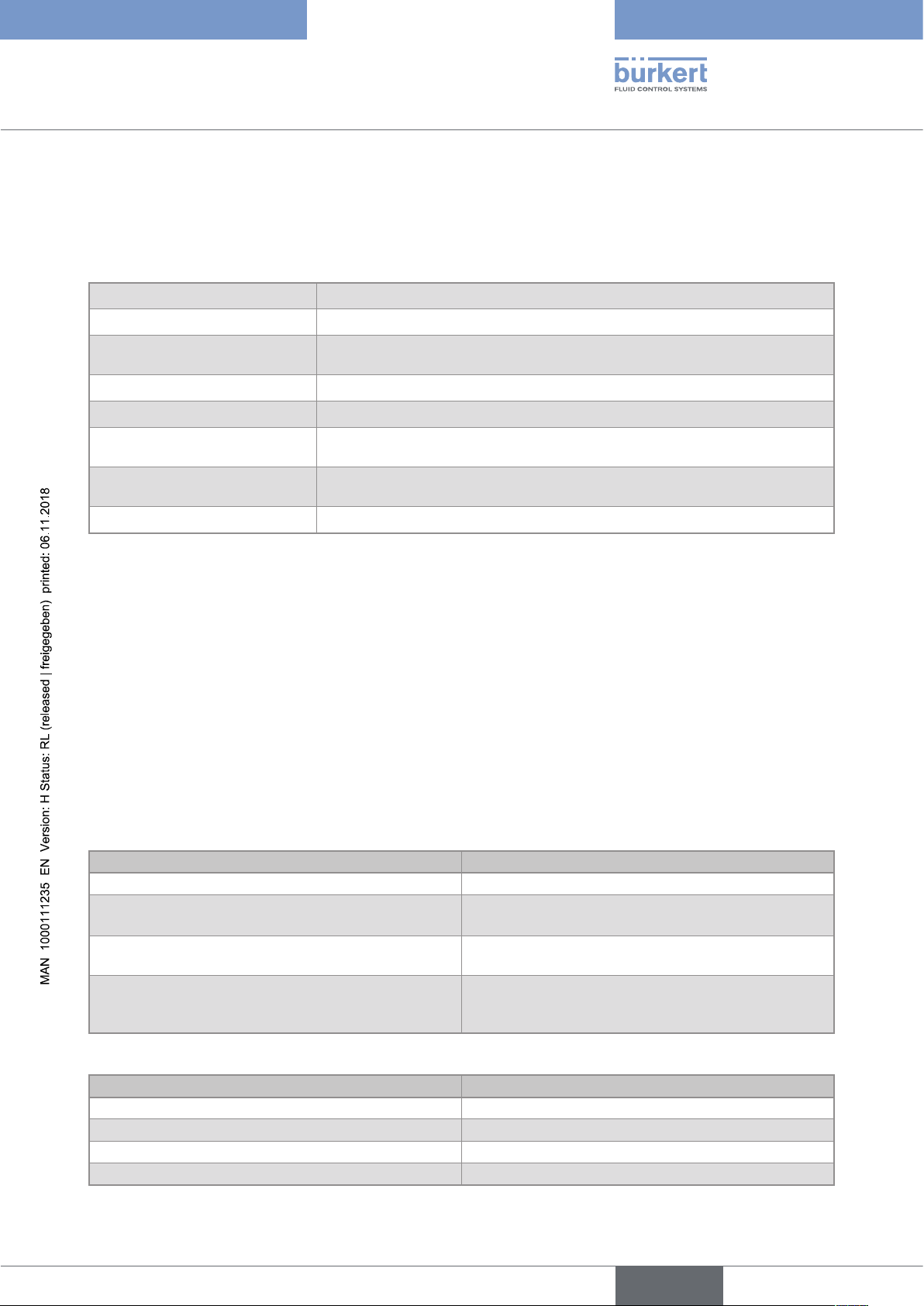
6.4 Material data
Part Material
Box / seals stainless steel 1.4561, PPS / EPDM
Cover / seal PC / silicone
Display module PC / PBT
M12 fixed connector nickel-plated brass (stainless steel on request)
Fixed connector holder stainless steel 1.4404 (316L)
Screws stainless steel
Tightening nut PVC or PVDF
Conductivity sensor PVDF (in contact with the fluid)
Pt1000 stainless steel 1.4571 (316Ti) (in contact with the fluid)
Electrodes
• sensor C=1 • graphite
• sensor C=0.1 or C=0.01 • stainless steel 1.4571 (316Ti)
14
English
Type 8222 ELEMENT
Technical data
Nickel-plated brass
(or stainless steel)
PC
Silicone
PPS
Stainless steel
Electrodes: graphite (C=1)
Fig. 2 : Materials of the device
6.5 Fluid data
PPS
PVDF
EPDM
PPS
PVC or PVDF
Temperature sensor: stainless steel
316Ti (C=1)
Stainless steel 316Ti (C=0.1 or 0.01)
Pipe diameter
Type of fitting
Nut between the 8222 and the fitting
Max. fluid temperature
• with a PVDF nut (see Fig. 3 and Fig. 5) • –20...+100 °C
• with a PVC nut (Fig. 3 and Fig. 4) • 0...+50 °C
Max. fluid pressure
Conductivity measurement
• Measurement range • 0,05 µS/cm...10 mS/cm
• Resolution • 1 nS/cm
• Measurement deviation • ±3 % of the measured value
• Recommended min. divergence of the conductivity range associated to the 4...20 mA signal
Temperature probe
DN25 to DN110
(DN15 to DN20 under specific conditions)
Adapter S022
G 1 1/2'' internal thread
The fluid temperature may be restricted by the pressure of
the fluid and the material of the S022 adapter
PN16
The fluid pressure may be restricted by the temperature of
the fluid and the material of the adapter S022 (see Fig. 3,
Fig. 4 and Fig. 5)
• 2 % of the full scale (e.g. for the sensor with C=0.1: range
from 100...104 µS corresponds to the 4...20 mA output
current)
Pt1000 integrated in the conductivity sensor
English
15
Temperature measurement
• Measurement range • –40...+130 °C
• Resolution • 0.1 °C
• Measurement deviation • ±1 °C
• Recommended min. divergence of the temperature range associated to the 4...20 mA signal
• 10 °C
(e.g. range 10...20 °C corresponds to the 4...20 mA output
current)
Temperature compensation
• none
• or according to a predefined graph (NaCl or ultra pure
water)
• or according to a graph defined especially for your process
Type 8222 ELEMENT
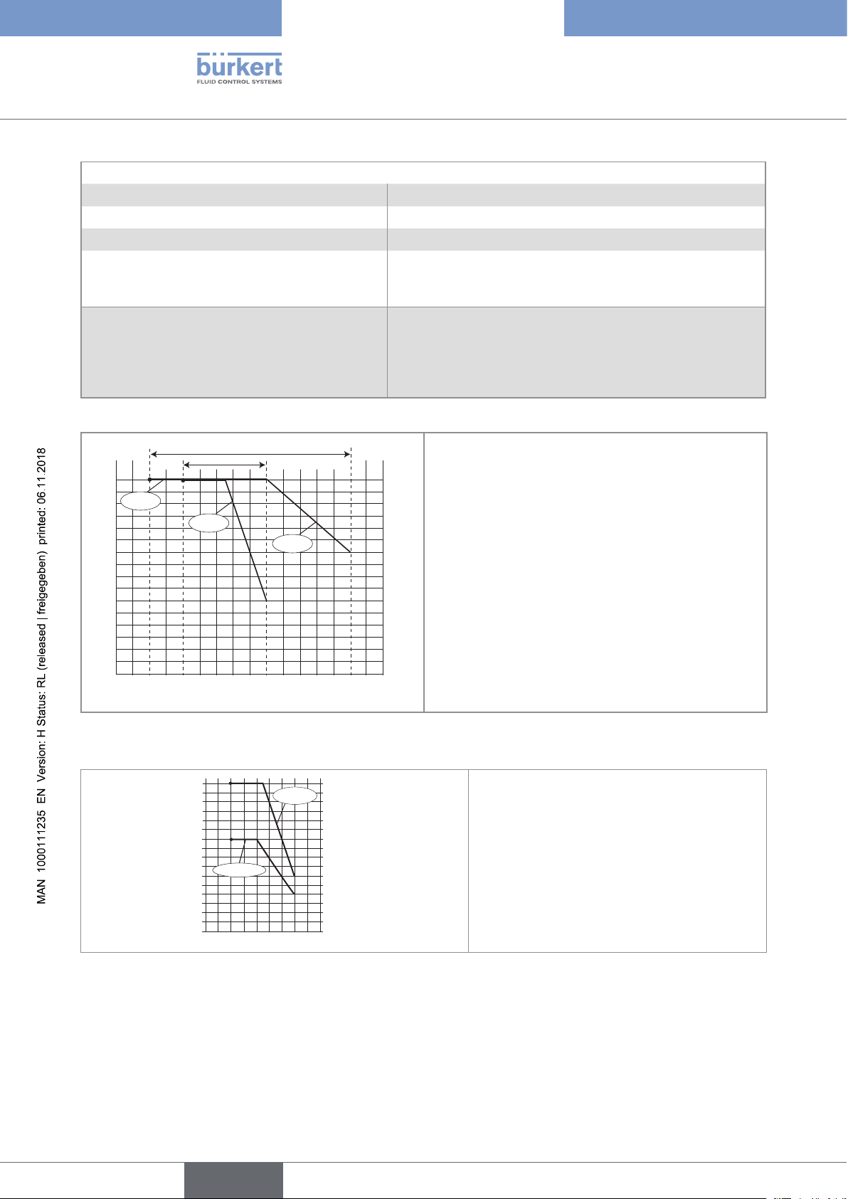
Technical data
• A: application range of a 8222 with a PVDF nut
P (psi)
• B: application range of a 8222 with a PVC nut
232
217.6
203
The measures have been made at an ambient tem-
188.6
174
perature of 60 °C
159.6
145
130.6
116
P = Fluid pressure
101.6
87
T = Fluid temperature
72.5
58
43.5
29
14
0
P (bar)
16
15
14
13
12
11
10
A
B
PVDF
PVC
PVDF
9
8
7
6
5
4
3
2
1
0
-20 0 +20 +40 +60 +80 +100 +120
T ( ° C)
Fig. 3 : Fluid temperature / fluid pressure dependency of the 8222 with a PVC or PVDF nut
16
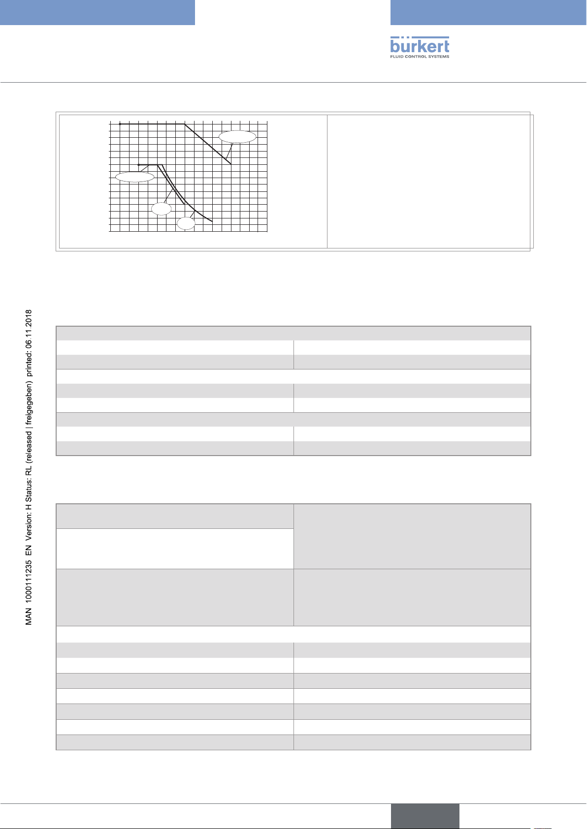
P (bar)
15
14
13
12
11
10
9
8
7
6
5
4
3
2
1
0
-20
PVC + PP
Metal
0 +20 +40 +60
232
217.6
203
188.6
174
159.6
145
130.6
116
101.6
87
72.5
58
43.5
29
14
0
T (°C)
P (psi)
P = Fluid pressure
T = Fluid temperature
16
Fig. 4 : Fluid temperature / fluid pressure dependency of the 8222 with a PVC nut and a metal, PVC or PP S022
adapter.
English
Type 8222 ELEMENT
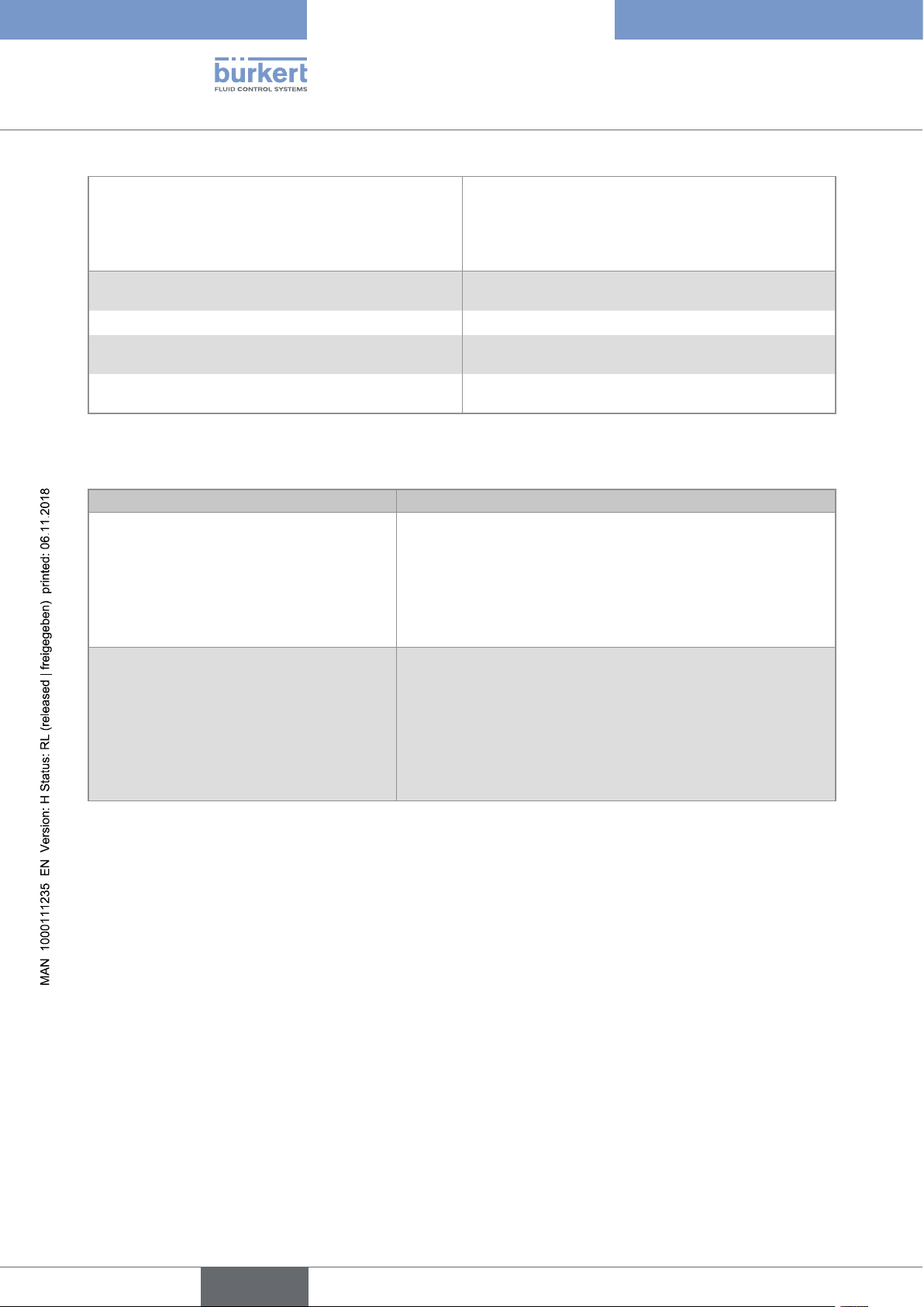
Technical data
P (bar)
16
15
14
13
12
11
10
9
8
PVC + PP
7
6
5
4
3
2
1
0
-20 0 +20 +40 +60 +80 +100 +140
PVC
PP
Metal
+120
232
217.6
203
188.6
174
159.6
145
130.6
116
101.6
87
72.5
58
43.5
29
14
0
P (psi)
P = Fluid pressure
T = Fluid temperature
T (°C)
Fig. 5 : Fluid temperature / fluid pressure dependency of the 8222 with a PVDF nut and a metal, PVC or PP S022
adapter.
6.6 Sensor specifications
Conductivity sensor C=0.01
• Measurement range • 0.05...20 µS/cm
• Type of fluid • ultra-pure water, pure water
Conductivity sensor C=0.1
• Measurement range • 0.5...200 µS/cm
• Type of fluid
Conductivity sensor C=1
• Measurement range • 5 µS/cm to 10 mS/cm
• Type of fluid
• pure water, industrial wastewater
• industrial wastewater, wastewater
6.7 Electrical data
14...36 V DC power supply
version with 2 or 3 outputs (2 wires)
12...36 V DC power supply
version with 4 outputs (3 wires)
Specifications of the power source (not supplied)
of the UL devices
Current consumption
• Version with 3 outputs • 25 mA max. (at 14 V DC)
• Version with 4 outputs • 5 mA max. (at 12 V DC)
Current consumption, with loads on the transistors
Power consumption
Protection against polarity reversal
Protection against voltage spikes
Protection against short circuits
• Connection to main supply: permanent (through
external SELV and through LPS power supply)
• filtered and regulated
• oscillation rate: ±10 %
• Limited power source according to UL / EN 60950-1
standards
• or limited energy circuit according to
UL / EN 61010-1, Paragraph 9.4
1 A max.
40 W max.
yes
yes
yes, transistor outputs
17
English
Type 8222 ELEMENT
Technical data
Transistor output
NPN (/sink) or PNP (/source) (depending on software
setting), open collector, 700 mA max., 0.5 A max. per
transistor if both transistor outputs are wired.
NPN output: 0.2...36 V DC
PNP output: supply voltage
Current output
4...20 mA, sink ("NPN sink") or source ("PNP source")
(depending on software setting)
• Response time (10...90 %) • 150 ms (default value)
• Version with 1 current output • max. loop impedance: 1100W at 36 V DC, 610W at
24 V DC, 180W at 14 V DC
• Version with 2 current outputs • max. loop impedance: 1100W at 36 V DC, 610W at
24 V DC, 100W at 12 V DC
6.8 Data of connectors and cables
Number of fixed connectors Type of connector
1 male M12 fixed connector 5-pin female M12 connector (not supplied).
For the M12 connector with article number 917116, use a
shielded cable:
• diameter: 3...6.5 mm
2
1 male M12 fixed connector and 1 female
M12 fixed connector
• wire cross section: max. 0.75 mm
5-pin female M12 connector (not supplied) and 5-pin male M12
connector (not supplied).
For the M12 connector with article number 917116, use a
shielded cable:
• diameter: 3...6.5 mm
• wire cross section: max. 0.75 mm
2
18
English
Type 8222 ELEMENT
Assembly
7 ASSEMBLY
7.1 Safety instructions
Warning
Risk of injury due to non-conforming assembly.
▶ The device must only be assembled by qualified and skilled staff with the appropriate tools.
Risk of injury due to unintentional switch on of power supply or uncontrolled restarting of the
installation.
▶ Avoid unintentional activation of the installation.
▶ Guarantee a set or controlled restarting of the process subsequent to any intervention on the device.
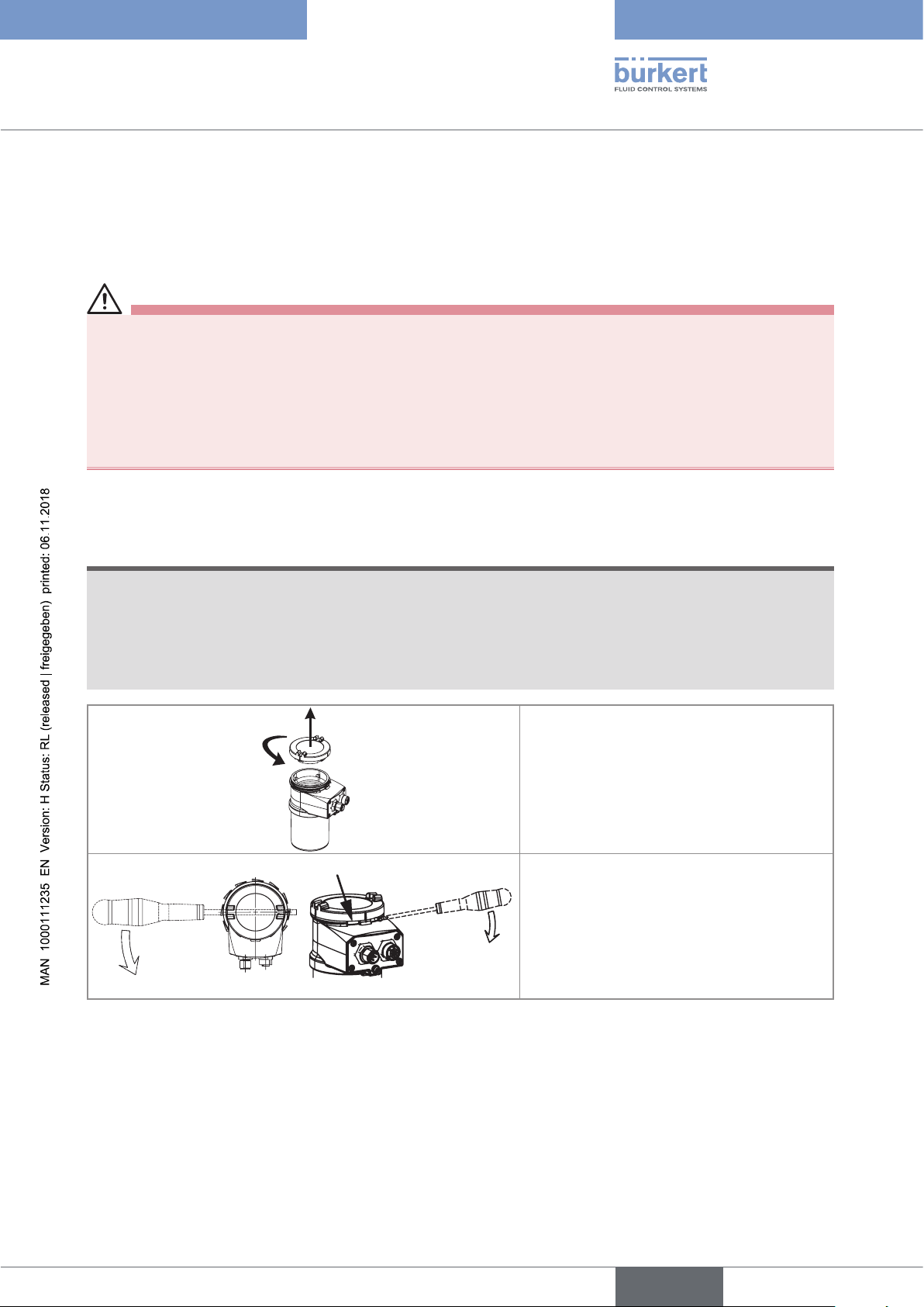
7.2 Removing the cover
NOTICE
The tightness of the device is not guaranteed when the cover is removed.
▶ Prevent the projection of liquid inside the housing.
The device may be damaged if a metal component comes into contact with the electronics.
▶ Prevent contact of the electronics with a metallic item.
2
1
→ [1] Turn the cover counterclockwise with
an angle of about 15° to unlock it.
→ [2] Remove the cover.
In case, the cover grips to the housing:
→ Use an appropriate tool to unlock the
cover, taking care not to scratch the glass.
→ Insert an appropriate tool into the groove
of the housing.
Fig. 6 : Removing the cover
→ Lever the cover up.
19
English
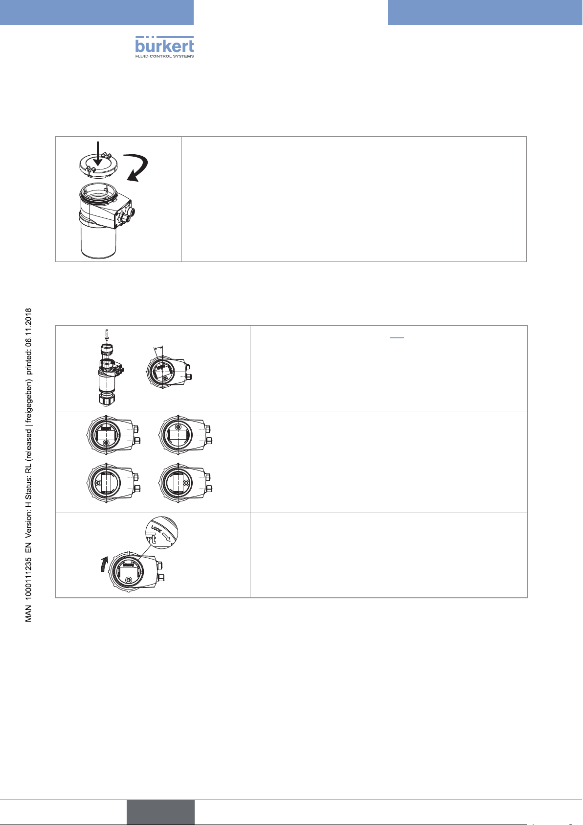
7.3 Mounting the cover
1
→ Check that there is a seal on the housing and that it is not damaged. Replace
it if necessary.
2
→ Grease the seal if necessary, using a component compatible with the seal
material.
→ [1] Set the cover to ensure that the 4 grooves of the cover match with the 4
pins of the housing.
→ [2] Turn the cover clockwise with an angle of about 15° to lock it.
Fig. 7 : Mounting the cover
7.4 Mounting the display module
Type 8222 ELEMENT
Assembly
20°
a)
b)
Fig. 8 : Mounting the display module
c)
d)
→ Remove the cover (see chap. 7.2).
→ Set the display module at an angle of ca. 20° in relation to the
desired position.
The module can be fitted in 4 different positions, at 90° intervals.
→ Fully push in the module and turn clockwise to lock it.
20
English
Type 8222 ELEMENT
Assembly
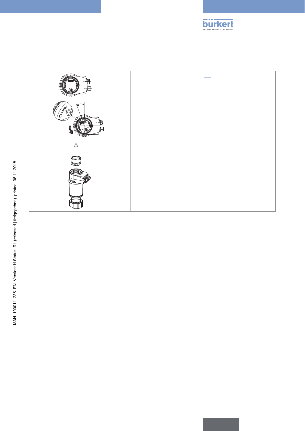
7.5 Removing the display module
→ Remove the cover (see chap. 7.2).
→ Turn the module counter clockwise by ca. 20°.
20°
Fig. 9 : Removing the display module
Once unlocked, the module is raised slightly by the spring action.
→ Remove the module from its housing.
English
21
 Loading...