

Page 1

MultivaporTM P-6/P-12
Operation Manual
093156 en
Page 2

Page 3

Table of contents
Table of contents
1 About this manual . . . . . . . . . . . . . . . . . . . . . . . . . . . . . . . . . . . . . . .6
1.1 Reference documents. . . . . . . . . . . . . . . . . . . . . . . . . . . . . . . . . .6
1.2 Trademarks . . . . . . . . . . . . . . . . . . . . . . . . . . . . . . . . . . . . . . . 6
1.3 Abbreviations . . . . . . . . . . . . . . . . . . . . . . . . . . . . . . . . . . . . . . 7
2 Safety. . . . . . . . . . . . . . . . . . . . . . . . . . . . . . . . . . . . . . . . . . . . . .8
2.1 User qualification . . . . . . . . . . . . . . . . . . . . . . . . . . . . . . . . . . . . 8
2.2 Proper use . . . . . . . . . . . . . . . . . . . . . . . . . . . . . . . . . . . . . . . 8
2.3 Improper use . . . . . . . . . . . . . . . . . . . . . . . . . . . . . . . . . . . . . . 8
2.4 Safety warnings and safety signals used in this manual . . . . . . . . . . . . . . . . . 9
2.5 Product safety. . . . . . . . . . . . . . . . . . . . . . . . . . . . . . . . . . . . . 11
2.5.1 Instrument-related hazards . . . . . . . . . . . . . . . . . . . . . . . . . . . . . . 11
2.5.2 Other hazards . . . . . . . . . . . . . . . . . . . . . . . . . . . . . . . . . . . . . 12
2.5.3 Personal protective equipment . . . . . . . . . . . . . . . . . . . . . . . . . . . . 12
2.5.4 Safety elements . . . . . . . . . . . . . . . . . . . . . . . . . . . . . . . . . . . . 13
2.6 General safety rules . . . . . . . . . . . . . . . . . . . . . . . . . . . . . . . . . . 13
3 Technical data . . . . . . . . . . . . . . . . . . . . . . . . . . . . . . . . . . . . . . . . 14
3.1 Scope of delivery . . . . . . . . . . . . . . . . . . . . . . . . . . . . . . . . . . . 14
3.1.1 Instrument configurations . . . . . . . . . . . . . . . . . . . . . . . . . . . . . . . 14
3.1.2 Ordering matrix . . . . . . . . . . . . . . . . . . . . . . . . . . . . . . . . . . . . 17
3.1.3 Standard accessories . . . . . . . . . . . . . . . . . . . . . . . . . . . . . . . . . 20
3.1.4 Standard accessory glassware . . . . . . . . . . . . . . . . . . . . . . . . . . . . 22
3.1.5 Optional accessories . . . . . . . . . . . . . . . . . . . . . . . . . . . . . . . . . 23
3.2 Materials used. . . . . . . . . . . . . . . . . . . . . . . . . . . . . . . . . . . . . 24
3.3 Technical data overview . . . . . . . . . . . . . . . . . . . . . . . . . . . . . . . . 26
3.4 Solvent table . . . . . . . . . . . . . . . . . . . . . . . . . . . . . . . . . . . . . 27
Read this manual carefully before installing and running your system and note the safety precautions
in chapter 2 in particular. Store the manual in the immediate vicinity of the instrument, so that it can be
consulted at any time.
No technical modifications may be made to the instrument without the prior written agreement of
BUCHI. Unauthorized modifications may affect the system safety or result in accidents.
This manual is copyright. Information from it may not be reproduced, distributed, or used for competitive purposes, nor made available to third parties. The manufacture of any component with the aid of
this manual without prior written agreement is also prohibited.
The English manual is the original language version and serves as basis for all translations
into other languages. Other language versions can be downloaded at www.buchi.com.
3 Multivapor™ Operation Manual, Version E
Page 4

Table of contents
4 Description of function . . . . . . . . . . . . . . . . . . . . . . . . . . . . . . . . . . . 28
4.1 Functional principle of the Multivapor . . . . . . . . . . . . . . . . . . . . . . . . . 28
4.1.1 Functional principle of the stand-alone unit . . . . . . . . . . . . . . . . . . . . . . 28
4.1.2 Functional principle of the Multivapor-Rotavapor edition. . . . . . . . . . . . . . . . 29
4.1.3 Controls of the Multivapor (stand-alone) . . . . . . . . . . . . . . . . . . . . . . . . 30
4.1.4 Display of the Multivapor . . . . . . . . . . . . . . . . . . . . . . . . . . . . . . . 30
4.1.5 Rear connections of the Multivapor . . . . . . . . . . . . . . . . . . . . . . . . . . 31
4.2 Multivapor platform . . . . . . . . . . . . . . . . . . . . . . . . . . . . . . . . . . 31
4.3 Crystal rack . . . . . . . . . . . . . . . . . . . . . . . . . . . . . . . . . . . . . . 32
4.4 Sample preparation rack . . . . . . . . . . . . . . . . . . . . . . . . . . . . . . . 32
4.5 Blank adapters (optional) . . . . . . . . . . . . . . . . . . . . . . . . . . . . . . . 33
4.6 PE frits . . . . . . . . . . . . . . . . . . . . . . . . . . . . . . . . . . . . . . . . 33
4.7 Adapter spring . . . . . . . . . . . . . . . . . . . . . . . . . . . . . . . . . . . . 33
4.8 Sample transfer plate . . . . . . . . . . . . . . . . . . . . . . . . . . . . . . . . . 34
4.9 Vacuum cover. . . . . . . . . . . . . . . . . . . . . . . . . . . . . . . . . . . . . 34
4.10 Protective shield (optional). . . . . . . . . . . . . . . . . . . . . . . . . . . . . . . 35
4.11 Condensation (optional) . . . . . . . . . . . . . . . . . . . . . . . . . . . . . . . . 35
4.12 High-boiling solvents - Woulff bottle (optional) . . . . . . . . . . . . . . . . . . . . . 36
4.13 Vacuum solution (optional). . . . . . . . . . . . . . . . . . . . . . . . . . . . . . . 36
4.14 Connection to a rotary evaporator (optional). . . . . . . . . . . . . . . . . . . . . . 37
4.15 Refrigerated receiver (optional) . . . . . . . . . . . . . . . . . . . . . . . . . . . . 37
5 Putting into operation . . . . . . . . . . . . . . . . . . . . . . . . . . . . . . . . . . . . 38
5.1 Installation site. . . . . . . . . . . . . . . . . . . . . . . . . . . . . . . . . . . . . 38
5.2 Electrical connections . . . . . . . . . . . . . . . . . . . . . . . . . . . . . . . . . 38
5.3 Commissioning the Multivapor basic instrument. . . . . . . . . . . . . . . . . . . . 39
5.3.1 Commissioning the crystal rack . . . . . . . . . . . . . . . . . . . . . . . . . . . . 39
5.3.2 Assembling the Woulff bottle (optional) . . . . . . . . . . . . . . . . . . . . . . . . 40
5.3.3 Anti-seismic tie-down . . . . . . . . . . . . . . . . . . . . . . . . . . . . . . . . . 40
5.4 Glass assembly . . . . . . . . . . . . . . . . . . . . . . . . . . . . . . . . . . . . 41
5.4.1 Type S and type C condenser . . . . . . . . . . . . . . . . . . . . . . . . . . . . . 41
5.4.2 Condenser assembly with the refrigerated receiver (optional) . . . . . . . . . . . . . 41
5.5 Tube connections . . . . . . . . . . . . . . . . . . . . . . . . . . . . . . . . . . . 42
5.5.1 Cooling water . . . . . . . . . . . . . . . . . . . . . . . . . . . . . . . . . . . . . 42
5.5.2 Vacuum tubes. . . . . . . . . . . . . . . . . . . . . . . . . . . . . . . . . . . . . 43
5.6 Commissioning the Multivapor-Rotavapor edition . . . . . . . . . . . . . . . . . . . 44
5.7 Functional test. . . . . . . . . . . . . . . . . . . . . . . . . . . . . . . . . . . . . 44
5.7.1 Vacuum tightness test. . . . . . . . . . . . . . . . . . . . . . . . . . . . . . . . . 44
4 Multivapor™ Operation Manual, Version E
Page 5

Table of contents
6 Operation . . . . . . . . . . . . . . . . . . . . . . . . . . . . . . . . . . . . . . . . . . 46
6.1 Settings at the Multivapor platform . . . . . . . . . . . . . . . . . . . . . . . . . . 46
6.1.1 Selecting a preset temperature . . . . . . . . . . . . . . . . . . . . . . . . . . . . 47
6.1.2 Changing/switching off the preset temperature . . . . . . . . . . . . . . . . . . . . 47
6.1.3 Setting the rotational speed . . . . . . . . . . . . . . . . . . . . . . . . . . . . . . 47
6.2 Sample preparation . . . . . . . . . . . . . . . . . . . . . . . . . . . . . . . . . . 48
6.2.1 Heating up the instrument . . . . . . . . . . . . . . . . . . . . . . . . . . . . . . . 48
6.2.2 Sample preparation . . . . . . . . . . . . . . . . . . . . . . . . . . . . . . . . . . 48
6.3 Selecting the distillation conditions . . . . . . . . . . . . . . . . . . . . . . . . . . 50
6.4 Distillation . . . . . . . . . . . . . . . . . . . . . . . . . . . . . . . . . . . . . . . 51
6.5 Optimizing the vacuum conditions (optional). . . . . . . . . . . . . . . . . . . . . . 51
6.5.1 Manual vacuum control and solvent library (V-850/V-855) . . . . . . . . . . . . . . . 51
6.5.2 Pressure gradients (V-855) . . . . . . . . . . . . . . . . . . . . . . . . . . . . . . 52
6.5.3 Automatic distillation (V-855) . . . . . . . . . . . . . . . . . . . . . . . . . . . . . 53
6.6 Optimizing the distillation conditions. . . . . . . . . . . . . . . . . . . . . . . . . . 53
6.7 When the distillation “dies out” . . . . . . . . . . . . . . . . . . . . . . . . . . . . 54
6.8 At the end of a run . . . . . . . . . . . . . . . . . . . . . . . . . . . . . . . . . . 54
7 Maintenance . . . . . . . . . . . . . . . . . . . . . . . . . . . . . . . . . . . . . . . . . 55
7.1 Housing . . . . . . . . . . . . . . . . . . . . . . . . . . . . . . . . . . . . . . . . 55
7.2 Tube connections and joints. . . . . . . . . . . . . . . . . . . . . . . . . . . . . . 55
7.3 Sealing system . . . . . . . . . . . . . . . . . . . . . . . . . . . . . . . . . . . . 55
7.3.1 Cleaning the seals. . . . . . . . . . . . . . . . . . . . . . . . . . . . . . . . . . . 55
7.3.2 Replacing the tube adapter seals . . . . . . . . . . . . . . . . . . . . . . . . . . . 56
7.3.3 Replacing the conical adapter O-rings. . . . . . . . . . . . . . . . . . . . . . . . . 56
7.3.4 Cleaning the vacuum cover and replacing the corresponding O-rings . . . . . . . . . 57
7.4 Crystal rack . . . . . . . . . . . . . . . . . . . . . . . . . . . . . . . . . . . . . . 57
7.5 Glass components . . . . . . . . . . . . . . . . . . . . . . . . . . . . . . . . . . 59
7.6 PE frits (optional) . . . . . . . . . . . . . . . . . . . . . . . . . . . . . . . . . . . 59
8 Troubleshooting . . . . . . . . . . . . . . . . . . . . . . . . . . . . . . . . . . . . . . . 60
8.1 Malfunctions and their remedy. . . . . . . . . . . . . . . . . . . . . . . . . . . . . 60
8.2 Customer service . . . . . . . . . . . . . . . . . . . . . . . . . . . . . . . . . . . 61
9 Shutdown, storage, transport and disposal . . . . . . . . . . . . . . . . . . . . . . . . 62
9.1 Storage and transport . . . . . . . . . . . . . . . . . . . . . . . . . . . . . . . . . 62
9.2 Disposal. . . . . . . . . . . . . . . . . . . . . . . . . . . . . . . . . . . . . . . . 62
9.3 Health and safety clearance form . . . . . . . . . . . . . . . . . . . . . . . . . . . 63
10 Spare parts. . . . . . . . . . . . . . . . . . . . . . . . . . . . . . . . . . . . . . . . . . 64
10.1 Basic instrument . . . . . . . . . . . . . . . . . . . . . . . . . . . . . . . . . . . 64
10.2 Evaporation unit . . . . . . . . . . . . . . . . . . . . . . . . . . . . . . . . . . . . 65
10.3 Adapter sets . . . . . . . . . . . . . . . . . . . . . . . . . . . . . . . . . . . . . 67
10.4 Condenser assemblies . . . . . . . . . . . . . . . . . . . . . . . . . . . . . . . . 68
10.5 Various glass parts . . . . . . . . . . . . . . . . . . . . . . . . . . . . . . . . . . 69
10.6 Miscellaneous . . . . . . . . . . . . . . . . . . . . . . . . . . . . . . . . . . . . . 71
11 Declarations and requirements. . . . . . . . . . . . . . . . . . . . . . . . . . . . . . . 73
11.1 FCC requirements (for USA and Canada) . . . . . . . . . . . . . . . . . . . . . . . 73
11.2 Declaration of conformity . . . . . . . . . . . . . . . . . . . . . . . . . . . . . . . 74
5 Multivapor™ Operation Manual, Version E
Page 6

1 About this manual
This manual describes the Multivapor P-6 and P-12 and provides all information required for its safe
operation and to maintain it in good working order.
It is addressed in particular to laboratory personnel and operators.
NOTE
The symbols pertaining to safety (WARNINGS and ATTENTIONS) are explained in chapter 2.
1.1 Reference documents
For information on the Rotavapor, the vacuum controller and the vacuum pump, please refer to the
corresponding manuals available in English, German, French, Spanish and Italian:
• Rotavapor R-210/215, Operation Manual numbers 93076–93080
• Vacuum Controller, Operating Manual numbers 93081–93085
• Vacuum Pump, Operating Manual numbers 93090–93094
1 About this manual
1.2 Trademarks
The following product names and any registered and unregistered trademarks mentioned in this
manual are used for identification purposes only and remain the exclusive property of their respective
owners:
®
is a registered trademark of Dionex Corporation
ASE
• Multivapor™ is a trademark of BÜCHI Labortechnik AG
• Rotavapor
®
is a registered trademark of BÜCHI Labortechnik AG
6 Multivapor™ Operation Manual, Version E
Page 7

1.3 Abbreviations
Chemicals:
EPDM: Ethylenepropylenedimonomer
FEP: Combination of tetrafluoroethylene and hexafluoropropylene
FFKM: Perfluoro caoutchouc
FKM: Fluoric caoutchouc
PBT: Polybutyleneterephthalate
PE: Polyethylene
PEEK: Polyetheretherketone
PET(P): Polyethyletherphtalate
PETP: Polyethylterephthalate
PFA: Perfluoroalkoxy
PTFE: Polytetrafluoroethylene
PUT: Polyurethane
Miscellaneous:
rpm: revolutions per minute
P+G: PLASTIC+GLAS is a unique protective layer for glass components. It offers improved mechan-
ical rupture resistance and increases protection against broken glass whilst ensuring no sample
is lost in the event of the receiving flask being damaged.
1 About this manual
7 Multivapor™ Operation Manual, Version E
Page 8

2 Safety
This chapter highlights the safety concept of the Multivapor and contains general rules of behavior and
warnings from hazards concerning the use of the product.
The safety of users and personnel can only be ensured if these safety instructions and the safetyrelated warnings in the individual chapters are strictly observed and followed, therefore, the manual
must always be available to all persons performing the tasks described herein.
2.1 User qualification
The instrument may only be used by laboratory personnel or other persons who on account of training
or professional experience have an overview of the dangers which can develop when operating the
instrument.
Personnel without this training or persons who are currently being trained require careful supervision.
The present Operation Manual serves as a basis for training.
2 Safety
2.2 Proper use
The instrument has been designed and built for laboratory use only. It serves for activities associated
with the parallel evaporation of multiple samples by means of heating under vacuum, with or without
regulation by a vacuum controller. The vacuum is typically applied by a PTFE diaphragm vacuum
pump.
Alternatively, the instrument can be used in combination with a rotary evaporator. In this case
the Multivapor serves as an accessory and is connected via an interface to the condenser of the
Rotavapor.
2.3 Improper use
Applications beyond those described above are improper. Furthermore, applications which do not
comply with the technical data are also considered improper. The operator bears the sole risk for any
damages caused by such improper use.
The following applications are expressly forbidden:
• Use of the instrument in rooms which require ex-protected instruments.
• Use as a calibrating instrument for other instruments.
• Preparation of samples which can explode or inflame due to shock, friction, heat or spark formation.
• Use in high pressure situations.
• Processing of hard, brittle and abrasive materials (e.g. stones, sherds, soil samples, etc.) which
may destruct the sample tubes.
• Use of the instrument for digestions (e.g. Kjeldahl).
8 Multivapor™ Operation Manual, Version E
Page 9

2.4 Safety warnings and safety signals used in this manual
DANGER, WARNING, CAUTION and NOTICE are standardized signal words for identifying levels of
hazard seriousness of risks related to personal injury and property damage. All signal words, which are
related to personal injury are accompanied by the general safety sign.
For your safety it is important to read and fully understand the below table with the different signal
words and their definitions!
Sign Signal word Definition Risk level
DANGER
Indicates a hazardous situation which, if not avoided, will result in
death or serious injury.
2 Safety
★★★★
WARNING
CAUTION
NOTICE
no
Supplementary safety information symbols may be placed in a rectangular panel on the left to the
signal word and the supplementary text (see below example).
Space for
supplementary
safety
information
symbols.
Indicates a hazardous situation which, if not avoided, could result
in death or serious injury.
Indicates a hazardous situation which, if not avoided, may result
in minor or moderate injury.
Indicates possible property damage, but no
practices related to personal injury.
!
SIGNAL WORD
Supplementary text, describing the kind and level of hazard / risk seriousness.
• List of measures to avoid the herein described hazard or hazardous situation.
• ...
• ...
(property damage only)
★★★☆
★★☆☆
★☆☆☆
Table of supplementary safety information symbols
The below reference list incorporates all safety information symbols used in this manual and their
meaning.
Symbol Meaning
General warning
Electrical hazard
9 Multivapor™ Operation Manual, Version E
Page 10

Symbol Meaning
Explosive gases, explosive environment
Harmful to life-forms
Hot item, hot surface
Explosive substance
2 Safety
Device damage
Inhalation of substances
Flammable substances
Fragile items / content
Do not dispose of in household trash
Wear protective mask
Wear laboratory coat
10 Multivapor™ Operation Manual, Version E
Page 11

2 Safety
Symbol Meaning
Wear protective goggles
Wear protective gloves
Additional user information
Paragraphs starting with NOTE transport helpful information for working with the device / software or
its supplementaries. NOTEs are not related to any kind of hazard or damage (see example below).
NOTE
Useful tips for the easy operation of the instrument / software.
2.5 Product safety
The Multivapor is designed and built in accordance with current state-of-the-art technology, however,
risks to users, property, and the environment can arise when the instrument is used carelessly or
improperly.
The manufacturer has determined residual dangers emanating from the instrument
• if the instrument is operated by insufficiently trained personnel.
• if the instrument is not operated according to its proper use.
Appropriate warnings in this manual serve to make the user alert to these residual dangers.
2.5.1 Instrument-related hazards
Pay attention to the following safety notices:
!
Risk of minor or moderate burns when handling hot parts.
• Do not touch hot parts or surfaces (especially the heating plate with up to 95 °C)
!
Death or serious injuries by formation of explosive atmospheres (peroxides) inside the instrument.
• Directly withdraw released fumes and gaseous substances by sufficient ventilation at filling
• Before operation, check all gas connections for correct installation
• Establish inert system atmosphere before processing substances that can form explosive or
reactive gases or powders
• Check for proper earth connection to lead off electrostatic charges
CAUTION
WARNING
11 Multivapor™ Operation Manual, Version E
Page 12

2 Safety
2.5.2 Other hazards
Risk of glass breakage by excessive strains.
• Mount all glassware parts without strains
• Check glassware for proper fixing regularly and readjust fixing points if necessary
• Do not use defective glassware
• Use the protective shield (optional)
Risk of instrument damage by wrong mains supply.
• External mains supply must meet the voltage given on the type plate
• Check for sufficient grounding
Death or serious burns by flammable vapors.
• Remove all sources of flammable vapors
• Do not store flammable chemicals in the vicinity of the device
!
NOTICE
NOTICE
WARNING
2.5.3 Personal protective equipment
Always wear personal protective equipment such as protective eye goggles, protective clothing and
gloves. The personal protective equipment must meet all requirements of the supplementary data
sheets for the chemicals used.
!
WARNING
Death or serious poisoning by contact or incorporation of harmful substances.
• Wear safety goggles
• Wear safety gloves
• Wear a laboratory coat
12 Multivapor™ Operation Manual, Version E
Page 13

2.5.4 Safety elements
Electronics
• The heating plate is equipped with an electronic over-temperature protection. It controls the
temperature limit (the actual heating plate temperature may not exceed the set temperature by
2 °C for more than 2 minutes) and the function of the temperature sensor.
• The heating plate is equipped with safety fuses.
Parts in direct contact with the instrument
• Combi clip for fixing the vacuum joint.
• Ball joint clip for safe fixing of the receiving flask.
• Rods and holder for attaching the condensation assemblies.
Glass
• Use of high quality, inert 3.3 borosilicate glass.
• Use of tube clips GL-14 for preventing glass breakage.
• PLASTIC+GLAS (P+G) is a unique protective layer for glass components. It offers improved
mechanical damage resistance and increases protection against broken glass. It also makes sure
that the solvent in the receiving flask is not spilled, if the flask is damage. All glass parts of the
condenser assembly are P+G coated.
2 Safety
Anti-seismic tie-down
• The instrument is equipped with a tie-down to fix it in the event of an earthquake.
• Optional
• The protective shield (optional but recommended accessory) protects operators in case of accidents from broken glass, solvent splashes, hot water, explosion or implosion.
2.6 General safety rules
Responsibility of the operator
The head of laboratory is responsible for training his personnel.
The operator shall inform the manufacturer without delay of any safety-related incidents which might
occur during the operation of the instrument. Legal regulations, such as local, state and federal laws
applying to the instrument must be strictly followed.
Duty of maintenance and care
The operator is responsible for ensuring that the instrument is only operated in proper manner and
that maintenance, service, and repairs are performed with care, on schedule and by authorized
personnel only.
Spare parts to be used
Use only recommended consumables and spare parts for maintenance to ensure continued optimum
system performance and reliability. Any modifications to the spare parts used are only allowed with the
prior written permission of the manufacturer.
Modifications
Modifications to the instrument are only permitted after prior consultation with and written approval
obtained from the manufacturer. Modifications and upgrades should only be carried out by an authorized BUCHI technical engineer. The manufacturer reserves the right to decline any claim resulting from
unauthorized modifications.
13 Multivapor™ Operation Manual, Version E
Page 14

3 Technical data
This chapter introduces the reader to the Multivapor and its main components. It contains technical
data, requirements and performance data.
3.1 Scope of delivery
Check the scope of delivery according to the order number.
NOTE
For detailed information on the listed products, see www.buchi.com or contact your local dealer.
3.1.1 Instrument configurations
The Multivapor is a compact parallel evaporation system with either 6 or 12 position, referred to as
Multivapor P-6 or Multivapor P-12, respectively. Both setups are availble in different configurations
implying peripherals such as condenser units, vacuum pumps/controllers and a rotary evaporator
interface.
3 Technical data
Multivapor Basic
Multivapor platform with the crystal rack, vacuum cover, tube adapters, transfer and sample prepara-
tion rack, P+G coated condenser and receiving flask.
14 Multivapor™ Operation Manual, Version E
Page 15

3 Technical data
Table 3-1: Items included in the Basic configuration
Product Order number
Multivapor platform
220–240 V
100–120 V
Crystal rack
P-6
P-12
Vacuum cover
P-6
P-12
Tube adapters
BUCHI Standard P-6 (6 pieces)
BUCHI Standard P-12 (12 pieces)
Glassware
BUCHI Standard vessel P-6 (6 pieces)
BUCHI Standard vessel P-12 (25 pieces)
Transfer rack
P-6
P-12
Sample preparation rack
P-6
P-12
Condenser unit, P+G coated
type S, 1 l
type S, 2 l
type C, 1 l
type C, 2 l
–
–
11057500
11057505
49773
49615
11056598
11057082
49774
49662
49250
49251
49783
49755
48889
48890
48887
48888
Multivapor Professional
The difference between the EasyVac and the Professional configuration is that the latter comprises an
additional secondary condenser for the vacuum pump and the vacuum controller V-855.
Table 3-3: Items included in the Professional
configuration
Product Order number
Multivapor P-6/P-12 Basic –
V-700/V-855, Woulff bottle and secondary
post pump condenser (type according to
71311 or
71312
the primary condenser)
15 Multivapor™ Operation Manual, Version E
Page 16

3 Technical data
Multivapor Rotavapor
In contrast to the stand-alone configurations described before, this setup is connected to an already
installed rotary evaporator. Delivery therefore includes the Multivapor with a Rotavapor set to combine
it with the condenser of the rotary evaporator.
Table 3-4: Items included in the Rotavapor
configuration
Product Order number
Multivapor platform
220–240 V
100–120 V
Crystal rack
P-6
P-12
Vacuum cover
P-6
P-12
Tube adapters
BUCHI Standard P-6 (6 pieces)
BUCHI Standard P-12 (12 pieces)
Glassware
BUCHI Standard vessel P-6 (6 pieces)
BUCHI Standard vessel P-12 (25 pieces)
Transfer rack
P-6
P-12
Sample preparation rack
P-6
P-12
–
–
11057500
11057505
49773
49615
11056598
11057082
49774
49662
49250
49251
49783
49755
Rotavapor adapter set 48740
NOTE
The Rotavapor is not included in the Rotavapor configuration.
16 Multivapor™ Operation Manual, Version E
Page 17

3.1.2 Ordering matrix
In this section the items accessible by the ordering matrix are listed.
NOTE
The standard plastic material is PETP, however, for very harsh conditions such as trifluoric acid (TFA)
PEEK is available as a highly resistant alternative. In this case configure the system without evaporation unit and tube adapters (position „00“ in the matrix section „evaporation unit“) and order the
corresponding items separately as accessory.
Order number:
MP
x x x x x x x
3 Technical data
Number of sample positions
Product
1: Multivapor P-12
2: Multivapor P-6
Order number:
x x x x x x x
MP
Voltage
Product
1: 220–240 V
2: 100–120 V
17 Multivapor™ Operation Manual, Version E
Page 18

Order number:
MP
x x
x x x x x
1
Order number:
x x x x x x
MP
3 Technical data
Protective shield
Product Order number
Protective shield P-6, P-12 48784
Evaporation unit, tube adapter, glassware
Product
01: Configuration with evaporation unit (i.e. crystal rack
and vacuum cover), set of tube adapters for BUCHI’s
standard sample tubes, preparation/transfer rack,
set of BUCHI’s standard sample tubes (ø 60 mm for
P-6, ø 25 mm for P-12).
99: Configuration with evaporation unit but without
tube adapters and glassware. The corresponding
adapters have to be ordered separately according
to the Multivapor Adapter Guide.
00: Configuration without evaporation unit, without
preparation/transfer rack and without adapters and
glassware. This is the recommended choice to set
up a PEEK system instead of a PETP system. The
corresponding items have to be ordered separately
as accessory (not via the ordering matrix).
18 Multivapor™ Operation Manual, Version E
Page 19

Order number:
x x x x x x
MP
3 Technical data
Condenser assembly, P+G coated
Product Order number
Type S condenser for tap water or a
recirculating chiller.
S1: Condenser with 1 l receiving flask 48889
S2: Condenser with 2 l receiving flask 48890
Type C condenser (cold trap) for dry-ice
cooling:
C1: Cold trap with 1 l receiving flask
48887
C2: Cold trap with 2 l receiving flask 48888
R0: Rotavapor adapter set 48740
19 Multivapor™ Operation Manual, Version E
Page 20

Order number:
x x x x x x x
MP
3 Technical data
Vacuum solution
Product Order number
Comprises a Woulff bottle to trap particles and droplets
before the vacuum inlet.
V-700, V-855 with secondary condenser
according to the type of the primary
71311 or
71312
condenser
3.1.3 Standard accessories
Table 3-5: Standard accessories
Product Order number
Crystal rack P-6 11057500
Crystal rack P-12 11057505
Vacuum cover P-6, PETP*
Vacuum cover P-6, PEEK**
Vacuum cover P-12, PETP*
Vacuum cover P-12, PEEK**
49773
49710
49615
48845
*equipped with EPDM O-rings
(FKM enclosed)
**equipped with FFKM O-rings
20 Multivapor™ Operation Manual, Version E
Page 21

3 Technical data
Table 3-5: Standard accessories (cont.)
Product Order number
Sample preparation rack P-6 49783
Sample preparation rack P-12 49755
Transfer plate P-6 49251
Transfer plate P-12 49250
Transfer plate P-6 for P-12 adapter 11055146
Table 3-6: Multivapor adapter P-12
Product Order number
Adapter carrier PETP 11057171
Adapter carrier PEEK 11057179
Set of 12 gaskets 11057468
Multivapor and Syncore tool 11057214
Table 3-7: Documentation
Product Order number
Application booklet 48858
Installation/Operation guide 93163
Multivapor IQ/OQ, English 48822
Operation Manual:
English 93156
German 93157
French 93158
Italian 93159
Spanish 93160
21 Multivapor™ Operation Manual, Version E
Page 22

3.1.4 Standard accessory glassware
3 Technical data
1
Fig. 3.1: Overview over the available BUCHI glassware and the corresponding adapters
Sample tubes available from BUCHI
2
3 4
5
6
Adapter set (12) **
PETP PEEK
7
8
Seals **
a BUCHI tube P-12, 60 mL (25 pcs) 49662 11057082 11057178 11057468 (12)
b ASE/PSE tube, 60 mL (72 pcs) 49535 11057082 11057178 11057468 (12)
c Test tube ø 25 mm (50 pcs) 38469 48873 * 49733 (12)
P-12
d Test tube ø 20 mm (100 pcs) 42845 48778 * 48779 (12)
e Test tube ø 16 mm (100 pcs) 38543 48770 * 48773 (12)
f BUCHI tube P-6, 220 mL (6 pcs) 49774 11056598 11057243 11057469 (6)
g ASE/PSE tube, 240 mL (10 pcs) 52672 11056585 * 48853 (12)
P-6
h ASE/PSE tube, 60 mL (72 pcs) 49535 11056585 * 48853 (12)
*available on request **number of items included in the set given in brackets
22 Multivapor™ Operation Manual, Version E
Page 23

3.1.5 Optional accessories
3 Technical data
Table 3-8: Optional accessories
Product Order number
Protective shield P-6/P-12 48784
Set of 60 PE frits P-6/P-12, ø 10 mm 44856
Blank adapters to close vacant positions
P-6, PETP, 6 pieces
P-6, PEEK, 6 pieces
P-12, PETP, 12 pieces
P-12, PEEK, 12 pieces
Set of Woulff bottle including holder and
49729
49730
48791
48796
11057282
tube
Spare glass for Woulff bottle 11056926
Spare tube 11057283
Set of 1 gasket and 1 O-ring for Woulff
11057990
bottle
23 Multivapor™ Operation Manual, Version E
Page 24

3.2 Materials used
Table 3-9: Materials used
Component Material designation
Housing Multivapor PUT foam
Heating plate Aluminium, anodized
Protective ring heating plate EPDM
Crystal rack Aluminium, borosilicate glass
Standard tube adapters PETP
PEEK tube adapters PEEK
Seals for tube adapters PTFE
Standard vacuum cover PETP
Alternative vacuum cover PEEK
Vacuum cover seal EPDM
O-ring for the vacuum cover adapter EPDM and FKM or FFKM (optional)
Vacuum tube Ribbed PFA with PTFE
Protective shield Polycarbonate
3 Technical data
Table 3-8: Optional accessories (cont.)
Product Order number
F-100, 230 V; 50/60 Hz (400 W) 11056460
F-100, 115 V; 50/60 Hz (400 W) 11056461
F-108, 230 V; 50/60 Hz (800 W) 11056464
F-108, 115 V; 50/60 Hz (800 W) 11056465
seals
24 Multivapor™ Operation Manual, Version E
Page 25

3 Technical data
Table 3-10: Range of application for the O-rings of the conical adapters
EPDM FKM FKKM PEEK PET(P) P FA PTFE
Acetaldehyde B D A A A A A
Acetic acid A B A A A A A
Acetic acid anhydride B D A A A A A
Acetone A D A A B A A
Benzene D A A A A A A
Butanol B A A A B A A
Chloroform D A A A B A A
Diethyl ether C C A A A A A
Dimethylformamide A - A A B A A
Dimethylbenzene (Xylol) D A A A A A A
Dioxane B - A A A A A
Ethanol A A A A A A A
Ethyl acetate B D A A - A A
Hexane C A A A A A A
Isobutanol A A A A A A A
Isopropanol A A A A A A A
Methanol A B A A A A A
Methylene chloride D A A A D A A
Nitrobenzene C B A B D A A
Phenol B A A B C A A
Propanol A A A A A A A
Sulphuric acid, fuming C A A C C A A
Carbon tetrachloride D A A A A A A
Tetrahydrofurane B D A A A A A
Toluene D A A A A A A
Triethylamine C A A A - - -
Trichloroethane D A A A A - -
Trichloroacetic acid B - - A - A A
Vinylidene chloride D - A A B - -
Aq. HBr, sat. B A A C - A A
Aq. HCl, sat. A A A B A A A
Aq. ammonia solution A D A A A A A
Aqueous caustic soda A B A A B A A
Aqueous nitric acid B A A B B A A
*A: very good resistance, B: moderate resistance, C: poor resistance, D: very poor resistance
NOTE
Table 3-10 refers to the chemical resistance of the solid material in liquids. However, the resistance
against the corresponding vapors is significantly better. Tabled values may vary by changing temperature and pressure.
The PETP vacuum cover is equipped with EPDM O-rings. A set of 12 FKM O-rings is enclosed.
Alternatively, there are highly resistant FFKM O-rings available. The PEEK vacuum cover is equipped
with FFKM O-rings by default.
25 Multivapor™ Operation Manual, Version E
Page 26

3.3 Technical data overview
Table 3-11: Technical data
Dimensions ( W×H×D) 270×400×400 mm
Weight P-6: 22 kg, P-12: 21 kg
Connection voltage 100 – 120 or 220 – 240 VAC ± 10%
Fuse T 3.1 A L 250 V (220–240 V)
Power consumption max. 800 W
Mains connection 3-pole (P, N, E) via power cord
Frequency 50/60 Hz
Installation category II
Degree of protection IP21
Pollution degree 2
Rotation speed range P-6: 0– 370 rpm, P-12: 0 – 485 rpm
Temperature control range 20 – 95 °C
Temperature accuracy ± 3 °C (instrument calibrated at 20 °C)
Display Set and actual temperature
Max. size of sample tube P-6: OD 16 – 60 mm, L = 110 – 150 mm;
Max content of sample tube P-6: 160 mL, P-12: 30 mL
Environmental conditions
Temperature
Altitude
Humidity
Temperature resistance P+G ca. -70 °C – 60 °C
Temperature resistance
P+G low temperature
Temperature resistance protective shield < 160 °C
3 Technical data
T 6.3 A L 250 V (100–120 V)
P-12: OD 15 – 30 mm, L = 15 – 150 mm
for indoor use only
5 – 40 °C
up to 2000 m
maximum relative humidity 80% for temperatures up to
31 °C, and then linearly decreasing to 50% at 40 °C
-80 °C – 50 °C
26 Multivapor™ Operation Manual, Version E
Page 27

3.4 Solvent table
Table 3-12: Solvent table
Solvent Formula Molar mass
Acetone C3H6O 58.1 553 56 0.790 556
n-Amylalcohol, n-pentanol C
Benzene C
n-Butanol, tert-butanol C
2-Methyl-2-propanol C
Chlorobenzene C
Chloroform CHCl
Cyclohexane C
Diethylether C
1,2-Dichloroethane C
1,2-Dichloroethylene (cis) C
1,2-Dichloroethylene (trans) C
Diisopropyl ether C
Dioxane C
DMF (dimethylformamide) C
Acetic acid C
Ethanol C
Ethylacetate C
Heptane C
Hexane C
Isopropylalcohol C
Isoamylalcohol-3-methyl-1-butanol C
Methylethylketone C
Methanol CH
Methylene chloride, dichloromethane CH
Pentane C
n-Propylalcohol C
Pentachloroethane C
1,1,2,2-Tetrachloroethane C
Tetrachlorocarbon CCl
1,1,1-Trichloroethane C
Tetrachloroethylene C
THF (tetrahydrofurane) C
Toluene C
Trichloroethylene C
Water
Xylene (mixture) C
o-Xylene C
m-Xylene C
p-Xylene C
3 Technical data
Evaporation energy
in g / mol
O 88.1 595 37 0.814 11
5H12
6H6
4H10
4H10
6H5
6H12
4H10
2H4Cl2
2H2Cl2
2H2Cl2
6H14
4H8O2
3H7
2H4O2
2H6
4H8O2
7H16
6H14
3H8
5H12
4H8
4
2CI2
5H12
3H8
HCl
2
2H2Cl4
2H3Cl3
2Cl4
4H8
7H8
HCl
2
78.1 548 80 0.877 236
O 74.1 620 118 0.810 25
O 74.1 590 82 0.789 130
Cl 112.6 377 132 1.106 36
119.4 264 62 1.483 474
3
84.0 389 81 0.779 235
O 74.0 389 35 0.714 850
99.0 335 84 1.235 210
97.0 322 60 1.284 479
97.0 314 48 1.257 751
O 102.0 318 68 0.724 375
88.1 406 101 1.034 107
NO 73.1 153 0.949 11
60.0 695 118 1.049 44
O 46.0 879 79 0.789 175
88.1 394 77 0.900 240
100.2 373 98 0.684 120
86.2 368 69 0.660 360
O 60.1 699 82 0.786 137
O 88.1 595 129 0.809 14
O 72.1 473 80 0.805 243
O 32.0 1227 65 0.791 337
84.9 373 40 1.327 850
72.1 381 36 06.26 850
O 60.1 787 97 0.804 67
202.3 201 162 1.680 13
5
167.9 247 146 1.595 35
153.8 226 77 1.594 271
4
133.4 251 74 1.339 300
165.8 234 121 1.623 53
O 72.1 67 0.889 357
92.2 427 111 0.867 77
131.3 264 87 1.464 183
3
in J / g
H2O 18.0 2261 100 1.000 72
8H10
8H10
8H10
8H10
106.2 389 25
106.2 144 0.880
106.2 139 0.864
106.2 138 0.861
Boiling point
at 1013 mbar
Density
in g / cm
Vacuum in mbar for
3
boiling point at 40 °C
27 Multivapor™ Operation Manual, Version E
Page 28

4 Description of function
This chapter explains the basic principle of the Multivapor P-6 and P-12 and provides a functional
description of the assemblies.
4.1 Functional principle of the Multivapor
The Multivapor is a 6 or 12 position parallel evaporator for simultaneous evaporation of up to
6×150 mL or 12×30 mL sample volume, referred to as Multivapor P-6 or Multivapor P-12, respectively. The basis of this procedure is solvent evaporation and condensation in vacuo using orbital
horizontal movement to produce a strong vortex in each sample tube. Distillation is usually performed
under vacuum to increase performance and reduce the boiling temperature preventing sample
decomposition.
The Multivapor is available as a stand-alone unit or in combination with a rotary evaporator, providing a
clever synergy enhancing solution by having two instruments, the Multivapor and the Rotavapor, share
the same condenser and vacuum assembly. The two configurations Multivapor P-6 and Multivapor
P-12 are not interchangeable as the orbital movement of the platform is different in order to guarantee
a smooth and safe operation.
4 Description of function
4.1.1 Functional principle of the stand-alone unit
4
Fig. 4.2: Overview of the stand-alone edition. The two different Multivapor configurations - Multivapor P-6 and Multivapor P-12 - are indicated by intersecting the figure.
2
1
3
28 Multivapor™ Operation Manual, Version E
Page 29

4 Description of function
a Evaporation area
The solvent is heated by means of a heating plate. Horizontal orbital movement of the heating plate
results in a thorough vortex of the mixture within the test tubes. Thus, the solvent surface is increased
which in turn leads to a higher evaporation rate and reduction of boiling retardation.
b Cooling area
Each sample is individually connected to the vacuum cover with glassware specific adapters. The
vapor is collected and then transferred to the condenser via a ribbed PFA vacuum tube. In the
condenser the heat required for transmitting the solvent from the liquid into the gas phase is transferred to the coolant. Water, dry-ice in acetone or any coolant suitable for a recirculating chiller is
typically used for this purpose.
c Receiving flask
The condensed vapor is collected in the receiving flask. It is recommended to empty the flask after
each run. For evaporation of solvent mixtures or at low temperatures an optional refrigerated receiver
is recommended to prevent re-evaporation of the condensate. This reduces the evaporation time and
prevents interruption between runs.
d Vacuum
The evaporation performance is dependant on the pressure, the temperature of the solvent and the
coolant, and the vortex. In order to evaporate solvent at a given temperature and revolution, pressure
needs to be reduced accordingly via a vacuum pump. A vacuum controller regulates the pump by
continuously reducing the vacuum until the set point is reached. This task is performed either manually
or automatically.
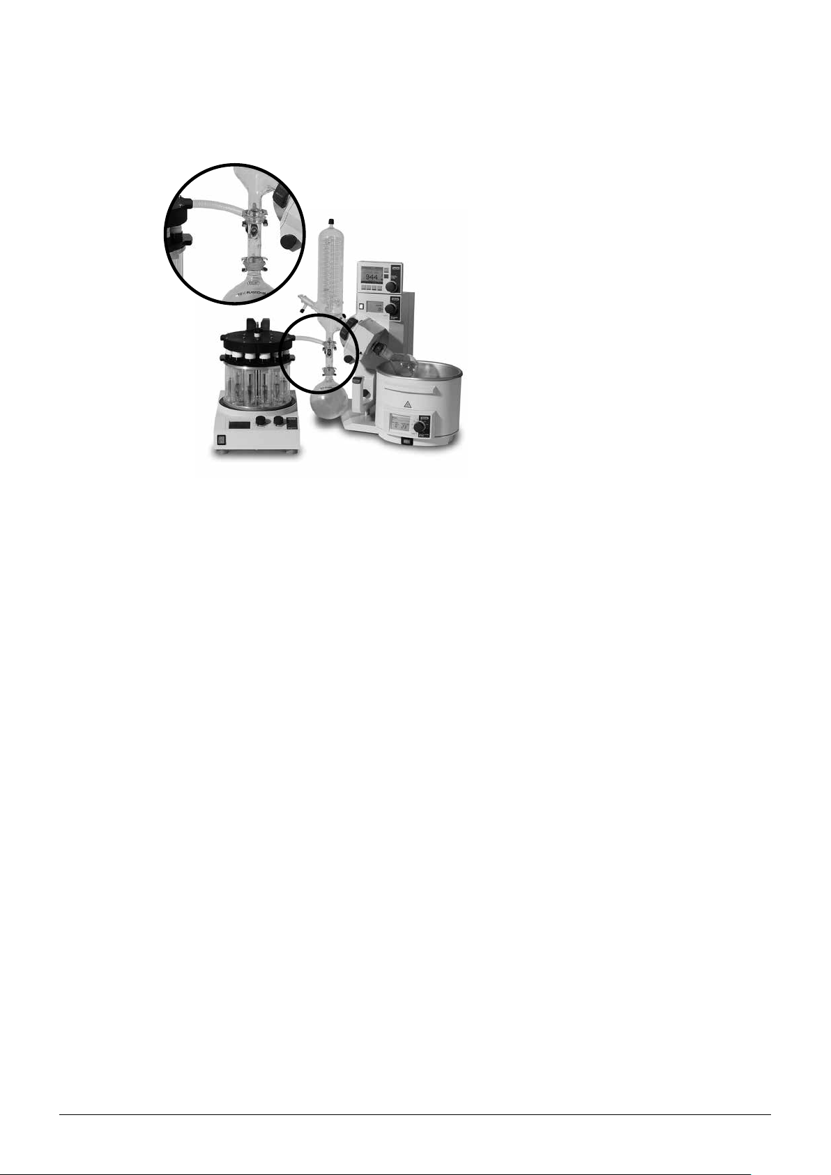
4.1.2 Functional principle of the Multivapor-Rotavapor edition
2
1
3
Fig. 4.3: Combination of the Multivapor P-6/P-12 with the Rotavapor R-215
The vacuum tube of the Multivapor is connected to the T-piece a which is installed between the
condenser and receiver of the Rotavapor. The key feature of this setup is that the condenser assembly
b, the vacuum pump c and the vacuum controller d are shared between both the Multivapor and
the Rotavapor. Therefore both single evaporation of large flasks and parallel evaporation of small test
tubes is achievable with the same setup using little space. However, simultaneous performance of
both tasks is neither feasible nor advisable due to physical reasons, as the cooling capacity of the
4
5
29 Multivapor™ Operation Manual, Version E
Page 30
condenser cannot cope with the amount of vapor produced. During operation of the Multivapor, the
Rotavapor side has to be closed using an empty evaporation flask e.
4.1.3 Controls of the Multivapor (stand-alone)
5
4 Description of function
a Main switch
b Temperature display
c Knob for temperature regulation
d Knob for rotational speed
e Holder for the vacuum cover
3
2
1
Fig. 4.4: Overview of the Multivapor controls
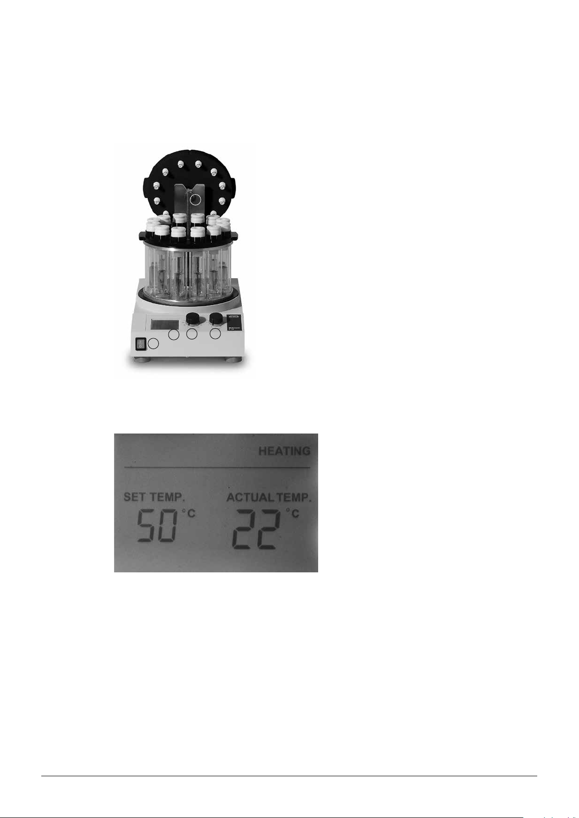
4.1.4 Display of the Multivapor
Fig. 4.5: Display of the Multivapor
4
The display shows both the actual and the set
temperatures. If the actual temperature is below
the set temperature, the indication “heating”
appears.
30 Multivapor™ Operation Manual, Version E
Page 31

4.1.5 Rear connections of the Multivapor
Fig. 4.6: Rear connection of the Multivapor
4.2 Multivapor platform
4 Description of function
a Mains supply
b Main fuse
2
1
The platform is available with a 220–240 V and a
100–120 V power supply. The temperature and
orbital movement of the heating plate are individually adjusted via the corresponding control
knobs. The temperature is limited to 95 °C to
prevent evaporation of water which is used as
heat transfer medium. Both the set and actual
temperature of the heating plate are shown in
the display.
The horizontal orbital speed of the heating plate
is indicated by a graduation (0…10) and ranges
from 0 to 370 rpm for the Multivapor P-6, or 0 to
485 rpm for the Multivapor P-12.
A black rubber gasket a prevents contamination of the instrument interior with liquids.
1
Fig. 4.7: Multivapor platform
31 Multivapor™ Operation Manual, Version E
Page 32

4.3 Crystal rack
4 Description of function
The crystal rack a is fixed onto the heating
plate and operates as a heat transition between
the heating plate and the sample tubes. It comprises 6 or 12 glass cylinders accommodated
circularly to provide full supervision. A level
indication designates the optimal filling level for
water, which serves as the heating medium.
A further advantage of the crystal rack compared to the widely used metal racks is the
compatibility with all kind of sample tubes differing in shape, diameter and length.
1
Fig. 4.8: Multivapor with the crystal rack
4.4 Sample preparation rack
1
4
Fig. 4.9: Sample preparation rack with the transfer plate and test tubes with the corresponding adapters
The sample preparation rack a serves as support for the transfer rack b including 6 or 12
sample tubes c.
The tubes are equipped with specific adapters
d which seal the test tubes effectively with the
3
2
vacuum cover.
32 Multivapor™ Operation Manual, Version E
Page 33

4.5 Blank adapters (optional)
Fig. 4.10: Blank adapters
4 Description of function
If less than the maximum number of samples are
being evaporated, the vacant positions need to
be occupied either with empty sample tubes or
with the optional blank adapters. These adapters consist of a closed bottom side but the
same outer dimensions as the standard adapters.
It is not necessary to distribute the samples
equally across the crystal rack. It is therefore
possible to accommodate the front positions
with the samples and the back positions with the
blank adapters.
For very harsh conditions, such as evaporation
of trifluoro acetic acid (TFA), the adapters are
also available in PEEK.
4.6 PE frits
Fig. 4.11: PE frits
4.7 Adapter spring
In order to reduce contamination of the vacuum
cover by foaming samples or boiling retardation,
an optional porous PE frit can be placed into
the tube adapters closing the vapor duct. This
measure also allows sample adsorption onto
silica for chromatographic purposes (dry loading)
by retaining the silica inside the tube.
Springs on the top of the tube adapters are
optionally used to facilitate the opening of the
vacuum cover.
Fig. 4.12: Adapter spring
33 Multivapor™ Operation Manual, Version E
Page 34

4.8 Sample transfer plate
Fig. 4.13: Simultaneous sample transfer using the transfer plate
4 Description of function
As the test tubes are tightly fixed to the transfer
plate, the whole assembly is transferred at once
into the crystal rack. This allows a preceding
equilibration of the instrument.
4.9 Vacuum cover
2
The samples are sealed with the vacuum cover
a via the adapters b. The cover serves as
vacuum manifold collecting the vapor from each
sample individually in grooved channels. This
reduces the chance of cross-contamination
1
significantly. A descending drain is connected to
the condenser assembly by means of a ribbed
PFA vacuum tube.
Fig. 4.14: Multivapor with the crystal rack and the corresponding vacuum cover
34 Multivapor™ Operation Manual, Version E
Page 35

4.10 Protective shield (optional)
4 Description of function
The protective shield protects the user from
splashes of hot medium and debris from the
sample tubes in the case of implosion or explosion.
Fig. 4.15: Protective shield
4.11 Condensation (optional)
Fig. 4.16: Type C (left) and type S (right) condenser assemblies
There are two types of condensers available.
Type C condensers (left) are used with dryice/acetone and type S condensers (right)
are connected to tap water or a recirculating
chiller. Both are equipped with a P+G coating
to provide maximum safety. The receiving flask
is available in 1 or 2 l capacity. Alternatively, an
insulated refrigerated receiver with an internal
cooling coil can be used in combination with
a type S condenser. This allows evaporation
of solvent mixtures with different boiling points
without interruption between fractions.
35 Multivapor™ Operation Manual, Version E
Page 36

4.12 High-boiling solvents - Woulff bottle (optional)
To prevent boiling retardation and for highboiling solvents which tend to condense in the
vacuum tube as well as for solvents which tend
to foam an optional solvent reservoir – the socalled Woulff bottle – can be fixed at the rear of
the instrument. The vapor is then first transferred
from the cover to the bottle and then further to
the condenser assembly.
Fig. 4.17: Woulff bottle installed
4 Description of function
4.13 Vacuum solution (optional)
Evaporation under vacuum is performed by
means of a vacuum pump. With the V-700 PTFE
diaphragm pump an ultimate vacuum of less
than 10 mbar is achieved, which is more than
sufficient for most applications.
Sophisticated vacuum control is gained using
the V-850 or V-855 controller. The latter includes
gradient functions, solvent libraries and automatic vacuum control algorithms.
Fig. 4.18: Recommended vacuum solution for use with the Multivapor
36 Multivapor™ Operation Manual, Version E
Page 37

4.14 Connection to a rotary evaporator (optional)
Fig. 4.19: A resource-sharing combination of the condenser, the vacuum pump and the controller with both the Rotavapor and the Multivapor
4 Description of function
In addition to the stand-alone unit, the Multivapor can be used in combination with a rotary evaporator.
The vapor is then first transferred to the condenser assembly of the Rotavapor with the help of the
T-piece. The vacuum is generated by the vacuum pump and regulated by the controller.
The glass T-piece used for this setup is compatible with all BUCHI products and the major manufacturers of rotary evaporators. The prerequisite for a compatibility is the presence of an S35 spherical
joint between the condenser and the receiving flask.
4.15 Refrigerated receiver (optional)
The refrigerated receiver keeps the solvent at a
low temperature throughout the run. It is essentially a horizontal cylindrical receiving flask with
an insulation jacket and an internal cooling loop.
The cooling loop is connected to a recirculating
chiller and keeps its content at a low temperature. A curved U-tube serves as a level indicator
and allows the flask to be emptied without disconnection. The total volume of the flask is 2.5 l.
Fig. 4.20: Cooled receiver with type S condenser
37 Multivapor™ Operation Manual, Version E
Page 38

5 Putting into operation
This chapter describes the installation of the Multivapor and gives instructions on initial start-up.
NOTE
Inspect the instrument for damages during unpacking. If necessary, prepare a status report immediately to inform the postal company, railway company or transport company. Keep the original
packaging for future transport.
5.1 Installation site
Place the instrument on a stable, horizontal surface and consider the maximum product dimensions.
NOTE
The shaking platform moves horizontally in an orbital manner with up to 485 rpm (for the P-12) which
may lead to considerable shaking of the surface. For this reason ensure that the surface is stable.
It is not necessary to place the instrument in a fume hood, however, the exhaust gas from the vacuum
pump should be directed toward a fume hood.
5 Putting into operation
5.2 Electrical connections
Risk of instrument damage by wrong mains supply.
• External mains supply must meet the voltage given on the type plate
• Check for sufficient grounding
NOTICE
38 Multivapor™ Operation Manual, Version E
Page 39

5.3 Commissioning the Multivapor basic instrument
5.3.1 Commissioning the crystal rack
5 Putting into operation
Fig. 5.21: Installation of the crystal rack onto the heating plate
Remove any particles from the heating plate and the bottom side of the crystal rack. Place the rack
onto the heating plate with the indentation to the front.
Put the rack back on the instrument - the three pins have to be aligned with the openings in the
bottom of the rack and the notches 1 on the rack have to point to the front side (a little left from the
middle) of the instrument.
Pull and hold the locking device 2.
Turn the rack a little counter clockwise and let the locking device go 3.
Turn the rack further counter clockwise, until the locking device snaps into place.
Optionally you can fix the the rack with the supplied four screws 2.
Check the rack for a tight mounting!
39 Multivapor™ Operation Manual, Version E
Page 40
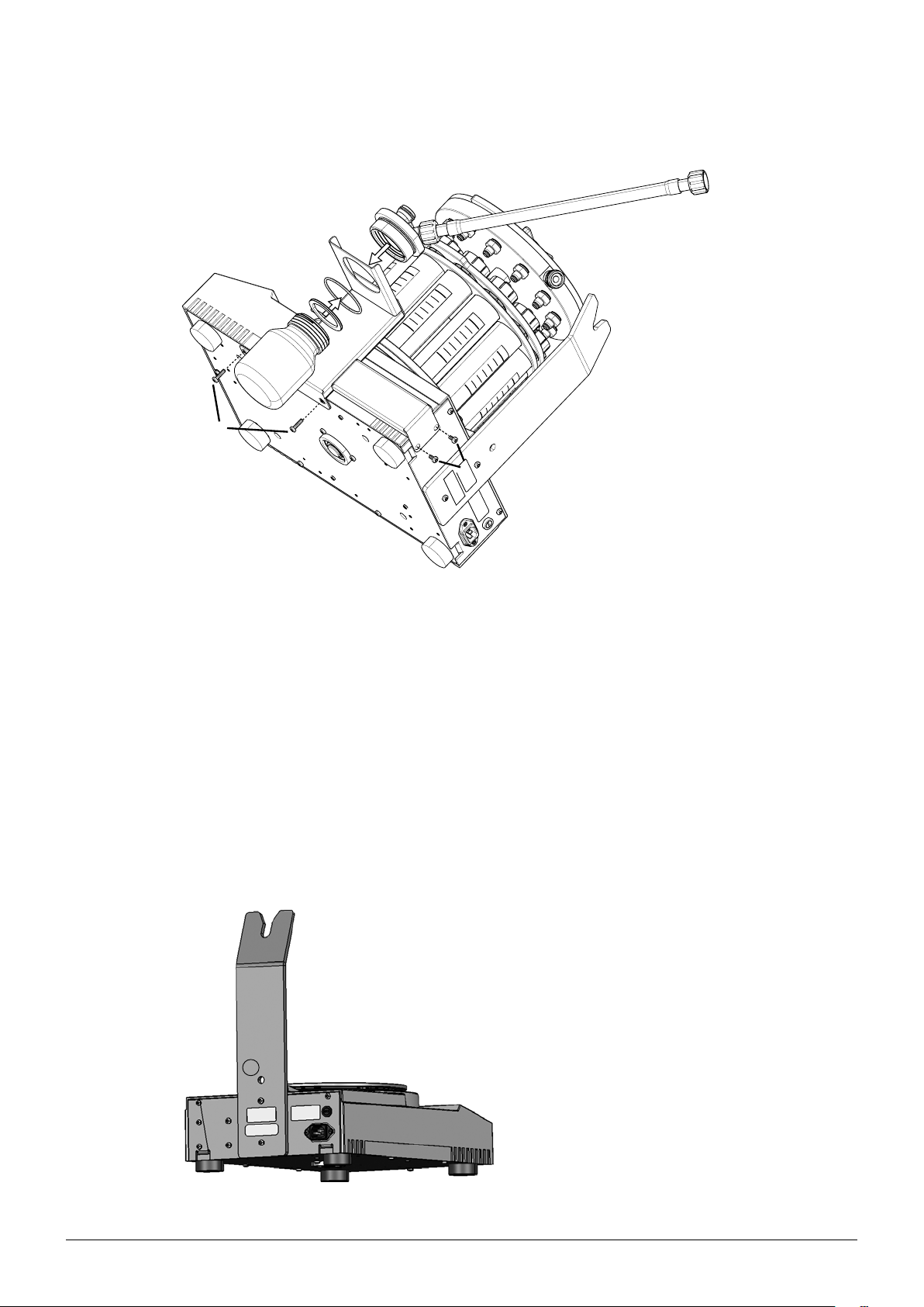
5.3.2 Assembling the Woulff bottle (optional)
5 Putting into operation
Fig. 5.22: Assembling the Woulff bottle
1
Fix the Woulff bottle holder on the bottom of the instrument by replacing the existing screws with the provided
longer screws.
2
Fix the Woulff bottle holder on the rear side of the instrument by replacing the existing screws with the provided longer screws.
Add the cover of the Woulff bottle from above to the holder.
Fix the cover from below on the holder with the provided O-ring.
Place the gasket from below into the cover.
Screw the bottle into the holder.
Connect the delivered tube on the left angled connector of the cover.
Connect the tube from the condenser to the Woulff bottle on the right straight connector (not connected in the
figure).
5.3.3 Anti-seismic tie-down
a Hole to fix the instrument in earthquake-sus-
ceptible regions.
1
Fig. 5.23: Anti-seismic tie-down
40 Multivapor™ Operation Manual, Version E
Page 41

5.4 Glass assembly
5 Putting into operation
Risk of glass breakage by excessive strains.
• Mount all glassware parts without strains
• Check glassware for proper fixing regularly and readjust fixing points if necessary
• Do not use defective glassware
• Use the protective shield (optional)
5.4.1 Type S and type C condenser
1
NOTICE
Install the condenser assemblies on the provided support or on a stable laboratory rod
ensuring that the stand base is oriented in the
direction of the condenser.
Secure the receiving flask with the clip a provided for this purpose.
1
Fig. 5.24: Installation of the condenser assembly on the support
5.4.2 Condenser assembly with the refrigerated receiver (optional)
The refrigerated receiver a can be used as an
alternative to the receiving flask and is secured
using the clip b. The internal cooling loop is
connected to a cooling source c (tap water or
recirculating chiller).
2
1
Fig. 5.25: Type S condenser with the refrigerated receiver
3
41 Multivapor™ Operation Manual, Version E
Page 42

5.5 Tube connections
5.5.1 Cooling water
When connecting the white cooling water tubes (silicon), consider the following:
• Use GL-14 tube clips.
• The tubes used must all have the same inner diameter (approximately 6 mm).
• For safety reasons, secure the tubes with commercial tube pivoting clamps or cable binders.
• To save cooling water and/or reduce the temperature of the coolant, a recirculating chiller like the
F-100/F-108 is recommended.
• Check the tubes from time to time and replace them if they become brittle.
5 Putting into operation
4
2
3
5 1
a Coolant in
b Secondary condenser (optional)
c Refrigerated receiver (optional)
Fig. 5.26: Liquid flow direction for primary condenser and post-pump secondary condenser
d Primary condenser
e Coolant out
NOTE
It is important to connect the coolant with the secondary condenser first and then with the primary
condenser as the temperature rise in the coolant primarily takes place in the latter.
When the type C condenser is used no tube connections for cooling are required.
42 Multivapor™ Operation Manual, Version E
Page 43

5.5.2 Vacuum tubes
When establishing the vacuum tube (red rubber) connections proceed as follows:
• Use GL-14 tube clips.
• The tubes used must all have the same inner diameter (approximately 5 mm).
• Keep vacuum tubes as short as possible.
• When operating with the Vacuum Controller V-850/V-855 and the Vacuum Pump V-700/V-710
connect a Woulff bottle between the vacuum source and the Multivapor.
• When operating with a pump other than a V-700/V-710, connect a valve unit to the V-850/V-855 to
control the vacuum.
• Tubes do not need to be secured.
• Check the tubes from time to time and replace them if they become brittle.
5 Putting into operation
6
5
1
2
a Vacuum cover out
b Woulff bottle at Multivapor (optional)
c Condenser vacuum joint
Fig. 5.27: Standard vacuum connections with condenser and V-700/V-855 vacuum solution
3
4
d Woulff bottle at vacuum pump (optional)
e Woulff bottle connection to vacuum pump
f Woulff bottle connection to vacuum controller
4
43 Multivapor™ Operation Manual, Version E
Page 44
5.6 Commissioning the Multivapor-Rotavapor edition
The T-piece is inserted between the condenser
and the receiving flask of the rotary evaporator
and fixed with the clip. The vacuum tube is connected to the SVL 22 joint of the T-piece.
5 Putting into operation
Fig. 5.28: Commissioning the Multivapor-Rotavapor edition
NOTE
As the system has to be closed in order to generate a vacuum, the vapor duct on the rotary evaporator must be sealed with an empty flask during operation.
5.7 Functional test
Once all of described installation steps have been completed proceed with the following functional test
to correctly operate the instrument.
5.7.1 Vacuum tightness test
NOTE
The vacuum tightness test can only be carried out with a vacuum controller installed or when a pressure measuring device (manometer) is installed between the pump and the Multivapor.
1. Start the instrument and adjust the desired rotational speed, e.g. position 8.
2. Apply a vacuum of a preset value, e.g. 100 mbar.
3. Stop the vacuum and measure the pressure increase ∆p within 2 min.
4. The instrument is tight if ∆p < 10 mbar within 2 min.
To tighten the instrument, proceed as follows:
1. Close the vacuum tube from the vacuum pump to the condenser and check the leak rate of the
pump. In case of a leak consult the operation manual of the vacuum pump.
2. Close the vacuum tube at the vacuum tube side of the condenser with a blind cap and check the
leak rate of the condenser assembly. In case of a leak check the seals of the vacuum tube and the
GL-14 caps. Grease the glass joints if necessary.
3. Close the conical adapters of the vacuum cover using the blank adapters. In case of a leak
exchange the seals of the ribbed vacuum tube and/or the O-rings at the conical adapters. In case
of chemically affected O-rings, change the material of the O-rings according to Table 3-5.
4. Verify the quality of the sample tubes. They must not be chipped.
5. Check if the seals for the tube adapters are sound and correctly placed. In case of a leak exchange
44 Multivapor™ Operation Manual, Version E
Page 45

5 Putting into operation
the corresponding seals. The adapter seals have to be exchanged regularly. The corresponding
spare parts are listed in section 10.3.
NOTE
Overtightening the lock nuts on the conical adapters of the vacuum cover and sample tubes will
scarcely remedy a leak problem, but would decrease the lifetime of the parts. The problem is more
readily solved by checking the quality of the corresponding seals, i.e. the adapter seals and/or the
conical O-rings.
Risk of thread damage by overtightening
• Do not use a wrench with a long lever arm when exchanging the conical adapters due to
Fig. 5.29: Tightening the lock nuts on the conical adapters
NOTICE
physical or chemical damage
45 Multivapor™ Operation Manual, Version E
Page 46

6 Operation
This chapter explains the operating elements and possible operating modes. It gives instructions on
how to operate the Multivapor properly and safely.
6.1 Settings at the Multivapor platform
Variable parameters of the instrument are the temperature and rotational speed of the horizontal
movement of the heating plate.
6 Operation
Risk of glass breakage by excessive strains.
• Mount all glassware parts without strains.
• Check glassware for proper fixing regularly and readjust fixing points if necessary
• Do not use defective glassware.
• Use the protective shield (optional).
Risk of instrument damage by lack of heating medium in the crystal rack.
• Make sure that there is always heating medium within the crystal rack when the instrument is
Risk of minor or moderate burns when handling hot parts.
• Do not touch hot parts or surfaces (especially the heating plate with up to 95 °C).
• Make sure that no liquid can overflow from the glass cylinders when the samples tubes are
• Use the protective shield (optional) to shield hot parts.
NOTICE
NOTICE
switched on and the actual temperature is below the set temperature.
CAUTION
!
submerged.
NOTE
The display specifies the temperature of the water in the glass cylinder. During evaporation heat is
transferred from the heating medium to the condenser eventually, which may result in a considerable temperature drop of up to 15 °C in the water bath. This fact has to be taken into account when
selecting an appropriate coolant temperature inside the condenser.
46 Multivapor™ Operation Manual, Version E
Page 47

6.1.1 Selecting a preset temperature
A preset temperature setting ensures that the heating bath temperature cannot be changed either
accidentally or deliberately during the evaporation process.
To switch to the preset mode, proceed as follows:
• Switch off the instrument.
• Turn the adjusting knob to the 95 °C (max) position.
• Switch on the instrument. The set temperature setting flashes on the display.
• Turn the knob to the desired set temperature, e.g. 60 °C within 10 seconds and wait until the set
temperature setting stops flashing.
• This set temperature is now retained whenever the heating bath is switched on and cannot be
changed with the adjusting knob anymore.
6.1.2 Changing/switching off the preset temperature
To change or switch off the preset temperature, proceed as follows:
• Switch off the instrument.
• Turn the adjusting knob to the 0 °C (min) position.
• Switch on the instrument. The preset temperature setting is now deleted and the temperature can
be selected via the knob again.
6 Operation
6.1.3 Setting the rotational speed
!
Risk of minor or moderate injuries due to wrong rotation speed adjustment!
• Do not exceed 370 rpm if using the P-12 platform with the P-6 configuration. Otherwise
strong vibration will damage the P-12 and glass cylinders.
NOTE
As soon as the power plug is connected and the main switch is turned on, the platform moves horizontally in an orbital manner according to the setting adjusted at the corresponding knob.
The rotational speed of the moving platform ranges from 0 to 370 rpm for the Multivapor P-6 and from
0 to 485 rpm for the Multivapor P-12. Within this range even fairly viscous samples are thoroughly
agitated by strong vortex action. For most applications a constant rotational speed at position 8 is
sufficient.
The absolute value of the rotational speed is not displayed. The indication 0…10 on the platform
is linearly increasing from 0 corresponding to 0 rpm to 10 corresponding to 370 rpm or 485 rpm,
respectively.
NOTE
Once optimized, the vortex action remains constant throughout the evaporation process, given that
the shape and inner diameter of the sample tubes is constant. Changing glassware geometries, e.g.
to conical bottoms (the so-called Falcon tubes) or rounded tubes, may alter the efficiency of agitation which may result in boiling retardation. It is therefore advisable to adjust the rotational speed
during the process.
CAUTION
47 Multivapor™ Operation Manual, Version E
Page 48

6.2 Sample preparation
6.2.1 Heating up the instrument
Fig. 6.30: Filling distilled water to a level where strong agitation during operation is obtained
6 Operation
Distilled water is added to each glass cylinder
on the crystal rack to transfer the heat from the
heating plate to the sample tube. Equal amounts
of water must be added to each cylinder to
provide a uniform heat transfer. A level indication
designates the optimum volumes depending on
the type of sample tube.
Turn on the heating as soon as each position
is filled. It takes approximately 20 min to equilibrate the system, i.e. until the water temperature
remains constant.
NOTE
• The water volume is the decisive parameter for optimal heat transfer, therefore it is not advisable
to add too much water. Heat transferred into the sample decreases with an increasing volume.
This is mainly the result of insufficient mixing of the heating medium. Therefore, fill in only as much
water so that the sample vessel dips into the heating medium by 2 to 3 cm. Optimize the rotation
to obtain a vigorous vortex for both the sample and the heating medium.
• To reach equilibrium turn on the instrument and set it to the desired evaporation temperature
20 min prior to the distillation process.
6.2.2 Sample preparation
The installation and sealing of the sample tube is carried out as follows:
Risk of lifetime shortening of the adapter seals and the quick lock nut.
• Fix all connections only hand tight.
• Avoid overtightening.
NOTICE
• Use the Multivapor tool for removing the
insert of the adapter and for changing the
gasket.
48 Multivapor™ Operation Manual, Version E
• Use the optional PE frits for foam and splash
protection.
• To remove the optional PE frits from the tube
adapter, push a thin object from the top
through the hole.
Page 49

6 Operation
• Screw the adapter onto the tube. • Place the sample tube into the transfer plate.
Make sure that it snaps in place.
• Occupy all positions or use the blank
adapters instead (optional).
• Transfer the whole assembly at once into the
pre-heated crystal-rack.
• Close the vacuum cover. • Tighten the vacuum cover using the quick
lock.
Fig. 6.31: Sample preparation
49 Multivapor™ Operation Manual, Version E
Page 50

6.3 Selecting the distillation conditions
To achieve optimal distillation conditions, the distillation energy supplied by the heating platform must
be removed by the condenser. To ensure this, operate the instrument according to the following
general rule:
Heating medium: 55 °C
How are these conditions achieved?
• Set the temperature of the instrument to 55 °C.
• Use a recirculating chiller to set the temperature of the coolant to max. 10 °C or use a dry-ice
condenser (type C) alternatively.
• The coolant flow is adjusted to approx. 600 – 800 mL/min.
• Define the operating vacuum according to the boiling point of the solvent which in this particular
example is 30 °C. The corresponding pressure can be deduced from the enclosed Solvent Table or
from the Solvent Library implemented in the Vacuum Controller V-850/V-855.
25 °C
Vapor: 30 °C
6 Operation
20 °C
Coolant: max. 10 °C
This rule can be extrapolated to higher temperatures, e.g. according to the following example:
Heating plate: 75 °C
Δ T ≥ 20 °C
Δ T ≥ 25 °C
25 °C
Vapor: 50 °C
20 °C
Coolant: max. 30 °C
Fig. 6.32: Schematic depiction of the relative temperature drop within the distillation setup
NOTE
The 25/20 °C rule indicates that during operation the displayed temperature does not correspond to
the temperature of either the vapor or the sample mixture. During distillation there is a temperature
drop relative to the display of approx. 10 °C for the sample and approx. 25 °C for the vapor.
The distillation conditions of the Multivapor are therefore not directly comparable to that of the
Rotavapor as the heat transfer in the latter, from heating bath to sample flask, is more efficient
compared to that observed in the Multivapor. At identical set temperatures, the actual temperature
of the Multivapor sample would be approx. 15 °C less than the Rotavapor sample.
50 Multivapor™ Operation Manual, Version E
Page 51

6.4 Distillation
Before operating the system, the following conditions must be fulfilled:
• All electrical connections are established correctly.
• All vacuum and coolant connections are established correctly. The latter being secured with cable
binders.
• All seals are inserted correctly.
• Water is filled in according to the level indication.
To start operating the system proceed as follows:
• Switch on the instrument.
• Set the temperature (recommended: 50 – 80 °C).
• Adjust the coolant flow (recommended: 5 – 20 °C, 600 – 800 mL/min).
• As soon as the instrument is equilibrated (after approx. 20 min), place the sample tubes into the
crystal rack. Use empty sample tubes or blank adapters (optional) to occupy vacant positions.
• Close the vacuum cover and screw it hand tight.
• Set the rotational speed (recommended: pos. 8 - 10).
• Turn on the vacuum pump and controller.
• Set the vacuum according to the 25/20 °C rule.
• Wait approx. 5 min after the vacuum has reached the set point. The temperature of the sample
may, depending on the set temperature, drop during initial evaporation, resulting in a slight subsequent readjustment of the vacuum conditions.
• If the distillation does not start, carefully reduce the vacuum gradually or increase the temperature at the instrument. Check the efficiency of the condenser and make sure that the vapor is not
directly sucked into the pump.
6 Operation
NOTE
In general the smaller the test tubes the higher the risk of boiling retardation. In order to prevent
contamination of the vacuum cover apply a pressure gradient to reduce the pressure gradually (see
chapter 6.5.2) and/or use the optional PE frits as splash and foam protection.
6.5 Optimizing the vacuum conditions (optional)
There are three distinct ways to evaporate multiple samples in parallel with the Multivapor using
either the Vacuum Controller V-850 or V-855. The main functions are described briefly in the following
sections. For further information please consult the corresponding Operation Manual.
6.5.1 Manual vacuum control and solvent library (V-850/V-855)
Choose the temperature according to the 25/20 °C rule. The corresponding pressure is best derived
from the Solvent Library. This is achieved as follows:
• Open the Solvent Library. • Select the corresponding
solvent.
51 Multivapor™ Operation Manual, Version E
• Set the instrument temperature.
Page 52

6.5.2 Pressure gradients (V-855)
Setting the pressure manually to the boiling point involves the risk of boiling retardation. To minimize
this risk, it is strongly recommended to program a pressure gradient that slowly converges to the optimized ultimate vacuum. This is achieved as follows:
• Select the Gradient mode. • Program the first step. • Program additional steps and
6 Operation
terminate the programming
by selecting “Yes”.
The corresponding gradient can be stored for future recall and displayed at any time. For further
information please consult the operation manual
of the vacuum controller.
Fig. 6.33: Pressure gradient for distillation of ethanol at 65 °C (instrument setting)
It is often desirable to dry any remaining solid
sample immediately after solvent evaporation.
For routine procedures it is advisable to implement this step directly into the gradient program.
This reduces the amount of instrument handling
and keeps supervision to a minimum.
Fig. 6.34: Example of a gradient setting with a drying step subsequent to the solvent evaporation
NOTE
A direct drying step without interruption of the distillation process is only possible if the distilled
solvent is kept at low temperature, i.e. below the corresponding boiling point of the ultimate vacuum
setting. This is achieved by using an ice bath or the optional refrigerated receiver in combination with
a recirculating chiller.
Pressure gradients are also an ideal tool for complex mixtures with low-boiling components which
52 Multivapor™ Operation Manual, Version E
Page 53

tend to foam or splash. A preceding terrace at high pressure for approx. 10 min usually significantly
reduces the risk of splashing or foaming.
6.5.3 Automatic distillation (V-855)
1
6 Operation
The method of choice to evaporate even complex
sample mixtures automatically is the EasyVac mode,
implemented in the Vacuum Controller V-855. The
EasyVac algorithm is based on relative pressure
changes over time and therefore requires no additional
accessory for operation.
It is possible to interrupt the algorithm at any time by
pressing the P↑ button b and resuming the automatic
process by pressing the H Off button a. This is a very
helpful measure to reduce foaming and splashing for
2
delicate mixtures.
Fig. 6.35: Automatic distillation
NOTE
A tight system, i.e. ∆ p < 5 mbar per minute, is an essential prerequisite for the proper operation of
EasyVac.
6.6 Optimizing the distillation conditions
Depending on the distilled solvent optimization of the parameters during the process is sometimes
required. An optimal loading of the condenser is approx. ½ of its height.
To achieve this either
• reduce the pressure or
• increase the temperature
½
Fig. 6.36: Optimal loading of the condenser
NOTE
In case of a temperature rise only a fraction of the additional energy is used for distillation. The
majority is discharged into the environment due to the increasing temperature difference of the
53 Multivapor™ Operation Manual, Version E
Page 54

heating plate and the ambient temperature.
6.7 When the distillation “dies out”
When the distillation “dies out”, i.e. the process draws to a close, back evaporation may occur. In this
event appropriate actions are either to interrupt the distillation in order to empty the receiving flask or
to keep the solvent at a low temperature (see also section 6.5.2).
A convenient accessory for the latter is the refrigerated receiver.
The solvent can be disposed of by opening the top GL-14 tube connection and subsequently draining
the solvent into a beaker.
6 Operation
Fig. 6.37: Drainage of the cooled receiving flask
6.8 At the end of a run
Fig. 6.38: Holder for the vacuum cover
When the distillation is complete the system is aerated and the
rotation is stopped.
By the time the quick lock nut is opened, the retaining springs
(not shown in the picture) pull the vacuum cover and the tube
adapters apart, facilitating the opening of the cover. However,
the instrument can also be operated without the retaining
springs.
Put the vacuum cover to its holder and transfer the samples
back to the sample preparation rack. Thus, the time during
which the samples are exposed to a warm environment is
reduced.
If there is no intention to perform another distillation, turn off
the instrument and the coolant supply to save energy and
resources.
54 Multivapor™ Operation Manual, Version E
Page 55

7 Maintenance
This chapter provides instructions on all required maintenance to keep the instrument in good working
condition.
7.1 Housing
WARNING
!
Death or serious burns by electric current at cleaning.
• Switch off the instrument
• Disconnect the power cord and prevent unintentional restart
• Wait until the instrument is completely dry before reconnecting to mains
7 Maintenance
Risk of instrument damage by using solvents as cleaning agents.
• Use a moist cloth and mild soap to clean the instrument.
Check the housing for defects (controls, plugs) and clean it regularly with a moist cloth.
NOTICE
7.2 Tube connections and joints
Visually examine the tube connections regularly, if tubes become cracked and brittle replace them with
new ones.
Grease all joints at the condenser side regularly to achieve an optimum sealing of the system.
7.3 Sealing system
Risk of seal damage by improper handling.
• Never apply grease.
• Never touch the seals with sharp objects.
NOTICE
Clean the seals regularly and visually examine them at this occasion. If seals become cracked and
brittle replace them with new ones.
7.3.1 Cleaning the seals
To prolong the lifetime of the seals, rinse them routinely with water or ethanol and always in case of
unwanted sample contamination (foaming or boiling retardation). Dry the cleaned seals with a soft
cloth.
55 Multivapor™ Operation Manual, Version E
Page 56

7.3.2 Replacing the tube adapter seals
1 2
Fig. 7.39: Replacing the tube adapter seals
7.3.3 Replacing the conical adapter O-rings
7 Maintenance
a Use the Multivapor tool for removing the insert
of the adapter and for changing the gasket.
b Replace the gasket if damaged or broken,
and reassemble.
Fig. 7.40: Replacing the conical adapter O-rings
The O-ring of the conical adapters may become either chemically or physically damaged under harsh
conditions or upon intensive regular use respectively.
The vacuum cover is equipped with EPDM O-rings. A set of 12 FKM O-rings is enclosed. A list of
recommended applications and restrictions depending on the material is given in Table 3-8.
Alternatively, for very harsh conditions FFKM O-rings are availble (see also chapter 10.2), which are
provided on the PEEK vacuum cover.
In order to remove the O-rings push with one hand horizontally and with the other vertically to the top.
56 Multivapor™ Operation Manual, Version E
Page 57

7.3.4 Cleaning the vacuum cover and replacing the corresponding O-rings
7 Maintenance
Fig. 7.41: Cleaning the vacuum cover
7.4 Crystal rack
Risk of component damage.
• Close the screws at the vacuum cover hand-tight.
• Avoid overtightening.
NOTICE
Clean the vacuum cover regularly by rinsing it
with water or ethanol through the holes of the
conical adapters.
Unmount the cover only in case of severe contamination. Use the optional PE frits to protect
the cover from any possible splashes (see also
chapter 4.6).
Fig. 7.42: Removing the crystal rack for cleaning
57 Multivapor™ Operation Manual, Version E
Page 58

7 Maintenance
To remove the crystal rack for cleaning, proceed as follows:
1
Pull and hold the locking device.
2
Turn the rack a little clockwise and let the locking device go.
Turn the rack further clockwise, until the lockingdevice snaps into place.
The rack can now be taken away from the instrument.
To reinstall the rack proceed in reverse order:
Put the rack back on the instrument - the three pins have to be aligned with the openings in the
bottom of the rack and the notches on the rack have to point to the front side (a little left from the
middle) of the instrument.
Pull and hold the locking device.
Turn the rack a little counter clockwise and let the locking device go.
Turn the rack further counter clockwise, until the locking device snaps into place.
Check the rack for a tight mounting!
To clean the crystal rack remove it from the platform and drain it with water.
In case of glass breakage or severe contamination, disassemble the crystal rack as follows:
• If the rack is screwed to
the platform, remove the
four screws at the bottom.
Remove the rack and empty
it.
1
1
Fig. 7.43: Reassembling the crystal rack
• If necessary, unscrew the top
screw nuts and remove the
lid.
In most cases the removal and cleaning of the whole
assembly is sufficient, only disassemble the rack in the
event of glass breakage or severe contamination.
To reassemble the crystal rack, place the flat seal into
the grooved rings of both the rack base and the lid.
Place the glass cylinders onto the seals and close them
with the lid according to Fig. 7.43. Make sure that the
indentation a of the bottom and top plate is oriented in
one line.
• Disassemble the whole rack.
58 Multivapor™ Operation Manual, Version E
Page 59

NOTE
Screw the lid only hand-tight as overtightening may break the glass cylinders. Test the tightness of
the system with water prior to the installation onto the heating plate.
7.5 Glass components
To prolong the lifetime of the glass components rinse them regularly with water and a commercial
cleaning agent (e.g. mild soap solution).
NOTE
It is recommended to clean all glass components manually. Use an alkaline cleaner to remove dirt,
e.g. algae adhering to the condenser coil.
When a thin copper wire is introduced into the condenser coil, the risk of dirt adhering to the
condenser coil is reduced.
Remove all grease from the joints. After cleaning and completely drying each glassware component,
visually inspect them for glass splinters or tears. As these components are under vacuum during
operation they are subject to strain.
Regularly check the glassware components for damage and use only glassware in perfect condition,
i.e. glassware without cracks or stars.
Chipped sample tube borders may cause leaking. Check the quality of the sample tubes regularly,
especially when a dishwasher is used.
7 Maintenance
7.6 PE frits (optional)
Fig. 7.44: Removing the PE frits
To remove the optional PE frits from the tube adapter, push
a thin object from the top through the hole.
59 Multivapor™ Operation Manual, Version E
Page 60

8 Troubleshooting
The following chapter describes how to resume operation of the instrument in the event of any minor
problem. It will list some possible occurrences, their probable cause and suggests how to remedy the
problem. The troubleshooting table below lists possible malfunctions and errors of the instrument and
describes operator enabled courses of action to correct some of those problems by him or herself.
The appropriate course of action is listed in the column “Corrective measure”.
The elimination of more complicated malfunctions or errors is usually performed by a BUCHI technical
engineer who has access to the official service manuals. In this case, please refer to your local BUCHI
customer service agent.
8.1 Malfunctions and their remedy
Table 8-1: General malfunctions and their remedy
Malfunction Possible cause Remedy
Instrument does not work Main switch off Switch on main switch
Instrument does not heat Over-temperature protection was
Temperature is not adjustable Instrument is set to the preset
Rotation is not smooth Uneven and/or unstable surface or 6
System leaks See chapter 5.7.1 See chapter 5.7.1
Vacuum is not reached System leaks See chapter 5.7.1
Distillation “died out” Solvent mixtures; initial overheating
8 Troubleshooting
Instrument is not connected to mains
supply
Fuse defective Replace the fuse. If this malfunction
burned
Fuse defective Replace the fuse. If this malfunction
temperature mode
position rack on a P-12 instrument
Back evaporation from the distillate Empty the receiving flask or cool the
Vacuum pump is inefficient Check the characteristics and
of the sample
Check mains connection
occurs again, contact the BUCHI
customer service.
Heating plate must be replaced.
Contact the BUCHI customer service.
occurs again, contact the BUCHI
customer service.
Follow the instructions in chapter
6.1.1
Adjust the height of the feet and/
or change location. Do not use a 6
position rack with a P-12 instrument
(see label on the front panel) with
rotations higher than 8. Place the
rack on a P-6 platform.
distillate (e.g. with an ice bath or the
refrigerated receiver)
leaking rate of the vacuum pump
Decrease the pressure until the
distillation starts again or increase
the temperature
60 Multivapor™ Operation Manual, Version E
Page 61

8 Troubleshooting
Table 8-1: General malfunctions and their remedy
Malfunction Possible cause Remedy
Distillation stopped despite not being
dried out completely
Back evaporation of the distillate
(especially for solvent mixtures)
Malfunction in distillation procedure
which is not exactly defined (e.g.
Empty the receiving flask and restart
the distillation or cool the distillate
Decrease the pressure manually until
the distillation starts again
sudden cooling, heat flow too low,
etc.)
Table 8-2: Malfunctions with vacuum controller and vacuum pump and their remedy
Malfunction Possible cause Remedy
Frequent switching of valve or pump System leaks See chapter 5.7.1
Vapor sucked into the pump Increase the pressure according to
the procedure described in chapter
6.6
Chosen hysteresis is too small Choose larger hysteresis (if end
vacuum is higher than 700 mbar
switch to automatic hysteresis)
Valve does not switch Valve is dirty or the valve cable is
disconnected
Check the cable connection. If this
malfunction occurs again, contact
the BUCHI customer service
Table 8-3: Error messages
Error number Possible cause Remedy
E01 Temperature sensor defective Contact the BUCHI customer service
E02 Triac defective, excess temperature Contact the BUCHI customer service
E70 Program error due to a software or an elec-
tronical error
8.2 Customer service
Only authorised service personnel are allowed to perform repair work on the instrument. These
persons have comprehensive technical training and knowledge of possible dangers which might arise
from the instrument.
Contacts for official BUCHI customer service offices are given on the BUCHI website at:
www.buchi.com. If malfunctions occur on your instrument or you have technical questions or application problems, please contact one of these offices.
The customer service offers the following:
• Spare part delivery
• Repairs
• Technical advice
Switch the instrument off and on again. If this
error still occurs, contact the BUCHI customer
service.
61 Multivapor™ Operation Manual, Version E
Page 62

9 Shutdown, storage, transport and disposal
9 Shutdown, storage, transport and disposal
This chapter instructs on how to shut down the instrument, how to pack it for storage or transport and
specifies the storage and shipping conditions.
9.1 Storage and transport
Store the instrument at a dry place. Store and transport the instrument in its original packaging.
!
WARNING
Death or serious poisoning by contact or incorporation of harmful substances.
• Wear safety goggles
• Wear safety gloves
• Wear a laboratory coat
• Flush the instrument and clean all accessories thoroughly to remove possibly dangerous
substances
• Do not clean dusty parts with compressed air
• Store the instrument and its accessories at a dry place in its original packaging
9.2 Disposal
To dispose of the instrument in an environmentally friendly manner a list of materials is given in
chapter 3, please ensure that the components are separated and recycled correctly. Please follow
current regional and local laws concerning disposal.
NOTE
When returning the instrument to the manufacturer for repair work, please copy and complete the
health and safety clearance form on the following page and enclose it with the instrument.
62 Multivapor™ Operation Manual, Version E
Page 63

9.3 Health and safety clearance form
Declaration concerning safety, potential hazards and safe disposal of waste, e.g. used oil.
Safety and health of our staff, laws and regulations regarding the handling of dangerous goods, occupational health and safety
regulations, safety at work laws and regulations regarding safe disposal of waste, e.g. waste oil, require that for all Rotavapors
and other products this form must be send to our office duly completed and signed before any equipment is repaired or
dispatched to our premises.
Products will not be accepted for any procedure and handling and repair / DKD calibration will not start before we
have received this declaration.
a) Fax or post a completed copy of this form to us in advance. The declaration must arrive before the equipment. Enclose
a second, completed copy with the product. If the product is contaminated you must notify the carrier (GGVE, GGVS,
RID, ADR).
b) Inevitably, the repair process will be delayed considerably, if this information is missing or this procedure is not obeyed. We
hope for your understanding for these measures which are beyond our control and that you will assist us in expediting the
repair procedure.
c) Make sure that you know all about the substances which have been in contact with the equipment and that all
questions have been answered correctly and in detail.
9 Shutdown, storage, transport and disposal
1. Product (Model): ..........................................
2. Serial No.: .....................................................
3. List of substances in contact with the
equipment or reaction products:
3.1 Chemical/substance name, chemical
symbol:
a) .........................................................................
b) .........................................................................
c) .........................................................................
d) .........................................................................
3.2 Important information and precautions,
e.g. danger classification
a) .........................................................................
b) .........................................................................
c) .........................................................................
d) .........................................................................
5. Way of transport / carrier:
.............................................................................
Day of dispatch to BÜCHI Labortechnik AG:
.............................................................................
We declare that the following measures where applicable - have been taken:
- The oil has been drained from the product.
Important: Dispose of according to national
regulations.
- The interior of the product has been cleaned.
- All inlet and outlet ports of the product have been sealed.
- The product has been properly packed, if necessary, please
order an original packaging (costs will be charged) and
marked as appropriate.
- The carrier has been informed about the hazardous nature of
goods (if applicable).
Signature: ...............................................................................
Name (print): ...........................................................................
Job title (print): ........................................................................
4. Declaration (please mark as applicable):
¤ 4.1 for non dangerous goods:
We assure for the returned product that
- neither toxic, corrosive, bilogically active, explosive, radioactive nor contamination dangerous in any way has occurred.
- the product is free of dangerous substances.
The oil or residues of pumped media have been drained.
Company’s seal: .....................................................................
Date: .......................................................................................
¤ 4.2 for dangerous goods:
We assure for the returned product that
- all substances, toxic, corrosive, biologically active, explosive,
radioactive or dangerous in any way which have pumped or
been in contact with the product are listed in 3.1, that the
information is complete and that we have not withheld any
information.
- the product, in accordance with regulations, has been
¤ cleaned
¤ decontaminated
¤ sterilized
63 Multivapor™ Operation Manual, Version E
Page 64

10 Spare parts
This chapter lists spare parts, accessories, and optional extras, including all of the relevant order
information for ordering from BUCHI. Always state the product designation and part number when
ordering any spare parts.
Use only genuine BUCHI consumables and spare parts for maintenance and repair to ensure optimum
system performance and reliability. Prior written permission of the manufacturer should be obtained
before any modifications are made to the spare parts used.
10.1 Basic instrument
10 Spare parts
Fig. 10.45: Multivapor platform
Table 10-1: Multivapor platform
Product Order number Product Order number
Multivapor cover ring 48789 Set of main fuses, T 3.1 A L 250 V
(for 220–240 V instrument) (10 pieces)
Set of 4 instrument feet 41984 Set of main fuses, T 6.3 A L 250 V
(for 100–120 V instrument) (10 pieces)
64 Multivapor™ Operation Manual, Version E
19659
22561
Page 65

10.2 Evaporation unit
11057259
10 Spare parts
Table 10-2: Evaporation unit P-6
Product Order number
Quick lock nut 11057259
Vacuum cover O-ring, small (EPDM) 49792
Vacuum cover O-ring, large (EPDM) 49676
Vacuum cover joint SVL 22 (PETP) 49673
Vacuum cover joint SVL 22 (PEEK) 48850
Set of 6 conical adapters (PETP) 53130
Set of 6 conical adapters (PEEK) 53131
Set of 12 adapter O-rings (EPDM) 48867
Set of 12 adapter O-rings (FKM) 48827
Set of 6 adapter O-rings (FFKM) 53132
Support rod 49654
Glass cylinder P-6 with level indication 49777
Set of 12 cryst rack P-6 seals 53133
65 Multivapor™ Operation Manual, Version E
Page 66

10 Spare parts
11057259
Table 10-3: Evaporation unit P-12
Product Order number
Quick lock nut 11057259
Vacuum cover O-ring, small (EPDM) 49677
Vacuum cover O-ring, large (EPDM) 49676
Vacuum cover adapter SVL 22 (PETP) 49673
Vacuum cover adapter SVL 22 (PEEK) 48850
Set of 12 conical adapters (PETP) 48868
Set of 12 conical adapters (PEEK) 48847
Set of 12 adapter O-rings (EPDM) 48867
Set of 12 adapter O-rings (FKM) 48827
Set of 12 adapter O-rings (FFKM) 48849
Support rod 49654
Glass cylinder P-12 with level indication 49657
Set of 24 crystal rack P-12 seals 48866
66 Multivapor™ Operation Manual, Version E
Page 67

10.3 Adapter sets
10 Spare parts
Table 10-4: Adapter set P-6
Product Order number
Set of 12 adapter springs 48756
Set of 60 PE frits 44856
Set of 6 click adapters P-6 53134
Transfer plate P-6 49781
Table 10-5: Adapter set P-12
Product Order number
Set of 12 adapter springs 48756
Set of 12 green tube adapter label rings 49617
Set of 12 black tube adapter label rings 49618
Set of 60 PE frits 44856
Set of 12 click adapters P-12 48810
Transfer plate P-12 49688
67 Multivapor™ Operation Manual, Version E
Page 68

10.4 Condenser assemblies
10 Spare parts
Table 10-6: Condenser assembly type S
Product Order number
Set of 5 GL-14 blind caps 40624
Set of 4 bent GL-14 tube connections 40295
Silicon water tube, 1.5 m, ø 6/9 mm 43940
Water tube temperature insulation,
28696
1.5 m, ø 11/23 mm
Type S condenser 40653
Type S condenser clamp 48125
Cross sleeve 27344
KS clip 45/40 37694
KS clip 20/35 03275
T-piece 37686
Ribbed vacuum tube (PFA), 600 mm 49634
Set of 2 vacuum tube seals SVL 22
48899
(PTFE)
Support rod, 600 mm 48891
Set of 3 stand base feet 49734
Table 10-7: Condenser assembly type C
Product Order number
Set of 4 bent GL-14 tube connections 40295
Type C condenser 33478
Type C condenser clamp 25022
Cross sleeve 27344
KS clip 45/40 37694
KS clip 20/35 03275
T-piece 37686
Ribbed vacuum tube (PFA), 600 mm 49634
Set of 2 vacuum tube seals SVL 22
48899
(PTFE)
Support rod, 600 mm 48891
Set of 3 stand base feet 49734
68 Multivapor™ Operation Manual, Version E
Page 69

10.5 Various glass parts
10 Spare parts
Table 10-8: Rotavapor connection
Product Order number
T-piece with SVL 22 joint 48812
Table 10-9: Receiving flasks, P+G coated
Product Order number
Receiving flask type S, 1 l 20728
Receiving flask type S, 2 l 25265
Receiving flask type C, 1 l* 40775
Receiving flask type C, 2 l* 40776
* special low-temperature coating
69 Multivapor™ Operation Manual, Version E
Page 70

10 Spare parts
Table 10-10: Sample vessels
Product Order
number
Set of 25 round bottom BUCHI P-12 sample
49662
vessels with screw cap (GPI 24-400,
working volume 30 mL, ø 27 mm,
L = 145 mm)
Set of 72 flat bottom PSE/ASE tubes (GPI
49535
24-400, working volume 30 mL)
Set of 50 test tubes OD 25 (25×150 mm) 38469
Set of 100 test tubes OD 20 (20×150 mm) 42845
Set of 100 test tubes OD 16 (16×130 mm) 38543
Set of 6 round bottom BUCHI P-6 sample
49774
vessels with screw cap (GL 45, working
volume 150 mL)
Set of 10 ASE 200 bottles with screw cap
52672
(GPI 24-400, working volume 170 mL)
Table 10-11: Glass cylinder
Product Order number
Glass cylinder for crystal rack P-6 with
49777
level indication
Glass cylinder for crystal rack P-12 with
49657
level indication
70 Multivapor™ Operation Manual, Version E
Page 71
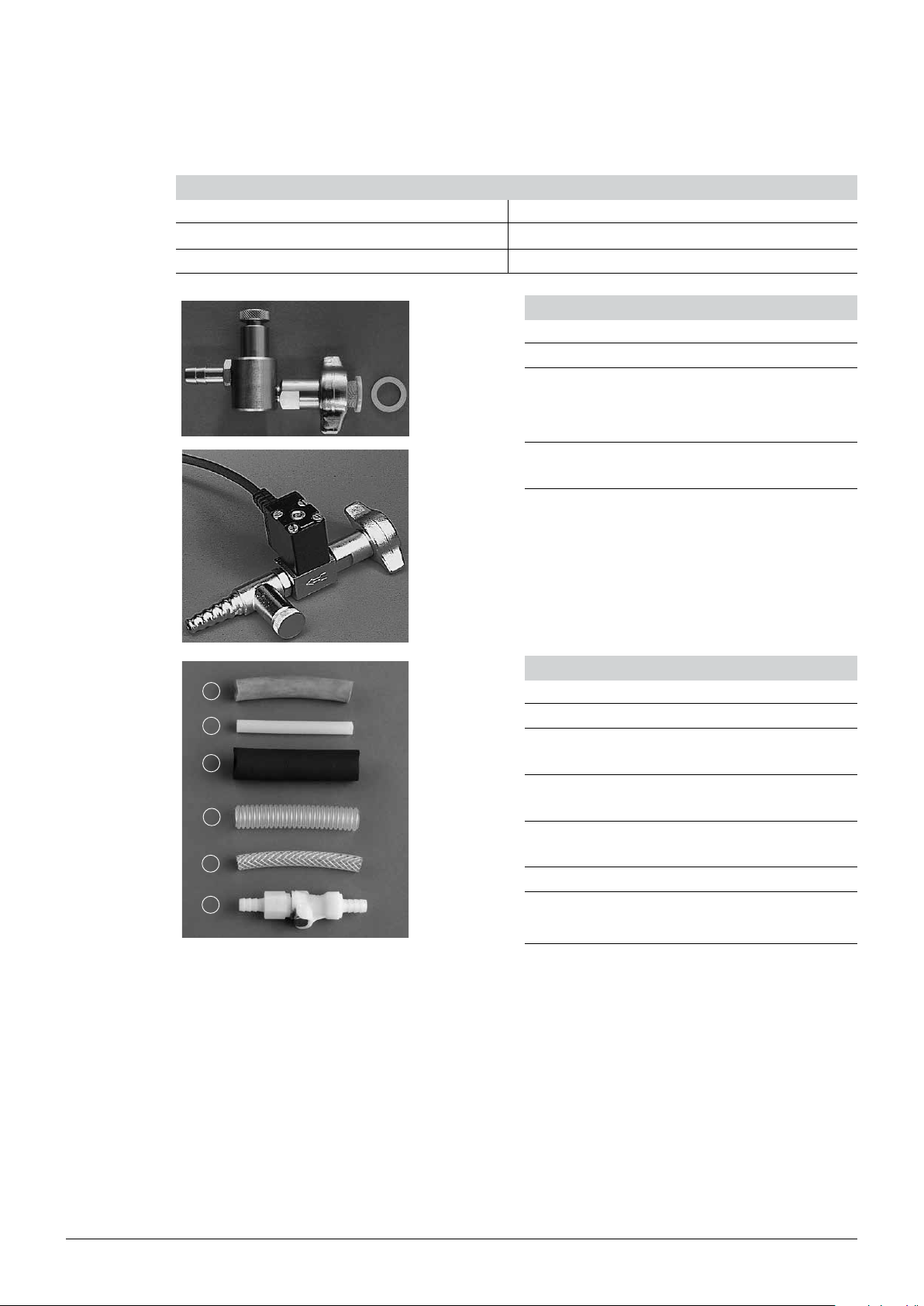
10.6 Miscellaneous
Table 10-12: Documentation
Product Order number Product Order number
Installation and Operation Guide 93163 Multivapor IQ/OQ, English 48822
Multivapor Application Booklet 48858
10 Spare parts
Table 10-13: Water control valves
Product Order number
Water control valve ½”, complete 11606
Cooling water valve 24 V for Vacuum
31356
Controller V-850/V-855
Table 10-14: Tubes
1
2
3
4
5
Product Order number
a Vacuum tube, 2 m, ø 16/6 mm 40459
b Cooling water silicone tube, 1.5 m,
43940
ø 9/6 mm
c Temperature insulation for cooling
28696
water tube, 1.5 m, ø 11/23 mm
d Ribbed PFA vacuum tube, 1 m
26096
(without SVL 22 joint)
e Nyflex tube, 5 m, ø 5/10 mm 43185
6
f Set of 2 quick couplings with stop
42885
flow mechanism
71 Multivapor™ Operation Manual, Version E
Page 72

10 Spare parts
Table 10-15: Vacuum solutions
Product Order number
Vacuum Controller V-850 47231
Vacuum Controller V-855 47232
Valve unit for combination of the
47160
Vacuum Controller V-850/V-855 with
non-BUCHI vacuum pumps
Table 10-16: Recirculating chiller
Product Order number
F-100, 230 V; 50/60 Hz (1400 W) 11056460
F-100, 115 V; 50/60 Hz (1400 W) 11056461
F-108, 230 V; 50/60 Hz (800 W) 11056464
F-108, 115 V; 50/60 Hz (800 W) 11056465
72 Multivapor™ Operation Manual, Version E
Page 73

11 Declarations and requirements
11.1 FCC requirements (for USA and Canada)
English:
This equipment has been tested and found to comply with the limits for a Class A digital device,
pursuant to both Part 15 of the FCC Rules and the radio interference regulations of the Canadian
Department of Communications. These limits are designed to provide reasonable protection against
harmful interference when the equipment is operated in a commercial environment.
This equipment generates, uses and can radiate radio frequency energy and, if not installed and used
in accordance with the instruction manual, may cause harmful interference to radio communications.
Operation of this equipment in a residential area is likely to cause harmful interference in which case
the user will be required to correct the interference at his own expense.
Français:
Cet appareil a été testé et s’est avéré conforme aux limites prévues pour les appareils numériques
de classe A et à la partie 15 des réglementations FCC ainsi qu’à la réglementation des interférences
radio du Canadian Department of Communications. Ces limites sont destinées à fournir une protection adéquate contre les interférences néfastes lorsque l’appareil est utilisé dans un environnement
commercial.
Cet appareil génère, utilise et peut irradier une énergie à fréquence radioélectrique, il est en outre
susceptible d’engendrer des interférences avec les communications radio, s’il n’est pas installé et
utilisé conformément aux instructions du mode d’emploi. L’utilisation de cet appareil dans les zones
résidentielles peut causer des interférences néfastes, auquel cas l’exploitant sera amené à prendre les
dispositions utiles pour palier aux interférences à ses propres frais.
11 Declarations and requirements
73 Multivapor™ Operation Manual, Version E
Page 74

11.2 Declaration of conformity
11 Declarations and requirements
74 Multivapor™ Operation Manual, Version E
Page 75

Page 76

Multivapor P-6/P-12
Operation Manual
Quality in your hands
Find your BUCHI Contacts:
BÜCHI L abor technik AG
CH – 9230 Fla wil 1
T +41 71 394 63 63
F +41 71 394 65 65
buchi@buchi.com
www.buchi.com
BÜCHI Labor technik G mbH
DE – 45127 Essen
Freeca ll 0800 414 0 414
T +49 201 747 490
F +49 201 747 492 0
deutschland@buchi.com
www.buechigmbh.de
BUCHI S arl
FR – 94656 Rungis Cedex
T +33 1 56 70 62 50
F +33 1 46 86 0 0 31
france@buchi.com
www.buchi.fr
BUCHI I talia S.r.l.
IT – 20010 Corn aredo (MI)
T +39 02 824 50 11
F +39 02 57 51 28 55
italia@buchi.com
www.buchi.it
BÜCHI Labortechnik GmbH
Branc h Office Benelu x
NL – 3342 GT
Hendrik-Ido-Ambacht
T +31 78 684 94 29
F +31 78 684 94 30
benelux@buchi.com
www.buch i.nl
BUCHI UK Ltd.
GB – Oldh am OL9 9QL
T +44 161 633 1000
F +44 161 633 1007
uk@buchi.com
www.buchi.co.uk
BUCHI H ong Kong Ltd.
HK – Centr al
T +852 2389 2772
F +852 2389 2774
china@buchi.com
www.b uchi.co m.cn
BUCHI Shanghai
CN – 200052 Shanghai
T +86 21 6280 3366
F +86 21 5230 8821
china@buchi.com
www.b uchi.co m.cn
BUCHI (Thailand) Ltd.
TH – Bangkok 10600
T +66 2 862 08 51
F +66 2 862 08 5 4
bacc@buchi.com
www.buchi.co.th
Nihon BUCHI K.K.
JP – Tokyo 110-0008
T +81 3 3821 4777
F +81 3 3821 4555
nihon@buchi.com
www.nihon-buchi.jp
BUCHI I ndia Private Ltd.
IN – Mumbai 400 055
T +91 22 667 75400
F +91 22 667 18986
india@buchi.com
www.buchi.in
PT. BUCHI Indonesia
ID – Tangerang 15321
T +62 21 537 62 16
F +62 21 537 62 17
indonesia@buchi.com
www.buchi.co.id
We are represented by more than 100 distribution partners worldwide.
Find your local representative at: www.buchi.com
BUCHI Korea Inc
KR – Seoul 153-782
T +82 2 6718 7500
F +82 2 6718 7599
korea@buchi.com
www.buch i.kr
BUCHI Corporation
US – New Cas tle,
Delaware 19720
Toll Free: +1 877 692 8244
T +1 302 652 3000
F +1 302 652 8777
us-sales@buchi.com
www.mybuchi.com
BUCHI Russia/CIS
United Machinery AG
RU – 127787 Moscow
T +7 495 36 36 495
F +7 495 981 05 20
russia@buchi.com
www.buch i.ru
093156 en 1112 / Technica l data are su bject to ch ange without notice/ Qual ity Syste ms ISO 90 01
The Eng lish vers ion is the o rigina l langua ge version and ser ves as basis for all translations into oth er langu ages.
 Loading...