

Page 1

Operation Manual
UV-Vis Detector
C�640
11593492
en
Page 2

Page 3

Table of contents
Table of contents
1 About this manual . . . . . . . . . . . . . . . . . . . . . . . . . . . . . . . . . . . . . . . 5
2 Safety. . . . . . . . . . . . . . . . . . . . . . . . . . . . . . . . . . . . . . . . . . . . . . 6
2.1 User qualification . . . . . . . . . . . . . . . . . . . . . . . . . . . . . . . . . . . . 6
2.2 Proper use . . . . . . . . . . . . . . . . . . . . . . . . . . . . . . . . . . . . . . . 6
2.3 Improper use . . . . . . . . . . . . . . . . . . . . . . . . . . . . . . . . . . . . . . 6
2.4 Safety warnings and safety signals used in this manual . . . . . . . . . . . . . . . . . 7
2.5 Product safety. . . . . . . . . . . . . . . . . . . . . . . . . . . . . . . . . . . . . . 9
2.5.1 General hazards. . . . . . . . . . . . . . . . . . . . . . . . . . . . . . . . . . . . . 9
2.5.2 Safety measures . . . . . . . . . . . . . . . . . . . . . . . . . . . . . . . . . . . 10
2.5.3 Built-in safety elements and measures . . . . . . . . . . . . . . . . . . . . . . . . 10
2.6 General safety rules . . . . . . . . . . . . . . . . . . . . . . . . . . . . . . . . . . 10
3 Technical data . . . . . . . . . . . . . . . . . . . . . . . . . . . . . . . . . . . . . . . . 11
3.1 Scope of application and delivery . . . . . . . . . . . . . . . . . . . . . . . . . . . 11
3.1.1 Standard instrument. . . . . . . . . . . . . . . . . . . . . . . . . . . . . . . . . . 11
3.1.2 Standard equipment . . . . . . . . . . . . . . . . . . . . . . . . . . . . . . . . . 12
3.2 Optional accessories . . . . . . . . . . . . . . . . . . . . . . . . . . . . . . . . . 13
3.3 Recommended spare parts . . . . . . . . . . . . . . . . . . . . . . . . . . . . . . 13
3.4 Technical specifications . . . . . . . . . . . . . . . . . . . . . . . . . . . . . . . . 14
3.5 Configuration of the analog cinch output . . . . . . . . . . . . . . . . . . . . . . . 15
3.6 Light sources . . . . . . . . . . . . . . . . . . . . . . . . . . . . . . . . . . . . . 15
3.6.1 Deuterium lamp . . . . . . . . . . . . . . . . . . . . . . . . . . . . . . . . . . . . 15
3.6.2 Halogen lamp . . . . . . . . . . . . . . . . . . . . . . . . . . . . . . . . . . . . . 15
3.7 Signals and parameters . . . . . . . . . . . . . . . . . . . . . . . . . . . . . . . . 16
3.7.1 Light intensity . . . . . . . . . . . . . . . . . . . . . . . . . . . . . . . . . . . . . 16
3.7.2 Range of wavelength . . . . . . . . . . . . . . . . . . . . . . . . . . . . . . . . . 16
3.7.3 Optical and electronical half width – spectral resolution . . . . . . . . . . . . . . . . 16
3.7.4 Time constant / data filtering . . . . . . . . . . . . . . . . . . . . . . . . . . . . . 16
3.7.5 Analog range ratio. . . . . . . . . . . . . . . . . . . . . . . . . . . . . . . . . . . 16
3.7.6 Display brightness. . . . . . . . . . . . . . . . . . . . . . . . . . . . . . . . . . . 16
3.7.7 Subscription / Remote or local control. . . . . . . . . . . . . . . . . . . . . . . . . 16
3.7.8 Scanning . . . . . . . . . . . . . . . . . . . . . . . . . . . . . . . . . . . . . . . 17
4 Description of function . . . . . . . . . . . . . . . . . . . . . . . . . . . . . . . . . . . 18
4.1 Front panel of the instrument . . . . . . . . . . . . . . . . . . . . . . . . . . . . . 18
4.1.1 LED status . . . . . . . . . . . . . . . . . . . . . . . . . . . . . . . . . . . . . . 18
Read this manual carefully before installing and running your system and note the safety precautions
in chapter 2 in particular. Store the manual in the immediate vicinity of the instrument, so that it can be
consulted at any time.
No technical modifications may be made to the instrument without the prior written agreement of
BUCHI. Unauthorized modifications may affect the system safety or result in accidents.
This manual is copyright. Information from it may not be reproduced, distributed, or used for competitive purposes, nor made available to third parties. The manufacture of any component with the aid of
this manual without prior written agreement is also prohibited.
If you need another language version of this manual, you can download available versions
at www.buchi.com.
3 C-640 Operation Manual, Version A
Page 4

Table of contents
4.1.2 Icons on the graphical display . . . . . . . . . . . . . . . . . . . . . . . . . . . . . 19
4.1.3 Push-buttons of the front panel . . . . . . . . . . . . . . . . . . . . . . . . . . . . 19
4.2 Connections at the rear panel . . . . . . . . . . . . . . . . . . . . . . . . . . . . . 19
4.3 The cell compartment . . . . . . . . . . . . . . . . . . . . . . . . . . . . . . . . . 20
4.3.1 Removing the cell . . . . . . . . . . . . . . . . . . . . . . . . . . . . . . . . . . . 21
4.3.2 Mounting the cell . . . . . . . . . . . . . . . . . . . . . . . . . . . . . . . . . . . 22
5 Putting into operation . . . . . . . . . . . . . . . . . . . . . . . . . . . . . . . . . . . . 23
5.1 Installation site. . . . . . . . . . . . . . . . . . . . . . . . . . . . . . . . . . . . . 23
5.2 Installing the Detector C-640 . . . . . . . . . . . . . . . . . . . . . . . . . . . . . 24
5.2.1 Electrical connections . . . . . . . . . . . . . . . . . . . . . . . . . . . . . . . . . 24
5.2.2 Connecting the communication cable . . . . . . . . . . . . . . . . . . . . . . . . . 24
5.2.3 Connecting the tubing. . . . . . . . . . . . . . . . . . . . . . . . . . . . . . . . . 25
5.3 Starting the detector . . . . . . . . . . . . . . . . . . . . . . . . . . . . . . . . . 26
5.4 Controlling the detector . . . . . . . . . . . . . . . . . . . . . . . . . . . . . . . . 27
5.4.1 The start up screens . . . . . . . . . . . . . . . . . . . . . . . . . . . . . . . . . 28
5.4.2 Switching the lamp on / off . . . . . . . . . . . . . . . . . . . . . . . . . . . . . . 28
5.4.3 Measuring / Zeroing . . . . . . . . . . . . . . . . . . . . . . . . . . . . . . . . . . 28
5.5 Parameter setup . . . . . . . . . . . . . . . . . . . . . . . . . . . . . . . . . . . 28
5.5.1 Wavelength . . . . . . . . . . . . . . . . . . . . . . . . . . . . . . . . . . . . . . 28
5.5.2 Time constant . . . . . . . . . . . . . . . . . . . . . . . . . . . . . . . . . . . . . 29
5.5.3 Half width . . . . . . . . . . . . . . . . . . . . . . . . . . . . . . . . . . . . . . . 29
5.5.4 Analog range ratio. . . . . . . . . . . . . . . . . . . . . . . . . . . . . . . . . . . 29
5.5.5 Display brightness. . . . . . . . . . . . . . . . . . . . . . . . . . . . . . . . . . . 29
5.6 Getting information and scanning . . . . . . . . . . . . . . . . . . . . . . . . . . . 30
5.6.1 General information . . . . . . . . . . . . . . . . . . . . . . . . . . . . . . . . . . 30
5.6.2 Intensity . . . . . . . . . . . . . . . . . . . . . . . . . . . . . . . . . . . . . . . . 30
5.6.3 Calibration menu . . . . . . . . . . . . . . . . . . . . . . . . . . . . . . . . . . . 30
5.6.4 Errors . . . . . . . . . . . . . . . . . . . . . . . . . . . . . . . . . . . . . . . . . 31
6 Maintenance and repairs . . . . . . . . . . . . . . . . . . . . . . . . . . . . . . . . . . 32
6.1 Customer service . . . . . . . . . . . . . . . . . . . . . . . . . . . . . . . . . . . 32
6.2 Housing condition . . . . . . . . . . . . . . . . . . . . . . . . . . . . . . . . . . . 32
6.3 Cleaning and replacement of the cell windows . . . . . . . . . . . . . . . . . . . . 32
6.3.1 Cleaning the cell window . . . . . . . . . . . . . . . . . . . . . . . . . . . . . . . 33
6.3.2 Replacing the cell windows . . . . . . . . . . . . . . . . . . . . . . . . . . . . . . 33
6.4 Replacement of the deuterium lamp. . . . . . . . . . . . . . . . . . . . . . . . . . 35
7 Troubleshooting . . . . . . . . . . . . . . . . . . . . . . . . . . . . . . . . . . . . . . . 37
7.1 Internal display error codes . . . . . . . . . . . . . . . . . . . . . . . . . . . . . . 37
7.2 Hardware error codes . . . . . . . . . . . . . . . . . . . . . . . . . . . . . . . . . 38
8 Shutdown, storage, transport and disposal . . . . . . . . . . . . . . . . . . . . . . . . 39
8.1 Storage and transport . . . . . . . . . . . . . . . . . . . . . . . . . . . . . . . . . 39
8.2 Disposal. . . . . . . . . . . . . . . . . . . . . . . . . . . . . . . . . . . . . . . . 39
9 Declarations and requirements. . . . . . . . . . . . . . . . . . . . . . . . . . . . . . . 40
9.1 FCC requirements (for USA and Canada) . . . . . . . . . . . . . . . . . . . . . . . 40
9.2 Declaration of conformity . . . . . . . . . . . . . . . . . . . . . . . . . . . . . . . 40
4 C-640 Operation Manual, Version A
Page 5

1 About this manual
This manual describes the UV-VIS Detector C-640. It provides all information required for its safe
operation and to maintain it in good working order. It is addressed to laboratory personnel in particular.
Abbreviations
FEP
Fluorelastomer
PTFE Polytetrafluoroethylene (Teflon)
1 About this manual
5 C-640 Operation Manual, Version A
Page 6

2 Safety
This chapter points out the safety concept of the instrument and contains general rules of behavior
and warnings from direct and indirect hazards concerning the use of the product.
For the users safety all safety instructions and the safety messages in the individual chapters shall
strictly be observed and followed. Therefore, the manual must always be available to all persons
performing the tasks described herein.
2.1 User qualification
The instrument may only be used by laboratory personnel and other persons, who on account of
training and professional experience know the dangers, which can develop when operating the
instrument.
Untrained personnel or persons, who are currently being trained, require careful supervision by a
qualified person. The present Operation Manual serves as a basis for training.
2 Safety
2.2 Proper use
The UV-VIS Detector C-640 has been designed and built as laboratory instrument.
It is able to detect and measure changes in the light absorption behavior of liquids passing through the
flow cell of the instrument. The absorption for four selected wavelengths is measured simultaneously
and scanning over the entire wavelength range of the detector (200 – 840 nm) becomes possible in
conjunction with the BUCHI SepacoreControl software and the control unit C-620.
A deuterium lamp acts as primary light source of the instrument, supported by a halogen lamp as
secondary light source. The communication between the C-620 control unit and the SepacoreControl
software is done via a serial RS232 cable (contained in the standard equipment). If the C-640 detector
shall be used without the C-620 control unit, it can be connected directly to the C-660 fraction
collector using the optional available cinch cable.
If the instrument is used with potentially toxic or hazardous substances, it has to be installed inside a
closed fume hood or glove box. In such case, the complete processing and system handling has to
be performed within the ventilated box to avoid toxication and other hazardous situations to the user
and the environment.
2.3 Improper use
Applications not mentioned in section 2.2 are considered to be improper. Applications which do not
comply with the technical data (see section 3 of this manual) are also considered to be improper.
The operator bears the sole risk for any damages or hazards caused by improper use!
The following uses are expressly forbidden:
• Installation or use of the instrument in rooms, which require ex-protected instruments.
6 C-640 Operation Manual, Version A
Page 7
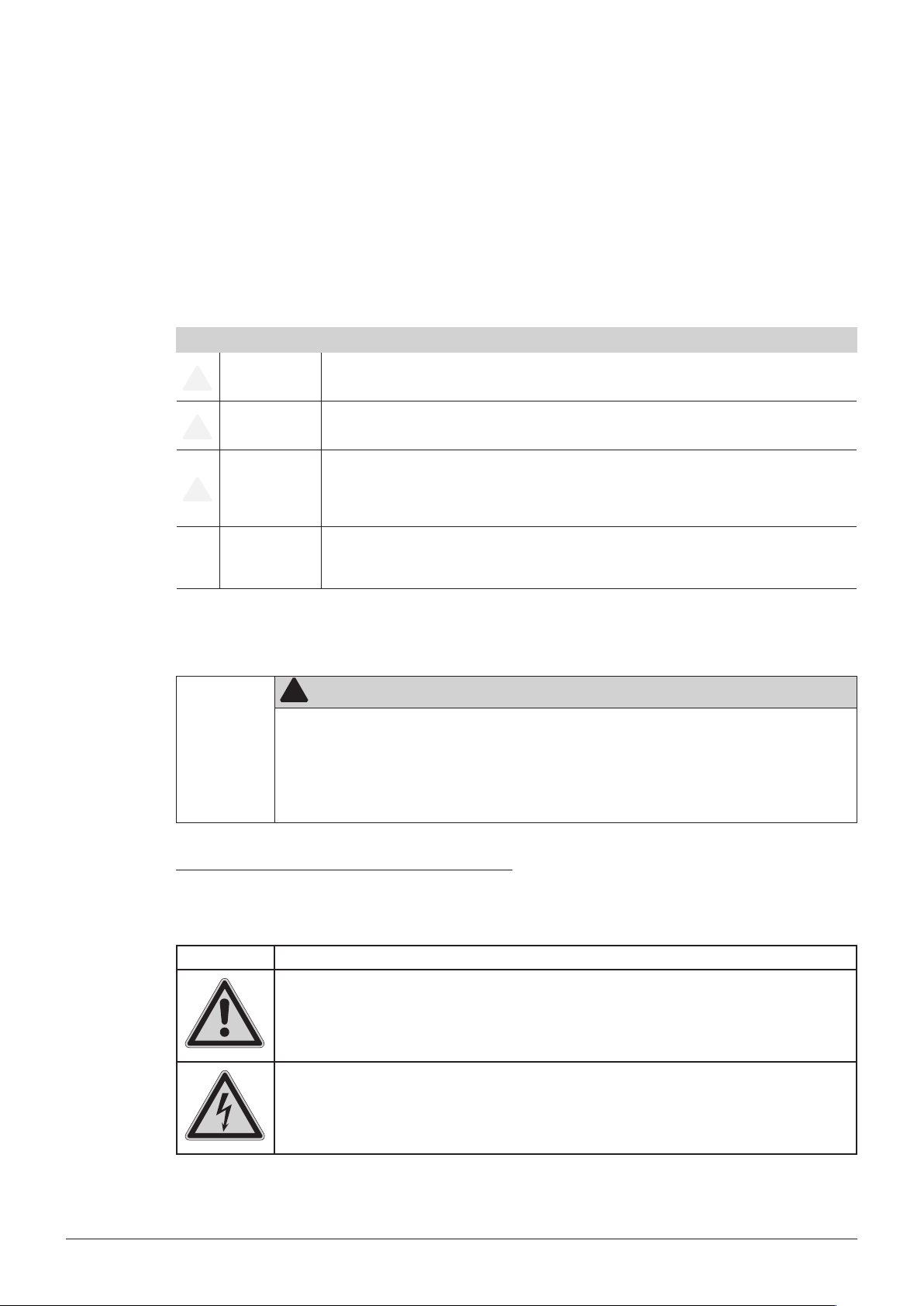
2.4 Safety warnings and safety signals used in this manual
DANGER, WARNING, CAUTION and NOTICE are standardized signal words for identifying risk levels,
related to personal injury and property damage. All signal words, which are related to personal injury
are accompanied by the general safety sign.
For your safety it is important to read and fully understand the below table with the different signal
words and their definitions!
Sign Signal word Definition Risk level
DANGER
Indicates a hazardous situation which, if not avoided, will result in
death or serious injury.
2 Safety
★★★★
WARNING
CAUTION
NOTICE
no
Supplementary safety information symbols may be placed in a rectangular panel on the left to the
signal word and the supplementary text (see below example).
Space for
supplementary
safety
information
symbols
Table of supplementary safety information symbols
The below reference list incorporates all safety information symbols used in this manual and their
meaning.
Indicates a hazardous situation which, if not avoided, could result
in death or serious injury.
Indicates a hazardous situation which, if not avoided, may result
in minor or moderate injury.
Indicates possible property damage, but no
practices related to personal injury.
!
SIGNAL WORD
Supplementary text, describing the kind and level of hazard / risk seriousness.
• List of measures to avoid the herein described, hazard or hazardous situation.
• ...
• ...
(property damage only)
★★★☆
★★☆☆
★☆☆☆
Symbol Meaning
General warning
Electrical hazard
7 C-640 Operation Manual, Version A
Page 8

Explosive gases, explosive environment
Harmful to live-forms
Device damage
Wear laboratory coat
2 Safety
Wear protective goggles
Wear protective gloves
Additional user information
Paragraphs starting with NOTE transport helpful information for working with the device / software or
its supplementaries. NOTEs are not related to any kind of hazard or damage (see example below).
NOTE
Useful tips for the easy operation of the instrument / software.
8 C-640 Operation Manual, Version A
Page 9

2.5 Product safety
Safety warnings in this manual (as described in section 2.4) serve to make the user alert and to avoid
hazardous situations emanating from residual dangers by giving appropriate counter measures.
However, risks to users, property and the environment can arise when the instrument is damaged,
used carelessly or improperly.
2.5.1 General hazards
The following safety messages show hazards of general kind which may occur when handling the
instrument. The user shall observe all listed counter measures in order to achieve and maintain the
lowest possible level of hazard.
Additional warning messages can be found whenever actions and situations described in this manual
are related to situational hazards.
2 Safety
!
Warning
Death or serious injuries by use in explosive environments.
• Do not operate the instrument in explosive environments.
• Do not operate the instrument with explosive gas mixtures.
!
Warning
Death or serious poisoning by contact or incorporation of harmful substances at use.
!
Warning
Death or serious injuries by contact with high voltage.
• Only open the housing of the product when instrument is switched off and unplugged.
Risk of instrument short-circuits and damage by liquids.
• Do not spill liquids over the instrument or parts of it.
• Wipe off any liquids instantly.
• Do not move the instrument when it is in use.
• Keep external vibrations away from the instrument.
9 C-640 Operation Manual, Version A
Notice
Page 10
2 Safety
Risk of instrument damage by wrong mains supply.
• External mains supply must meet the voltage given on the type plate.
• Check for sufficient grounding.
2.5.2 Safety measures
Always wear personal protective equipment such as protective eye goggles, protective clothing, and
gloves when working with the instrument.
2.5.3 Built-in safety elements and measures
High voltage and electrostatic charges
• Safety current limitation.
• Grounded housing to arrest electrostatic charges.
Notice
2.6 General safety rules
Responsibility of the operator
The head of laboratory is responsible for training his personnel.
The operator shall inform the manufacturer without delay of any safety-related incidents which might
occur during operation of the instrument. Legal regulations, such as local, state and federal laws
applying to the instrument must be strictly followed.
Duty of maintenance and care
The operator is responsible for the proper condition of instrument at use and that maintenance,
service and repair jobs are performed with care and on schedule by authorized personnel only.
Spare parts to be used
Use only genuine consumables and genuine spare parts for maintenance to assure good system
performance and reliability. Any modifications to the spare parts used are only allowed with the prior
written permission of the manufacturer.
Modifications
Modifications to the instrument are only permitted after prior consultation with and with the written
approval of the manufacturer. Modifications and upgrades shall only be carried out by an authorized
BUCHI technical engineer. The manufacturer will decline any claim resulting from unauthorized modifications.
10 C-640 Operation Manual, Version A
Page 11

3 Technical data
This chapter introduces the reader to the instrument and its specifications. It contains the scope of
delivery, technical data, requirements and performance data.
3.1 Scope of application and delivery
The UV-VIS Detector C-640 is available as powerful detector for the Sepacore system. It can be used
in conjunction with the SepacoreControl software, connected to the C-620 control unit or without the
use of the software, connected to the C-660 fraction collector.
The instrument can measure the change of the absorption behavior of a sample at four selected
wavelengths in the range of 200 to 840 nm.
In conjunction with the SepacoreControl software it is also able to scan the whole range of the spectrum continuously.
The scope and completeness of delivery can be checked according to section 3.1.2 Standard equipment. After unpacking please check the instrument and all accessories thoroughly for any damages!
3 Technical data
NOTE
For additional information about the listed products, see www.buchi.com or contact your local dealer.
3.1.1 Standard instrument
Table 3-1: Standard instrument
Product Order no.
UV-VIS Detector C-640
with preparative flow cell
Complete UV-VIS Detector C-640 system for use
in conjunction with the SepacoreControl software.
Complete with preparative flow cell, necessary cables
fittings and tubing.
11058148
11 C-640 Operation Manual, Version A
Page 12

3.1.2 Standard equipment
Each part listed with an order number can be ordered separately as spare part.
3 Technical data
Table 3-2: Standard equipment
Product Order no.
UV-VIS detector unit C-640
Preparative flow cell for C-640 11057949
Fitting and ferrule 1/8” (2 pcs. each) 044261
Fitting and ferrule 1/16” (2 pcs. each) 044262
12 C-640 Operation Manual, Version A
Page 13

3 Technical data
FEP tube inner diameter 1/16”, outer
diameter 1/8”
FEP tube inner diameter 1/32”, outer
diameter 1/16”
Test cell for preparative cell
CD containing Operating Instructions
en / de / fr / it / es / cn / jp
Power cord
044354
044357
3.2 Optional accessories
3.3 Recommended spare parts
RS232 cable
Table 3-3: Optional accessories
Product Order no.
Cinch cable 045216
For connecting the C-640 directly to the
C-660 fraction collector without using the
SepacoreControl software.
Table 3-4: Recommended spare parts
Product Order no.
Deuterium lamp for C-640 11058131
Spare part set preparative flow cell 11058231
13 C-640 Operation Manual, Version A
Page 14

3.4 Technical specifications
Table 3-5: Technical specifications
Average power consumption max. 90 W
Power supply voltage 100–240 VAC ± 10%
Frequency
Fuse 2.5 A / 250 V
Dimensions (w × d × h) 135 × 418 × 185 mm
Weight 6 kg
Wavelength range 200–840 nm (256 elements on CCD)
Typical spectral half width 10 nm
Accuracy of adjustment ± 1 nm
Reproducibility ± 0.5 nm
Noise level at test cell ± 5 x 10
Drift at test cell (254 nm after 1 h) 1 x 10
Time constant (T90) 0.5 s ; 0.75 s; 1 s or 2 s
Light source Deuterium discharge lamp / halogen lamp
Maximum flow rate 500 mL/min
Maximum pressure at the cell 20 bar / 290 psi
Output for integrator 1 V/AU (in digital form only)
Interface RS232
Installation category II
Degree of protection IP20
Pollution degree 2
Environmental conditions:
Temperature 5–40 °C for indoor use only
Altitude up to 2000 m
Humidity
3 Technical data
50 / 60 Hz
-5
AU at 254 nm, TC 0.75 s
-3
AU/h
max. relative humidity 80% for temperatures up to
31 °C, linearly decreasing to 50% at 40 °C
Table 3-6: Material and Approvals
Materials in contact with mobile phase PTFE / fused silica / stainless steel
Approvals CE, CSA
14 C-640 Operation Manual, Version A
Page 15

3.5 Configuration of the analog cinch output
Figure 3-1: Configuration of the cinch outputs (female)
3.6 Light sources
3.6.1 Deuterium lamp
3 Technical data
a Analog Output (HI)
Absorbance signal output. Voltage magnitude cor-
responds to the actual absorbance in the cell. The
conversion factor depends on the settings. Output
range is from -0.2 V to 1.2 V. The analog output is
single ended.
b GNA (Low)
Analog ground of the output signal. The analog
ground is connected to the instrument housing.
The primary light source of the detector C-640 is a deuterium lamp with an average lifespan of about
1000 operating hours.
A lamp test can be performed across the whole range of the detectable spectrum (Scan) or on the
four selected wavelengths of the detection channels (A–D) only.
Note
Aging of the deuterium lamp is correlated to the measured wavelengths, e.g. if the lamp is mainly
used in the range of 200 to 250 nm, the lifespan will be reduced.
To perform the test, assemble the black test cell to the cell compartment and measure the light intensity. The result can be interpreted according to the following table:
Measured light intensity Meaning Solution
> 50% Lamp is in good condition. No replacement of the lamp required.
> 10% but < 50% Lamp is working, but noise and drift of the
system may be higher. Starting the lamp
might get more and more problematic.
< 10% Lamp is at the end of its lifespan. The lamp needs to be replaced. (See
The lamp may be replaced to minimize
noise and drift. As soon as starting problems with the lamp occur, a replacement
of the lamp becomes necessary.
chapter 6.4 “Replacement of the deuterium lamp”.)
3.6.2 Halogen lamp
The secondary light source of the instrument is a halogen lamp. This lamp is always used together
with the deuterium lamp. Even if this lamp has a very big lifespan, a replacement of this lamp may
become necessary. A check for any damages is carried out during each initialization of the halogen
lamp. The replacement of the halogen lamp can only be performed by a specialist. Please contact
your local service.
15 C-640 Operation Manual, Version A
Page 16

3.7 Signals and parameters
3.7.1 Light intensity
The light intensity of a newly installed lamp used with the test cell is set to 100% on all wavelengths.
These values form the reference for later tests of the light intensity.
3.7.2 Range of wavelength
The wavelength range of the detector C-640 depends on the assembly of the optical parts, the
calibration results and the number of elements of the CCD sensor that are used at the same time for
processing (“electronic half width of wavelength”)
The default electronic half width of wavelength (HF = 4) results in a wavelength range from 200 to 840
nm. Increasing of the electronic half width of wavelength (HF) can decrease the wavelength range
(symmetric for both sides of the spectrum).
3.7.3 Optical and electronical half width – spectral resolution
3 Technical data
The base spectral resolution of the detector is based on the placement of each element of the CCD
sensor according to the placement of the lamp spectrum and the slit width. It is about 0.85 nm per
element while the slit width is a multiple of the size of one element. The slit width of the detector is 8 nm.
Multiple elements of the CCD sensor are used for signal processing at once. The total length of the
processing elements for one wavelength will affect the spectral resolution in a negative way. On the
other hand it will improve the dynamic range reduce the noise of the system. For these reasons the
adaption of the number of processing elements (“electronic half width of wavelength”) is optional
while the default value HF = 4 (8.4 nm) corresponds to the slit width and has a minimal effect on the
spectral resolution.
3.7.4 Time constant / data filtering
Processing of the raw absorbance signals is done according to the time constant of the detector.
Therefore a classic continuous time filtering is used. This kind of processing is done only for absorbance data but not for intensities or scanning of absorbance and intensities. For absorbance scans a
special low level time constant is used. Available values are 0.5 s, 0.75 s, 1.0 s and 2.0 s.
3.7.5 Analog range ratio
The available values are: 0.05 AU/V, 0.1 AU/V, 0.25 AU/V, 0.5 AU/V, 1 AU/V, 2 AU/V, 3 AU/V, and 5
AU/V.
3.7.6 Display brightness
The brightness of the display can be adapted to the following values:
12.5%, 25%, 37.5%, 50%, 62.5%, 75%, 87.5% and 100%.
3.7.7 Subscription / Remote or local control
Remote control means the device is controlled via the RS232 interface. Local control means the
detector is controlled using the keyboard and the graphical display of the detector itself.
Remote control starts immediately after the receipt of the first command via the RS232 interface and
is stopped after a time period of 4 seconds without any new command. For permanent remote control
a continuous communication with the detector (e.g. reading detector status) has to be established.
During subscription or remote control the instrument keyboard is locked but the graphical display still
shows the current measurement data.
16 C-640 Operation Manual, Version A
Page 17

3.7.8 Scanning
Scanning over the whole detection range causes a high workload on the detector and its communication lines. To keep the workload for the instrument as low as possible the sample measurement of the
four predefined wavelengths for the four analog outputs is omitted during a scan. This means during a
scan the measured values on to the analog outputs will not be updated - instead the last values from
the time before the scan started will be passed on till the scan is finished.
Note
The scanning functionality is only available if the detector is controlled by the SepacoreControl software.
3 Technical data
17 C-640 Operation Manual, Version A
Page 18

4 Description of function
This chapter explains the basic working principle of the UV-VIS Detector C-640. It also shows how the
instrument is structured and provides a general functional description of its assembly.
4.1 Front panel of the instrument
The front panel of the instrument consists of nine push buttons , two LED indicators b the ON /
OFF switch a and the graphical display .
2
4 Description of function
a Power switch ON / OFF
4
b LED indicators (Lamp = green and Error = red)
Push buttons for operating the instrument
Graphical display
3
Figure 4-1: Front panel of the instrument
4.1.1 LED status
LED LED status Description
LAMP Off The detector-lamp is off.
ERROR Off The detector has no error.
1
On The lamp is on.
NOTE
During start-up of the detector all LEDs will be switched on for a
short period of time.
Blinking The detector-lamp is starting up.
On An error occurred.
NOTE
During start-up of the detector all LEDs will be switched on for a
short period of time.
Blinking Indicates a display error.
18 C-640 Operation Manual, Version A
Page 19

4.1.2 Icons on the graphical display
Icon Meaning
If this icon of a small key is visible on the upper right corner of the display, the detector is remote-controlled by the software SepacoreControl while the communication
with the detector is established and the initial setup is performed. In this mode the
keypad of the detector is locked.
s
4.1.3 Push-buttons of the front panel
Push-button Function
Right Navigate right or jump to next subparameter.
Left Navigate left or jump to previous subparameter.
Up Navigate up or increase parameter value.
Down Navigate down or decrease parameter value .
ENTER Confirm Setting.
LAMP Switch detector lamp On / Off.
ZERO Start the autozero function.
MENU Enter configuration menu or navigate to next parameter.
ESCAPE Leave menu or cancel operation.
While the detector is controlled by the software and measured values are transferred
from the detector to the software, the detector is running in “subscription mode”, signalized by a small “s” in the upper right corner of the display. In this mode the keypad
of the detector is locked.
4 Description of function
4.2 Connections at the rear panel
3
Figure 4-2: Rear panel of the instrument
2
1
• a Main power connector with integrated
fuse (T 2.5 A)
• b RS 232 connector for connection to
the C-620 control unit
• 4 cinch connectors for analog
connection to fraction collector
19 C-640 Operation Manual, Version A
Page 20

4.3 The cell compartment
The cell compartment is located on the right side of the instrument:
4 Description of function
Figure 4-3: Cell compartment of the C-640
The cell itself is accessible from the right side of the instrument by opening the shutter which at the
same time functions as a quick clamping lever for holding the cell in place within the optical path.
Risk of instrument damage by wrong handling.
• Make sure you always place one hand underneath the cell when opening the shutter to
Notice
prevent the cell from falling down while it is released! (The correct proceeding can be taken
from the pictures in the following section.)
20 C-640 Operation Manual, Version A
Page 21

4.3.1 Removing the cell
For a safe removal of the cell from the cell compartment proceed as follows.
4 Description of function
- While opening the shutter with one hand, prevent the cell
from falling down by placing two fingers of the other hand
underneath of it.
- In most cases the cell will be set free as soon as the shutter
has been opened completely and can be taken away from
the cell compartment.
In case the cell didn’t come loose although the shutter is
already completely open, hold the cell in place with two
fingers.
- Press with one finger against the metal bar at the inside of
the shutter to set the cell free.
- The cell is released and can be taken away from the cell
compartment.
Figure 4-4: Removing the cell from the cell compartment
21 C-640 Operation Manual, Version A
Page 22

4.3.2 Mounting the cell
4 Description of function
- Enter the cell to the cell compartment, slide it onto the
groove on the left side of the compartment and hold it on
place with two fingers.
- Carefully close the shutter, observing the cell to be clamped
properly.
Figure 4-5: Mounting the cell
22 C-640 Operation Manual, Version A
Page 23

5 Putting into operation
This chapter describes how the instrument has to be installed. It also gives instructions for the initial
startup.
NOTE
Inspect the instrument for damages during unpacking. If necessary, prepare a status report immediately to inform the postal company, railway company or transportation company. Keep the original
packaging for future transportation.
5.1 Installation site
Put the instrument on a stable, horizontal surface. Consider the maximum product dimensions and
weight. We recommend the installation into the chromatography table. Obtain the environmental
conditions as described in section 3.4 “Technical specifications”.
5 Putting into operation
!
Warning
Death or serious injuries by use in explosive environments.
• Do not operate the instrument in explosive environments.
!
Warning
Death or serious poisoning by contact or incorporation of harmful substances.
• Wear safety goggles.
• Wear safety gloves.
• Wear a laboratory coat.
• Clean the instrument and all accessories thoroughly to remove possibly dangerous
substances.
• Do not clean dusty parts with compressed air.
• Store the instrument and its accessories at a dry place in its original packaging.
23 C-640 Operation Manual, Version A
Page 24

5.2 Installing the Detector C-640
5.2.1 Electrical connections
Verify that the electrical requirement of the detector, stated on the back plate of the instrument, corresponds to voltage of your local electrical network.
Make sure the main switch on the front side of the instrument is switched off, before you plug in the
power cord or a communication cable!
• Connect the power plug of the Detector to the mains supply using the power cable contained in
the standard delivery of the instrument.
Caution
!
Risk of instrument damage by wrong mains supply
• External mains supply must meet the voltage given on the back plate.
• Check for sufficient grounding.
5 Putting into operation
Additional electrical safety measures such as residual current
breakers may be necessary to meet local laws and regulations!
External connections and extension lines must be provided with an
earthed conductor lead (3-pole couplings, cord or plug equipment).
All used power cords shall be equipped with molded plugs only to
avoid risks due to unobservant defective wiring.
5.2.2 Connecting the communication cable
• Connect the C-640 detector to the C-620 control unit using the RS 232 cable included in the standard delivery of the instrument.
NOTE
If the detector shall not be controlled by the SepacoreControl software, connect up to two of the
four analog outputs (A , B, C , or D) to the C-660 fraction collector using the optional available cinch
cable (045216). The four analog outputs (A–D) are related to the four detectable wavelengths of the
detector. Only two of them can be connected to the C-660 fraction collector.
The configuration of the analog cinch outputs can be taken from Figure 3-1.
24 C-640 Operation Manual, Version A
Page 25

5.2.3 Connecting the tubing
Tubes with two different diameters are contained in the standard delivery of the instrument. The wider
one is 1/8” in outer diameter and 1/16” in inner diameter, the tighter one is 1/16” in outer diameter and
1/32” in inner diameter. Choose the tube with the corresponding inner diameter that fits the needs of
your application best and cut it into the required number of pieces each of the appropriate length.
The connection to the measurement cell is established using the diameter-specific bolted fittings.
Use the green fittings with the green ferrules (044261) for the 1/8” tubing and the grey fittings with the
grey ferrules (044262) for the 1/16” tubing.
NOTE
The tubing with 1/32” inner diameter together with the corresponding grey fittings can be used for
flow rates up to 30 mL/min. For flow rates higher than 30 mL/min the tubing with 1/16” inner diameter together with the green fittings shall be used.
5 Putting into operation
For 1/8” tubing
Figure 5-1: Attaching the bolted fittings to the tubing
- Slide one of the green fittings over a piece of the 1/8” tube
followed by the corresponding green ferrule (the tip of the
ferrule has to point to the thread of the fitting). The tip of the
tube should not overlap the ferrule too much.
For 1/16” tubing
- Slide one of the grey fittings over a piece of the 1/16” tube
followed by the corresponding grey ferrule (the tip of the
ferrule has to point to the thread of the fitting). The tip of the
tube should not overlap the ferrule too much.
25 C-640 Operation Manual, Version A
Page 26

5 Putting into operation
- Remove the white blanking plugs from the cell and connect
the column outlet to the lower cell inlet a by screwing in
the bolted fitting. (Using the lower inlet for the liquid coming
from the column makes the removal of air bubbles from the
2
cell a lot easier.)
- Connect the outlet tubing to the upper cell outlet b.
- If the detector is built into the chromatograph table, make
sure to guide both tubes through the side opening of the
cell compartment.
- As soon as the tubing is connected to the cell, close the
shutter carefully and check all connections for leakage.
1
Figure 5-2: Attaching the tubing to the cell
!
Death or serious poisoning by contact or incorporation of harmful substances.
• Wear safety goggles.
• Wear safety gloves.
• Wear a laboratory coat.
• Check all connections for leakage after each installation.
• Check all connections for leakage on a regular base during operation.
• Clean the instrument and all accessories thoroughly to remove possibly dangerous
substances.
5.3 Starting the detector
• If you have installed the detector in accordance with the previous chapters, switch on the pump,
and check all connections of the cell for leaking liquid. Eliminate all leaks before you proceed.
• Switch on the instrument using the main switch on the front panel.
• Turn on the lamp.
• Observe stabilization of the zero line on the PC (if used) or on the graphical display of the instru-
ment under a continuous flow of liquid (mobile phase or ethanol) through the cell.
• After a time period of approximately 10 to 15 minutes the instrument should have stabilized. Press
zero to perform the auto zero function.
• In order to remove potential bubbles, we recommend to connect a back pressure regulator
(044337) at the outlet of the flow cell.
• The instrument is now ready for operation.
Warning
26 C-640 Operation Manual, Version A
Page 27

5.4 Controlling the detector
constant
dt
o
The detector can be controlled in two ways:
• in local control mode using the keypad and the graphical display of the instrument itself or
• in remote control via the RS232 interface using the software SepacoreControl.
The SepacoreControl offers full support for the detector and the detector can be controlled in a very
convenient way. Furthermore the use of the scan functionality over the full detection range of the
instrument is only provided by the SepacoreControl software.
The instrument can be switched from local control to remote control and vice versa at any time. In
remote or subscription mode the keypad of the instrument will be locked, signalized by a small key or
a small “s” in the graphical display of the instrument.
The menu structure of the instrument can be taken from the following schema:
STA RT
5 Putting into operation
Intro
START - UP SEQUENCE
MENU
Wavelengths
MENU
PARAMETER
MENU
General
INFO
MENU
Inf
Scan Info
MENU
CALIBRATION
Figure 5-3: Menu structure of the detector
ESC
Time
Intensity
ESC
Calib. Lamp
time
Half
wi
Calibration
Calib.
intensity
Analog range
h
Press 3 sec ENTER
ratio
Calib.
sensitivity
Display
Brightness
Calib. Std.
sens.
All parameters of the detector can be adapted in a corresponding submenu. The menu can be
entered by pressing the MENU button from any main screen. Pressing MENU again will switch to the
next parameter screen. Using the buttons LEFT and RIGHT it is possible to navigate through all sub
27 C-640 Operation Manual, Version A
Page 28

parameters of each screen (e.g. through the different wavelengths). The value of a parameter can be
increased or decreased by using the UP and DOWN buttons. If a button is held down for more than
0.5 seconds the automatic repetition will start, if it is held down for more than 3 seconds, the repeti-
tion will become faster. This feature is mainly thought for adapting the values for the wavelengths.
By pressing the ENTER button a value is stored. By pressing ESCAPE it is possible to leave any menu
and switch back to the main screen.
5.4.1 The start up screens
5 Putting into operation
During start-up of the detector an intro screen, showing
version and date of the instrument firmware is displayed
for a few seconds.
After start-up is completed and all parameters are
restored according to the last settings, the idle screen,
showing the state of the detector and the operating
hours of the lamp, is displayed.
5.4.2 Switching the lamp on / off
5.4.3 Measuring / Zeroing
5.5 Parameter setup
For more information about the parameters refer to the chapter 3.7 “Signals and parameters”.
The lamp can be switch on or off using the LAMP
button on the keypad of the detector.
Note
When switching the lamp off, an additional dialog has to
be confirmed with the ENTER button.
While the lamp is on, the measuring screen shows the
wavelength and absorbances for all channels. Using the
ZERO button an autozero procedure can be performed.
Note
There is no progress shown on the screen while the
autozero procedure is performed.
5.5.1 Wavelength
28 C-640 Operation Manual, Version A
Within this menu the wavelength for all available channels can be set.
See also chapter 3.7.2 “Range of wavelength”.
Page 29

5.5.2 Time constant
5.5.3 Half width
5.5.4 Analog range ratio
5 Putting into operation
Within this menu the time constant in seconds can be
set for all available channels.
See also chapter 3.7.4 “Time constant / data filtering”.
Within this menu the electronic half width of the instrument can be set.
See also chapter 3.7.3 “Optical and electronical half
width - spectral resolution”.
Within this menu the absorbance range for all channels
of the analog output (1V) can be set.
5.5.5 Display brightness
See also chapter 3.7.5 “Analog range ratio”.
Within this menu the brightness of the graphical display
can be adapted.
See also chapter 3.7.6 “Display brightness”.
29 C-640 Operation Manual, Version A
Page 30

5.6 Getting information and scanning
5.6.1 General information
5.6.2 Intensity
5 Putting into operation
The General info menu provides basic information about
the detector. Use the buttons UP and DOWN to navigate
through the different items.
The following information can be retrieved from this
menu:
Serial number, firmware version, firmware date, lamp
hours, available range of wavelength, subscription
frequency, model, Software and hardware version.
The Intensity info menu provides information about the
current light intensity on all channels.
5.6.3 Calibration menu
See also chapter 3.7.1 “Light intensity”.
To enter the Calibration menu press ENTER for 3
seconds.
Press ENTER to set the scan range and to enter scanning.
To reset the accumulated operating hours of the lamp
press ENTER.
Insert the test cell to the cell compartment and press
ZERO. Follow the instructions given on the display.
Set the Wavelength (WL) and press ENTER. Follow the
instructions given on the display.
Press DOWN to perform a standard calibration.
Follow the instructions given on the display.
30 C-640 Operation Manual, Version A
Page 31

5.6.4 Errors
5 Putting into operation
If any kind of error occurs during operation of the detector an error description together with a corresponding error number will be displayed on the graphical display. (It might be necessary to scroll
through the error description if it does not fit onto the screen all at once.)
If more than one error occurs at once, the description text will only reflect the most significant failure.
In addition to the speaking error description, error codes in form of hexadecimal numbers ending with
the letter “h” are displayed.
Two different kinds of error screens can be displayed:
Error screen for a hardware failure.
Error screen for an internal error.
31 C-640 Operation Manual, Version A
Page 32

6 Maintenance and repairs
This chapter gives instructions on maintenance work to be performed in order to keep the instrument
in good and safe working condition. All maintenance and repair work requiring the opening or removal
of the instrument housing must be carried out by trained personnel only!
Note
Use only genuine consumables and spare parts for any maintenance and repair work in order to
assure warranty and continued system performance.
6.1 Customer service
Only authorized service personnel are allowed to perform repair work on the instrument. Authorization requires a comprehensive technical training and knowledge of possible dangers which might arise
when working at the instrument. Such training and knowledge can only be provided by BUCHI.
6 Maintenance and repairs
Addresses of official BUCHI customer service offices are given on the BUCHI website under:
www.buchi.com. If malfunctions occur on your instrument or you have technical questions or application problems, contact one of these offices.
The customer service offers the following:
• Spare part delivery
• Repairs
• Technical advice
6.2 Housing condition
Check the housing for visible defects (switches, plugs, display) and clean it regularly with a damp
cloth.
6.3 Cleaning and replacement of the cell windows
Wear laboratory coat.
Wear protective goggles.
Wear protective gloves.
32 C-640 Operation Manual, Version A
Page 33

6.3.1 Cleaning the cell window
A contaminated cell will result in a lowered light transmission which will increase the noise level and
will make zeroing difficult. The easiest way to clean the cell is to rinse the dismantled cell with suitable
solvents. Therefore the cell has be removed from the instrument. The solvent type has to be chosen
according to the type of the contamination. Either organic or inorganic solvents, or diluted solutions of
acids (e.g. H2SO4 or HNO3 diluted with distilled water in ratio 1 : 20 or 1 : 10) may be used.
After cleaning rinse the cell with pure solvent and remount it to the cell compartment and check for
any leaks while liquid is flowing through the cell.
If the system is tight perform a cell test.
If this simple cleaning procedure did not solve the problem, contact the BUCHI service support or
replace the cell windows.
6.3.2 Replacing the cell windows
If a replacement of cracked or contaminated windows becomes necessary or if the optical path of the
preparative cell shall be changed you have to disassemble the cell:
• Remove the four screws a and the nuts b.
• Take away the cell covers .
• Take away the window cover .
• Carefully remove the cell window .
• Take away the PTFE sealings .
6 Maintenance and repairs
3
2
Figure 6-1: Disassembling the cell
Note
To facilitate the removal of the cell window, the pressure inside of the cell can be carefully increased
by the use of a dry syringe.
4
Risk of instrument damage by wrong handling.
• Never touch the cell windows with bare hands. Fingerprints will block the passage of UV
6
5
6
5
3
4
Notice
radiation through the cell window and may damage the surface of the cell window!
1
Insert new cell windows and (if necessary) new PTFE sealings and reassemble the cell in reversed
order as described above.
33 C-640 Operation Manual, Version A
Page 34

6 Maintenance and repairs
Note
To change the thickness of the liquid layer (the optical path) between the two cell windows, one or
both windows can be reassembled in a different orientation. (See Figure 6-2)
By default the optical path through the cell window is adapted to 0.3 mm according to schema a
in figure 6-2. For samples with lower concentration the length of the optical path can be increased
according to schema b and c.
a) b) c)
0.1 - 0.4 mm 1.1 - 1.4 mm 2.1 - 2.4 mm
Figure 6-2: Adjustment of the optical path
After assembly, carefully tighten the screws crosswise using a watchmaker’s screwdriver.
Risk of instrument damage by wrong handling.
• Do not use too much force while tightening the screws - otherwise the cell windows may
Before installing the reassembled cell to the cell compartment carefully check the cell for any impurities
(dust, hairs) using a magnifier. (Any impurity within the cell will increase the signal noise.)
After installing the cell into the cell compartment perform a leakage test.
Notice
break! Only use a watchmaker’s screwdriver which does not allow a too high momentum.
34 C-640 Operation Manual, Version A
Page 35

6.4 Replacement of the deuterium lamp
!
Warning
Death or serious injuries by contact with high voltage.
• This operation may only be carried out by a qualified person!
• Only open the housing of the product while the instrument is switched off and unplugged. Let
the lamp cool down for at least 15 minutes after switching the instrument off.
• The instrument may not be reconnected to the power supply before the housing has been
closed properly!
!
Warning
UV light is harmful for your eyes.
During routine operation of the instrument with fitted housing and closed shutter the UV light is
perfectly shielded.
• Only open the housing of the product when the instrument is switched off and unplugged and
do not put it back into operation while the housing is removed or the shutter is open!
6 Maintenance and repairs
Notice
Risk of instrument damage by wrong handling.
• Never touch the glass parts of the lamp with bare fingers. Fingerprints on the lamp will irreversibly damage the lamp when it is switched on.
After the instrument has been switched off and unplugged proceed as follows:
- Remove the four screws that fix the housing. (Two screws
at the right side and two screws at the left side of the housing.)
Note
The screw on the rear left side (marked with a voltage
sticker) is equipped with an additional washer for grounding
of the housing. This washer has to be placed between the
inner side of the housing and the chassis of the instrument.
- After removal of the four screws, the housing can be carefully lifted and tilted over to the backside of the instrument.
1
Note
Remove the green grounding cable a from its contact on
the inner side of the housing before you take the housing
completely away from the instrument.
35 C-640 Operation Manual, Version A
Page 36

6 Maintenance and repairs
- Loosen the screw a on the lamp holder just so far that the
lamp holder becomes turnable.
1
- Turn the bottom of the lamp holder slightly in your direction
(see next picture) so that the two screws holding the lamp
become accessible.
- Unscrew the two screws a and b at the bottom of the
lamp holder and take them away.
1
2
Note
The deuterium lamp has a small groove on one a side that
fits a small metal pin on the lamp holder
1
correct positioning of the lamp in the lamp holder.
b, guaranteeing a
2
- Carefully pull the lamp out of the lamp holder and disconnect the quick coupling of the cable, the lamp is connected
to. Replace the lamp by a new one and assemble it, following these instructions in reverse order.
Note
Never touch the glass parts of the lamp with bare fingers!
After the lamp has been replaced successfully, switch the
instrument on, allowing the lamp to stabilize for approximately one hour. After that the lamp life time and the light
intensity can be adapted in the calibration menu.
Figure 6-3: Removing the deuterium lamp from the instrument
Notice
Risk of instrument damage by wrong handling.
• After correct assembly of the replacement lamp don’t forget to reattach the grounding cable
to the housing and make sure no cable extends to one of the fan housings on the back side of
the instrument before fixing the housing.
36 C-640 Operation Manual, Version A
Page 37

7 Troubleshooting
Problem Caused by / Conditions Solution
After switching the unit on no LED on
the front panel is lit.
Increased noise and drift. Leaking cell, dirty cell, bubbles,
Leaking cell. Broken window, or leaking seal. Repair or replace the cell - see
Warning or error message. - See next two sub-chapters. Try
After switching the unit on the
display is not working and the red
LED (ERROR) blinks.
7 Troubleshooting
Failure of the power line fuse. Check the fuse.
(The fuse is integrated in the main
power connector on the backside of
the instrument.)
Electronics failure. Call service center.
Perform Cell test with lamp test
non-transparent mobile phase, old or
bad lamp.
Electronics / Optics failure. Call service center.
Display electronics / power supply
failure.
included.
Check cell connections.
Check mobile phase.
Check cell purity manually.
Install pressure regulator.
chapter 6.3 “Cleaning and replace-
ment of cell windows”.
resetting the error. If resetting does
not solve the problem, call the
service center.
Call service center.
7.1 Internal display error codes
Any failure in conjunction with the internal communication of the detector or its display electronics is
considered as internal error. Any time an internal error occurs the red ERROR LED blinks.
Code Meaning Repair
01h Power is down! Call service center.
02h Non-volatile memory failure! Call service center.
04h Digital-analog converter failure! Call service center.
08h Display failure! Call service center.
10h Detector communication failure! Call service center.
20h Detector communication timeout! Call service center.
40h Interface device failure! Call service center.
37 C-640 Operation Manual, Version A
Page 38

7.2 Hardware error codes
All errors related to a faulty hardware part of the detector are considered as hardware errors. Hardware errors are mainly detected based on physical values that are out of the working range of the
instrument.
In case an error code is displayed and the problem cannot be solved by switching the instrument off
and on again, please note down the 8 digit error code ending with “h” and contact the service center.
7 Troubleshooting
38 C-640 Operation Manual, Version A
Page 39

8 Shutdown, storage, transport and disposal
8 Shutdown, storage, transport and disposal
This chapter instructs how to shut down and to pack the instrument for storage or transport. Specifications for storage and shipping conditions can also be found listed here.
8.1 Storage and transport
Switch off the instrument and remove the power cord. Disconnect all cables and tubings and remove
all liquids and dusty residues before packaging the instrument.
!
Warning
Death or serious poisoning by contact or incorporation of harmful substances.
• Wear safety goggles.
• Wear safety gloves.
• Wear a laboratory coat.
• Clean the instrument and all accessories thoroughly to remove possibly dangerous
substances.
• Do not clean dusty parts with compressed air.
• Store the instrument and its accessories at a dry place in its original packaging.
8.2 Disposal
You have to follow valid regional and local laws concerning disposal. For help, please contact your
local authorities!
39 C-640 Operation Manual, Version A
Page 40

9 Declarations and requirements
9.1 FCC requirements (for USA and Canada)
English:
This equipment has been tested and found to comply with the limits for a Class A digital device,
pursuant to both Part 15 of the FCC Rules and the radio interference regulations of the Canadian
Department of Communications. These limits are designed to provide reasonable protection against
harmful interference when the equipment is operated in a commercial environment.
This equipment generates, uses and can radiate radio frequency energy and, if not installed and used
in accordance with the instruction manual, may cause harmful interference to radio communications.
Operation of this equipment in a residential area is likely to cause harmful interference in which case
the user will be required to correct the interference at his own expense.
Français:
Cet appareil a été testé et s’est avéré conforme aux limites prévues pour les appareils numériques
de classe A et à la partie 15 des réglementations FCC ainsi qu’à la réglementation des interférences
radio du Canadian Department of Communications. Ces limites sont destinées à fournir une protection adéquate contre les interférences néfastes lorsque l’appareil est utilisé dans un environnement
commercial.
Cet appareil génère, utilise et peut irradier une énergie à fréquence radioélectrique, il est en outre
susceptible d’engendrer des interférences avec les communications radio, s’il n’est pas installé et
utilisé conformément aux instructions du mode d’emploi. L’utilisation de cet appareil dans les zones
résidentielles peut causer des interférences néfastes, auquel cas l’exploitant sera amené à prendre les
dispositions utiles pour palier aux interférences à ses propres frais.
9 Declarations and requirements
9.2 Declaration of conformity
40 C-640 Operation Manual, Version A
Page 41

8 Shutdown, storage, transport and disposal
41 C-640 Operation Manual, Version A
Page 42

9 Declarations and requirements
42 C-640 Operation Manual, Version A
Page 43

Page 44

BÜCHI Labortechnik AG
CH-9230
T +41 71 394 63 63
F +41 71 394 65 65
Flawil 1 / Switzerland
www.buchi.com Quality in your hands
 Loading...