

Page 1

en
96962
Operation Manual
Pump Controller C�610 / Pump Manager C�615
Pump Modules C�601 & C�605
Page 2

Page 3

Table of contents
3
Pump Combinations Operation Manual, Version E
Table of contents
1 About this manual . . . . . . . . . . . . . . . . . . . . . . . . . . . . . . . . . . . . . . .5
1.1 Reference documents. . . . . . . . . . . . . . . . . . . . . . . . . . . . . . . . . .5
1.2 Trademarks . . . . . . . . . . . . . . . . . . . . . . . . . . . . . . . . . . . . . . . 5
1.3 Abbreviations . . . . . . . . . . . . . . . . . . . . . . . . . . . . . . . . . . . . . . 5
2 Safety. . . . . . . . . . . . . . . . . . . . . . . . . . . . . . . . . . . . . . . . . . . . . .6
2.1 User qualification . . . . . . . . . . . . . . . . . . . . . . . . . . . . . . . . . . . . 6
2.2 Proper use . . . . . . . . . . . . . . . . . . . . . . . . . . . . . . . . . . . . . . . 6
2.3 Improper use . . . . . . . . . . . . . . . . . . . . . . . . . . . . . . . . . . . . . . 6
2.4 Warning notices used in this manual . . . . . . . . . . . . . . . . . . . . . . . . . . 7
2.5 Product safety. . . . . . . . . . . . . . . . . . . . . . . . . . . . . . . . . . . . . .7
2.5.1 Instrument-related hazards . . . . . . . . . . . . . . . . . . . . . . . . . . . . . . . 7
2.5.2 Other hazards . . . . . . . . . . . . . . . . . . . . . . . . . . . . . . . . . . . . . .8
2.5.3 Safety measures . . . . . . . . . . . . . . . . . . . . . . . . . . . . . . . . . . . . 8
2.5.4 Safety elements . . . . . . . . . . . . . . . . . . . . . . . . . . . . . . . . . . . . .8
2.6 General safety rules . . . . . . . . . . . . . . . . . . . . . . . . . . . . . . . . . . . 8
3 Technical data . . . . . . . . . . . . . . . . . . . . . . . . . . . . . . . . . . . . . . . . . 9
3.1 Scope of delivery . . . . . . . . . . . . . . . . . . . . . . . . . . . . . . . . . . . . 9
3.1.1 Basic instruments . . . . . . . . . . . . . . . . . . . . . . . . . . . . . . . . . . . . 9
3.1.2 Standard accessories . . . . . . . . . . . . . . . . . . . . . . . . . . . . . . . . . 10
3.1.3 Optional accessories . . . . . . . . . . . . . . . . . . . . . . . . . . . . . . . . . 11
3.2 Materials used. . . . . . . . . . . . . . . . . . . . . . . . . . . . . . . . . . . . . 12
3.3 Technical data overview . . . . . . . . . . . . . . . . . . . . . . . . . . . . . . . . 13
4 Description of function . . . . . . . . . . . . . . . . . . . . . . . . . . . . . . . . . . . 15
4.1 Functional principle . . . . . . . . . . . . . . . . . . . . . . . . . . . . . . . . . . 15
4.2 Operative range of the pump systems. . . . . . . . . . . . . . . . . . . . . . . . . 16
5 Putting into operation . . . . . . . . . . . . . . . . . . . . . . . . . . . . . . . . . . . . 17
5.1 Installation site. . . . . . . . . . . . . . . . . . . . . . . . . . . . . . . . . . . . . 17
5.2 Electrical connections . . . . . . . . . . . . . . . . . . . . . . . . . . . . . . . . . 17
5.3 Installation. . . . . . . . . . . . . . . . . . . . . . . . . . . . . . . . . . . . . . . 18
5.3.1 Installating the standard accessories . . . . . . . . . . . . . . . . . . . . . . . . . 18
5.3.2 Pump system 1: Pump Controller C-610 and 1 Pump Module C-601 . . . . . . . . . 19
5.3.3 Pump system 2: Pump Manager C-615 and 1 Pump Module C-601 or C-605 . . . . 21
5.3.4 Pump system 3: Pump Manager C-615 and 2 Pump Modules C-601 or C-605. . . . 23
5.3.5 Pump system 4: Control Unit C-620 and 2 - 4 Pump Modules C-601 or C-605. . . . 25
Read this manual carefully before installing and running your system and note the safety precautions
in chapter 2 in particular. Store the manual in the immediate vicinity of the instrument, so that it can be
consulted at any time.
No technical modifications may be made to the instrument without the prior written agreement of
BUCHI. Unauthorized modifications may affect the system safety or result in accidents.
This manual is copyright. Information from it may not be reproduced, distributed, or used for competitive purposes, nor made available to third parties. The manufacture of any component with the aid of
this manual without prior written agreement is also prohibited.
The English manual is the original language version and serves as basis for all translations
into other languages. Other language versions can be downloaded at www.buchi.com.
Page 4

Table of contents
4
Pump Combinations Operation Manual, Version E
6 Operation . . . . . . . . . . . . . . . . . . . . . . . . . . . . . . . . . . . . . . . . . . 26
6.1 Pump system 1: Pump Controller C-610 and 1 Pump Module C-601 . . . . . . . . . 26
6.1.1 Controls of the Pump Controller . . . . . . . . . . . . . . . . . . . . . . . . . . . . 26
6.1.2 Operation . . . . . . . . . . . . . . . . . . . . . . . . . . . . . . . . . . . . . . . 26
6.2 Pump system 2, 3: Pump Manager C-615 and 1 - 2 Pump Modules C-601/605 . . . 27
6.2.1 Controls of the Pump Manager . . . . . . . . . . . . . . . . . . . . . . . . . . . . 27
6.2.2 Display . . . . . . . . . . . . . . . . . . . . . . . . . . . . . . . . . . . . . . . . 27
6.2.3 Operation . . . . . . . . . . . . . . . . . . . . . . . . . . . . . . . . . . . . . . . 28
6.2.4 Systematics of the Menu Mode . . . . . . . . . . . . . . . . . . . . . . . . . . . . 29
6.2.5 Parameters . . . . . . . . . . . . . . . . . . . . . . . . . . . . . . . . . . . . . . 30
6.2.6 Programming . . . . . . . . . . . . . . . . . . . . . . . . . . . . . . . . . . . . . 31
6.3 Pump system 4: Control Unit C-620 and 2,3 or 4 C-601 or C-605 . . . . . . . . . . 33
6.4 Calibration. . . . . . . . . . . . . . . . . . . . . . . . . . . . . . . . . . . . . . . 34
6.4.1 Calibration of the Pump Controller C-610 . . . . . . . . . . . . . . . . . . . . . . . 34
6.4.2 Calibration of the Pump Manager C-615 . . . . . . . . . . . . . . . . . . . . . . . 35
7 Maintenance . . . . . . . . . . . . . . . . . . . . . . . . . . . . . . . . . . . . . . . . . 36
7.1 System cleaning. . . . . . . . . . . . . . . . . . . . . . . . . . . . . . . . . . . . 36
7.2 Housing . . . . . . . . . . . . . . . . . . . . . . . . . . . . . . . . . . . . . . . . 36
7.3 Tube connections . . . . . . . . . . . . . . . . . . . . . . . . . . . . . . . . . . . 36
7.4 Sealing system . . . . . . . . . . . . . . . . . . . . . . . . . . . . . . . . . . . . 36
7.5 Pressure sensors . . . . . . . . . . . . . . . . . . . . . . . . . . . . . . . . . . . 36
7.5.1 Cleaning the seals. . . . . . . . . . . . . . . . . . . . . . . . . . . . . . . . . . . 37
7.5.2 Changing the seals . . . . . . . . . . . . . . . . . . . . . . . . . . . . . . . . . . 37
7.6 Piston backrinsing. . . . . . . . . . . . . . . . . . . . . . . . . . . . . . . . . . . 38
7.7 Changing the valves. . . . . . . . . . . . . . . . . . . . . . . . . . . . . . . . . . 38
7.8 Changing the suction and pressure tubing . . . . . . . . . . . . . . . . . . . . . . 39
8 Troubleshooting . . . . . . . . . . . . . . . . . . . . . . . . . . . . . . . . . . . . . . . 40
8.1 Malfunctions and their remedy. . . . . . . . . . . . . . . . . . . . . . . . . . . . . 40
8.2 Pulsation of a pump module. . . . . . . . . . . . . . . . . . . . . . . . . . . . . . 42
8.3 Customer service . . . . . . . . . . . . . . . . . . . . . . . . . . . . . . . . . . . 43
9 Shutdown, storage, transport and disposal . . . . . . . . . . . . . . . . . . . . . . . . 44
9.1 Storage and transport . . . . . . . . . . . . . . . . . . . . . . . . . . . . . . . . . 44
9.2 Disposal. . . . . . . . . . . . . . . . . . . . . . . . . . . . . . . . . . . . . . . . 44
10 Spare parts. . . . . . . . . . . . . . . . . . . . . . . . . . . . . . . . . . . . . . . . . . 45
11 Declarations and requirements. . . . . . . . . . . . . . . . . . . . . . . . . . . . . . . 47
11.1 FCC requirements (for USA and Canada) . . . . . . . . . . . . . . . . . . . . . . . 47
11.2 Declaration of conformity . . . . . . . . . . . . . . . . . . . . . . . . . . . . . . . 48
Page 5

1 About this manual
5
Pump Combinations Operation Manual, Version E
1 About this manual
This manual describes the Pump Modules C-601 and C-605, the Pump Controller C-610 and the
Pump Manager C-615 and provides all information required for its safe operation and to maintain it in
good working order.
It is addressed in particular to laboratory personnel and operators.
NOTE
The symbols pertaining to safety (WARNINGS and ATTENTIONS) are explained in chapter 2.
1.1 Reference documents
For information on the SepacoreControl software, please refer to the corresponding manuals available
in English, German, French, Spanish and Italian:
• Installation Guide SepacoreControl
• Fraction Collector C-660, Operation Manual numbers 96968 – 96972
• UV-Monitor C-630, Operation Manual numbers 96950 – 96953 and 96966
• UV-Photometer C-635, Operation Manual numbers 96957 – 96960 and 96967
• Cartridger C-670, Operation Manual numbers 96945 – 96949
1.2 Trademarks
The following product names and any registered and unregistered trademarks mentioned in this
manual are used for identification purposes only and remain the exclusive property of their respective
owners:
• Sepacore
®
is a registered trademark of BÜCHI Labortechnik AG
• Cartridger® is a registered trademark of BÜCHI Labortechnik AG
1.3 Abbreviations
ETFE: Ethylene/Tetrafluoroethylene Copolymer
FEP: Fluorinated Ethylene Propylene
PTFE: Polytetrafluoroethylene
PEEK: Polyetheretherketone
POM: Polyoxymethylene
PP: Polypropylene
PUR: Polyurethane
Page 6

2 Safety
6
Pump Combinations Operation Manual, Version E
2 Safety
This chapter highlights the safety concept of the Pump Systems and contains general rules of
behavior and warnings from hazards concerning the use of the product.
The safety of users and personnel can only be ensured if these safety instructions and the safetyrelated warnings in the individual chapters are strictly observed and followed, therefore, the manual
must always be available to all persons performing the tasks described herein.
2.1 User qualification
The instrument may only be used by laboratory personnel or other persons who on account of training
or professional experience have an overview of the dangers which can develop when operating the
instrument.
Personnel without this training or persons who are currently being trained require careful supervision.
The present Operation Manual serves as a basis for training.
2.2 Proper use
The pump system and its modules have been conceived of and constructed as a lab device. It serves
for the optimal and reliable pumping of solvents to chromatography columns in the specified pressure
range.
2.3 Improper use
Applications beyond those described above are improper. Furthermore, applications which do not
comply with the technical data are also considered improper.
If the equipment is used in a manner not specified by the manufacturer, the protection provided by the
equipment may be impaired.
The operator bears the sole risk for any damages caused by such improper use.
The following applications are expressly forbidden:
• Use of the instrument in rooms which require ex-protected instruments.
• Pumping of samples which can explode or inflame due to shock, friction, heat or spark formation.
• Extended operation without supervision.
• Use in human medicine diagnostics.
• Preparation of food.
Page 7
2 Safety
7
Pump Combinations Operation Manual, Version E
2.4 Warning notices used in this manual
WARNING
Generally, the triangular warning symbol indicates the possibility of personal injury or even loss of life
if the instructions are not followed.
WARNING
Hot surface.
WARNING
Electrical hazard.
WARNING
Biohazard.
ATTENTION
With the “Read this” symbol, ATTENTION indicates the possibility of equipment damage, malfunctions
or incorrect process results if the instructions are not followed.
NOTE
Useful tips for the optimum operation of the instrument.
2.5 Product safety
The Pump System is designed and built in accordance with current state-of-the-art technology,
however, risks to users, property, and the environment can arise when the instrument is used carelessly or improperly.
The manufacturer has determined residual dangers emanating from the instrument
• if the instrument is operated by insufficiently trained personnel.
• if the instrument is not operated according to its proper use.
Appropriate warnings in this manual serve to make the user alert to these residual dangers.
2.5.1 Instrument-related hazards
Pay attention to the following safety notices:
WARNING
Potential implosion risk in case of damaged glassware.
• Beware of shivering glass parts.
• Beware of defective solvent tubing.
• Beware of leaky connections.
• Beware of worn and damaged seals.
• Beware of the fire hazard.
WARNING
Potential risk if solvent vapors accumulate within the instrument housing.
• Beware of damaged or cracked glass parts.
• Beware of the fire hazard.
• Beware of dangerous, flammable or explosive samples.
• Operate the instrument in a fume hood.
Page 8

2 Safety
8
Pump Combinations Operation Manual, Version E
2.5.2 Other hazards
WARNING
Certain solvents within or in the vicinity of the Pump Systems can form peroxides and/or are highly
inflammable.
• Always be aware of the explosion risk when working with hazardous substances or with
substances of unknown composition.
• Always use the instrument in an adequately ventilated work area.
2.5.3 Safety measures
Always wear personal protective equipment such as protective goggles, protective clothing and gloves
when working with the instrument.
2.5.4 Safety elements
• Integrated overpressure sensor to avoid pressure above 10 bar.
2.6 General safety rules
Responsibility of the operator
The head of laboratory is responsible for training his personnel.
The operator shall inform the manufacturer without delay of any safety-related incidents which might
occur during the operation of the instrument. Legal regulations, such as local, state and federal laws
applying to the instrument must be strictly followed.
Duty of maintenance and care
The operator is responsible for ensuring that the instrument is only operated in proper manner and
that maintenance, service, and repairs are performed with care, on schedule and by authorized
personnel only.
Spare parts to be used
Use only recommended consumables and spare parts for maintenance to ensure continued optimum
system performance and reliability. Any modifications to the spare parts used are only allowed with the
prior written permission of the manufacturer.
Modifications
Modifications to the instrument are only permitted after prior consultation with and written approval
obtained from the manufacturer. Modifications and upgrades should only be carried out by an authorized BUCHI technical engineer. The manufacturer reserves the right to decline any claim resulting from
unauthorized modifications.
Page 9
3 Technical data
9
Pump Combinations Operation Manual, Version E
3 Technical data
This chapter introduces the reader to the Pump Systems and its main components. It contains technical data, requirements and performance data.
3.1 Scope of delivery
Check the scope of delivery according to the order number.
NOTE
For detailed information on the listed products, see www.buchi.com or contact your local dealer.
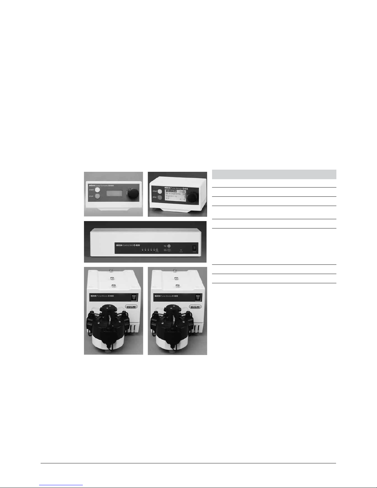
3.1.1 Basic instruments
Table 3-1: Pump Modules
Product Order number
Pump Controller C-610 54111
Pump Manager C-615 54115
Control unit C-620 54110
Pump Module C-601 54101
Pump Module C-605 54105
Page 10
3 Technical data
10
Pump Combinations Operation Manual, Version E
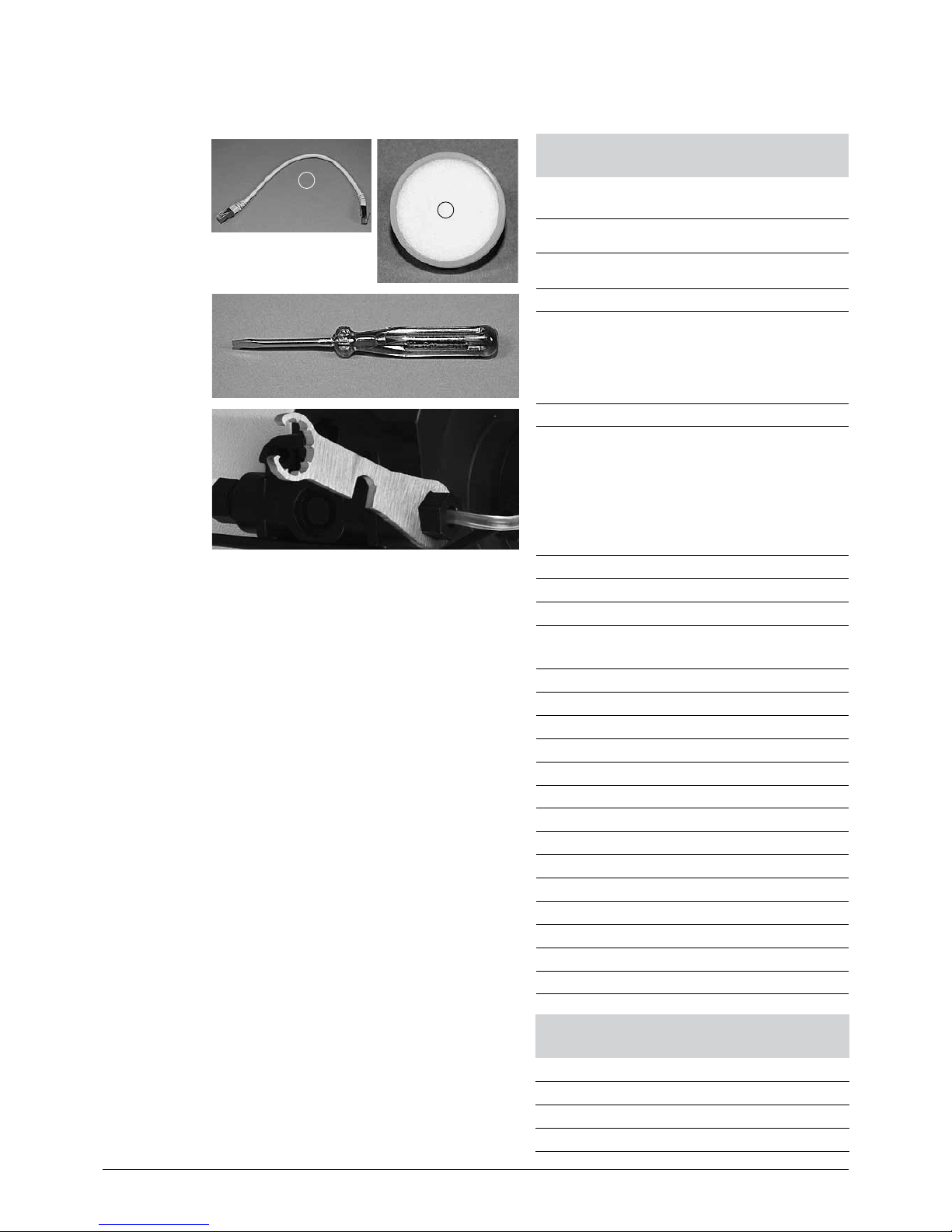
3.1.2 Standard accessories
1
2
Table 3-2: Standard accessories for
Pump Module C-601 and C-605
Product Order
number
a Connection cable RJ45, 0.3 m 44288
b Solvent filter 44340
Screwdriver -
Turix wrench (fits fitting and pipe fitting) 44304
Green fittings and ferrules, 1/8’’ White fittings and ferrules, Ø 4.0 mm -
FEP pressure tubing 1/8’’ x 1/16’’, 1.5 m -
FEP suction tubing 4mm x 2.5mm, length
1.5 m
-
Torx allen wrench TX10 -
Torx allen wrench TX20 -
Regional power cord, 1.5 m:
Type CH 10010
Type Schuko (D,F) 10016
Type GB 17835
Type USA 10020
Type AUS 17836
Operation Manual:
German 96961
English 96962
Spanish 96963
French 96964
Italian 96965
Table 3-3: Standard accessories for
Pump Controller C-610
Product Order number
Green fittings and ferrules -
Overpressure sensor 51110
Torx allen wrench TX6 -
Page 11
3 Technical data
11
Pump Combinations Operation Manual, Version E
Table 3-4: Standard accessories for
Pump Manager C-615
Product Order number
Mixer (pressure sensor with integrated
mixing chamber)
51100
Green fittings and ferrules -
Torx allen wrench TX6 -
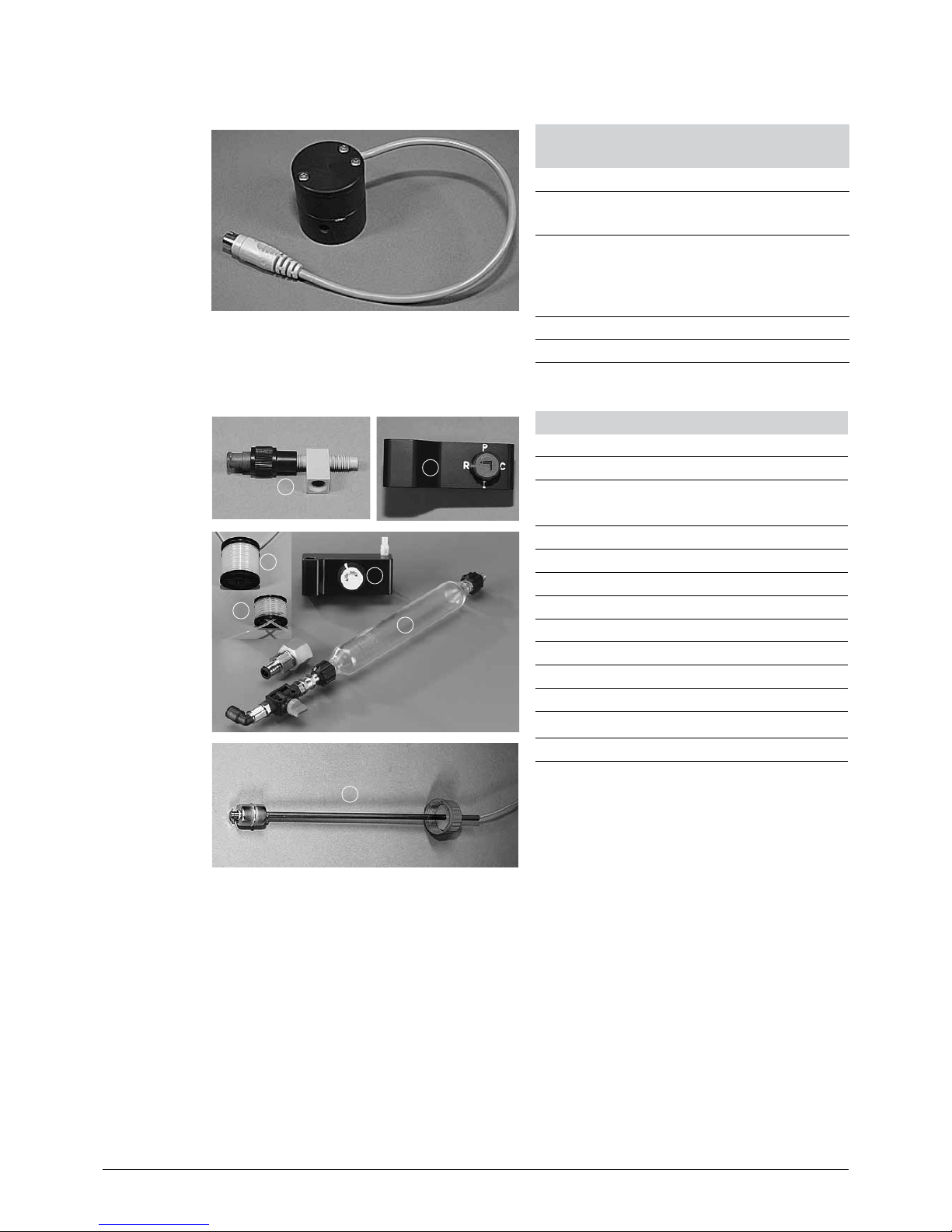
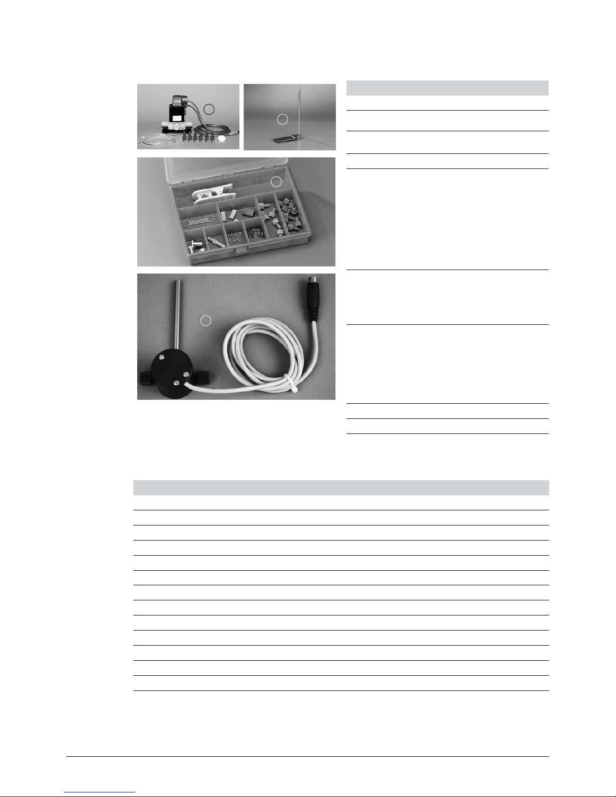
3.1.3 Optional accessories
1
2
Table 3-5: Optional accessories
Product Order number
a Injection valve 44850
b 4-way injection/
purge device
45256
3
6
5
4
c Injection unit, 6/4, complete 44851
d Sample loop 5 ml 45222
e Sample loop 20 ml 44852
f Sample chamber 100 ml 44853
100 ml glass for sample chamber 28193
250 ml glass for sample chamber 54854
500 ml glass for sample chamber 54859
1000 ml glass for sample chamber 54864
7
g Solvent level sensor float type 45285
Page 12
3 Technical data
12
Pump Combinations Operation Manual, Version E
8
9
Table 3-6: Optional accessories
Product Order number
h Solvent valve set 44854
i System stand for pump module 44855
10
j Tubing fitting set 44021
11
k External pressure sensor without
mixing chamber. Needed only for very
pressure sensitive columns, enables
to measure direct at the column inlet.
54040
Glass column, 15/100 / Prep Elut 44030
Glass column, 26/100 / Prep Elut 44035
3.2 Materials used
Table 3-7: Materials used
Component Material designation
Housing (Pump Manager, Pump Controller, Pump Module) PUR foam
Pump excenter housing Aluminium
Housing C-620 Stainless steel
Pump head PEEK
Pump cover PP
Tubings FEP / 1 x silicone
Fitting POM
Valve screw fitting POM
Ferrule ETFE
Cone ring POM
Radial seal PTFE
Pistons Ceramic
Page 13

3 Technical data
13
Pump Combinations Operation Manual, Version E
3.3 Technical data overview
Table 3-8: Technical data of the Pump Controller C-610 and Pump Manager C-615
Pump Controller C-610 Pump Manager C-615
Dimensions ( W x H x D) 150 x 80 x 120 mm 150 x 80 x 120 mm
Weight < 1 kg < 1 kg
Connection voltage 24 V DC 24 V DC
Function Control unit for isocratic separation with
one Pump Module C-601. Simple entry
via selector switch and display of flow
rate on backlit display. With integrated
overpressure sensor to avoid pressure
above 10 bar.
Intelligent control unit for challenging
separating jobs. Simple operation and
programming via the selector switch.
Generously sized, backlit LCD graphic
display. Control of up to two Pump Modules
C-601/605, which enables the simple creation
of precise, binary solvent gradients. Various
inputs and outputs for: 2 valves for the selection of a max. of four solvents, 2 level sensors
for solvent monitoring, 1 pressure sensor
for precise pressure regulation and limiting.
Opportunity to save programs. Automatic
calculation of time and solvent requirement.
Gradient function none With two Pump Modules C-601/605 from
0% – 100% B for total flow rate of
2.5 – 250 ml, linearity ± 2 %.
Display
Illuminated 3 x 7-, segment LCD display
Illuminated LCD display, 128 x 64 pixels
(58 x 29 mm)
Dialog languages none E / G / Sp / F / I / Jp
Interfaces 1x RS- 485 (Systembus)
1x Mini Din (TTL In/Out for alarm
supervision and/or extern. start)
1x RS-232 (process data output)
1x Mini DIN (TTL in/out for alarm supervision
and/or extern. start)
1x Mini DIN (pressure sensor)
2x Mini DIN (optional level sensor)
2x Mini DIN (solvent valves)
Page 14

3 Technical data
14
Pump Combinations Operation Manual, Version E
Table 3-9: Technical data of the Pump Module C-601 and C-605
Dimensions ( W x H x D) 160 x 153 x 305 mm
Weight 4 kg
Connection voltage 100 – 230 VAC ± 15%
Power consumption max. 75 W
Frequency 50/60 Hz
Installation category II
Degree of protection IP20
Pollution degree 2
Environmental conditions
Temperature
Altitude
Humidity
for indoor use only
5 – 40 °C
up to 2000 m
maximum relative humidity 80% for temperatures up to
31 °C, and then linearly decreasing to 50% at 40 °C
Function
Compact, pulsation-poor 3-piston pump. Chemically inert and
biocompatible
Pressure range 0 –10 bar (0 –145 psi) or 0 – 50 bar (0 – 725 psi)
Pump Type Radially arranged 3-piston pump
Flow rate 2,5 ml/min – 250 ml/min
Flow rate accuracy ±2 % of the set flow rate, calibration option for specific
solvents and temperatures
Reproducibility ± 0. 5 % of the set flow rate
Material in contact with solvent PEEK, sapphire, ceramic, FEP, ruby
Pump head Integrated piston backflushing
Page 15

4 Description of function
15
Pump Combinations Operation Manual, Version E
4 Description of function
This chapter explains the basic principle of the Pump Systems and provides a functional description of
the assemblies.
The design of the pump systems enables the delivery of organic as well as aqueous media without
metal contact through a pulsation-poor, 3-piston pump. The modular design of the pump systems
offers various combination options:
Pump system 1:
Pump Controller C-610 and 1 Pump Module C-601
Pump system 2:
Pump Manager C-615 and 1 Pump Module C-601 or C-605
Pump system 3:
Pump Manager C-615 and 2 Pump Modules C-601 or C-605
Pump system 4:
Control Unit C-620 and 2-4 Pump Modules C-601 or C-605
4.1 Functional principle
Pump Controller C-610:
Control unit for isocratic separations with one Pump Module C-601.
Communication with an optional Fraction Collector
C-660.
Simple entry via dial and display of delivery amount on a backlit LCD display.
Pump Manager C-615:
Control unit for one or two pump modules (C-601/605).
Communication with an optional Fraction Collector C-660.
Pressure monitoring.
Control of two optional valves for solvent selection.
Optional level monitoring.
Control Unit C-620:
Control Unit in combination with the software SepacoreControl is able to control your chromatography
system.
Pump Module C-601:
Compact, pulsation-poor, 3-piston pump to a max. of
10 bar, chemically inert and biocompatible.
Pump Module C-605:
Compact, pulsation-poor, 3-piston pump to a max. of
50 bar, chemically inert and biocompatible.
Page 16

4 Description of function
16
Pump Combinations Operation Manual, Version E
The use of two pump modules A and B enables
the formation of a binary gradient. The solvents
enter the pump heads via the suction tubing
(input). The FEP tubing guide the solvents to the
mixing chamber with integrated pressure sensor
and from there via the injection system on to the
column via the pressure tubing (output).
The Pump Manager C-615 regulates the flow
rate of the pump modules A and B and monitors
the current pressure. The maximum pressure
for Pump Module C-601 is 10 bar and for Pump
Module C-605 50 bar. In addition, a variety of
programs and settings enables to select the flow
rate of the solvent, the pressure, time and gradient of the solvents.
Fig. 4.1: Example of System 3
4.2 Operative range of the pump systems
The Pump Module C-601 pumps 2.5 to 250 ml/min of solvent at a maximum pressure of 10 bar. The
Pump Module C-605 pumps 2.5 to 250 ml/min of solvent at a maximum of 50 bar.
ATTENTION
Do not connect the Pump Module C-605 to the Pump Controller C-610, otherwise an error message
appears on the display.
If a Pump Manager C-615 or a Control Unit C-620 is used make sure that the same Pump Modules
C-601 or C-605 are used.
Page 17

5 Putting into operation
17
Pump Combinations Operation Manual, Version E
5 Putting into operation
This chapter describes the installation of the Pump Combination and gives instructions on initial startup.
NOTE
Inspect the instrument for damages during unpacking. If necessary, prepare a status report immediately to inform the postal company, railway company or transport company. Keep the original
packaging for future transport.
5.1 Installation site
Place the instrument on a stable, horizontal surface and consider the maximum product dimensions.
To avoid annoyance caused by bad smells or possible damage to health caused by volatile solutions,
we recommend setting up the Fraction Collector C-660 with an exhaust system. It should thereby be
ascertained that the instrument is not exposed to aggressive substances such as acids, bases and
solvents, which can have a negative influence on the useful life.
WARNING
The pump systems are not explosion proof. Potential explosion risk.
• Never position potential ignition sources near the pump modules.
• Use the pumps in a fume hood or ensure a good ventilation.
5.2 Electrical connections
ATTENTION
Make sure that the voltage on the socket corresponds to the voltage given on the type plate of the
instrument.
Ensure that the instrument is earthed. External connections and extension cables must be provided
with an earthed conductor lead (3-pole couplings, cable or plug equipment) as the mains lead has a
molded plug to avoid risks due to inadvertent defective wiring.
Make sure that no electric sparks form in the instrument or its surroundings as they might damage
the instrument.
An electrostatic discharge can damage the instrument and lead to fire.
NOTE
To cut the power in case of an emergency by unplugging, the instrument or any other item must not
block the mains plug! In this case, the plug must be able to be pulled out instantly.
Page 18

5 Putting into operation
18
Pump Combinations Operation Manual, Version E
5.3 Installation
In order to make things clearer, the following descriptions do not contain the complete names of the
modular pump systems, but rather the general name.
Pump Controller C-610: Pump controller
Pump Manager C-615: Pump manager
Pump Module C-601/605: Pump module
Mixer (pressure sensor with integrated mixing chamber): Pressure sensor
Control Unit C-620: Control unit
5.3.1 Installating the standard accessories
Suction tubing 4 mm x 2.5 mm, length 1.5 m
ATTENTION
The pump module may never be operated without the suction filter, since otherwise impurities may
enter the pump system.
1
2
3
Cut the suction tubing a to the desired length and
fasten it to the suction filter. Place the fitting b and
the ferrule c on the other end of the suction tubing
a. Attach the fitting b and the ferrule c.
Press the suction tubing a and the ferrule c against
a table surface to firmly seal the tubing end with
the ferrule.
Fig. 5.1: Installing fitting and ferrule
2
1
4
Remove the protective foil from the input and output
of the pump head. Screw the white fitting b into the
lower input d of the separator head. Make sure that
all fittings are hand-tight. The end of the tubing a
with the solvent filter goes into the solvent vessel.
Fig. 5.2: Pump head with connected suction tubing
Page 19

5 Putting into operation
19
Pump Combinations Operation Manual, Version E
Pressure tubing 1/8” x 1/16”:
1
5
2
Cut the pressure tubing to the desired length. Attach
the fitting b and the ferrules to one end of the tubing
a as described.
Screw the fitting b into the upper output e of
the separator head. Make sure that all fittings are
hand-tight.
Fig. 5.3: Pump head with connected pressure tubing
5.3.2 Pump system 1: Pump Controller C-610 and 1 Pump Module C-601
NOTE
The Pump Controller C-610 can only be connected to the Pump Module C-601.
1
2
Place the pump module on a level surface. Make
sure the address bus is set to A b. If not, take the
screwdriver and turn the small white dot to A. Connect the power cord a.
Fig. 5.4: Rear connections of the pump module
1
2
3
A holding angle is located in the center at the back
of the pump controller a. Remove it.
There is a rail located at the bottom of the pump
controller a. Slide it from the front to the end of the
stop b on the pump module c.
Attach the holding angle.
Fig. 5.5: Installing the pump controller and the pump module
Page 20

5 Putting into operation
20
Pump Combinations Operation Manual, Version E
1
3
42
Connect the pump module a to the pump controller b via data bus RS-485 by means of the cable
RJ45 d.
c TTL IN/OUT.
Fig. 5.6: Rear connections of pump controller and pump module
The overpressure sensor switches off the pump if the pressure exceeds 10 bar. This maximum pressure of 10 bar cannot be changed. The installation of the overpressure sensor is easy to do and
explained in the following:
Overpressure sensor
Clip the overpressure sensor onto the Pump Module
C-601.
Connect the overpressure sensor to the corresponding connector TTL IN/OUT at the back of the Pump
Controller C-610.
Fig. 5.7: Installing the overpressure sensor
Page 21

5 Putting into operation
21
Pump Combinations Operation Manual, Version E
5.3.3 Pump system 2: Pump Manager C-615 and 1 Pump Module C-601 or C-605
The “or” between 601 and 605 indicates that operation is either possible with Pump Module C-601 up
to 10 bar or with Pump Module C-605 up to 50 bar.
1
2
Place the pump module on a level surface. Connect
the power cord. Make sure that the address selector
switch is set to A a. If not, take the screwdriver and
turn the small white dot to A. Connect the power
cord b.
Fig. 5.8: Rear connections of the pump module
1
2
3
A holding angle is located in the center at the back
of the pump manager a. Remove it.
There is a rail located at the bottom of the pump
manager a. Slide it from the front to the end of the
stop b on the pump module c.
Attach the holding angle.
Fig. 5.9: Installing the pump manager and the pump module
5
7
1
3
4
8
6
2
Connect the pump module a to the pump manager b by means of the cable RJ45 g.
c LEVEL: Port for optional solvent level sensor
d VALVE: Port for optional solvent valve
e PRESSURE: Port for pressure sensor
f TTL IN/OUT
h RS 232
Fig. 5.10: Rear connections of the pump manager and the pump module
Page 22

5 Putting into operation
22
Pump Combinations Operation Manual, Version E
Installation of the mixer
1
2
3
Click the mixer b to the pump module a. Make
sure that all fittings are hand-tight.
Place the mixer cable c on the left side between
pump module and pump manager, and attach it to
the PRESSURE input of the pump manager (position
f in Fig. 5.10).
Fig. 5.11: Pump module with attached mixer
For information on the installation of the standard accessories (suction tubing), please see chapter
5.3.1.
Suction tubing between the lower separator head and the mixer
1
2
Click the fitting and ferrule to the two ends of the
tubing, so that one of the ends is attached to the
output of the separator head a, the other to the
input of the mixer b.
Fig. 5.12: Installing the suction tubing
Page 23

5 Putting into operation
23
Pump Combinations Operation Manual, Version E
Pressure tubing 1/8” x 1/16”:
1
2
Cut the pressure tubing to the desired length. Attach
the fitting and the ferrules to one end of the tubing
as described.
Screw the fitting into the upper output of the
separator head a. Make sure that all fittings are
hand-tight.
Inlet b is only needed if two pump modules are
used. If only one pump module is used it has to be
shut with a blind plug.
Fig. 5.13: Pump head with connected pressure tubing
5.3.4 Pump system 3: Pump Manager C-615 and 2 Pump Modules C-601 or C-605
NOTE
You can connect two pump modules to the pump manager if both modules are of the same type.
5
7
1
3
4
8
6
2
11
11
7
9
10
12
One pump module has the address selector switch
set to A (factory setting), the other has the selector
switch set to B.
Place the first pump module l on a level surface.
Make sure the address selector switch is set to B
j. If not, take the screwdriver and turn the small
white dot to B. Make sure the selector switch of
the second pump module l is set to A i. Place
the pump module on top, and press firmly from the
back, or place it next to the other. Connect both
pump modules to the power supply k.
A holding angle is located in the center back of the
pump manager b. Remove it.
There is a rail located at the bottom of the pump
manager. Slide it from the front to the end of the
stop on the pump module. Attach the holding
angle.
Connect the two pump modules l a to the pump
manager b by means of the cable RJ45 g.
c LEVEL: Port for optional solvent level sensor
d VALVE: Port for optional solvent valve
e PRESSURE: Port for level sensor
f TTL IN/OUT: TTL connection
h RS 232: Serial output signal
Fig. 5.14: Electrical installation
Page 24

5 Putting into operation
24
Pump Combinations Operation Manual, Version E
For the installation of the mixer and the suction tubing, see chapter 5.3.3.
Connection tubing between the separator heads of the pumps:
1
2
The fitting and ferrule are attached to both tubing
ends.
Attach one end of the connection tubing to the input
of the lower separator head a and the other into
the output of the upper separator head b.
1
3
2
Remove the right rear separator head cover a from
the lower pump. Remove the two small nubs on
the inside by pushing them towards the inside and
outside. Now press the connection tubing b into
the slit of the open separator head c and replace
the separator head cover a.
Fig. 5.15: Installing the connection tubing between the separator heads of the pumps
For a description on the installation of the connection tubing between the lower separator head and
the mixer, see chapter 5.3.3.
Page 25

5 Putting into operation
25
Pump Combinations Operation Manual, Version E
Pressure tubing 1/8” x 1/16”:
1
2
3
Cut the pressure tubing to the desired length. Attach
the fitting and the ferrules to one end of the tubing
as described.
Screw the fitting into the upper output of the separator head. Make sure that all fittings are hand-tight.
Between the connections a and b runs the connection tubing between the lower head and the
mixer.
c Outlet mixer mixed solvent
Fig. 5.16: Pump head with connected pressure tubing
5.3.5 Pump system 4: Control Unit C-620 and 2 - 4 Pump Modules C-601 or C-605
For detailed information on this system see the Installation Guide of SepacoreControl.
Page 26

6 Operation
26
Pump Combinations Operation Manual, Version E
6 Operation
This chapter explains the operating elements and possible operating modes. It gives instructions on
how to operate the Pump Combination properly and safely.
ATTENTION
Check the glassware for damages prior to each operation and use only glassware in perfect condition. Glassware with cracks, stars or other damages can fail during operation.
Make sure that all fittings and tubings are hand-tight.
6.1 Pump system 1: Pump Controller C-610 and 1 Pump Module C-601
6.1.1 Controls of the Pump Controller
1
2
3
4
a START button (green): Starts the pump
b STOP button (red): Stops the pump
c Display: Displays the flow rate (in ml/min)
d Dial without press function: Sets the flow rate in
(ml/min)
Fig. 6.1: Control arrangement on the Pump Controller
6.1.2 Operation
Switch on the pump using the power switch at the pump module. The software version appears on
the pump controller display c for approx. 2 seconds. Then it switches to the last flow rate used. In
this mode, the pump is not in operation.
Using the dial d, select the desired flow rate. Values of 2.5 to 250 ml/min are possible.
Press the START button a.
The pump starts and the display c shows the current flow rate in ml/min. A blinking “÷“ - sign indicates that the pump is running. The value can also be changed while the pump is running, using the
dial d. It will be directly implemented, and needs no confirmation. The pump can also be started with
the Fraction Collector C-660 by remote control.
Pressing the STOP button stops the pump.
Page 27

6 Operation
27
Pump Combinations Operation Manual, Version E
6.2 Pump system 2, 3: Pump Manager C-615 and 1 - 2 Pump Modules C-601/605
Pump Manager C-615 can be operated with one or two Pump Modules C-601or one or two Pump
Modules C-605. Since the pump modules only differ with regard to the maximal pressure, they will be
described collectively.
ATTENTION
Note that two Pump Modules of different types must not be mixed.
6.2.1 Controls of the Pump Manager
1
2
4
3
a START button (green): Starts the pump
b STOP/PAUSE key (red): Press once for pause
mode; press again to abort
c Display: Displays parameters and values.
d Selector switch (lockdown switch): Operation of
menu by rotating and pressing.
Fig. 6.2: Control arrangement on the Pump Manager
6.2.2 Display
The display is divided into two areas. The first line (= status line) shows the status of the pump
module; it is fixed. The other lines display the parameters. The left column of the status line shows the
current mode of the pump modules.
There are three possible modes:
Stop: The pump modules are not running.
Pause: The pump modules are pausing. The time display is stopped. The program can be continued
at any time from the point at which it was paused by pressing the START button.
Pumping: The pump modules are pumping according to the set parameters.
The middle column of the status line shows the name of the running program and the number of the
current segment. The latter is not displayed during manual operation. The right column displays the
time. The upper value indicates the remaining time until the end of the program and the lower indicates the remaining time of the current segment.
The bottom lines contain the current parameters of the pump module. The scroll bar on the right
shows where you are within the menu display.
Page 28

6 Operation
28
Pump Combinations Operation Manual, Version E
1 2 3 54
6
a Pump status
b Current segment 01
c Program 01
d Remaining time of current segment
e Remaining time of program
f Manual mode
Fig. 6.3: Overview over the display
NOTE
When the pump system is pumping, parameters highlighted in a dark color can be changed and
selected. Parameters displayed between two black lines cannot be changed anymore (see also
picture above).
Using the selector switch you can navigate through the menu. Turning the selector switcj allows you
to select the desired parameter and pressing it confirms your selection. The cursor jumps to the right,
to the alterable value or, if it is already there, onto the next line (in program mode, it only advances to
stop mode). By turning the selector switch, you can set the desired values. Press the selector switch
to confirm the new value. If no confirmation follows after 10 seconds, the cursor returns to the old
parameter and the left column.
6.2.3 Operation
Switch on the pump using the power switch at the pump module.
The software version appears on the pump controller display for approx. 2 seconds. Then, the Main
menu automatically appears with the last values and parameters used.
The Main menu is identical for manual and programmed operation.
You can scroll through the menu by turning the selector switch.
Select your parameters.
Page 29

6 Operation
29
Pump Combinations Operation Manual, Version E
6.2.4 Systematics of the Menu Mode
Edit Menu
Back
Select
Pres. max.
Flowrate
No. of Segments
Segment No.
Solvent ***
%B *
Time
Save as
Program Menu
Back
Load
Edit
View
Delete
Options Menu
Back
Language
Contrast
Pumpe B
Valves
Pressure Unit
Calibration A
Calibration B
Main Menu
Flowrate
%B *
Press. act
Press. max.
Timer **
Solvent ***
Rest-Vol. A1 ****
Rest-Vol. A2 ****
Rest-Vol. B1 ****
Rest-Vol. B2 ****
Manual control
Show
Programs
Options
Fig. 6.4: Systematics of the Menu Mode
* is only displayed when Pump B is set to Yes within the Options Menu.
** is only displayed in the Manual mode
*** is only displayed when Valves is set to Yes within the Options Menu.
**** is not displayed in the Manual mode if the Timer is set to 00:00:00 (continuous pumping)
Page 30

6 Operation
30
Pump Combinations Operation Manual, Version E
6.2.5 Parameters
Table 6-1: Functions of the Main Menu
Main Menu Description
Flow rate Shows currently set total flow rate of eluent (2.5 – 250 ml).
%B Shows currently set total flow rate of pump B (0 – 100 %).
Press. act. Shows current pressure (0-50 bar) (0 -725 psi).
Press. max. Shows selected maximum pressure.
Timer 00:00:00
(h:min:sec)
If the time limit is zero, the unit is in continuous operation (only in manual operation mode). In
programmed operation mode, no “Timer” line is displayed.
Timer 00:10:00
(h:min:sec)
The unit is in manual mode. It will stop the pump in 10 minutes.
Rest-Vol. A1 Shows the calculated consumption of Eluent A1 until the end of the program.
Rest-Vol. A2 Shows the calculated consumption of Eluent A2 until the end of the program; however, this
line only appears when an optional solvent valve is used.
Rest-Vol. B1 Shows the calculated consumption of Eluent B1 until the end of the program.
Rest-Vol. B2 Shows the calculated consumption of Eluent B2 until the end of the program; however, this
line only appears when an optional solvent valve is used.
Manual Control Switches to Manual mode. %B and maximum pressure can be changed. In addition, a running
program can be interrupted to be continued manually. It is not possible to return to the
program.
Show
This line only appears in programmed operation mode. It causes a jump to the graphic
display of the program progression. It shows an overview of the temporary progression of the
gradient in %B over the entire duration of the program.
Programs
see Program menu
Options
Access to Options menu
Table 6-2: Functions of the Program Menu
Program Menu Description
Back
Back to the Main Menu.
Load The previously defined programs P01 - P10 may be loaded.
Edit Existing programs can be changed or new ones created. If no programs have been stored,
yet “empty” is displayed; otherwise the defined programs P01 - P10 are displayed with all
program parameters. They can be changed.
View If no programs have been saved, yet “empty” is displayed; otherwise the defined programs
P01 - P10 are displayed with all program parameters. They cannot be changed.
Delete If no programs have been saved, yet “empty” is displayed; otherwise the previously defined
programs P01 - P10 can be deleted and confirmed with yes/no. If you have ctubingn Delete
by accident wait for 10 seconds until the cursor jumps to the left.
Page 31

6 Operation
31
Pump Combinations Operation Manual, Version E
Table 6-3: Functions of the Edit Menu
Edit Menu Description
Back
Jumps back to Program Menu.
Select The programs P01 - P10 or “new” can be selected.
Pres. max. Displays the previously set maximum pressure.
Flowrate Shows the current eluent flow rate (2.5 – 250 ml)
No. of Segments Every program can consist of up to 12 segments.
Segment No. Segment numbers can be selected.
Solvent Only when solvent valves are used pump combinations A1/B1, A2/B1, A1/B2, A2/B2 of the
eluents can be selected.
%B Only in the case of two pump modules, start and end point of the mixture ratio of Pump B
(0 – 100 %) can be entered.
Time Time limit in h:min:sec
Save The new program or alterations to existing programs can be saved.
Table 6-4: Functions of the Options Menu
Options Menu Description
Back
Jumps back to Main Menu.
Language The corresponding operating language can be selected.
Contrast Display contrast (0 – 100%)
Pump B When two pump modules are triggered, the address selection switch of one pump module
must be set to A (factory setting) and the other to B.
Valves When solvent valve sets are used, they must be activated here.
Pressure Unit Selection of pressure units MPa, bar or psi (1 MPa corresponds to 10 bar corresponds to
145 psi)
Calibration A Pump A can be calibrated ± 20 %
Calibration B Pump B can be calibrated ± 20 %.
6.2.6 Programming
Fundamentals:
A gradient program is programmed by lining up individual segments.
Each segment is defined by
• an start concentration %B
• a end concentration %B
• one or two pump modules
• valves (if applicable)
• time limit
When solvent valves are used, the pump combinations A1/B1, A2/B1, A1/B2, A2/B2 of the eluents
can be selected.
Start and end concentrations are entered in %B. The time is entered in 00:01:02 (hh:mm:ss). The
starting and end point of the mixture ratio of Pump B (0 – 100%) can only be entered if two pump
modules are used. The increase from the start to the end concentration is linear.
Page 32

6 Operation
32
Pump Combinations Operation Manual, Version E
Anfangskonzentration
Endkonzentration
Dauer
Segment 1
Segment 2
Segment 3
Konzentration B (%)
Zeit t (min)
Concentration B(%)
Segment 1
Segment 2
Segment 3
Start concentration
End concentration
Time t (min)Duration
Fig. 6.5: Systematical gradient
The program number under which the program is to be saved can be selected at will between P 01
and P 10. This option allows an existing program to be loaded, edited and/or viewed and saved under
a new number, whereby the original program remains unchanged.
Creating a new program, example:
Prerequisites:
Two pump modules, e.g. C-605, are installed, each with a solvent. No solvent Valve Set is installed.
A gradient program P02 is created that initially runs for 25 minutes isocratically with pure Eluent A,
then, for 30 minutes, the concentration of Eluent B is continuously increased to 35% and finally this
concentration B is maintained for 20 minutes. Eluent A could e.g. be hexane, and Eluent B ethyl
acetate.
The pressure is 50 bar and the flowrate is 10 ml/min.
255575
100
0
Segment 1
Segment 2
Segment 3
Zeit t (min)
Konzentration B ( %)
Concentration B(%)
Segment 1 Segment 2
Segment 3
100
Time t (min)
0
25
55 75
Fig. 6.6: Systematical gradient, example
To create a new program, the following settings are necessary:
• Pump B is selected: Pump B Yes
• No valve is connected : Valve No
Page 33

6 Operation
33
Pump Combinations Operation Manual, Version E
Table 6-5: Creating a new program in three steps
Step Menu/Confirmation Entry/Confirmation
1 Programs Edit New
2 Select
Pres. max.
Flow rate
No. of Segments
Segment No. (automatic)
% B
Time
Segment No. (automatic)
% B
Time
Segment No. (automatic)
%B
Time
--> Save
New
50 bar
10 ml
3
1
0 - 0
00:25:00
2
0 - 35
00:30:00
3
35 - 35
00:20:00
P02
The program is loaded automatically
3 Show Gradient is shown
NOTE
When your presettings change your programs might make no sense anymore. In this case, redefine
or adapt your programs.
6.3 Pump system 4: Control Unit C-620 and 2,3 or 4 C-601 or C-605
When the Pump Module C-601/605 is used, the address switches must be set to 1 and 2. In case
further Pump Modules C-601/605 are used, the address switches must be set to 3 and 4.
For further information see the Installation Guide of SepacoreControl.
Page 34

6 Operation
34
Pump Combinations Operation Manual, Version E
6.4 Calibration
ATTENTION
Before carrying out the calibration make sure that the system is free of air. Always calibrate the
system under your actual working conditions (flow rate, backpressure, column). After calibration carry
out the measurement again to check the current pump flow rate.
The pump flow rate can be influenced by the following factors:
• The length of the suction tubing.
• The location of the solvent vessel above or below the pump.
• The viscosity of the solvent.
• The backpressure of the chromatography column.
• When using a suction tubing of which the inner diameter is too small.
6.4.1 Calibration of the Pump Controller C-610
Requirements:
For the calibration of Pump Controller C-610 you need a graduated cylinder and a stopwatch.
Set the pump flow rate to 100 ml. Place the suction tubing into the graduated cylinder and start the
pump. After exactly one minute take the tubing out of the cylinder.
If the graduated cylinder contains exactly 100 ml, the pump is calibrated. If too little or too much
solvent is in the cylinder, the pump flow rate is accordingly too low or too high.
If this is the case, recalibrate the pump.
Proceed as follows:
Switch off the pump. Hold the START button pressed while you switch the pump on again. Continue
pressing the START button for another 3 seconds. The display will read “+ C 00”: You are now in
Calibration mode. Increase or decrease the flow rate using the selector switch. Press the STOP button
to confirm the new value.
The pump will now deliver less or more solvent, accordingly. Perform the one-minute measurement of
100 ml again to check the current pump flow rate.
Page 35

6 Operation
35
Pump Combinations Operation Manual, Version E
6.4.2 Calibration of the Pump Manager C-615
Requirements:
To calibrate the Pump Manager C-615 you need a graduated cylinder and a stopwatch.
Set the pump flow rate to 100 ml/min and the time to one minute. Place the pressure tubing into the
graduated cylinder and start the pump. If the cylinder contains exactly 100 ml, the pump is calibrated.
If too little or too much solvent is in the cylinder, the flow rate is too low or too high. If this is the case,
recalibrate the pump.
Proceed as follows:
Select the function Calibration A and Calibration B in the Main Menu > Settings and increase or
decrease the percentage accordingly. Confirm by pressing the selector switch. The pump will now
deliver more or less solvent, accordingly. Repeat the measurement and check the current pump
performance.
If you have changed the pump flow rate during calibration, the correction values for A and B are
displayed on start-up of the Pump Manager.
Fig. 6.7: Correction values displayed at the bottom of the start-up screen
Page 36

7 Maintenance
36
Pump Combinations Operation Manual, Version E
7 Maintenance
This chapter provides instructions on all required maintenance to keep the instrument in good working
condition.
WARNING
All maintenance and repair work requiring the opening or removal of instrument covers and lids must
be carried out by trained personnel and only with the tools provided for this purpose.
WARNING
Electrical hazard:
• Prior to any maintenance work on the instrument switch off the power supply and remove all
sources of flammable vapor.
ATTENTION
Use only genuine consumables and spare parts for any maintenance and repair work in order to
assure continued system performance and reliability. Any modifications to the spare parts used
should only be carried out with the prior written permission of the manufacturer.
7.1 System cleaning
Solvent and sample residue in valves, connections or tubings can greatly impede the performance
of the system as well as greatly endanger your own health, e.g. when replacing a tubing. Thus, it is
essential to flush the entire system with clean solvent.
7.2 Housing
Check the housing for defects (display, controls, plugs) and clean it regularly with a moist cloth.
ATTENTION
Never use solvents as cleaning agents as this may damage the instrument.
7.3 Tube connections
Visually examine the tube connections regularly, if tubes become cracked and brittle replace them with
new ones.
7.4 Sealing system
ATTENTION
When replacing the seals, take care not to damage them.
To prevent damaging the seals never apply grease and never touch them with sharp objects.
7.5 Pressure sensors
• For safety reasons it is recommended to check the mixer and the overpressure sensor from time to
time.
Page 37

7 Maintenance
37
Pump Combinations Operation Manual, Version E
7.5.1 Cleaning the seals
To prolong the lifetime of the seals and in case of unwanted sample contamination (foaming or boiling
retardation) rinse the seals with water or ethanol. Dry the cleaned seals with a soft cloth.
7.5.2 Changing the seals
Visually examine the seals regularly, if seals become cracked and brittle replace them with new ones.
For this purpose, proceed as follows:
1
Remove the pump head cover. Loosen the pump
head screws and remove it. Inside the head, there
is a radial seal a. Remove it.
Fig. 7.1: Removing the radial seal
Attach the new seal to the piston at the pump
housing, and not, as you might expect, to the inside of the pump head, so that the new seal does
not become bent and/or damaged.
Attach the pump head with the flat side first
straight onto the piston, so that the seal is straight;
otherwise it may be damaged. Tighten the screws
uniformly. Place the pump head cover onto the
pump head with the arrow pointing up.
Fig. 7.2: Installing the radial seal
Page 38

7 Maintenance
38
Pump Combinations Operation Manual, Version E
7.6 Piston backrinsing
ATTENTION
When working with aqueous saline solutions, residues might collect behind the piston seal. These
residues must be removed since they can contribute to a faster wearing of the seals.
The system can be rinsed with a spraying device
filled with water. We recommend to use a tissue
at the outlet of the backrinsing to collect the water
drops.
Fig. 7.3: Piston backrinsing with spraying device and tissue
7.7 Changing the valves
Always replace the valves in all pump heads.
For this purpose, proceed as follows:
• Remove the pump head cover.
• Loosen the screws of the pump head and
remove it.
• Using the turix wrench, loosen the valve screw
fittings on the suction and pressure tubing on
the upper and lower side of the pump head.
Fig. 7.4: Uninstalling the fitting
Page 39

7 Maintenance
39
Pump Combinations Operation Manual, Version E
1
2
Fig. 7.5: Installing the new valves
• Remove the valve screw fittings and tubing.
• Remove the valves and insert the new valves.
The inlet valve is marked by one ring a at the
head end, and is attached with that ring facing
the pump head in the direction of the arrow.
The outlet valve is marked by two rings b at
the head end and is inserted into the pump with
the unmarked side first. The valves are positioned loosely in the pump head.
To prevent them from falling out:
• Take the pump head between thumb and index
finger and keep the valve opening shut.
• Hold the pump in a horizontal position.
• Screw the suction tubing onto the inlet valve.
• Screw the pressure tubing onto the outlet valve
and attach the pump head vertically onto the
piston of the pump housing with the arrows
facing upward.
• Screw on the pump head tightly.
• Mount the suction tubing and the pressure
tubing to the distributor with the turix wrench.
• Press the suction tubing into the depression of
the pump head.
• Attach the pump head cover to the pump head.
7.8 Changing the suction and pressure tubing
1
3
2
Fig. 7.6: Installing the connection tubing at the pump
head
To change the suction and pressure tubing, proceed
as follows:
• Using the turix wrench, loosen both valve screw
fittings of the suction and pressure tubing and
pull them out.
• Remove the ferrule, cone ring and valve screw
fittings on all tubing. The ferrule must be
replaced; the cone ring and valve screw fittings
may be reused if they are not damaged.
• Attach the valve screw fitting, with the square
side first, to the ends of the suction and pressure tubings.
• Mount the cone ring and ferrule according to
figure 5.5.
• Proceed as above for the ends of all tubings
that you wish to replace.
• Screw the tubings back into their mountings.
• Tighten the valve screw fitting a using the turix
wrench.
• Press the suction tubing into the depression of
the pump head b, and attach the pump head
cover c to the top.
Page 40

8 Troubleshooting
40
Pump Combinations Operation Manual, Version E
8 Troubleshooting
The following chapter describes how to resume operation of the instrument in the event of any minor
problem. It will list some possible occurrences, their probable cause and suggests how to remedy the
problem. The troubleshooting table below lists possible malfunctions and errors of the instrument and
describes operator enabled courses of action to correct some of tubing problems by him or herself.
The appropriate course of action is listed in the column “Corrective measure”.
The elimination of more complicated malfunctions or errors is usually performed by a BUCHI technical
engineer who has access to the official service manuals. In this case, please refer to your local BUCHI
customer service agent.
In the event of an error, the pump will stop and an acoustic alarm will sound. The acoustic alarm can
be stopped by pressing the START or STOP button once. If the error has been eliminated, the alarm
can be stopped by pressing the START or STOP button twice.
The beeping noise will not sound if the system has been externally stopped by the Fraction Collector
C-660 or the TTL input.
The Pump Module C-610 shows the error message on the display in the form “Exy” whereby “xy”
stands for the error number.
Error “01” of the pump module can either be confirmed with the START or the STOP button. When
the START button is pressed, the error message display disappears, and the pump restarts with the
current value. If the STOP button is pressed, the error message display disappears, and the current
value is shown, as usual. If the flow rate has still not been achieved, error “01” will be displayed again.
If the waste container is full or the connected Fraction Collector C-660 shows an error, the pump
will stop without displaying an error. The error message will be displayed on the fraction collector.
The pump cannot be switched on again until the cause has been eliminated and the error has been
confirmed at the fraction collector.
8.1 Malfunctions and their remedy
Table 8-1: Error messages of the Pump Controller C-610
Error number Possible cause Remedy
01 Pump cannot reach desired flow rate. The
pump electronics have switched off the pump,
since the pressure is too high.
Control backpressure
Contact the BUCHI Customer Service.
02 No connection to pump (timeout). Check RJ 485 connections. Check main power.
Check switch + connections. Check selector
switch at the back side of pump module.
03 Check sum false or unintelligible response
from pump.
Contact the BUCHI customer service
04 Error while writing in the pump electronics
EEPROM.
Contact the BUCHI customer service
05 Temperature of pump electronics too high. Contact the BUCHI customer service
06 Line voltage too high. Contact the BUCHI customer service
07 Line voltage too low. Contact the BUCHI customer service
Page 41

8 Troubleshooting
41
Pump Combinations Operation Manual, Version E
Table 8-1: Error messages of the Pump Controller C-610 (cont.)
Error number Possible cause Remedy
08 Invalid data in pump electronics EEPROM. Contact the BUCHI customer service
09 RS-485 bus voltage too low. Contact the BUCHI customer service
10 Internal auxiliary voltage not within tolerance
of pump electronics.
Contact the BUCHI customer service
11 Pump electronics fan defective. Contact the BUCHI customer service
23 EEPROM C-605. Contact the BUCHI customer service
25 Transfer error to RS485. Contact the BUCHI customer service
31 The wrong pump is connected (C-605 instead
of C-601).
Replace C-601 with C-605.
Table 8-2: Error messages of the Pump Manager C-615
Error number Possible cause Remedy
01 Pump A: Flow rate out of tolerance. Control backpressure
Contact the BUCHI customer service
02 No answer from Pump A. Check RJ 485 connections.
Check main power.
Check switch + connections.
Check selector switch at the back side of the
pump module.
03, 14, 25 Communication failure on RS485. Contact the BUCHI customer service
04 EEPROM pump A. Contact the BUCHI customer service
05 Pump A: Temperature out of tolerance. Contact the BUCHI customer service
06 Pump A: Main voltage above tolerance. Contact the BUCHI customer service
07 Pump A: Main voltage below tolerance. Contact the BUCHI customer service
08 Pump A: Invalid data in memory. Contact the BUCHI customer service
09, 10 Failure in pump A. Contact the BUCHI customer service
11 Cooling fan in Pump A not working. Contact the BUCHI customer service
12 Pump B: Flow rate out of tolerance. Contact the BUCHI customer service
13 No answer from Pump B. Check RJ 485 connections.
Check main power.
Check switch + connections.
Check selector switch at the back side of pump
module.
15 EEPROM pump B. Contact the BUCHI customer service
16 Pump B: Temperature out of tolerance. Contact the BUCHI customer service
17 Pump B: Main voltage above tolerance. Contact the BUCHI customer service
18 Pump B: Main volatage below tolerance. Contact the BUCHI customer service
19 Pump B: Invalid data in memory. Contact the BUCHI customer service
20, 21 Failure in pump B. Contact the BUCHI customer service
Page 42

8 Troubleshooting
42
Pump Combinations Operation Manual, Version E
Table 8-2: Error messages of the Pump Manager C-615 (cont.)
Error number Possible cause Remedy
22 Cooling fan in pump B not working. Contact Customer Service.
23, 24 EEPROM C-615. Contact Customer Service.
26 Pressure higher than max. pressure settings. Lower the flowrate, if possible, increase the max.
pressure
27 Unexpected restart. Restart.
28 Check solvent level A. Refill solvent bottle A.
Check level sensor position.
Check level sensor adjustment.
29 Check solvent level B. Refill solvent bottle B.
Check level sensor position.
Check level sensor adjustment.
30 No pressure sensor connected. Check connection; otherwise, contact the BUCHI
customer service
8.2 Pulsation of a pump module
A repeated strong pulsation of the pumps suggests that the opening or closing times of the inlet or
outlet valves are not correct.
Possible causes:
Improper use:
• The solvent filter is not used. When the filter is not used, particles, dust and fibers can enter the
valves and affect their functionality.
• The sample mixture is introduced to the separating column with the pumps. The pumps are exclusively designed to pump solvents.
Using technical solvents:
Technical solvents are normally not free of polar residues. Especially during extended standstill periods
these residues can adhere to the polar surface of the sapphire valve seat or the ruby valve ball and
influence the closing speed. In the worst case the valve can jam.
Possible sealing abrasion in the outlet valve
Each sealing is subject to a permanent abrasion during its service life. This abrasion is especially high
at the beginning during the so-called running in phase of the sealing. For small flow rates the flow
speed within the valve might be too low for a self-purification of the valves. For continuous flow rates
of under 10 ml/min we recommend to rinse the pumps at least once a week according to the procedure described below.
Solving the problem:
• Rinsing the pump module:
– Disconnect the pressure tubing between the pressure sensor and the injection system, so that
the rinsing solution does not contaminate the separating column.
– Rinse the pump module with a high flow rate with ethanol or chloroform ( >150 ml /min for two
minutes).
ATTENTION
Do not pump the solvent round in circles. The solvent may only be reused after distillation.
Page 43

8 Troubleshooting
43
Pump Combinations Operation Manual, Version E
When the measures above are not successful, continue as follows:
• Localizing the defective valve:
– Let the pump module run with low flow rate (10 ml/min) and pull the suction tube out of the
solvent bottle for a short time (about 1 second).
– Observe, at which of the three suction tubes the air bubble does not disappear after 1 minute.
– Switch off the pump.
– Dismount the inlet valve. Make sure that the thin PTFE sealing does not get lost.
– Blow out the valve with compressed air.
– Remount the inlet valve.
– Let the pump run again.
– Blow out the valve with compressed air
If this procedure is not successful:
– Dismount the inlet valve again and make sure that the thin PTFE sealing does not get lost.
– Rinse it with solvents, e.g. aceton.
– Remount the inlet valve.
– Let the pump run again.
If this procedure is not successful:
– Dismount the inlet valve and exchange it with a new one.
– Let the pump run again.
Now the inlet valves should function properly. Restart the pump. It should also function properly now.
If not, carry out the same procedure for the outlet valves as carried out for the inlet valves. Thereby
always consider the thin PTFE sealing.
After all valves have been checked successfully the pump operates correctly. If all attempts to eliminate pulsating flow rates fail, contact the BUCHI Customer Service.
8.3 Customer service
Only authorised service personnel are allowed to perform repair work on the instrument. These
persons have comprehensive technical training and knowledge of possible dangers which might arise
from the instrument.
Contacts for official BUCHI customer service offices are given on the BUCHI website at: www.buchi.
com. If malfunctions occur on your instrument or you have technical questions or application problems, please contact one of these offices.
The customer service offers the following:
• Spare part delivery
• Repairs
• Technical advice
Before calling us
Our service personnel will be able to service you more efficiently if you have the following information:
• The serial number and the model number of the instruments involved
• The installation procedure that you used
• A list of concise symptoms
• A list of operating procedures and conditions that you were using when the problem arose
• A list of other devices connected to the system and a description of those connections
• A list of other electrical connections on the same circuit in the room
Page 44

9 Shutdown, storage, transport and disposal
44
Pump Combinations Operation Manual, Version E
9 Shutdown, storage, transport and disposal
This chapter instructs on how to shut down the instrument, how to pack it for storage or transport and
specifies the storage and shipping conditions.
9.1 Storage and transport
WARNING
Biohazard:
• Remove all dangerous substances from the instrument and clean it thoroughly by flushing it with
dry air or nitrogen.
Store and transport the instrument in its original packaging.
WARNING
Electrical hazard:
• Always remove mains lead from the socket first to avoid having live cables in the laboratory.
9.2 Disposal
To dispose of the instrument in an environmentally friendly manner a list of materials is given in chapter
3, please ensure that the components are separated and recycled correctly. Please follow current
regional and local laws concerning disposal.
Page 45

10 Spare parts
45
Pump Combinations Operation Manual, Version E
10 Spare parts
This chapter lists spare parts, accessories, and optional extras, including all of the relevant order
information for ordering from BUCHI. Always state the product designation and part number when
ordering any spare parts.
Use only genuine BUCHI consumables and spare parts for maintenance and repair to ensure optimum
system performance and reliability. Prior written permission of the manufacturer should be obtained
before any modifications are made to the spare parts used.
1
2
Table 10-1: Spare parts
Product Order number
a Connection cable RJ45, 0.3 m 44288
b Solvent filter 44340
25 fittings, 1/8’ green 40961
25 ferrules, 1/8’’, green 40956
25 fittings, Ø 4.0, white 54044
5 ferrules, Ø 4.0, white 54056
Turix wrench (fits fitting and pipe fitting) 44304
Set of suction tubings/pressure tubings,
complete
51905
Torx set TX6, TX10, TX20, TX30 45271
Page 46

10 Spare parts
46
Pump Combinations Operation Manual, Version E
5
Table 10-1: Spare parts (cont.)
Product Order number
e Mixer (pressure sensor with inte-
grated mixing chamber)
51100
Overpressure sensor 51110
FEP pressure tubing 1/8’’ x 1/16’’,
length 5 m
44354
FEP suction tubing 4mm x 2.5 mm,
lenght 5 m
54059
Page 47

11 Declarations and requirements
47
Pump Combinations Operation Manual, Version E
11 Declarations and requirements
11.1 FCC requirements (for USA and Canada)
English:
This equipment has been tested and found to comply with the limits for a Class A digital device,
pursuant to both Part 15 of the FCC Rules and the radio interference regulations of the Canadian
Department of Communications. These limits are designed to provide reasonable protection against
harmful interference when the equipment is operated in a commercial environment.
This equipment generates, uses and can radiate radio frequency energy and, if not installed and used
in accordance with the instruction manual, may cause harmful interference to radio communications.
Operation of this equipment in a residential area is likely to cause harmful interference in which case
the user will be required to correct the interference at his own expense.
Français:
Cet appareil a été testé et s'est avéré conforme aux limites prévues pour les appareils numériques
de classe A et à la partie 15 des réglementations FCC ainsi qu’à la réglementation des interférences
radio du Canadian Department of Communications. Ces limites sont destinées à fournir une protection adéquate contre les interférences néfastes lorsque l’appareil est utilisé dans un environnement
commercial.
Cet appareil génère, utilise et peut irradier une énergie à fréquence radioélectrique, il est en outre
susceptible d’engendrer des interférences avec les communications radio, s’il n’est pas installé et
utilisé conformément aux instructions du mode d’emploi. L’utilisation de cet appareil dans les zones
résidentielles peut causer des interférences néfastes, auquel cas l’exploitant sera amené à prendre les
dispositions utiles pour palier aux interférences à ses propres frais.
Page 48

11 Declarations and requirements
48
Pump Combinations Operation Manual, Version E
11.2 Declaration of conformity
Page 49

Page 50

BÜCHI Labortechnik AG
CH-9230
Flawil 1 / Switzer land
T +41 71 394 63 63
F +41 71 394 65 65
www.buchi.com Quality in your hands
 Loading...