

Page 1

Operation Manual
Glass Oven
B�585
096981
en
Page 2

Page 3

Glass Oven B-585
Contents
Contents
1 Scope of delivery 2
1.1 Glass oven for drying 2
1.2 Glass oven for ball tube (Kugelrohr) distillation 3
2 Safety 5
2.1 Symbols 5
2.2 Requirements to be met by the customer 5
2.3 Proper use 5
2.4 Improper use 6
2.5 General hazards 6
2.6 Safety measures 7
2.7 Over-temperature protection 7
3 Function 8
3.1 Working with the glass ovens 8
4 Putting into operation 10
4.1 Installation location 10
4.2 Power connections 10
4.3 Installation of the glass parts and
the drive unit 10
5 Operation 11
5.1 Overview program structure 11
5.2 Basic display arrangement 12
5.3 Operation of the B-585 Drying 16
5.4 Operation of the B-585 Kugelrohr 19
5.5 Accessories: Sublimation and freeze drying 22
5.6 Converting the Glass Oven configurations 23
6 Maintenance 26
6.1 Cleaning 26
6.2 Service 26
6.3 Customer service 26
7 Taking out of operation 27
7.1 Storage / Transport 27
7.2 Disposal 27
8 Replacement parts 28
8.1 B-585 Drying configuration replacement parts 28
8.2 B-585 Kugelrohr configuration
replacement parts 29
8.3 Sublimation accessory replacement parts 29
9 Appendix 30
9.1 Technical data 30
9.2 Error massages 30
9.3 Materials used 31
9.4 Declaration of conformance 32
Please read these instructions thoroughly before using the Glass
Oven B-585. Keep these instructions in the imme diate vicinity
of the device so that they can be referred to at any time.
Chapter 2 contains important safety advice. These infor mation
is vital to the safe operation of the glass oven.
The right to make technical changes without notice is re served. No portion of these instructions may be repro du ced in
any man ner, nor may it be edited, copied or distri buted using
any electro nic or optical systems without the expres sed written
consent of Büchi Labortechnik AG.
All rights reserved.
Copyright © Büchi Labortechnik AG, 2004
EN Version G
as of Software-Version 1.1 (32 pages) Order Code
B-585 Instructions 096981
1
Page 4

Glass Oven B-585
1 Scope of delivery
1 Scope of delivery
1.1 Glass oven for drying
Description
B-585 Drying Order Code
Drying oven B-585
100 V - 230 V / 50/60 Hz 46600
Additional package contents:
Fig. 1: B-585 Drying
2 Replacement fuses 3,15 AT
1 Drying accessory complete 37010
1 Mains cable PNE, 1.5m
Typ CH 10010
Typ Schuko 10016
Typ GB 17835
Typ USA 10023
Typ AUS 17836
Fig. 2: Ball tube drive complete
1 Instructions
German 96980
English 96981
French 96982
Italian 96983
Spanish 96984
Optional accessories
1 Complete ball tube drive for con verting to a ball tube distillation oven 46617
(Kugelrohr) incl. cooling device
1 Complete sublimation accessory for
conversion to the Sublimation configuration 37133
1 Communication cable 46728
B-585 / V-500
Fig. 3: Sublimation accessory complete
2
Page 5

Glass Oven B-585
Fig. 4: B-585 Kugelrohr configuration
1 Scope of delivery
1.2 Glass oven for ball tube (Kugelrohr) distillation
Description
B-585 Kugelrohr configuration Order Code
Kugelrohr destillations oven B-585
100 V - 230 V / 50/60 Hz 46601
d
Fig. 5a: Glass Accessories including with B-585 Kugelrohr configuration
a
b
Additional package contents:
1 30 ml rotation drying flask with
vapour duct and clip a 37143
1 20 ml ball tube with vapour duct and
clips b 37107
1 Replacement gasket for the ball tube
drive d 37288
1 60 g tube of vacuum grease 48197
2 Replacement fuses 3,15 AT
2 GL 14 hose nipples 37287
1 Iris diaphragm cpl. e 46605
1 Cooling unit compl. c 46616
1 3-wire power cord. 1.5m
Type CH 10010
Type Schuko 10016
Type GB 17835
Type USA 10023
Type AUS 17836
1 Instructions
German 96980
English 96981
French 96982
Italian 96983
Spanish 96984
e
Fig. 5b/c: Other Accessories including with B-585 Kugelrohr configuration
c
3
Page 6

Glass Oven B-585
1 Scope of delivery
Optional accessories
1 10 ml ball tube
with vapour duct and clips 37118
1 40 ml ball tube
with vapour duct and clips 37117
1 Drying accessory for converting to the
Fig. 6a: 10 ml ball tube
B-585 Drying model 37010
1 Complete sublimation accessory for
converting to the B-585 Sublimation model 37133
1 Freeze drying accessories 46710
Fig. 6b: 40 ml ball tube
Fig. 6c: Drying accessory
Fig. 6d: Complete sublimation accessory
Fig. 6e: The freeze drying accessory
4
Page 7

Glass Oven B-585
2 Safety
2 Safety
The device has been built using state art techniques and in accordance with the recognized safety regulations. There are no
risks or hazards associated with the use of this device if used
according to the instructions.
2.1 Symbols
Stop
Information about hazards which can lead to serious material
damage or cause serious or potentially fatal injury.
Warning
Information about hazards which can be harmful to your health
and lead to material damage.
Please note
Information about technical requirements. Non-obser vance can
lead to malfunctions, inefficiency and lost production.
2.2 Requirements to be met by the customer
The device may only be used by laboratory personnel and other
persons who, due to their training or experience, can recognize
the hazards associated with operating the device.
Personnel without this type of training or persons currently in
training require careful instruction. This instruction can be considered to be the basis for this instruction manual.
When working with solvents whose composition is not known,
it is the management’s responsibility to obtain information from
the appropriate persons about possible hazards associated with
using such solvents.
2.3 Proper use
The device has been designed and built as a laboratory device.
Appropriate uses of the device are for the drying, distillation,
sublimation and freeze-drying of small quantities of substance
from room temperature up to 300°C.
5
Page 8

Glass Oven B-585
2 Safety 7Glass Oven B-585
2.4 Improper use
Using the device for any other purpose other than those stated
above or using in any application that does not correspond to
the technical data is considered to be improper usage.
Any damage resulting from such use is the sole responsibility
of the operator.
Using the device in the following situations is especially prohibi ted:
• Using the device in rooms which require explosion-proof
equipment.
• Testingsampleswhich,throughimpact,friction,heatorspar-
king, may explode or ignite (for example, explosives, etc.).
• Usinginconjunctionwithsolventscontainingperoxides
2.5 General hazards
General hazards arise from:
• Whenusingwithmixtureswithunknowncompositionorim-
puri ties.
• Flammablesolvents(attendtheburningpoint)
• Toxicgases,whichcanresultduringoperation.
• Flammablegasesorsolventfumesinoraroundthedevice.
• Damagedglassware.
• When the device is too close to the wall (see Chapter 4,
Putting into operation)
• Touchingtheheatingelements,causingburns.
• Squeezingsbyinappropriateretractingandextendingofthe
drive or adjustment of the heating angle.
• Storageoftheunitinconnedplaceswhenhot.
Rotation drive
Care must be taken to ensure that hair, clothing, jewelry or any
other article is prevented from entering any rotating parts of
the instrument.
Removing the cover using common hand tools is - except for
authorized maintenance personnel, prohibited. The device may
not be put into operation if the glassware is damaged.
It may be fatal if any high voltage parts of the device are touched!
Use of dry ice
Dry ice can cause serious burns if allowed to come into contact
with skin or eyes. Appropriate protective clothing must be worn.
NB Dry ice will foam strongly if allowed to come into contact
with acetone.
6
Page 9

2 Safety
2.6 Safety measures
It is required that you wear protective gear such as pro tective
glasses, gloves and a lab coat.
These instructions must be available at all times to the operating
personnel at the location where the device has been installed,
as it is considered to be a component of the glass oven. This
is al so true of the copies of the in s tructions in other languages,
which may be ordered separately at a later date.
Modifications
Modifications to the device or to the replacement parts or acces sories, as well as using any replacement parts or acces sories
ot her than those mentioned in these in struc tions, is only allo wed
with the express written consent of Büchi Labortechnik AG.
Responsibilities of the Management
The management is responsible for instructing its per son nel. To
help in this task, you can order these instructions in several
other languages.
Protective Shield
The protective shield mounted on the device does not serve to
completely protect the operator from coming into contact with
hot glass elements. It is only there to protect the operator from
burns occurring due to carelessness.
2.7 Over-temperature protection
The device has an over-temperature cut-out for the protection
of samples and the oven. This protective device switches the
heating off in the event of the oven temperature reaching 320°C:
•Foradditionalinformation,pleasesee.
Troubleshooting; Chapter 9.2 Error messages
Page 10

Glass Oven B-585
3 Function
3 Function
3.1 Working with the glass ovens
The core of the glass oven comprises two borosilicate glass
tubes lying one within the other. The outer tube (1) protects
against damage to the heating tube, and at the same time
prevents contact with parts that are electrically live. A metal
screen (2) around the outer jacket provides additional protection. The transparent, electrically conductive semi-conductor
coating, does the actual heating. Temperatures up to 300°C
are attained, the oven temperature being monitored via an
integral temperature sensor (4). A lock nut (5) can be used
to tilt the oven and to secure it in a suitable position.
The basic equipment can be used for drying,
distilling and sublimating, if the appropriate accessories are used.
To avoid thermal damage to, or decomposition of, samples
requires gentle heating techniques. Conventionally, this has
been done by heating the sample via an intermediate medium
(e.g. water or oil) whose temperature is regulated just above
the required setpoint for the sample. In bulb-tube distillations,
a semi-conductor coating is used to provide direct, yet still
gentle, heating. The product may be heated directly because
the heat source provides evenly across the entire surface
of the heater. Because the thermal capacity and the thermal
conductivity of the vapour-coated glass are significantly better than those of the gas/atmosphere outside, most of the
heat given off is taken up by the glass and radiated inwards.
There are further advantages in addition to the gentle heating:
Because 75% of the heat is supplied to the product through
radiation and only 25% via heated gas, the oven heats up
very quickly and also cools down relatively quickly when it is
switched off. In addition, because the semi-conductor is fully
transparent, the sample can be observed during the drying
process, so that any decomposition can be identified quickly
and any necessary countermeasures can be taken in time.
8
Page 11

Glass Oven B-585
a
b
3 Function
c
d
Fig. 7: Function principle of the glass oven
a Jacket tube
b Heat protection
c Heating tube
d Temperature sensor
The electrically conductive semiconductor layer operates at
supply voltage. There is a possibility for fatal injuries when the
outer jacket tube has been removed.
9
Page 12

4 Putting into operation
Glass Oven B-585
4 Putting into operation
Please inspect the package for any damage while un packing.
Any damage suspected of having occur red during transportation
should be reported imme diately to the appropriate authorities
(ditributor, post office, railroad or trucking company).
The original packaging should be saved in case it is required
at a later date.
4.1 Installation Location
The device must be set up on a clean, stable and level surface.
The device may not be used in rooms meant for use with explosive gases.
For safety reasons, there must be at least 30 cm between
the wall or other equipment and the rear and sides of the device.
No containers, chemicals or other devices should be placed
behind the device.
4.2 Power connections
Check to ensure that the voltage coming out of the electrical
socket agrees with the voltage stated on the devices ratings
plate. The glass oven must always be connected to an earthed
electrical socket. External couplings and extension cords must
have an earth wire (3-pole couplings, cords and sockets). It is
prohibited to cut or interrupt the earth wire. to avoid the risk of
damage to the device, or personal injury.
In a vertical operation care must be taken to ensure that every
cable of the B-585 not gets in contact with the heating element.
Discription of the interface:
Drive:
Vac Pump:
B-585/V-500 to a vacuum pump V-500
Air Pump:
Method (not availlabel at Büchi)
4.3 Installation of the glass parts and
the drive unit
interface for the drive unit
interface for communications cable
interface for air pump Mettler for the KF-
10
For installation of the different parts please see chapter 5.6
"Converting the Glass Oven".
Page 13

Glass Oven B-585
5 Operation
5 Operation
5.1 Overview of program structure
WORKING DISPLAY
MODE
- program
- manual
VACUUM CONTROL
Yes / No
PROGRAMS
- load
- view
- edit
- delete
UNIT OF TEMPERATURE
°C / ° F
CONTRAST
0 - 100%
OPTIONS
LANGUAGE
- English
- Spanish
- German
- Italian
- French
- Japanese
Fig. 8: Overview of program structure B-585
11
Page 14
Glass Oven B-5855 Operation
a)
h
e
b
c
a
g
f
d
i
j
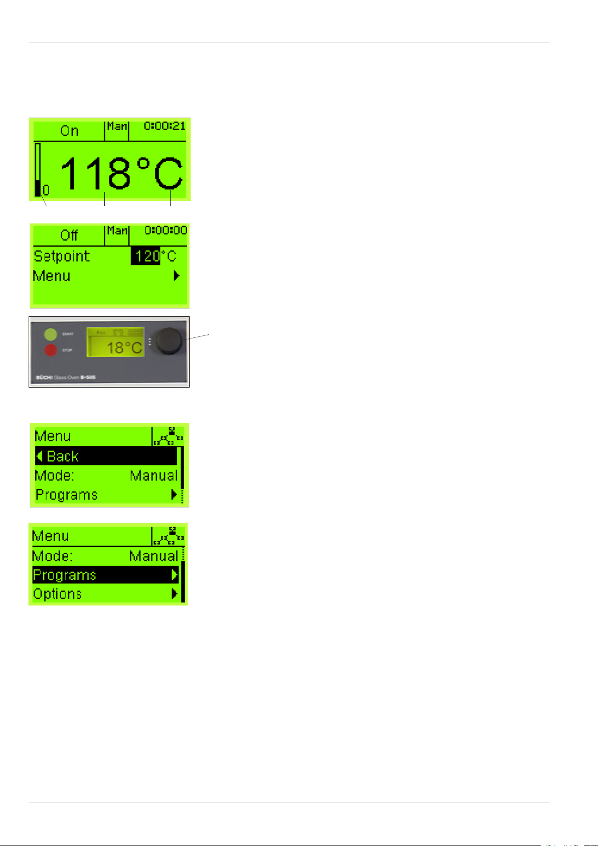
5.2. Basic display arrangement
a Active mode information
b
Operating condition
c
Actual temperature
d
Temperature unit of measurement
e
Graphic display of heating intensity
f
Display of the elapsed time
g
Set point adjustment
h Menu adjustment
i Graphical display, shows level indication of the user
j
Multifunction button
By pressing and turning the Multifunction botton allows
access to the working menu where changes and modifications can be made. Pressing the Multifunction botton again
activates the set point. An existing value can be modified
by turning the Multifunction botton and is stored by pressing the botton again. The cursor will jump forward to the
display menu.
By turning the Multifunction botton you get back
to the actual working menu or access another
control mode. It is possible to change/create,
delete, read or load a program profile in the menu
program or change the main settings.
12
Page 15

Glass Oven B-585
5 Operation
5.2.1 Operation of the B-585 in manual mode
Cchanging the actual temperature and the speed
of rotation in manual mode.
By pressing the Multifunction botton the user gets into the
working menu, where the changes to the actual temperature
set point and the rotation speed can be made. Pressing the
Multifunction botton again activates the menu set point. To
select the desired temperature turn the button. By pressing
the Multifunction botton the selected temperature will be
stored. The cursor will then jump forwards to the rotation
speed or (if no rotation speed is available) to the menu.
5.2.2 Selection of the rotation speed before
operation
The rotation speed can be pre-selected prior to a run with
real samples. Select ”speed of rotation” from the working
menu and confirm the desired value by rotating and then
pressing the Multifunction button.
The motor will now start running at the newly adjusted speed.
Note, if the new chosen speed is not confirmed within 10
seconds, then the value automatically reverts to the previously stored value. Pushing the ”stop” button causes the
motor to stop.
5.2.3 Change/build or delete a program profile
in manual working mode.
Even when the instrument is working in manual mode , a
program can be created, deleted or changed.
Whilst the instrument is in operation, the program points to
”load program” and ”mode of operation” can not be chosen.
13
Page 16

5 Operation
Glass Oven B-585
5.2.4 General information about the menu
functions:
On the menu item language it is possible to choose between
the following languages: English, Spanish, Italian, French,
German and Japanese.
On the menu item contrast it is possible to optimize the
display.
On the menu item temperature it is possible to choose either
Fahrenheit or °Celsius.
On the menu item Vac. pump it is possible to switch the
vacuum pump on or off directly from the B-585, (Requires
Büchi vacuum pump V-500 series with the B-585/V-500
cable). The cable has to be connected at the plug socket
in the middle.
Fig. 9: Angle 3
5.2.5 Adjusting the working angle of the oven
The working angle of the oven can be adjusted by the release handle.
Fig. 10: Working angle
14
5.2.6 Working at room temperature
To operate at room temperature, select the value ”RT”
from the Setpoint values. This setting switches the heating
circuitry off.
Page 17

Glass Oven B-585
b
e
c
a
d
f
g
5 Operation
5.2.7 Operation of the B-585 in the program mode
Fundamental arrangement of the display:
a
Information about the active mode and current stage of
the program (I, II or III)
b
Operating condition
c
Actual temperature
d
Temperature unit of measurement
e
Graphical heating display
f
Indication of the remaining time to the end of the program
g
Indication of the remaining time in the current program
step
Program load, edit select, delete, view:
By turning the Multifunction button, the display will change to
the working menu. By choosing the menu ”program” existing
programs can be checked, deleted or modified.
To load an existing program, turn the Multifunction button to
load and confirm it by pressing the button. The cursor will
jump to the next selection. By turning the buton again the
stored programs are shown (P01, P02...) . By pressing the
button, the chosen program will be confirmed. Now it shows
the working display. To start the chosen program press the
green button start.
5.2.8 Change or create a program:
If the cursor is on position change/new, a new program can
be built or an existing program can be changed.
By confirming choose the cursor will get to the existing pro-
grams. (P01, P03, new.....).
After choosing the program the cursor jumps to step1. Pressing the Multifunction button allows the user to change the
temperature or time. The cursor jumps to the temperature
display. It is now possible to make any desired changes.
Press the button to enter the chosen temperature and the
cursor will then jump to the time display. Continue accordingly as for the temperature setting.
If a new program is created, an empty memory positions
are will be offered. If all of the 10 memory position
occupied, then an existing program must be either
edited and saved to store the desired parameters,
or one must be deleted before a new program can
be created and stored.
At any time, even during a run, any program stored in memory (apart from the one currently loaded), can be edited or
deleted. New programs can also be created.
15
Page 18

Glass Oven B-585
5 Operation
5.3 Operation of the B-585 Drying Oven
Please ensure that the device has been correctly put into operation according to Chapter 4, Putting into operation.
5.3.1 Operational and display elements
a
k
i
j
Fig. 11: B-585 Drying
e
c
d
h
f
g
b
a
Unit sockets with main fuses
b
Main power switch
c
Digital display showing the current temperature
d
Multifunction botton for setting the desired oven
tempe rature
e
Pilot lamp, illuminated when heating is turned on
f
Lever used to open the iris diaphragm
g
Glass ball cooling apparatus
h
Holder for the save contact of the furnace
i Start
j Stop
k Lever of the adjustment of the inclination of the furnace
angel
r
16
5.3.2 Drying
The glass oven can also be used to dry solid substances.
Unlike permanently installed drying cabinets, the drying oven
only has to heat up a small volume. It requires less energy,
reaches the desired temperature more quickly, and thereby
reduces the time for drying. Moreover, if used as a vacuum
oven, it has a significantly tighter seal than a drying cabinet
and can therefore maintain a better vacuum. There are three
methods used for drying direct drying, indirect drying, and
rotary drying. The drying accessory is used for direct and
indirect drying, the rotary flask for rotary drying.
Page 19

Glass Oven B-585
5 Operation
a
Fig. 12: Direct Drying A
ed
c
5.3.3 Filling with the Material to be Dried
The drying accessory consists of three parts. While the drying
is in progress, the drying tube a into which the product is
put (either directly or inside a container), is in the oven. The
end cap b that catches the moisture evaporated off can be
b
filled with desiccants to improve the drying effect. A stopcock c is used to evacuate or aerate the sample chamber.
The aluminum flange ring d joins the two glass sections
in a screwed joint, sealing them vacuum-tight. The flange
ring e is also used to hold the drying accessory in position
within the glass oven. This drying accessory does not rotate.
The material to be dried can be placed in the drying tube in various ways. The method chosen depends mainly on the amount
of substance.
Example A
A large quantity of the material to be dried is placed directly in
the drying tube. With this method, existing glass boats, metal
dishes, etc., may be used. This drying method should not be
used for hygroscopic samples, as these may absorb moisture
during transfer to another container after having been dried.
Fig. 14: Rotation Drying Flask C
Example B
The material to be dried is placed in its container and the container is placed in the drying tube. The drying oven must be
operated in the vertical position for this method. The advantage
of this method is that the substance does not need to be transferred from one container to another after drying, and that its
container can be sealed im me dia tely after drying.
Fig. 13b: Indirect Drying BFig. 13a: Indirect Drying A
Example C
A hard surface layer is created while drying some sub stan ces
which increases the drying time dramatically. This can be avoided by rotating the container regularly. It is therefore recommended to use the notched rotation drying flask which can only
be used in conjunction with an electrical ball tube
drive.
17
Page 20

Glass Oven B-5855 Operation
Fig. 15: Drying Tube
a
5.3.4 Placing the Drying Tube in the Drying Oven
If the material to be dried has been placed in the drying tube
according to Chapter 5..., the tube and the end cap are screwed together. The entire assembly is then placed in the drying
oven and fastened with the screw a . You should ensure that
the stopcock is vertical and that the reservoir in the end cap is
directed downwards.
The oven temperature must be set for drying and, if necessary,
the vacuum must be connected. After drying, aeration follows,
either using the air in the environment or using an inert protective
gas using the corresponding gas connection. The assembly is
taken out of the oven and left to air-cool.
Fig. 16: Desiccant
5.3.5 Working with Desiccants
The drying of substance samples containing water can be accelerated and optimized by using desiccants such as silica
gels, CaCl2 or P2O5. Such desiccants are placed in the rear part
of the end cap. When filling with a free-flowing desiccant, you
must make sure that the end cap remains clean between the
aeration stopcock and the flange. If dust particles adhere to the
sides, then the end cap must be cleaned afterwards. Otherwise,
there is the danger that of these particles will be taken with the
flow of air when aerating the evacuated drying tube, thereby
adding impurities to the material to be dried.
The safety guidelines on the original packaging of the P2O5/
CaCl2 should be observed.
18
Page 21

Glass Oven B-585
e
a
j
m
n
c
d
k
f
g
l
i
h
b
5 Operation
5.4 Operation of the B-585 Kugelrohr
Please ensure that the device has been correctly put into operation according to Chapter 4, Putting into operation
5.4.1 Operational and display elements
a
Unit sockets with main fuses
b Main power switch
c Digital display showing the current temperature
d Multifunction botton for setting the desired oven tem-
perature and the rotation speed
e Pilot display for heating
f Lever used to open the iris diaphragm
g Glass ball cooling apparatus
h Glass cook for aeration
i Drive unit for rotating the glass ball
Fig. 17: B-585 Kugelrohr
j Lever for setting the angle of the oven
k Holder for the save contact of the furnace
l Lever for adjusting the vapour duct
m Start
n Stop
5.4.2 Kugelrohr / Distillation
The glass oven can be used for two types of distillation: single
distillation and fractional distillation. The fractional distillation
is a bulb to bulb distillation that uses three of four bulbs and
bulb cooling. The single distillation may be done either as a
bulb to bulb distillation using two bulbs and bulb cooling, or
with a condenser with a cooling coil and a collection flask,
In this latter application, the glass oven may be viewed as a
small rotary evaporator. Common to all three types of distillation is the fact that they all work using the bulb-tube drive.
Bulb to bulb distillation uses a tube that consists of as many
bulbs as there are components in the mixture.
19
Page 22

Glass Oven B-585
5 Operation
5.4.3 Cooling
For substances with a low boiling point, air-cooling is not
always sufficient to make the vapour condense in the balls
outside of the oven area. In this case, it is recom men ded to
use a cooling appa ratus. You can fill the dish with tap water,
ice-water, an ice-salt mixture, dry ice or a dry ice-alcohol
mixture.
The cooling dish is designed so that either a small glass ball
can be cooled by turning the dish sideways, or two small
or one large glass ball can be cooled by turning the dish
length-wise.
The cooling dish is made of polyethylene. This material is
not re sistant to chlorinated solvents. For this reason, cooling
mixtu res containing these types of solvents may not be used.
The dish schould be prevented from coming into contact
Fig. 18: Cooling device
with the metal flange.
Fig. 19 :
c
Assembly of the vapour duct
a
b
e
d
Dry ice and dry ice-alcohol mixtures will cause injury and
burns if they come in contact with skin.
If dry ice-solvent mixtures are used, then there must always
be dry ice in the solvent as long as the temperature in the
glass oven is higher than 50°C.
5.4.4 Assembly/disassembly of the vapour duct
The vapour duct is inserted into the drive unit as follows:
First the union nut a and the clamping cone b are mounted. The vapour duct c is then pushed from the left into the
drive unit d until it passes the vacuum seal on the right side
of the housing. Use the stop e to tighten the union nut, the
vapou r duct has now been assembled.
The contact surface of the vacuum seal together with the
vapour duct are then lightly greased and inserted into
the vacuum mount attached to the right side of the housing.
Repeat the greasing of the vapour duct as required.
20
Page 23

Glass Oven B-585
5 Operation
5.4.5 Working procedure for a simple distillation
The liquid to be distilled is placed in the vertical glass tube
with having only a single ground-glass joint using a pipette.
The glass tube can be filled up to the „max“ mark. The
desired number of glass balls are connected to each other
and secured against unwanted release with the clips. The
ball tube is connected to the vapour duct and pushed into
the oven. The aperture is closed and the electrical drive is
tur ned on. The oven temperature is increased until distilla tion
begins. This temperature can be anywhere between 10-40
°C above the sample's boiling point.
If you are distilling in a vacuum, then the ground-glass joints
must be lightly greased.
If the user is only interested in the distilled product and not in
the residue, the first ball that is sticking out of the oven can
be cooled. The platform with cooling dish which is mounted
on the device can be used to accomplish this. By connecting
the glass stopcock to a vacuum source, the boiling point of
thermolabile substances can be suitably reduced.
If the goal of the distillation is the distilled product and not
the residual product in the oven, then you should regulate
the vacuum and not operate under high vacuum conditions
In order to guarantee the longest possible lifespan of the
glass balls, the iris diapharm aperture should not be closed
so tightly that it makes contact with the glass ball or joints
when the rotation drive is turned on.
5.4.6 Working procedure for a rough separation
of a mixture with several components
Mixtures can be partially separated if the difference in the
boiling points between the individual components is fairly
large (> 20C°). All of the glass balls are placed in the oven
except for the glass ball farthest right. The temperature is
increased until distillation begins. The first fraction is caught
in the far right ball. If the vo lu me of the first fraction stops
increasing, then the distillation of the fraction with the lowest
boiling point is complete. The next ball is pulled out of the
oven and the temperature is
increased again.
When working with thermolabile substance, it is also recommended that the boiling point is lowered by connecting to
a suitable vacuum source.
Fig. 20: Aeration stopcook
5.4.7 Aeration
After having finished vacuum distillation (position A), the device is turned off and the aeration cock is turned to position
B. You may now turn off the vacuum pump. By turning to
position C, the distil lation chamber is aerated either with the
air in the environment or, with the corresponding connection,
a safe, inert gas.
21
Page 24

Glass Oven B-585
5 Operation
5.4.8 Working procedure for rotation drying
The vapor duct used for the ball tube distillation must be removed and the vapour duct for rotation drying installed in order to
do rotation drying. See Chapter 5.2.3 for information on how
to convert the device.
The material to be dried is placed in the drying flask and the
tube is connected to the vapour duct. The tube is then placed
in the oven and the temperature and speed of rotation are set.
Fig. 21: Rotation drying flask
It is also possible here to work under a vacuum.
5.5 Accessories: Sublimation and freeze drying
5.5.1The sublimation accessory
The vapour pressure of a liquid increases with rising temperature. The same principle applies also to some types of
solid materials. Many of them evaporate when warming up
d
a
c
without previous liquefaction. This feature is called sublimation. Compounds undergoing sublimation change directly from
solid phase to gaseous phase, by-passing the liquid phase.
e
When the gaseous phase is cooled, the liquid phase is again
by-passed and the material condenses as a crystalline solid.
b
Fig. 22 : Sublimation accessory
f
The sublimation accessory is inserted into the drying tube
(2) instead of the end cover with the bottle connection (1).
The solid re-sublimates out on the cooling finger (3), which
is cooled with water supplied at the inlet at the side, (4) and
removed again at the inlet at the top . A stopcock (5) has
been installed to permit evacuation and aeration, Because
sublimations are generally carried out under vacuum, care
must be taken to see that the O-ring flange gasket (6) has
been inserted properly into the holder. Like the drying accessory, the complete sublimation accessory is inserted into
the oven.
5.5.2 Principle of the sublimation
In sublimation, the mixture that is to be cleaned is put into
the drying flask and spread out, The cooling finger is then
introduced into the drying flask and properly sealed with the
flange bolting. When working under vacuum, it is necessary
to check that the gasket ring is properly seated in its groove.
Next, the sublimation accessory is inserted into the drying
oven. The cooling water is connected up and vacuum applied. The inlet and the side should be selected as the cooling
water inlet. Sublimation is then started by switching the heater
on. The temperature is steadily raised until the substance
re-sublimates on the cooling finger. Once sublimation has
been completed, the heater is switched off and the flask is
aerated. The sublimation accessory is pulled from the oven
and cooled. The sublimate can now be removed from the
cooling finger.
22
Page 25
Glass Oven B-585
Fig. 23: The freeze drying accessory
5 Operation
5.5.3 The freeze drying accessory
The freeze drying process is a technical procedure for the
removal of water. The aqueous solution is cooled down,
until it freezes to ice. Now the air pressure over the ice is
decreased by connecting a vacuum source, whereby the ice
is sublimated from the frozen solution. The dryed material
can be resolved again in water.
The freezing drying process is the most careful and safest
procedure, in order to dry products. The physical phenomenon of sublimation is used.
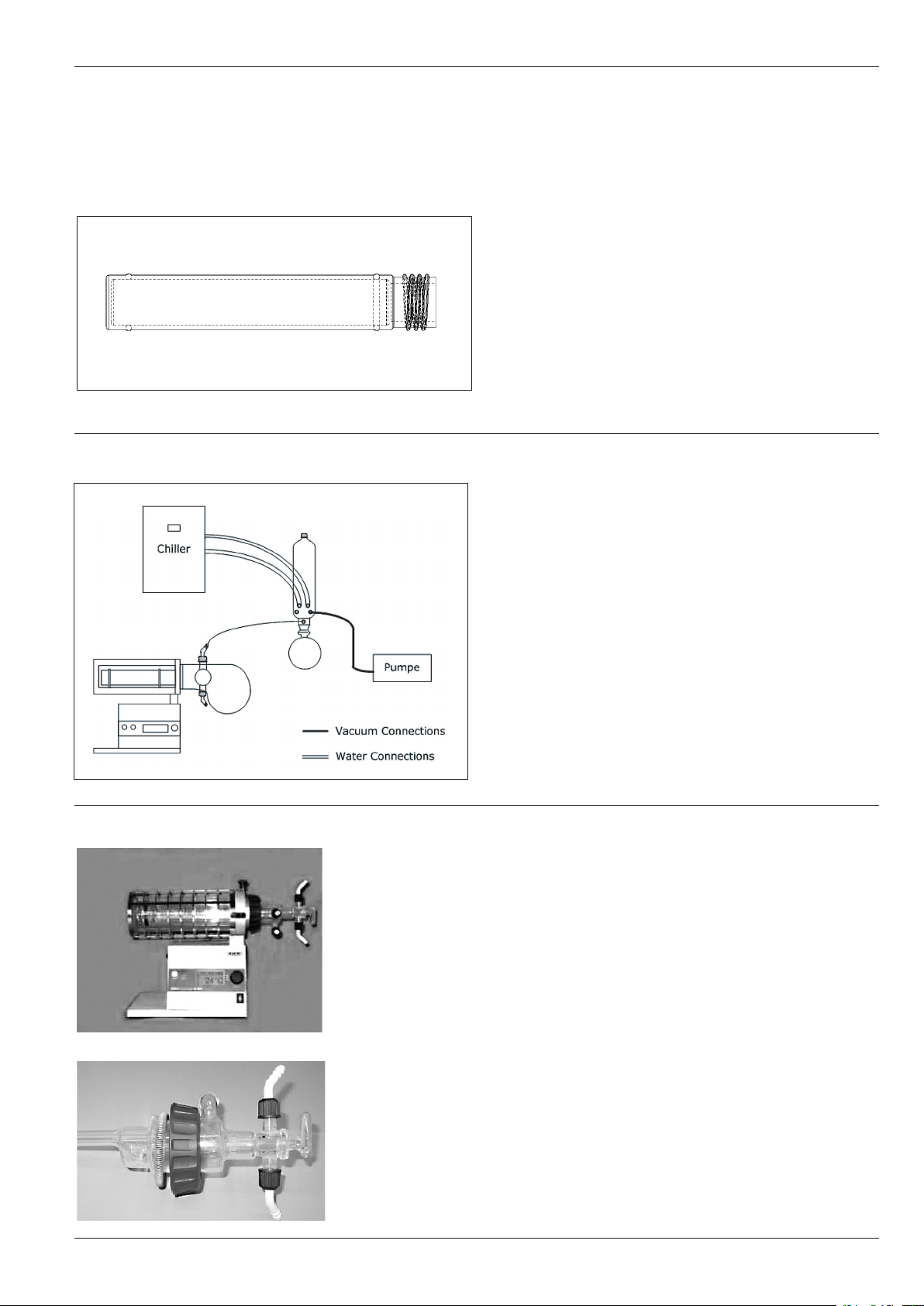
5.5.4 Operation method of freeze drying
The first step of each freee drying process is the complete
freezing of the product which preferably happens in the
freeze drying tube.
Fig. 24: Scheme of freeze drying
Before the freezing drying process starts, the system (pump,
Chiller) must have reached steady state. The chiller must be
cooled down to operation temperature of -30°C to -40°C
and the vaccum pump should be warm, before evacuation.
If the samples is in frozen condition in the freeze drying tube,
the B-585 is evacuated. The vacuum which can be chosen
depends upon the freezing point of the product. Set a vacuum pressure, which ensures a product temperature 10
degrees below the melting point during the drying process.
5.6 Converting the Glass Oven
5.6.1 From the drying configuration to sublimati-
on configuration
With the help of the sublimation accessory samples that sublime onto the cooling finger may be separeted from a mixture.
For additional cooling of the cooling finger, water can be used.
When using cooling water, the upper hose connection should
always be used as the water’s outlet.
Fig. 25: Glass oven with sublimation accessory
Sublimation processes usually require the use of vacuum. Ensure
that the O-ring seal is inserted properly into its groove before
the two glass parts are flanged together.
Once the sublimation has finished, switch off and leave the
instrument to cool down. Pull out the drying accessory and
install the flange on the sublimation accessory.
23
Page 26

Glass Oven B-585
5 Operation
5.6.2 From drying to freeze drying
The freeze drying accessory is immersed into the drying
accessory and the vacuum is put on.
5.6.3 From drying configurationto Kugelrohr
configuration
First of all switch off the instrument and let it cool down (if
it is necessary)
Fig. 26a:
Fig. 26b: Screw on sleeves
Removing drying accessory
The complete drying part has to be removed
· screw in the two sleeves, to faciliate the moving of the
drive unit.
· The iris diaphragm can be screwed on
Fig. 26c: Iris diaphragm with fixing screw
24
Page 27

Glass Oven B-585
2
7
1
Fig. 26d: Drive unit with sleeves positioned
5
4
5 Operation
· To install the drive unit, remove the connection (2) at the
end of the rods (1), insert the rods into the openings (3)
on the glass oven. Fix up the connection (2) again on
the rods.
3
· The cooling plate assembly (4) is fastened to the openings (5) in the support frame
Fig. 26e: Cooling device
Fig. 26f: Socket for plug in the drive unit
The connection cable (7) for the drive unit has to be plugged
into the lower plug socket (6) on the left side of the instrument (drive).
6
5.6.4 From Kugelrohr configuration to drying
configuration
Converting from ball tube distillation to drying is done by following the instructions in Chapter 5.3.2 in the opposite order.
To find out how to operate the drying oven, see Chapter 5.3.
25
Page 28

Glass Oven B-5856 Maintenance
6 Maintenance
All guidelines which are meant to keep the glass oven in working
order should be followed. This also includes a periodic cleaning
and checking for any visible damage.
6.1 Cleaning
The housing of the B-580 glass oven is coated with paint. Clean
only with dry rag or a rag moistened with alcohol.
While cleaning the oven, you should make sure that the iris dia phra gm does not become dirty.
The inner oven space is best clea ned with a moist rag. Any kind
of solvent may be used to do so.
Never rinse the oven out with running water or wash it using a
lot of water. Water could get between the outer and inner glass
layers where the heater is and cause an electrical short circuit.
If water should accidentally get in the iris diaphragm, you should
dry it out by placing the entire oven in a vacuum (vacuum drying
cabinet) at 40°C for several hours before you start using it again.
6.2 Service
The service of the device is limited to the ball tube drive, in which
the vacuum gasket and the rubber seal in the GL 14 may leak
after prolonged usage.
6.3 Customer service
The device may only be serviced by authorized service personnel. Such persons will have undergone fundamental technical
trai ning and have knowledge of the hazards associated with
not fol lowing the safety precautions. Büchi customer service
centres have device-specific service instructions which can only
be obtai ned by authorized personnel.
The addresses of the official Büchi customer service centres can
be found on the back cover of these instructions. Contact one
of these locations in case you encounter malfunctions or if you
have technical questions, or application-specific problems.
The Customer Service Department of the Büchi company is
available for the following services:
• Replacementparts(pleaseusethepartnumberslistedinthe
replacement parts list in the Appendix)
• Repairservices
• Maintenanceservices
• Technicalconsulting
26
Page 29

Glass Oven B-585 7 Taking out of operation
7 Taking out of operation
The device must be cooled down and thoroughly cleaned.
7.1 Storage/Transport
The device must be stored and transported in the original packaging, and must be thoroughly clean.
7.2 Disposal
To dispose of the glass oven in an environmentally friendly manner, you will find a list of the materials of all major parts in Chapter
9, Appendix. This guarantees that you can separate the parts
for recycling. To dispose of electrical parts, refer to the appropriate guidelines. You also must observe the regional and local
laws regarding disposal.
27
Page 30

Glass Oven B-5858 Replacement parts
complet Nr. 37010
02970
37287
36765
8 Replacement parts
Only original replacement parts that guaran tee the safe use and
functionality of the device. The use of replace ment parts and
supplies other than Büchi replace ment parts and supplies is only
allowed with the consent of the manufactu rer. For assembly and
dis assem bly purposes, replacement parts may only be used
accor ding to the descriptions in Chapter 6, Maintenance. The
manu facturing of this product, as described in these in struc tions, is prohibited.
8.1 B-585 Drying configuration replacement parts
Drying accessory complete 37010
Drying tube 02965
Flange ring 02970
10 Device fuses 3,15 AT 19659
End cap for drying 36765
Stopcock 37132
Set compr. Flange screw, spring and flange seal 37285
Set STJ clips (12 pieces) 37286
Set hose nipples GL 14 (4 pieces) 37287
02965
Fig. 27: Drying unit complete
37132
3728637285
28
Page 31

Glass Oven B-585 8 Replacement parts
8.2 B-585 Kugelrohr configuration replacement
37118
37101
37102
37286
37073
parts
Description Order Code
10 ml ball tube (Ns 14.5/23)
with vapour duct and clips 37118
37107
37104
37106
37286
37073
20ml ball tube (Ns 14.5/23)
with vapour duct and clips 37107
37117
37143
Fig. 28: Kugelrohr
Fig. 29: Hose connection assembly with stopcock
36478
37288
36480
36771
36479
37286
37286
37286
37132
37287
37073
37125
40ml ball tube (Ns 14.5/23)
with vapour duct and clips 37117
Rotation drying flask with vapour duct and
clip 37143
Communication cable B-585/V-5xx 46728
10 Device fuses 3,15 AT 19659
Connection piece 36771
Stopcock 37132
Cooling dish 37152
Set STJ (12 pieces) 37286
Set hose nipples GL14 (4 pieces) 37287
Set vacuum gaskets (5 pieces) 37288
Nozzle cap 36824
Chlambing cone 36770
complet 37133
36766
02965
Fig. 30: Sublimation accessory complet
37285
37287
37286
37132
8.3 Sublimation accessory replacement parts
Complete sublimation accessory 37133
Drying tube 02965
Flange ring 02970
Sublimation insert 36766
Cock 37132
Set flange screw, spring, gasket 37285
Set STJ (12 pieces) 37286
Set hose nipples GL14 (4 pieces) 37287
29
Page 32

Glass Oven B-585
9 Appendix
9 Appendix
9.1 Technical data
Supply voltage 100 - 230 VAC +/-10 %
Frequency 50/60 Hz
Power max. 450 W
Pin assignment Pin 1: Ground (Gnd)
Pin 2: + 24 V DC
Pin 3 to 8: not assigned
Warm-up time ca. 10 min. (from 20°C to 300°C)
Temperature regulation range 40-300°C
Temperature accuracy +/- 5°C (in the middle of the oven at 300°C)
Drying Drying volume max. 100-250 ml
Dimensions 410 x 300 x 300 (width x depth x heigth)
Weight 9.5 kg
Kugelrohr Distillation volume max. 10-60ml
Rotational speed 0-50 rpm.
Dimensions 650 x 300 x 300 (width x depth x heigth)
Weight 11.5 kg
Ambient temperature 5-40°C
Installation category II
Pollution degree 2
Environmental conditions for indoor use only, altitude up to 2000 m.
maximum relativ humidity 80% for temperatures up to 30°C
decreasin linearly to 50% relative humidity at 40°C
9.2 Error messages
Error message Possible cause Remedy
Main switch dors not Device is turned off, power supply Switch on the device, check power supply
light up voltages is missing or fuse defective voltage and fuses
No temperature Display or print defective Check power supply voltage/fuses and replace them,
indication send device to service center
Oven does not heat Nopower supply voltage or fuses Check heating leed,
defective
Motor does not turn Device is turned off, no mains voltage Switch on the instrument,
or fuses devective, motor set is on checkt the controll cable,
0 r/min, controll cable is not pluged please contact the service department
in properly,
E1 Internal temperature sensor defective Please contact service department
E2 Internal temperature sensor defective Please contact service department
E3 Internal temperature sensor defective Please contact service department
E9 Heating cefective Please contact service department
E10-11 Heating cefective Please contact service department
30
Page 33

Glass Oven B-585
9.3 Materials used
Description Materials Material code
Housing Steel sheet metal ST 12
Heating tube Borosilicate glass
Glass jacket tube Borosilicate glass
Cooling dish Hard-polyethylene HD-PE
Heater fixture (site) Aluminium ALMGSI 1
Kugelrohr-Insert Aluminium ALMGSI 1
Kugelrohr-housing Polyacetal POM
Heating flange Aluminium ALMGSI 1
9 Appendix
31
Page 34

Glass Oven B-585
9 Appendix
32
 Loading...