


 Loading...
TC-32BQT/32BFT/22B/S2C/31B/32BN/S2Cz/S2D/R2B |
Title |
|
|
TC-32B - NC
TC-22B - NC
TC-S2C - NC
TC-31B - NC
TC-32BN- NC
TC-S2Cz- NC
TC-S2D - NC
TC-R2B - NC
PROGRAMMING
MANUAL
Please read this manual carefully before starting operation.
2009/08/27 |
1 |
eTCOM2NCPRT.doc1 |

Title |
TC-32BQT/32BFT/22B/S2C/31B/32BN/S2Cz/S2D/R2B |
|
|
This manual describes the NC-Programming of the TC-32B, 22B, S2C, 31B, 32BN, S2Cz, S2D and R2B.
The tapping centre is able to perform drilling, tapping, and facing.
We shall not bear any responsibility for accidents caused by user's special handling or handling deviating from the generally recognized safe operation.
The relation between the manuals is as follows.
-OPERATION MANUAL
This manual describes the operations of the machine.
-INSTALLATION MANUAL
This manual describes the installation of the machine.
-PROGRAMMING MANUAL
This manual describes the programming of the machine.
Keep this manual for future reference.
Please include this manual when reselling this product.
When this manual or labels are lost or damaged, please replace them (charged) from your nearest agency.
2009/08/27 |
2 |
eTCOM2NCPRT.doc |

TC-32BQT/32BFT/22B/S2C/31B/32BN/S2Cz/S2D/R2B |
Title |
|
|
INTRODUCTION
Congratulations on your purchase of the Brother CNC tapping center. Correct usage of the machine is of most importance to assure the expected machine capabilities and functions as well as operator's safety. Read this Manual thoroughly before starting operation.
*All rights reserved: No part of this manual may be reproduced, stored in a retrieval system, or transmitted in any form without prior permission of the manufacturer.
*The contents of this Manual are subject to change without notice.
*This manual are complied with utmost care. If you encounter any question or doubt, please contact your local dealer.
2009/08/27 |
3 |
eTCOM2NCPRT.doc1 |

Title |
TC-32BQT/32BFT/22B/S2C/31B/32BN/S2Cz/S2D/R2B |
|
|
HOW TO USE THE MANUAL
This Instruction Manual consists of the following elements:
(1)General description Is an outline of the description given in the section.
(2) Alarm |
Is a alert given against a danger which may cause serious |
|
damage or death to human being or may damage the machine. |
The hazards are explained in this order: degree of danger,
subject of danger, expected damage, preventive measure,
(3)Operation procedure Is a procedure of activating a function.
(4) Screen |
Is given to describe important points of a procedure given. |
NOTE: This screen is only a representation of the information displayed on the actual screen and therefore differs somewhat from the actual screen layout and screen fonts.
(5)Illustration Is a sketch, figure, view, etc. indicating dimensions, position or zone, given in the points where it is necessary to provide complementary information to the text description.
(2) Alarm |
(3) Operation procedure |
(1) General description |
|
|
1.3 Precautions of first
WARNING
Dropping a heavy object onto your foot may fracture your foot bones.
When lifting heavy objects, wear safety shoes.
1.3.1Before starting operation
Before starting operation careful to read bellow.
(1)Turn off the main power breaker handle on
the control box door. Never touch the primary side power source or the terminal of the main power breaker, as these have high voltage applied.
(2)Put up a signboard which says' Under Maintenance (3)Never allow people to approach the machine,
particularly moving areas.
(4)Do not place any unnecessary object around the machine.
(5)Wear a helmet and safety shoes.
1 - 2 1 - 3
(5) Illustration (4) Screen
2009/08/27 |
4 |
eTCOM2NCPRT.doc |

TC-32BQT/32BFT/22B/S2C/31B/32BN/S2Cz/S2D/R2B Contents
Chapter 1 |
Program Composition---------------------- |
1-1 |
|
1.1 |
Types and composition of program ----------------------------------- |
1-2 |
|
1.2 |
Composition of block ------------------------------------------------------ |
1-2 |
|
1.3 |
Composition of word ------------------------------------------------------- |
1-3 |
|
1.4 |
Numerical values --------------------------------------------------------- |
1-3 |
|
1.5 |
Sequence number-------------------------------------------------------------- |
1-4 |
|
1.6 |
Optional block skip ------------------------------------------------------------ |
1-4 |
|
1.7 |
Control out/in function-------------------------------------------------------- |
1-4 |
|
Chapter 2 |
Coordinate Command---------------------- |
2-1 |
|
2.1 |
Coordinate system and coordinate value ------------------------------ |
2-2 |
|
2.2 |
Machine zero point and machine coordinate system -------------- |
2-3 |
|
2.3 |
Working coordinate system------------------------------------------------- |
2-3 |
|
Chapter 3 |
Preparation Function----------------------- |
3-1 |
|
3.1 |
Outline of G code--------------------------------------------------------------- |
3-3 |
|
3.2 |
Positioning (G00) --------------------------------------------------------------- |
3-7 |
|
3.3 |
Linear interpolation (G01) --------------------------------------------------- |
3-8 |
|
|
3.3.1 Chamfering to desired angle and cornering C--------------------------------------------- |
3-9 |
|
3.4 |
Circular/helical interpolation (G02, G03)-------------------------------- |
3-12 |
|
|
3.4.1 Circular interpolation------------------------------------------------------------------------- |
3-12 |
|
|
3.4.1.1 |
Circular interpolation-------------------------------------------------------------------- |
3-12 |
|
3.4.1.2 |
XZ Circular interpolation --------------------------------------------------------------- |
3-13 |
|
3.4.1.3 |
YZ Circular interpolation --------------------------------------------------------------- |
3-14 |
|
3.4.2 Helical thread cutting interpolation--------------------------------------------------------- |
3-18 |
|
|
3.4.3 Spiral interpolation (G02, G03) ------------------------------------------------------------- |
3-19 |
|
|
3.4.4 Conical interpolation (G02, G03)----------------------------------------------------------- |
3-21 |
|
3.4.5Tool dia offset procedure for spiral interpolation and conical interpolation
|
|
(G02, G03)------------------------------------------------------------------------------------- |
3-24 |
3.5 |
Circle Cutting (G12, G13) ---------------------------------------------------- |
3-25 |
|
3.6 |
Plane Selection (G17, G18, G19)------------------------------------------- |
3-26 |
|
3.7 |
Dwell (G04) ----------------------------------------------------------------------- |
3-26 |
|
3.8 |
Exact stop check (G09, G61, G64) ---------------------------------------- |
3-27 |
|
3.9 |
Programmable data input (G10) ------------------------------------------- |
3-28 |
|
3.10 |
Soft limit--------------------------------------------------------------------------- |
3-30 |
|
3.10.1 |
Stroke ----------------------------------------------------------------------------------------- |
3-30 |
|
3.10.2 |
Stroke limit ----------------------------------------------------------------------------------- |
3-30 |
|
3.10.3 Programmable stroke limit (G22) --------------------------------------------------------- |
3-31 |
||
3.11 |
Return to the reference point (G28) -------------------------------------- |
3-31 |
|
3.12 |
Return from the reference point (G29) ---------------------------------- |
3-32 |
|
3.13 |
Return to the 2nd to 6th reference point (G30) ----------------------- |
3-32 |
|
3.14 |
Selection of machine coordinate system (G53) ---------------------- |
3-33 |
|
3.15 |
Selection of working coordinate system (G54~G59) --------------- |
3-33 |
|
3.16 |
Additional working coordinate system selection (G54.1)--------- |
3-33 |
|
3.17 |
Scaling (G50, G51) ------------------------------------------------------------- |
3-34 |
|
|
|
|
|
2009/08/27 |
|
1 |
eTCOM2NCPRC.doc |
Contents |
TC - 32BQT/32BFT/22B/S2C/31B/32BN/S2Cz/S2D/R2B |
|
|
|
|
3.18 |
Programmable Mirror Image (G50.1, G51.1) --------------------------- |
3-38 |
3.19 |
Rotational transformation function (G68, G69)----------------------- |
3-40 |
3.20 |
Coordinate rotation using measured results (G168) --------------- |
3-42 |
3.21 |
Absolute command and incremental command (G90, G91) ----- |
3-42 |
3.22 |
Change of workpiece coordinate system (G92) ---------------------- |
3-44 |
3.23 |
Skip function (G31, G131, G132) ------------------------------------------ |
3-46 |
3.24 |
Continuous skip function (G31) ------------------------------------------- |
3-46 |
3.25 |
Change of tap twisting direction (G133,G134)------------------------ |
3-47 |
3.26 |
High speed peck drilling cycle (G173))---------------------------------- |
3-47 |
3.27 |
Peck drilling cycle (G183) |
3-49 |
3.28 |
Local coordinate system function --------------------------------(G52) |
3-51 |
3.29 |
Single direction positioning ---------------------------function (G60) |
3-51 |
3.30 |
G code priority ------------------------------------------------------------------ |
3-52 |
Chapter 4 |
Preparation Function (tool offset function) |
---4-1 |
||
4.1 |
Tool Dia Offset (G40,G41,G42) --------------------------------------------- |
4-2 |
||
|
4.1.1 Tool dia offset function ---------------------------------------------------------------------- |
4-2 |
||
|
4.1.1.1 Wear offset of tool diameter------------------------------------------------------------ |
4-2 |
||
|
4.1.2 |
Cancel Mode --------------------------------------------------------------------------------- |
4-3 |
|
|
4.1.3 |
Start -up ---------------------------------------------------------------------------------------- |
4-4 |
|
|
4.1.3.1 |
Inside cutting ---------------------------------------------------------------------------- |
4-4 |
|
|
4.1.3.2 |
Outside cutting --------------------------------------------------------------------------- |
4-5 |
|
|
4.1.3.3 Outside cutting (θ < 90°)---------------------------------------------------------------- |
4-6 |
||
|
4.1.4 |
|
Offset Mode ---------------------------------------------------------------------------------- |
4-7 |
|
4.1.4.1 |
Inside cutting ----------------------------------------------------------------------------- |
4-7 |
|
|
4.1.4.2 Outside cutting (90° ≤ θ < 180°)------------------------------------------------------- |
4-9 |
||
|
4.1.4.3 Outside cutting (θ < 90°)---------------------------------------------------------------- |
4-10 |
||
|
4.1.4.4 |
Exceptional case ------------------------------------------------------------------------- |
4-11 |
|
|
4.1.5 |
Offset Cancel ---------------------------------------------------------------------------------- |
4-12 |
|
|
4.1.5.1 Inside cutting (180° ≤ θ) ---------------------------------------------------------------- |
4-12 |
||
|
4.1.5.2 Outside cutting (90° ≤ θ < 180°)------------------------------------------------------- |
4-13 |
||
|
4.1.5.3 Outside cutting (θ < 90°)---------------------------------------------------------------- |
4-14 |
||
|
4.1.6 |
G40 single command ------------------------------------------------------------------------- |
4-15 |
|
|
4.1.7 Change of offset direction in offset mode ------------------------------------------------- |
4-16 |
||
|
4.1.8 Change of offset direction in offset mode ------------------------------------------------ |
4-17 |
||
|
4.1.8.1 When there is a cross point ------------------------------------------------------------ |
4-17 |
||
|
4.1.8.2 When there is no cross point ---------------------------------------------------------- |
4-18 |
||
|
4.1.8.3 When offset path becomes more than a circle---------------------------------------- |
4-19 |
||
|
4.1.9 G code command for tool dia offset in offset mode -------------------------------------- |
4-20 |
||
|
4.1.10 Notes on tool dia offset----------------------------------------------------------------------- |
4-21 |
||
|
4.1.11 Override function related to tool dia offset ------------------------------------------------ |
4-27 |
||
|
4.1.11.1 Automatic corner override ------------------------------------------------------------ |
4-27 |
||
|
4.1.11.2 Override of the inside circular cutting ----------------------------------------------- |
4-28 |
||
|
4.2 |
|
Tool length offset (G43, G44, G49)--------------------------------- |
4-29 |
|
4.2.1 Wear offset of tool length-------------------------------------------------------------------- |
4-29 |
||
|
|
|
|
|
2009/08/27 |
|
2 |
eTCOM2NCPRC.doc |
|

TC-32BQT/32BFT/22B/S2C/31B/32BN/S2Cz/S2D/R2B Contents
Chapter 5 |
Preparation Function (canned cycle) ------------ |
5-1 |
|
5.1 |
List of canned cycle function --------------------------------------------- |
5-2 |
|
5.2 |
Basic motions in canned cycle -------------------------------------------- |
5-3 |
|
5.3 |
General description of canned cycle ----------------------------------- |
5-4 |
|
|
5.3.1 |
Command related to canned cycle motions ---------------------------------------------- |
5-4 |
|
5.3.2 |
Setting of data in absolute / incremental command ------------------------------------- |
5-4 |
|
5.3.3 |
Types of return point (G98, G99) --------------------------------------------------------- |
5-5 |
|
5.3.4 |
Canned cycle motion conditions----------------------------------------------------------- |
5-5 |
|
5.3.5 |
Machining data of canned cycle ----------------------------------------------------------- |
5-6 |
|
5.3.6 |
Repeat number of canned cycle------------------------------------------------------------ |
5-7 |
5.4 |
Details of Canned Cycle------------------------------------------------------ |
5-8 |
|
|
5.4.1 |
High-speed peck drilling cycle (G73)----------------------------------------------------- |
5-8 |
|
5.4.2 |
Reverse tapping cycle (G74) --------------------------------------------------------------- |
5-9 |
|
5.4.3 |
Fine boring cycle (G76) -------------------------------------------------------------------- |
5-10 |
|
5.4.4 |
Tapping cycle (G77) ------------------------------------------------------------------------ |
5-11 |
|
5.4.5 |
Reverse tapping cycle (Synchro mode) (G78) ------------------------------------------- |
5-12 |
|
5.4.6 |
Drilling cycle (G81 G82) ------------------------------------------------------------------- |
5-13 |
|
5.4.7 |
Peck drilling cycle (G83) ------------------------------------------------------------------- |
5-15 |
|
5.4.8 |
Tapping cycle (G84) ------------------------------------------------------------------------ |
5-16 |
|
5.4.9 |
Boring cycle (G85, G89) ------------------------------------------------------------------- |
5-17 |
|
5.4.10 |
Boring cycle (G86) -------------------------------------------------------------------------- |
5-18 |
|
5.4.11 |
Back boring cycle (G87)-------------------------------------------------------------------- |
5-19 |
|
5.4.12 |
End mill tap cycle (G177) ------------------------------------------------------------------ |
5-20 |
|
5.4.13 |
End mill tap cycle (G178) ------------------------------------------------------------------ |
5-21 |
|
5.4.14 |
Double drilling cycle (G181, G182) ------------------------------------------------------ |
5-22 |
|
5.4.15 |
Double boring cycle (G185, G189) ------------------------------------------------------- |
5-23 |
|
5.4.16 |
Double boring cycle (G186) --------------------------------------------------------------- |
5-24 |
|
5.4.17 |
Canned cycle of reducing step ------------------------------------------------------------- |
5-25 |
|
5.4.18 |
Canned cycle cancel (G80)----------------------------------------------------------------- |
5-29 |
|
5.4.19 |
Notes on canned cycle --------------------------------------------------------------------- |
5-30 |
5.5 |
Canned cycle for tool change (non-stop ATC)(G100) -------------- |
5-31 |
|
Chapter 6 |
Preparation Function (coordinate calculation)6-1 |
||
6.1 |
List of coordinate calculation function---------------------------------- |
6-2 |
|
6.2 |
Coordinate calculation parameter ---------------------------------------- |
6-2 |
|
6.3 |
Details of coordinate calculation function ----------------------------- |
6-3 |
|
|
6.3.1 |
Bolt hole circle------------------------------------------------------------------------------- |
6-3 |
|
6.3.2 |
Linear (Angle) ------------------------------------------------------------------------------- |
6-3 |
|
6.3.3 |
Linear (X, Y)--------------------------------------------------------------------------------- |
6-4 |
|
6.3.4 |
Grid ----------------------------------------------------------------------------------------- |
6-5 |
6.4 |
Usage of coordinate calculation function ------------------------------ |
6-5 |
|
2009/08/27 |
3 |
eTCOM2NCPRC.doc |

Contents TC-32BQT/32BFT/22B/S2C/31B/32BN/S2Cz/S2D/R2B
Chapter 7 |
Macro------------------------------------------------------- |
7-1 |
|
7.1 |
What is a Macro? --------------------------------------------------------------- |
7-2 |
|
7.2 |
Variable Function--------------------------------------------------------------- |
7-3 |
|
|
7.2.1 |
Outline of variable function ---------------------------------------------------------------- |
7-3 |
|
7.2.2 |
Expression of variable ---------------------------------------------------------------------- |
7-3 |
|
7.2.3 |
Undefined variable -------------------------------------------------------------------------- |
7-4 |
|
7.2.4 |
Types of variables --------------------------------------------------------------------------- |
7-5 |
|
7.2.5 |
Variable display and setting---------------------------------------------------------------- |
7-6 |
|
7.2.6 |
System variable ------------------------------------------------------------------------------ |
7-6 |
7.3 |
Calculation Function -------------------------------------------------------- |
7-12 |
|
|
7.3.1 |
Calculation type ----------------------------------------------------------------------------- |
7-12 |
|
7.3.2 |
Calculation order ---------------------------------------------------------------------------- |
7-12 |
|
7.3.3 |
Precautions for calculation ----------------------------------------------------------------- |
7-13 |
7.4 |
Control Function-------------------------------------------------------------- |
7-14 |
|
|
7.4.1 |
GOTO statement (unconditional branch) ------------------------------------------------ |
7-14 |
|
7.4.2 |
IF statement (conditional branch)--------------------------------------------------------- |
7-14 |
|
7.4.3 |
WHILE statement (repetition)------------------------------------------------------------- |
7-15 |
|
7.4.4 |
Precautions for control function----------------------------------------------------------- |
7-16 |
7.5 |
Call |
Function------------------------------------------------------------------- |
7-18 |
|
7.5.1 |
Simple call function ------------------------------------------------------------------------ |
7-18 |
|
7.5.2 |
Modal call function ------------------------------------------------------------------------- |
7-19 |
|
7.5.3 |
Macro call argument------------------------------------------------------------------------ |
7-20 |
|
7.5.4 |
Difference between G65 and M98 -------------------------------------------------------- |
7-22 |
|
7.5.5 |
Multiple nesting call ------------------------------------------------------------------------ |
7-22 |
7.6 |
External Output Function ---------------------------------------------------- |
7-23 |
|
|
7.6.1 |
POPEN --------------------------------------------------------------------------------------- |
7-23 |
|
7.6.2 |
BPRNT --------------------------------------------------------------------------------------- |
7-23 |
|
7.6.3 |
DPRNT--------------------------------------------------------------------------------------- |
7-24 |
|
7.6.4 |
PCLOS --------------------------------------------------------------------------------------- |
7-25 |
|
7.6.5 |
Precautions on external output command------------------------------------------------ |
7-26 |
Chapter 8 |
Automatic work measurement--------------------- |
8-1 |
|
8.1 |
Before automatic work measurement ----------------------------------- |
8-4 |
|
8.2 |
Setting of data on automatic work measurement-------------------- |
8-4 |
|
8.3 |
Operation of automatic work measurement --------------------------- |
8-8 |
|
|
8.3.1 |
Corner----------------------------------------------------------------------------------------- |
8-8 |
|
8.3.2 |
Parallel ---------------------------------------------------------------------------------------- |
8-12 |
|
8.3.3 |
Circle------------------------------------------------------------------------------------------ |
8-14 |
|
8.3.4 |
Z level----------------------------------------------------------------------------------------- |
8-18 |
|
8.3.5 |
Positioning to the measurement position ------------------------------------------------- |
8-18 |
8.4 |
Handling of measured results---------------------------------------------- |
8-19 |
|
|
8.4.1 |
Display of the measured results------------------------------------------------------------ |
8-19 |
|
8.4.2 |
Reflection of measured results on the workpiece coordinate system ----------------- |
8-20 |
8.5 |
Lock key operations----------------------------------------------------------- |
8-21 |
|
|
|
|
|
2009/08/27 |
4 |
eTCOM2NCPRC.doc |
|

TC-32BQT/32BFT/22B/S2C/31B/32BN/S2Cz/S2D/R2B Contents
Chapter 9 |
High Accuracy Mode A -------------------------------- |
9-1 |
|
9.1 |
Outline ----------------------------------------------------------------------------- |
9-2 |
|
9.2 |
Usage------------------------------------------------------------------------------- |
9-3 |
|
|
9.2.1 |
User parameter setting --------------------------------------------------------------------- |
9-3 |
|
9.2.2 |
User parameter description----------------------------------------------------------------- |
9-4 |
|
9.2.3 |
Usage in a program-------------------------------------------------------------------------- |
9-5 |
|
9.2.4 |
Conditions available------------------------------------------------------------------------- |
9-6 |
|
9.2.5 |
Conditions where high accuracy mode A is released ----------------------------------- |
9-6 |
9.3 |
Restrictions ---------------------------------------------------------------------- |
9-7 |
|
|
9.3.1 |
Functions available ------------------------------------------------------------------------ |
9-7 |
|
9.3.2 |
Additional axis travel command----------------------------------------------------------- |
9-7 |
9.4 |
Effective Functions ------------------------------------------------------------ |
9-8 |
|
|
9.4.1 |
Automatic corner deceleration function -------------------------------------------------- |
9-8 |
|
9.4.2 |
Automatic arc deceleration function ----------------------------------------------------- |
9-9 |
|
9.4.3 |
Automatic curve approximation deceleration ------------------------------------------ |
9-10 |
Chapter 10 Subprogram function --------------------------------- |
10-1 |
|
10.1 |
Making subprogram ----------------------------------------------------------- |
10-2 |
10.2 |
Simple call --------------------------------------------------------------------- |
10-3 |
10.3 |
Return No. designation from sub program ---------------------------- |
10-4 |
10.4 |
Call with Sequence Number ------------------------------------------------ |
10-5 |
Chapter 11 |
Feed function-------------------------------------------- |
11-1 |
||
Chapter 12 |
S,T,M function------------------------------------------- |
12-1 |
||
12.1 |
S function ------------------------------------------------------------------------- |
12-2 |
||
12.2 |
T function ------------------------------------------------------------------------- |
12-2 |
||
|
12.2.1 Commanded by tool No.-------------------------------------------------------------------- |
12-2 |
||
|
12.2.2 Commanding by pot No. (magazine No.) ------------------------------------------------ |
12-2 |
||
|
12.2.3 Commanded by group No. ----------------------------------------------------------------- |
12-2 |
||
12.3 |
M function ------------------------------------------------------------------------ |
12-3 |
||
|
12.3.1 |
Program stop (M00)------------------------------------------------------------------------- |
12-7 |
|
|
12.3.2 |
Optional stop (M01)------------------------------------------------------------------------- |
12-7 |
|
|
12.3.3 |
End of program (M02, M30)--------------------------------------------------------------- |
12-7 |
|
|
12.3.4 Commands on the spindle (M03, M04, M05, M19, M111)---------------------------- |
12-7 |
||
|
12.3.4.1 |
Spindle orientation to desired angle (M19) -------------------------------------- |
12-7 |
|
|
12.3.5 |
M signal level output (M400~M409) ----------------------------------------------------- |
12-7 |
|
|
12.3.6 |
Tool change (M06) -------------------------------------------------------------------------- |
12-8 |
|
|
12.3.7 |
Workpiece counter specification (M211~M214)---------------------------------------- |
12-8 |
|
|
12.3.8 |
Workpiece counter cancel (M221~M224) ----------------------------------------------- |
12-8 |
|
|
12.3.8.1 |
Tool life counter --------------------------------------------------------------------- |
12-8 |
|
|
12.3.9 |
Tool breakage detection (M120 and M121)---------------------------------------------- |
12-8 |
|
|
12.3.10 |
Tool breakage detection (M200 and M201)---------------------------------------------- |
12-8 |
|
|
12.3.11 |
Tap time constant selection (M241 to 250) ---------------------------------------------- |
12-9 |
|
|
|
|
|
|
2009/08/27 |
|
5 |
eTCOM2NCPRC.doc |
|
Contents |
TC-32BQT/32BFT/22B/S2C/31B/32BN/S2Cz/S2D/R2B |
|
|
|
|
12.3.12 |
Pallet related M codes (M410, M411, M430, and M431)------------------------------ |
12-9 |
12.3.13 |
Unclamping and clamping C axis (M430 and M431) ---------------------------------- |
12-10 |
12.3.14 |
Unclamping and clamping B axis (M440 and M441) ---------------------------------- |
12-10 |
12.3.15 |
Unclamping and clamping A axis (M442 and M443) ---------------------------------- |
12-10 |
12.3.16 |
One-shot output (M450, M451, M455, and M456) ------------------------------------- |
12-10 |
12.3.17 |
Waiting until response is given (M460 to M469) --------------------------------------- |
12-11 |
12.3.18 |
Magazine rotate speed (M435 to M437)-------------------------------------------------- |
12-11 |
12.3.19 |
Magazine rotate to tool setting position (M501 to M599)------------------------------ |
12-11 |
12.3.20 |
Positioning finished check distance (M270 to M279) ---------------------------------- |
12-11 |
12.3.21 |
M codes related to shutter/cover (M434, M438, M439, M448, M449) -------------- |
12-12 |
12.3.22 |
Arm rotation speed change (low speed) (M432) ---------------------------------------- |
12-12 |
12.3.23 |
Tool replacement Z axis lower speed change (M290~M293) ------------------------- |
12-12 |
12.3.24 |
Tool replacement tool washing off (M497) ---------------------------------------------- |
12-12 |
12.3.25 |
Tool wash filter check (M294) ---------------------------------------------------------- |
12-13 |
12.3.26 |
Tool wash level sensor failure diagnosis (M295) --------------------------------------- |
12-13 |
Chapter 13 Option------------------------------------------------------ |
13-1 |
13.1 Programming precautions when using rotation axis--------------- |
13-2 |
2009/08/27 |
6 |
eTCOM2NCPRC.doc |
TC-32BQT/31BFT/22B/S2C/31B/32BN/S2Cz/S2D/R2B |
Quick index |
Chpt. 1 |
PROGRAM COMPOSITION |
|
|
|
|
Chpt. 2 |
COORDINATE COMMAND |
|
|
|
|
Chpt. 3 |
PREPARATION FUNCTION |
|
|
|
|
Chpt. 4 |
PREPARATION FUNCTION |
|
(TOOL OFFSET FUNCTION) |
||
|
||
Chpt. 5 |
PREPARATION FUNCTION (CANNED CYCLE) |
|
|
|
|
Chpt. 6 |
PREPARATION FUNCTION |
|
(COORDINATE CALCULATION)) |
||
|
||
Chpt. 7 |
MACRO |
|
|
|
|
Chpt. 8 |
AUTOMATIC WORK MEASUREMENT |
|
|
|
|
Chpt. 9 |
HIGH ACCURACY MODE A |
|
|
|
|
Chpt.10 |
SUBPROGRAM FUNCTION |
|
|
|
|
Chpt.11 |
FEED FUNCTION |
|
|
|
|
Chpt.12 |
S, T, M FUNCTION |
|
|
|
|
Chpt.13 |
OPTION |
|
|
|
1
2
3
4
5
6
7
8
8
9
10
11
12
13
2009/08/27 |
1 |
eTCOM2PRIN.doc |

Quick index |
TC-32BQT/31BFT/22B/S2C/31B/32BN/S2Cz/S2D/R2B |
(This page is blank.)
2009/08/27 |
2 |
eTCOM2PRIIN |

TC-32BQT/32BFT/22B/S2C/31B/32BN/S2Cz/S2D/R2B |
Chapter 1 Program Composition |
|
|
1
CHAPTER 1
PROGRAM COMPOSITION
1.1Types and composition of program
1.2Composition of block
1.3Composition of word
1.4Numerical values
1.5Sequence number
1.6Optional block skip
1.7Control out/in function
2009/08/27 |
1 - 1 |
eTCOM2NCPR1.doc |

Chapter 1 Program Composition |
TC-32BQT/32BFT/22B/S2C/31B/32BN/S2Cz/S2D/R2B |
|
|
1.1Types and Composition of Program
|
|
The program is divided into the main program and the subprogram. |
|
|
|
(1) Main program |
|
1 |
|
The main program is for machining one workpiece. While the main program is in use, a |
|
|
subprogram can be called to use the program more efficiently. |
||
|
|
Command M02 (or M30) to finish the main program. |
|
|
|
Main program |
|
|
|
N0001 G92X100; |
|
|
|
|
|
|
|
N0002 G00Z30 |
|
|
|
|
|
|
|
: |
|
|
|
: |
|
|
|
: |
|
|
|
M02; |
|
|
|
|
|
|
|
(2) Subprogram |
|
|
|
A subprogram is used by calling it from the main program or other subprograms. |
|
|
|
Command M99 to finish the subprogram. |
|
|
|
Subprogram |
|
|
|
N0100 G91X10; |
|
|
|
|
|
|
|
: |
|
|
|
: |
|
|
|
: |
|
|
|
M99; |
|
|
|
|
|
1.2 |
Composition of Block |
||
The program is composed of several commands. One command is called a block. A block is composed of one or more words. One block is discriminated from another block by an end of block code (EOB).
This manual expresses the end of block code by the symbol ";".
|
|
|
|
|
|
|
|
|
|
|
|
|
|
; |
N0001 G92X100 |
; |
|
; |
M02 |
; |
|
||||
|
|
|
|
|
|
|
|
|
|
|
|
|
|
|
|
|
|
|
|
|
|
|
|
|
|
|
|
|
Block |
|
|
|
|
|||||
|
|
|
|
|
|
|
|
Block |
|
|
||
|
|
|
|
|
|
|
|
|
|
|
|
|
|
|
|
|
|
|
|
|
|
|
|
|
|
|
|
|
|
|
|
|
|
|
|
|
|
|
(Note 1) The end of block code
ISO code : [LF] 0A(hexadecimal) EIA code : [CR] 80(hexadecimal)
(Note 2) One block has maximum 128 characters.
2009/08/27 |
1 - 2 |
eTCOM2NCPR1.doc |

TC-32BQT/32BFT/22B/S2C/31B/32BN/S2Cz/S2D/R2B |
Chapter 1 Program Composition |
|
|
1.3Compositiom of Word
A word is composed of an address and some digit of figures as shown below. (Algebraic sign + or - may added before a numerical value.)
|
X |
-1000 |
|
1 |
|
|
|
|
|||
|
|
|
|
|
|
Address |
numerical value |
|
|||
Word
(Note 1) The address uses one of the alphabetical letters.
(Note 2) The address "O" can not be used except for comments.
1.4Numerical Values
(1) Decimal point programming
Numerical values can be input in the following two ways and set by the user parameter1 (Switch 1).
Command type 1 (Standard)
Programmed command |
Commanded axis |
Actual amount (mm) |
Actual amount (inch) |
|
|
|
|
|
|
|
1 |
Feed axis |
1mm |
1 inch |
|
|
|
|
|
|
Rotation axis |
1 deg |
1 deg |
|
|
|
|||
|
|
|
|
|
|
1. |
Rotation axis |
1 mm |
1 inch |
|
|
|
|
|
|
|
Rotation axis |
1 deg |
1 deg |
|
|
|
|
|
Command type 2 (Minimum) |
|
|
||
Programmed command |
Commanded axis |
Actual amount (mm) |
Actual amount (inch) |
|
|
|
|
|
|
|
1 |
Feed axis |
0.001 mm |
0.0001 inch |
|
|
|
|
|
|
Rotation axis |
0.001 deg |
0.001 deg |
|
|
|
|||
|
|
|
|
|
|
1. |
Rotation axis |
1 mm |
1 inch |
|
|
|
|
|
|
|
Rotation axis |
1 deg |
1 deg |
|
|
|
|
|
(Note) |
User parameter : Refer to Instruction manual. |
|
||
(2) Programmable range of address
The programmable range deffers depending on the address. The digits less than the minimum range are ignored.
2009/08/27 |
1 - 3 |
eTCOM2NCPR1.doc |
Chapter 1 Program Composition |
TC-32BQT/32BFT/22B/S2C/31B/32BN/S2Cz/S2D/R2B |
|
|
1.5Sequence Number
A sequence number (1~99999) can be used following the address N for each block.
|
Command format |
N *****; |
|
||
|
|
|
|
|
|
1 |
i) |
A sequence number is used following the address N. |
|||
ii) |
A sequence number can be specified with up to 5-digit number. |
||||
|
|||||
(Note 1) The sequence number "N0" should not be used. (Note 2) It is used at the head of a block.
Ex.) N0100 G90X100;
When a block has a slash (/) code at the head of block (the optional block skip is commanded), a sequence number can be used either before or after it.
Ex.) N0100/ G90X100; or /N0100 G90X100;
(Note 3)
The order of sequence numbers is arbitary and need not be consecutive. (Note 4)
The sequence number is recognized as numerical values. Therefore such numerical values as 0001, 001, 01 and 1 are regarded as the same number.
1.6Optional Block Skip
When a block has a slash (/) code at the start and [BLOCK SKIP] key on the operation panel is turned ON, all information in the block with the slash code is ignored during the automatic operation.
If the [BLOCK SKIP] key is OFF, information in the block with the slash code is effective. That is, the block with a slash code can selectively be skipped.
..... ; |
/ N0100 G00X100 ..... |
; |
N0101 ..... |
Ignore these words
(Note 1)
A slash (/) code must be put at the start of a block. If it is placed elsewhere in the block, an alarm is generated.
This code can be also put right after a sequence number. (Note 2)
In the single block mode during automatic operation, when the [BLOCK SKIP] key is ON the operation does not stop at a block with a slash code, but stops at the next block.
1.7Control Out/In Function
For a easier look at the program, comments can be inserted in the program.
The comment is discriminated from operation by "(" and ")" at the start and the end.
( |
|
............. ) |
|
|
|
|
|
(Ex.) |
N1000 G00X200 (PRO-1); |
||
(Note)
A comment including the control out and in codes should not be longer than one block.
2009/08/27 |
1 - 4 |
eTCOM2NCPR1.doc |

TC-32BQT/32BFT/22B/S2C/31B/32BN/S2Cz/S2D/R2B |
Chapter 2 Coordinate Command |
|
|
2
CHAPTER 2
COORDINATE COMMAND
2.1Coordinate system and coordinate value
2.2Machine zero point and machine coordinate system
2.3Working coordinate system
2009/08/27 |
2 - 1 |
eTCOM2NCPR2.doc |
Chapter 2 Coordinate Command |
TC-32BQT/32BFT/22B/S2C/31B/32BN/S2Cz/S2D/R2B |
|
|
2.1Coordinate system and coordinate value
Coordinate values should be set in one coordinate system to specify a tool movement.
There are two types of coordinate systems.
(i)Machine coordinate system
(ii)Working coordinate system
The coordinate values are expressed by each component of the program axes (X, Y and Z for this unit).
2
Z
Y
Tool target position:
Commanded X20.Y10.Z15.;
15
10
X
0 |
20 |
|
eNCPR2.01.ai
2009/08/27 |
2 - 2 |
eTCOM2NCPR2.doc |
TC-32BQT/32BFT/22B/S2C/31B/32BN/S2Cz/S2D/R2B |
Chapter 2 Coordinate Command |
|
|
2.2Machine Zero Point and Machine Coordinate System
(1) Machine zero point
The machine zero point is the reference point on the machine.
(2) Machine coordinate system |
|
|
|
The coordinate systen with the machine zero point as its reference point is called the machine |
|
||
coordinate system. Each machine has its own coordinate system. |
2 |
||
|
|
|
|
|
|
Machine zero point |
|
|
X axis stroke |
(0,0,0) |
|
-X
Y axis stroke
Table
-Y
eNCPR2.02.ai
2.3Working Coordinate System
The working coordinate system is used to specify a tool motion for each workpiece.
A coordinate system previously set in the "Data Bank" is once selected, programming afterward can be easily done by specifying that coordinate system.
Each coordinate system is set by using an offset amount from the machine zero point to the working zero position.
(Note) Data Bank : Refer to Operation manual for the data.
2009/08/27 |
2 - 3 |
eTCOM2NCPR2.doc |

Chapter 2 Coordinate Command |
TC-32BQT/32BFT/22B/S2C/31B/32BN/S2Cz/S2D/R2B |
|
|
2
( This page is blank.)
2009/08/27 |
2 - 4 |
eTCOM2NCPR2.doc |
TC-32BQT/32BFT/22B/S2C/31B/32BN/S2Cz/S2D/R2B |
Chapter 3 Preparation Function |
|
|
CHAPTER 3 |
3 |
PREPARATION FUNCTION
3.1Outline of G code
3.2Positioning (G00)
3.3Linear interpolation (G01)
3.4Circular/helical thread cutting interpolation (G02, G03)
3.5Circle cutting (G12, G13)
3.6Plane selection (G17, G18, G19)
3.7Dwell (G04)
3.8Exact stop check (G09, G61, G64)
3.9Programmable data input (G10)
3.10Soft limit
3.11Return to the reference point (G28)
3.12Return from the reference point (G29)
3.13Return to the 2nd/3rd/4th reference point (G30)
3.14Selection of machine coordinate system (G53)
3.15Selection of working coordinate system (G54~G59)
3.16Additional working coordinate system selection (G54.1)
3.17Scaling (G50, G51)
3.18Programmable mirror image (G50.1, G51.1)
3.19Coordinate rotation function (G68, G69)
3.20Coordinate rotation using measured results (G168)
3.21Absolute command and incremental command (G90, G91)
3.22Change of working coordinate system (G92)
3.23Skip function (G31, G131, G132)
3.24Continuous skip function (G31)
2009/08/27 |
3 - 1 |
eTCOM2NCPR3.doc |

Chapter 3 Preparation Function |
TC-32BQT/32BFT/22B/S2C/31B/32BN/S2Cz/S2D/R2B |
|
|
|
|
3.25Change of tap twisting direction (G133, G134)
3.26High speed peck drilling cycle (G173)
3.27Peck drilling cycle (G183)
3.28Local coordinate system function (G52)
3.29Single direction positioning function (G60)
3.30G code priority
3
2009/08/27 |
3 - 2 |
eTCOM2NCPR3.doc |

TC-32BQT/32BFT/22B/S2C/31B/32BN/S2Cz/S2D/R2B |
Chapter 3 Preparation Function |
|
|
3.1Outline of G code
Within 3-digit number following the address G determines the meaning of the command of the block concerned.
The G codes are divided into the following two types.
Type |
Meaning |
Modal |
The G code is effective until another G code in the same group is commanded. |
|
|
One-shot |
The G code is effective only at the block in which it is specified. |
3
The G codes with * mark indicates the modal status when the power is turned ON.
(Note1) Details of coordinate calculation functions are described in " Chapter 6 ". (Note2) Details of tool dia offset are described in " Chapter 4 ".
Group |
G cord |
Contents |
Modal |
|
|
|
|
|
G00* |
Positioning |
|
|
|
|
|
|
G01 |
Linear interpolation |
|
|
|
|
|
|
G02 |
Circular/ helical interpolation (CW) |
|
|
|
|
|
|
G03 |
Circular / helical interpolation (CCW) |
Modal |
|
|
|
|
|
G102 |
XZ Circular interpolation (CW) |
|
|
|
||
|
|
|
|
|
G103 |
XZ Circular interpolation (CCW) |
|
|
|
|
|
|
G202 |
YZ Circular interpolation (CW) |
|
|
|
|
|
|
G203 |
YZ Circular interpolation (CCW) |
|
|
|
|
|
|
G04 |
Dwell |
One-shot |
|
|
|
|
|
G09 |
Exact stop check |
One-shot |
|
|
|
|
|
G10 |
Programmable data input |
One-shot |
|
|
|
|
|
G13 |
Circular cutting CCW |
One-shot |
|
|
|
|
|
G17* |
XY plane selection |
|
|
|
|
Modal |
|
G18 |
ZX plane selection |
|
|
|
|
|
|
G19 |
YZ plane selection |
|
|
|
|
|
|
G22* |
Programmable stroke limit on |
Modal |
|
|
|
|
|
G23 |
Programmable stroke limit cancel |
|
|
|
||
|
|
|
|
|
G28 |
Return to the reference point |
|
|
|
|
One-shot |
|
G29 |
Return from the reference point |
|
|
|
|
|
|
G30 |
Return to the 2nd /3rd/4th reference point |
|
|
G31 |
Skip function |
One-shot |
|
|
|
|
2009/08/27 |
3 - 3 |
eTCOM2NCPR3.doc |

|
Chapter 3 Preparation Function |
TC-32BQT/32BFT/22B/S2C/31B/32BN/S2Cz/S2D/R2B |
|||||
|
|
|
|
|
|
|
|
|
|
|
|
|
|
|
|
|
|
Group |
G cord |
Contents |
Modal |
|
|
|
|
|
|
|
|
|
|
|
|
|
G36 |
Coordinate calculation function (Bolt hole circle) |
|
|
|
|
|
|
|
|
|
|
|
|
|
|
G37 |
Coordinate calculation function (Line-angle) |
One-shot |
|
|
|
|
|
|
|
|
||
|
|
|
G38 |
Coordinate calculation function (Line-angle) |
|
|
|
|
|
|
|
|
|
||
|
|
|
|
|
|
|
|
|
|
|
G39 |
Coordinate calculation function (Grid) |
|
|
|
|
|
|
|
|
|
|
|
|
|
|
G40* |
Tool dia offset cancel |
|
|
|
|
|
|
|
|
Modal |
|
|
|
|
|
G41 |
Tool dia offset left |
|
|
|
3 |
|
|
|
|
|
|
|
|
|
G42 |
Tool dia offset right |
|
|
|
|
|
|
|
|
|
|
||
|
|
|
|
|
|
|
|
|
|
|
G43 |
Tool length offset + |
|
|
|
|
|
|
|
|
Modal |
|
|
|
|
|
G44 |
Tool length offset - |
|
|
|
|
|
|
|
|
|
|
|
|
|
|
G49* |
Tool length offset cancel |
|
|
|
|
|
|
|
|
|
|
|
|
|
|
G50* |
Scaling cancel |
Modal |
|
|
|
|
|
|
|
|
||
|
|
|
G51 |
Scaling |
|
|
|
|
|
|
|
|
|
||
|
|
|
|
|
|
|
|
|
|
|
G50.1 |
Mirror image cancel |
Modal |
|
|
|
|
|
|
|
|
||
|
|
|
G51.1 |
Mirror image |
|
|
|
|
|
|
|
|
|
||
|
|
|
|
|
|
|
|
|
|
|
G52 |
Local coordinate system |
One-shot |
|
|
|
|
|
|
|
|
||
|
|
|
G53 |
Machine coordinate system selection |
|
|
|
|
|
|
|
|
|
||
|
|
|
|
|
|
|
|
|
|
|
G54* |
Working coordinate system selection 1 |
|
|
|
|
|
|
|
|
|
|
|
|
|
|
G55 |
Working coordinate system selection 2 |
|
|
|
|
|
|
|
|
|
|
|
|
|
|
G56 |
Working coordinate system selection 3 |
|
|
|
|
|
|
|
|
Modal |
|
|
|
|
|
G57 |
Working coordinate system selection 4 |
|
|
|
|
|
|
|
|
|
|
|
|
|
|
G58 |
Working coordinate system selection 5 |
|
|
|
|
|
|
|
|
|
|
|
|
|
|
G59 |
Working coordinate system selection 6 |
|
|
|
|
|
|
|
|
|
|
|
|
|
|
G54.1 |
Extended working coordinate system selection |
|
|
|
|
|
|
|
|
|
|
|
|
|
|
G60 |
Single direction positioning |
One-shot |
|
|
|
|
|
|
|
|
|
|
|
|
|
G61 |
Exact stop mode |
Modal |
|
|
|
|
|
|
|
|
||
|
|
|
G64* |
Cutting mode |
|
|
|
|
|
|
|
|
|
||
|
|
|
|
|
|
|
|
|
|
|
G65 |
Macro call |
One-shot |
|
|
|
|
|
|
|
|
|
|
|
|
|
G66 |
Macro modal call |
Modal |
|
|
|
|
|
|
|
|
||
|
|
|
G67* |
Cancel macro modal call |
|
|
|
|
|
|
|
|
|
||
|
|
|
|
|
|
|
|
|
|
The G codes |
with * mark |
indicates the modal status when the power is turned |
ON. |
|
|
|
|
(Note1) Details of coordinate calculation functions are described in " Chapter 6 ". |
|
||||
|
|
(Note2) Details of tool dia offset are described in " Chapter 4 ". |
|
|
|
||
2009/08/27 |
3 - 4 |
eTCOM2NCPR3.doc |

TC-32BQT/32BFT/22B/S2C/31B/32BN/S2Cz/S2D/R2B |
Chapter 3 Preparation Function |
||||||
|
|
|
|
|
|
|
|
|
|
|
|
|
|
|
|
|
Group |
G cord |
Contents |
|
Modal |
|
|
|
|
|
|
|
|
|
|
|
|
G68 |
Coordinate rotation function |
|
|
|
|
|
|
|
|
Modal |
|
||
|
|
G69* |
Coordinate rotation function cancel |
|
|
||
|
|
|
|
|
|
|
|
|
|
G168 |
Coordinate rotation using measured results |
|
|
|
|
|
|
|
|
|
|
|
|
|
|
G90* |
Absolute command |
|
Modal |
|
|
|
|
|
|
|
|
||
|
|
G91 |
Incremental command |
|
|
|
|
|
|
|
|
|
|
||
|
|
|
|
|
|
||
|
|
G92 |
Working coordinate system setting |
One-shot |
3 |
||
|
|
|
|
|
|
||
|
|
G94 |
Feed rate per minute |
|
|
||
|
|
|
|
|
|
|
|
|
|
G98* |
Return to the initial point level |
|
Modal |
|
|
|
|
|
|
|
|
||
|
|
G99 |
Return to the R point level |
|
|
|
|
|
|
|
|
|
|
||
|
|
|
|
|
|
|
|
|
|
G73 |
Canned cycle (High-speed peck drilling cycle) |
|
|
|
|
|
|
|
|
|
|
|
|
|
|
G74 |
Canned cycle (Reverse tapping cycle) |
|
|
|
|
|
|
|
|
|
|
|
|
|
|
G76 |
Canned cycle (Fine boring cycle) |
|
|
|
|
|
|
|
|
|
|
|
|
|
|
G77 |
Canned cycle (Tapping cycle, synchro mode) |
|
|
|
|
|
|
|
|
|
|
|
|
|
|
G78 |
Canned cycle (Reverse tapping cycle, synchro |
|
|
|
|
|
|
mode) |
|
|
|
|
|
|
|
|
|
|
|
|
|
|
|
G80* |
Canned cycle cancel |
|
|
|
|
|
|
|
|
|
|
|
|
|
|
G81 |
Canned cycle (Drill, spot drilling cycle) |
|
|
|
|
|
|
|
|
|
|
|
|
|
|
G82 |
Canned cycle (Drill, spot drilling cycle) |
|
|
|
|
|
|
|
|
|
|
|
|
|
|
G83 |
Canned cycle (Peck drilling cycle) |
|
|
|
|
|
|
|
|
|
|
|
|
|
|
G84 |
Canned cycle (Tapping cycle) |
|
|
|
|
|
|
|
|
|
Modal |
|
|
|
|
G85 |
Canned cycle (Boring cycle) |
|
|
|
|
|
|
|
|
|
|
|
|
|
|
G86 |
Canned cycle (Boring cycle) |
|
|
|
|
|
|
|
|
|
|
|
|
|
|
G87 |
Canned cycle (Back boring cycle) |
|
|
|
|
|
|
|
|
|
|
|
|
|
|
G89 |
Canned cycle (Boring cycle) |
|
|
|
|
|
|
|
|
|
|
|
|
|
|
G177 |
Canned cycle (End mill tap cycle) |
|
|
|
|
|
|
|
|
|
|
|
|
|
|
G178 |
Canned cycle (End mill tap cycle) |
|
|
|
|
|
|
|
|
|
|
|
|
|
|
G181 |
Canned cycle (Double drilling cycle) |
|
|
|
|
|
|
|
|
|
|
|
|
|
|
G182 |
Canned cycle (Double drilling cycle) |
|
|
|
|
|
|
|
|
|
|
|
|
|
|
G185 |
Canned cycle (Double boring cycle) |
|
|
|
|
|
|
|
|
|
|
|
|
|
|
G186 |
Canned cycle (Double boring cycle) |
|
|
|
|
|
|
|
|
|
|
|
|
|
|
G189 |
Canned cycle (Double drilling cycle) |
|
|
|
|
|
|
|
|
|
|
|
|
The G codes with * mark indicates the modal status when the power is turned ON.
2009/08/27 |
3 - 5 |
eTCOM2NCPR3.doc |

Chapter 3 Preparation Function |
TC-32BQT/32BFT/22B/S2C/31B/32BN/S2Cz/S2D/R2B |
|||||
|
|
|
|
|
|
|
|
|
|
|
|
|
|
|
Group |
G cord |
Contents |
Modal |
|
|
|
|
|
|
|
|
|
|
|
G173 |
Canned cycle (High-speed peck drilling cycle) |
One-shot |
|
|
|
|
|
|
|
|
|
|
|
G183 |
Canned cycle cancel (Peck drilling cycle) |
One-shot |
|
|
|
|
|
|
|
|
|
|
|
G100 |
Non-stop automatic tool change |
One-shot |
|
|
|
|
|
|
|
|
|
The G codes with * mark indicates the modal status when the power is turned ON.
Note1) Details of canned cycle function are described in " Chapter 5 ".
|
Group |
G cord |
Contents |
Modal |
3 |
|
|
|
|
|
G120 |
Positioning to the measuring point |
One-shot |
|
|
|
G121 |
Automatic measurement Corner (Boss) |
|
|
|
|
|
|
|
|
G122 |
Automatic measurement Parallel (Groove) |
|
|
|
|
|
|
|
|
G123 |
Automatic measurement Parallel (Boss) |
|
|
|
|
|
|
|
|
G124 |
Automatic measurement Circle center (Hole, 3 points) |
|
|
|
|
|
One-shot |
|
|
G125 |
Automatic measurement Circle center (Boss, 3 points) |
|
|
|
|
|
|
|
|
G126 |
Automatic measurement Circle center (Hole, 4 points) |
|
|
|
|
|
|
|
|
G127 |
Automatic measurement Circle center (Boss, 4 points) |
|
|
|
|
|
|
|
|
G128 |
Automatic measurement Z-axis height |
|
|
|
|
|
|
|
|
G129 |
Automatic measurement Corner (Groove) |
|
|
|
|
|
|
|
|
G131 |
Measurement feed |
One-shot |
|
|
|
|
|
|
|
G132 |
Measurement feed |
|
|
|
|
||
|
|
|
|
|
|
|
G133 |
Changeover of tap twisting direction (CW) |
One-shot |
|
|
|
|
|
|
|
G134 |
Changeover of tap twisting direction (CCW) |
|
|
|
|
||
|
|
|
|
|
The G codes with * mark indicates the modal status when the power is turned ON.
(Note)
Commands G120 to G129 are described in detail in " Option, Automatic Measurement " in the instruction manual.
2009/08/27 |
3 - 6 |
eTCOM2NCPR3.doc |
TC-32BQT/32BFT/22B/S2C/31B/32BN/S2Cz/S2D/R2B |
Chapter 3 Preparation Function |
|
|
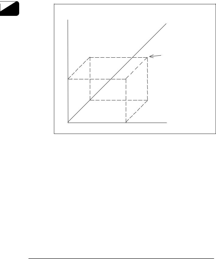
3.2Positioning (G00)
A tool moves from its current position to the end point at the rapid traverse rate in each axis direction independently. Therefore, a tool path is not always a linear line.
Command format |
G00 X_Y_Z_A_B_C_ ; |
|
|
When the additional axis is commanded and the optional additional axis is not installed, an alarm will occur.
In the positioning mode actuated by the G00 code, the execution proceeds to the next block after confirming the in-position check. (Note 1)
3
eNCPR3.01.ai
(Note 1)
In-position check is to confirm that the machine detecting position is within the specified range around the target (end) point.
(This range is set by the machine parameter for each axis.) (Note 2)
The rapid traverse rate is set by the machine parameter for each axis. Accordingly, rapid traverse rate cannot be specified by the F command.
2009/08/27 |
3 - 7 |
eTCOM2NCPR3.doc |

Chapter 3 Preparation Function |
TC-32BQT/32BFT/22B/S2C/31B/32BN/S2Cz/S2D/R2B |
|
|
|
|
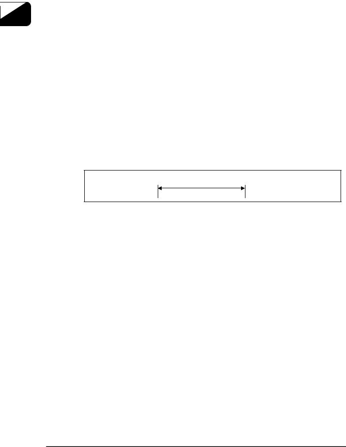
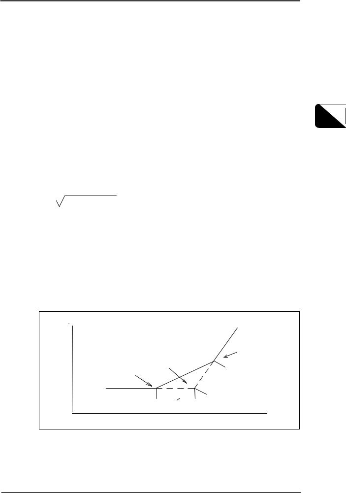
3.3Linear interpolation (G01)
Linear interpolation moves a tool linearly from the current position to the target position at the specified feed rate.
Command format |
G01 X_Y_(Z_A_B_) F_ ; |
|
|
Up to three linear axes and one additional axis can be controlled simultaneously.
|
When the additional axis is commanded and the optional additional axis is not installed, an alarm |
3 |
will occur. |
The feed rate is commanded by the address F. Once the feed rate is commanded, it is effective |
until another value is specified.
When the X, Y, and Z axes are commanded, the feed rate is determined by the value entered to mm / min.
When the additional axis is commanded, the feed rate is determined by the value entered to -/min.
End |
point |
Start |
point |
eNCPR3.2.ai
(Note 1) Feed rate along each axis is as follows: When " G01 G91 Xα Yβ Zγ Ff;" is programmed:
α
Feed rate along X axis |
Fx = |
─── · |
f |
|
|
L |
|
|
|
β |
|
Feed rate along Y axis: |
Fy = |
─── · |
f |
|
|
L |
|
|
|
γ |
|
Feed rate along Z axis: |
Fz = |
─── · |
f |
|
|
L |
|
( L = α2 + β2 + γ2 |
) |
|
|
2009/08/27 |
3 - 8 |
eTCOM2NCPR3.doc |
TC-32BQT/32BFT/22B/S2C/31B/32BN/S2Cz/S2D/R2B Chapter 3 Preparation Function
(Note2)
The example below shows linear interpolation of linear axis and rotation axis. When " G01 G91 Xα Yβ Zγ Bδ Ff;" is programmed:
Time taken for B-axis movement:1 |
Tb = |
L |
|
─── |
|||
|
|
δ |
f |
Feed rate along B axis: |
Fb = |
|
|
──── |
|
||
|
|
Tb |
|
|
|
α |
3 |
Feed rate along X axis |
Fx = |
─── · f |
|
|
|
L |
|
|
|
β |
|
Feed rate along Y axis: |
Fy = |
─── · f |
|
|
|
L |
|
|
|
γ |
|
Feed rate along Z axis: |
Fz = |
─── · f |
|
|
|
L |
|
( L = α2 + β2 + γ2 + δ2 |
) |
|
|
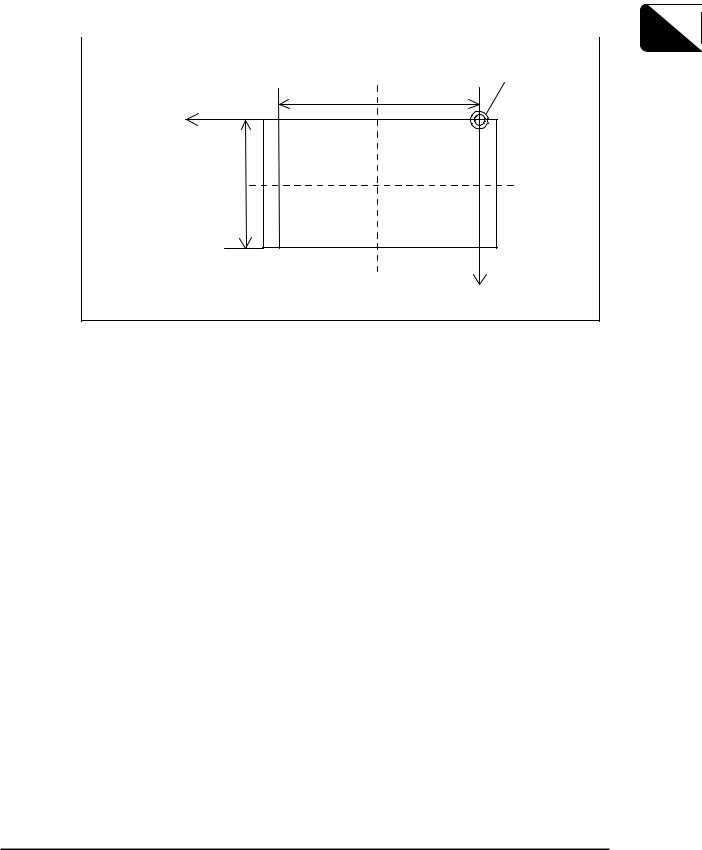
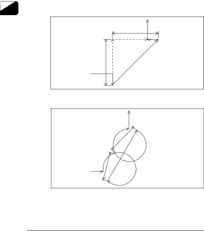
3.3.1Chamfering to desired angle and cornering C
Chamfering to the desired angle or rounding can be performed between interpolation commands.
Chamfering
Command format |
G01 X_Y_, C_ ; |
|
|
C: Distance from virtual corner to the chamfer start point and send point.
This can be commanded only for the selected plane surface.
Y
Virtual |
Chamfer end point |
corner |
|
intersection |
|
Chamfer start point |
|
|
c |
c |
|
|
X |
|
eNCPR3.03.ai |
2009/08/27 |
3 - 9 |
eTCOM2NCPR3.doc |
Chapter 3 Preparation Function |
TC-32BQT/32BFT/22B/S2C/31B/32BN/S2Cz/S2D/R2B |
|
|
|
|
(1)The corner chamfering command block and subsequent block must contain the interpolation command (G01-G03).
When the subsequent block does not contain an interpolation or movement command, an alarm will occur.
(2)The inserted block belongs to the corner chamfering command block. Thus, if the feed rate differs from the corner chamfering command block and the subsequent block , the inserted block moves at the feed rate of the corner
chamfering command block. Further, the program does not stop before the inserted block occurs even during single block operation. (It stops after the inserted block occurs.)
(3)Tool diameter offset applies to the configuration after corner chamfering is performed.
(4)When the chamfering amount is longer than the chamfering command block and feeding quantity of the subsequent block, set extended point from each blocks as "chamfer start point" and "chamfer end point".
3 |
Example.1: Liner cutting |
|
|
|
|
|
|
(4) |
|
|
C |
|
|
(7) |
|
|
(3) |
|
|
(2) |
|
C |
(6) |
|
|
|
|
(1) |
|
|
|
(5) |
eNCPR3.04.ai
When set the programmed path to (1.2.3.4.) and the block C as (2), operate to 1-5-6-7-4.
Example.2: Circular cutting
(4)
(3)
C
(7
(2)
(6)
C
(1)
(5)
eNCPR3.05.ai
When set the programmed path to (1.2.3.4.) and the block C as (2), operate to 1-5-6-7-4.
2009/08/27 |
3 - 10 |
eTCOM2NCPR3.doc |
Loading...