


Instruction Manual
Copyright July 01, 2016
Jim M. Bagley, GraceWood, Inc
(Reproduction Prohibited)
Version 1.0

Table of Contents
Table of Contents |
2 |
IMPORTANT SAFETY INSTRUCTIONS |
3 |
IMPORTANT SAFETY INSTRUCTIONS |
4 |
Specifications and Overview |
5 |
Specifications and Overview |
6 |
Parts List |
7 |
Step 1: Wheel Alignment |
8 |
Step 2: Installing the Encoder on the Carriage |
9 |
Step 3: Installing the Encoder on the Quilting Machine |
10 |
Step 4: Connecting and Setting Encoders |
11 |
Step 5: Attaching the Thread Mast |
12 |
Step 6: Connecting the Front Display |
12 |
Threading the Quilting Machine |
13 |
Winding Bobbins |
14 |
Installing the Bobbin Case |
15 |
Adjusting Thread Tension |
16 |
Plugging In The Cables |
17 |
Final Checklist |
18 |
Basic Controls |
19 |
Main Screen Options |
20 |
Sewing Modes |
21 |
Sewing Modes Continued |
22 |
Settings |
23 |
System Info |
24 |
Repair Kit |
25 |
The Needle Plate |
26 |
The Hook Holder |
27 |
Hopping Foot |
28 |
Timing The Machine |
29 |
Thread Tension |
30 |
Changing A Needle |
31 |
Cleaning Tension Discs |
31 |
Cleaning Bobbin Area |
32 |
Cleaning Bobbin Case |
32 |
Oiling the Machine: Head |
33 |
Oiling the Machine: Hook |
34 |
Troubleshooting |
35 |
Troubleshooting |
36 |
Needle Information |
37 |
Thread Information |
38 |
Additional Tips |
39 |
2
IMPORTANT SAFETY INSTRUCTIONS
When using an electrical machine, basic safety precautions should always be followed, including the following:
Read all instructions before using (this machine).
DANGER - To reduce the risk of electric shock:
1. The machine should never be left unattended when plugged in. Always unplug this machine from the electric outlet immediately after using and before cleaning.
WARNING - To reduce the risk of burns, fire, electric shock, or injury to persons:
1.Do not allow this machine to be used as a toy. Close attention is necessary when this machine is used by or near children.
2.Use this machine only for its intended use as described in this manual. Use only attachments recommended by the manufacturer as contained in this manual.
3.Never operate this machine if it has a damaged cord or plug, if it is not working properly, if it has been dropped or damaged, or dropped into water. Return the machine to the nearest authorized dealer or service center for examination, repair, electrical or mechanical adjustment.
4.Never operate the machine with any air openings blocked. Keep ventilation openings of the sewing machine free from the accumulation of lint, dust, and loose cloth.
5.Never drop or insert any object into any opening.
6.Do not use outdoors.
7.Do not operate where aerosol (spray) products are being used or where oxygen is being administered.
8.To disconnect, turn all controls to the off position, then remove the plug from the outlet.
9.Do not unplug by pulling on cord. To unplug, grasp the plug, not the cord.
ii)Keep fingers away from all moving parts. Special care is required around the sewing machine
needle.
iii)Always use the proper needle plate. The wrong plate can cause the needle to break.
iv)Do not use bent needles.
v)Do not pull or push fabric while stitching. It may deflect the needle causing it to break.
vi)Switch the sewing machine off when making any adjustments in the needle area, such as threading needle, changing needle, threading bobbin, or changing presser foot, etc.
vii)Always unplug sewing machine from the electrical outlet when removing covers, lubricating, or when making any other user servicing adjustments mentioned in the instruction manual.
Connect this machine to a properly grounded outlet only. See Grounding Instructions.
SAVE THESE INSTRUCTIONS
3
IMPORTANT SAFETY INSTRUCTIONS
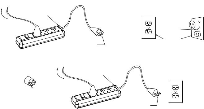
GROUNDING INSTRUCTIONS
This product must be grounded. In the event of malfunction or breakdown, grounding provides a path of least resistance for electric current to reduce the risk of electric shock. This product is equipped with a cord having an equipment-grounding conductor and a grounding plug. Plug the cord from the quilting machine into a surge protector. The surge protector must be plugged into an appropriate outlet that is properly installed and grounded in accordance with all local codes and ordinances.
DANGER - Improper connection of the equipment-grounding conductor can result in a risk of electric shock. The conductor with insulation having an outer surface that is green with or without yellow stripes is the equipment-grounding conductor. If repair or replacement of the cord or plug is necessary, do not connect the equipment-grounding conductor to a live terminal. Check with a qualified electrician or serviceman if the grounding instructions are not completely understood, or if in doubt as to whether the product is properly grounded.
Do not modify the plug provided with the product - if it will not fit the outlet, have a proper outlet installed by a qualified electrician.″
This product is for use on a nominal 120 V circuit, and has a grounding plug that looks like the plug illustrated in sketch A in Figure 61.1. A temporary adaptor, which looks like the adaptor illustrated in sketches B and C, may be used to connect this plug to a 2-pole receptacle as shown in sketch B if a properly grounded outlet is not available. The temporary adaptor should be used only until a properly grounded outlet can be installed by a qualified electrician. The green colored rigid ear, lug, and the like, extending from the adaptor must be connected to a permanent ground such as a properly grounded outlet box cover. Whenever the adaptor is used, it must be held in place by the metal screw.
A qualified electrician should be consulted if there is any doubt as to whether an outlet box is properly grounded.
Grounding Methods
Figure 61.1
Surge |
|
|
|
Protector |
|
|
|
|
|
Metal |
|
|
|
Screw |
|
|
Grounding |
Cover of |
|
|
Pin |
Grounded |
|
|
(A) |
Outlet Box |
(B) |
|
|
||
Adapter |
Surge |
|
|
Protector |
|
|
|
|
|
|
|
Grounding |
|
|
|
Means |
|
Grounding |
|
|
|
|
|
(C) |
|
PIN |
|
(D)
4
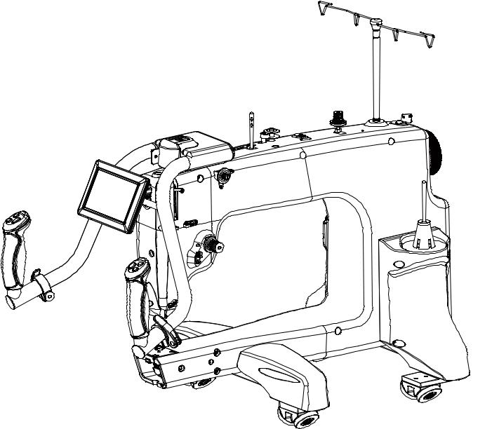
Specifications and Overview
•Height: 480 mm, 19”
•Width: 395 mm, 15.5”
•Length: 585 mm, 23”
•Weight: 42 Lbs
•Quilting Arm Length: 15” W 8.5” H
•Maximum SPM: 1800
•Minimum SPM: 90
•Input Voltage: 110-220 VAC
• Peak Power Consumption: 300 W
• Timing Belt System
• Bobbin Type: Large M Class
• 5in Touch Screen
•Custom adjustable Ergonomic Handles and Handlebars for efficiency and extended use
•Built in Bobbin Winder
•Dual Thread Tension Guides, for precise tension.
Left
Rear
Front |
Right |
5
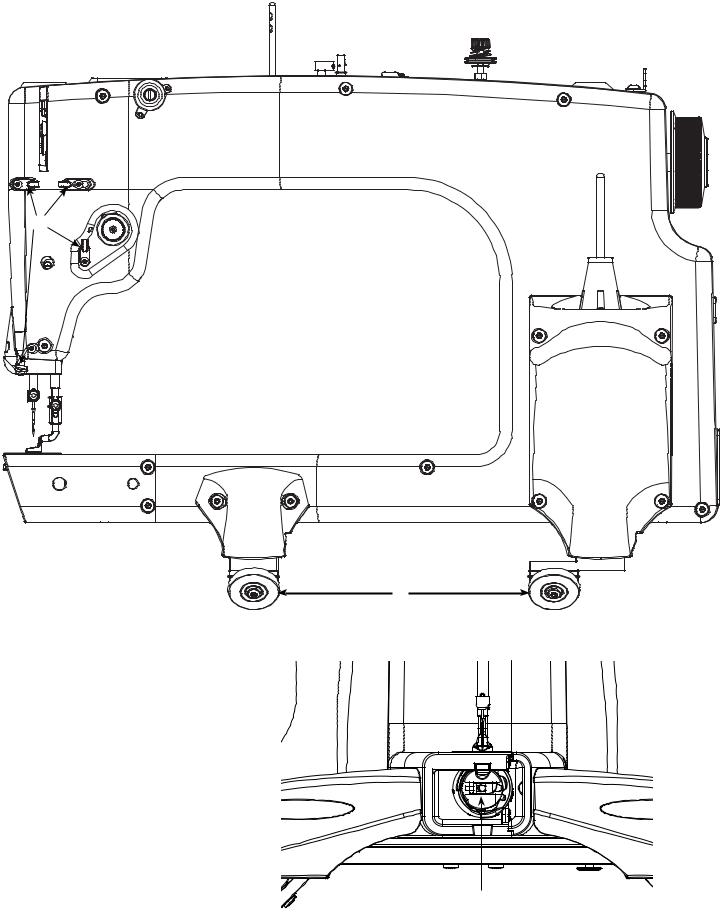
Specifications and Overview |
|
|
|||
7 |
|
3 |
|
|
|
6 |
5 |
|
|
||
4 |
1 |
2 |
|||
|
|
||||
8 |
|
|
|
||
|
|
|
|
||
11 |
|
|
|
|
|
|
9 |
10 |
18 |
|
16 |
1213 |
14 |
15 |
1. |
Thread Mast Base |
|
2. |
Bobbin Thread Guide |
17 |
3. |
Bobbin Thread Tensioner |
|
4. |
Bobbin Thread Cutter |
|
5. |
Bobbin Wind Stand |
|
6. |
Bobbin Sensor |
|
7. |
Dual Thread Tension Guide |
|
8. |
Small Thread Tensioner |
|
9. |
Large Thread Tensioner |
|
10.Thread Guides |
|
|
11.Take Up Lever |
|
|
12.Lamp |
|
|
13.Needle Bar |
|
|
14.Needle |
|
|
15.Hopping Foot |
|
|
16.Thread Stand |
|
|
17. Carriage Wheels |
|
|
18.Handwheel |
19 |
|
19.Bobbin Case |
|
|
6
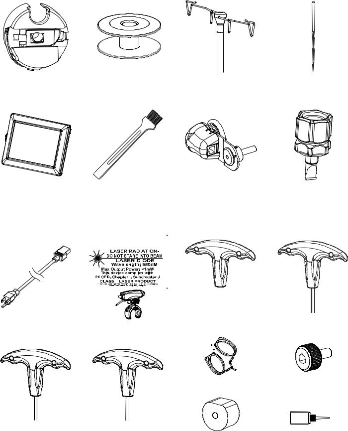
Parts List
Please make sure all pieces were included in your kit
Bobbin Case (1) |
M Class Bobbin (3) |
Thread Mast (1) |
(pre-installed) |
(2 pre-installed) |
|
5in Screen with Cable |
|
Lint Brush (1) |
Encoder (2) |
||||||||||
|
(Silver Spring - 1) |
||||||||||||
and Stylus (1) |
|
|
|
|
|
|
|
|
|
||||
|
|
|
|
|
|
|
|
|
(Black Spring - 1) |
||||
|
|
|
|
|
|
|
|
|
|
||||
|
|
|
|
|
|
|
|
|
|
|
|
|
|
|
|
|
|
|
|
|
|
|
|
|
|
|
|
|
|
|
|
|
|
|
|
|
|
|
|
|
|
|
|
|
|
|
|
|
|
|
|
|
|
|
|
|
|
|
|
|
|
|
|
|
|
|
|
|
|
|
|
|
|
|
|
|
|
|
|
|
|
|
|
|
|
|
|
|
|
|
|
|
|
|
|
|
|
|
|
|
|
|
|
|
|
|
|
|
|
|
|
|
|
|
|
|
|
|
|
|
|
|
|
|
|
|
|
|
|
|
|
|
|
|
|
|
|
|
|
|
|
|
|
|
|
|
|
|
|
|
|
|
|
|
|
|
|
|
|
|
|
|
|
|
|
|
|
|
|
|
|
|
|
|
|
|
|
|
|
|
|
|
|
|
|
|
|
|
|
|
|
|
|
|
|
|
|
|
|
|
|
|
|
|
|
|
|
|
|
|
|
|
|
|
|
|
|
|
|
|
|
|
|
|
|
|
|
|
|
|
|
|
|
|
|
|
|
|
|
|
|
|
|
|
|
|
|
|
|
|
|
|
|
|
|
|
|
|
|
|
|
|
|
|
|
|
|
|
|
|
|
|
|
|
|
|
|
|
|
Power Cord (1) |
Laser (1) |
4mm Allen Wrench (1) |
||
|
|
|
|
|
|
|
|
|
|
Encoder Springs (2)
Needle (11) (1 pre-installed)
Flat Head Screw Driver
(1)
3mm Allen Wrench (1)
M3 Thumb Screw (3)
(2 pre-installed)
2.5mm Allen Wrench (1) 2mm Allen Wrench (1) |
Timing Spacer (1) |
Oil Bottle (1) |
7
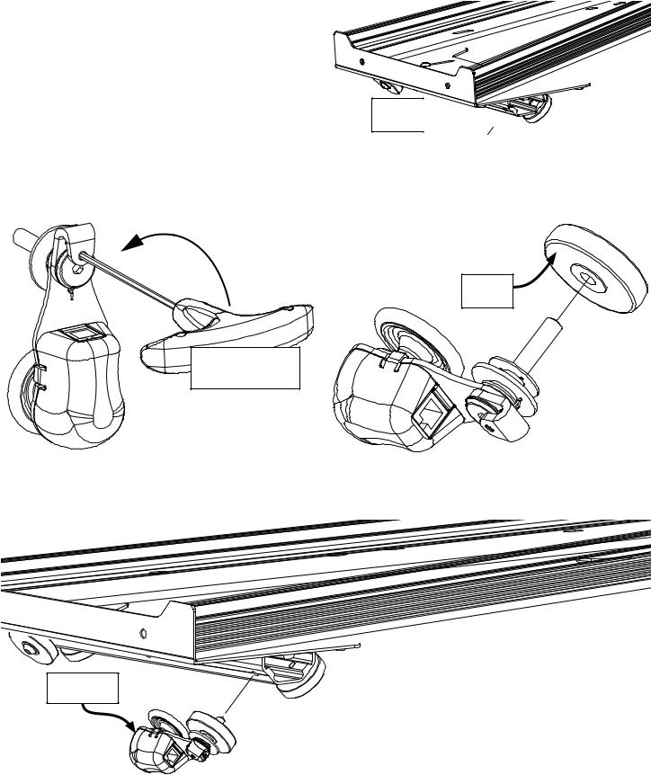
Step 1: Installing the Encoder on the Carriage
Parts Needed:
1.Encoder (1) (1 black spring)
2.2mm Allen Wrench (1)
3.4mm Allen Wrench (1)
1-1 Remove the M6 x 16mm SBHCS from the outer, left, rear wheel, on the Bottom
Plate.
Wheel 

1-2 Loosen the set screw in the lock collar, without removing it, so that the encoder wheel bolt can turn freely.
1-3 Slide the previously removed wheel onto the encoder with hub side out.
Wheel
Loosen The Set Screw Using The
2mm Allen Wrench
1-4 Fasten the encoder into the hole made available in step 1-1.
Note: Leave the encoder’s set screw loose. They will be tightened after you place the sewing machine on your frame.
Encoder With
Black Spring
8
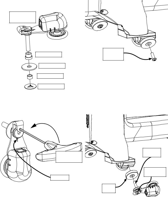
Step 2: Installing the Encoder on the Quilting Machine
Parts Needed:
1.Encoder (1) (1 Silver Spring)
2.2mm Allen Wrench (1)
3.4mm Allen Wrench (1)
Encoder Assembly
Shoulder Spacer
Washer
Wheel Spacer
Plastic Stop
2-1 Remove the M6 x 16mm SBHCS from the outer, left, rear wheel, on the sewing machine.
Remove the
M6 x 16mm
SBHCS
2-2 Loosen the set screw in the lock collar, so |
2-3 Slide the previously removed wheel |
that the encoder wheel bolt can turn freely. |
onto the encoder and the hole made |
|
available in step 3-1. |
|
Note: Leave the encoder’s set screw loose. They |
|
will be tightened in a later step. |
Loosen The |
Set |
Encoder |
|
Wheel Bolt |
|||
Screw Using The |
|||
|
|||
2mm Allen Wrench |
|
||
|
|
Encoder with |
|
Silver Spring |
|
Silver Spring |
|
|
|
||
|
|
Wheel |
|
9
|
|
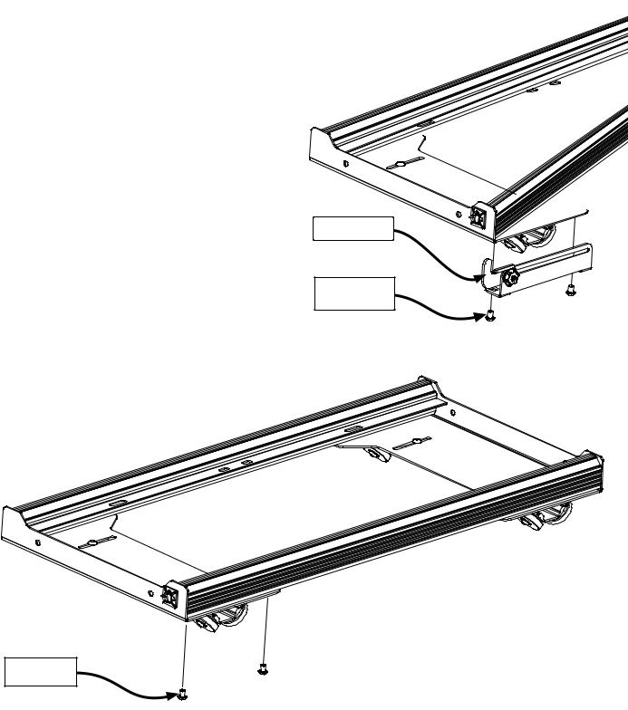
Step 3: Bottom Plate |
Parts Needed: |
3-1 Remove Carriage stop from bottom |
|
1. |
4mm Allen Wrench |
|
2. |
Bottom Plate |
plate, by removing (2) M6 X 10 mm SBHCS. |
Carriage Stop
M6 x 10mm
SBHCS
3-1 Re-install the (2) M6 X 10 mm SBHCS removed in step 3-1.
M6 x 10mm
SBHCS
10

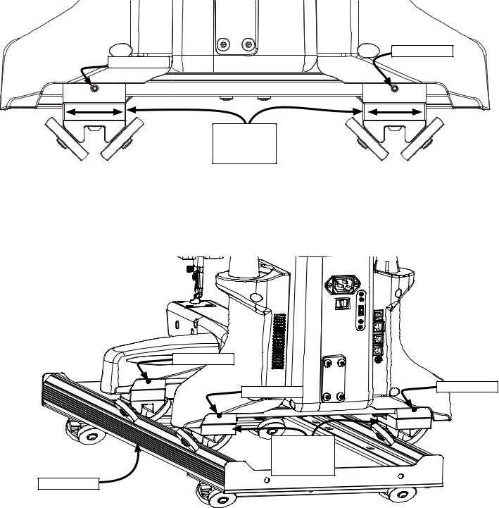
Step 4: Carriage and encoders
3-1 Place the bottom plate onto the quilting frame.
3-3 Plug the encoder cables from each of the encoders into the sewing machine.
Note: The longer cable is used for the encoder attached to the carriage, while the shorter cable is used for the encoder attached to the sewing machine.
3-2 Place the sewing machine onto the bottom plate. Raise Back Rail on Frame to be 1/4” above the machine base.
3-4 Rotate the lock collar on the encoder up about 100 degrees or until you feel adequate push back from the spring. While holding the lock collar in that position, tighten each set screw.
Encoder Spring Tensioning
|
|
|
|
|
|
Lock Collar |
|
|||
|
|
|
|
|
|
|
|
|
|
|
|
100 degrees |
|
|
|
|
|
Top Encoder/ |
|||
|
|
up |
|
|
|
|
|
Silver Spring |
||
|
|
|
|
|
|
|
|
|
|
|
|
|
|
|
|
|
|
|
|
|
|
|
|
|
|
|
|
|
|
|
|
|
Set Screw
Long Encoder |
Short Encoder |
Cable |
Cable |
Bottom Encoder/ |
|
100 degrees |
Black Spring |
|
up |
QR CODE |
Lock Collar |
|
11
Step 4: Wheel Alignment
Parts Needed:
1.3mm Allen Wrench (1)
4-1 Using the 3mm allen wrench, loosen the set screws located above each of the wheels on the machine.
M6 Set Screw
M6 Set Screw |
Wheel
Assemblies
4-2 Re-adjust the wheels as necessary while centering the machine between the left and right wheels and tighten the set screws. Make sure that the encoders ride on the track.
M6 Set Screw
M6 Set Screw |
M6 Set Screw |
|
Wheel
Assemblies
Carriage
12
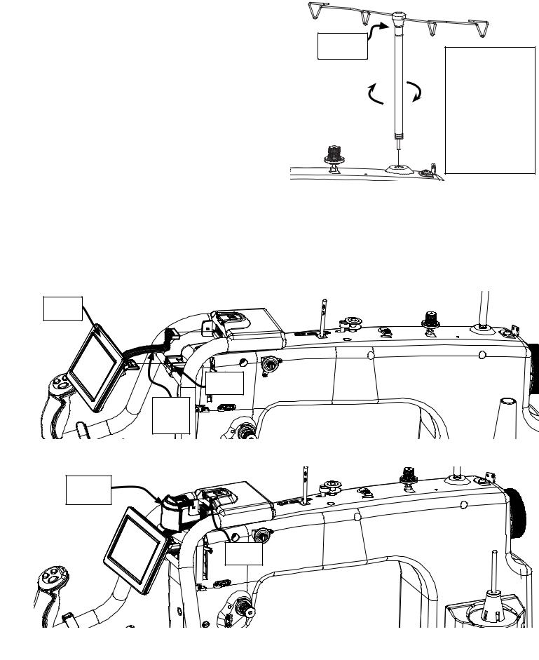
Step 5: Attaching the Thread Mast
Parts Needed: |
5-1 Screw the Thread mast to the Sewing |
||
1. |
Thread Mast (1) |
Machine. |
|
|
|
Thread |
|
|
|
Mast |
The thread |
|
|
|
|
|
|
|
mast acts as a |
|
|
|
guide for the |
|
|
|
thread, and |
|
|
|
makes it less |
|
|
|
likely to get |
|
|
|
snagged or |
|
|
|
looped around |
|
|
|
any object. |
Step 6: Connecting the Front Display
Parts Needed:
1.Display Screen (1) (with cable and clip)
2.Screen Mount Cap (1)
6-1 Connect the Display ribbon cable from the Display to the display mount, and attach the display by snapping it into the Display Clip.
Display
Screen
Display
Clip
Display
Ribbon
Cable
6-2 Attach Screen Mount Cap into the Display Hub.
Screen
Mount Cap
Display
Hub
13
 Loading...