

Page 1

Instruction Manual
Personal Embroidery Design Software System
Before using this software, first read the Installation Guide for details on installing the software.
In addition, be sure to read this Instruction Manual before using the software.
We recommend that you keep this document nearby for future reference.
Page 2

Congratulations on choosing our product!
Thank you very much for purchasing our product. To obtain the best performance from this device and to
ensure safe and correct operation, please read this Instruction Manual carefully, and then keep it in a safe
place together with your warranty.
Please read before using this product
For designing beautiful embroidery designs
• This system allows you to create a wide variety of embroidery designs and supports a wider range of
sewing attribute settings (thread density, sewing pitch, etc.). However, the final result will depend on your
particular embroidery machine model. We recommend that you make a trial sewing sample with your
sewing data before sewing on the final material.
For safe operation
• Do not save any files on the "PE-DESIGN Software Key" for transferring or storage.
• Do not plug the "PE-DESIGN Software Key" into your embroidery machine.
For a longer service life
• When storing the "PE-DESIGN Software Key", avoid direct sunlight and high humidity locations. Do not
store the "PE-DESIGN Software Key" close to a heater, iron or other hot objects.
• Do not spill water or other liquids on the "PE-DESIGN Software Key".
• Do not drop or hit the "PE-DESIGN Software Key".
For repairs or adjustments
• In the event that a malfunction occurs or adjustment is required, please consult your nearest service
center.
Notice
• Since this "PE-DESIGN Software Key" device is required to run the software, its replacement value is
the retail price of the software. Please keep in a safe place when not in use.
• Neither this Instruction Manual nor the Installation Guide explains how to use your computer under
Windows
• The procedures in this manual are written for use in Windows
operating system other than Windows
slightly.
®
. Please refer to the Windows® manuals.
®
10, the procedures and appearance of the windows may differ
®
10. If this software is used on an
Trademarks
• Windows® is a registered trademark of Microsoft Corporation.
• CorelDRAW
Canada, the United States and/or other countries.
• Adobe
in the United States and/or other countries.
• Other product names mentioned in the Instruction Manual and Installation Guide may be trademarks of
registered trademarks of their respective companies and are hereby acknowledged.
®
is a trademark or registered trademark of Corel Corporation and/or its subsidiaries in
®
and Illustrator® are either registered trademarks or trademarks of Adobe Systems Incorporated
Caution
The software included with this product is protected by copyright laws. This software can be used or copied
only in accordance with the copyright laws.
SAVE THESE INSTRUCTIONS
This product is intended for household use.
For additional product information and updates, visit our website at:
http://www.brother.com/ or http://support.brother.com/
1
Page 3
Search by Sample Project
Making a Quilt Using an
Embroidery Pattern
cc page 14
Arranging Stitch Patterns
cc page 21
Changing the Stitching for
Each Shape Pattern
cc page 24
Creating Embroidery
Patterns From a Vector File
cc page 40
2
Page 4
Editing an Imported Shape
Combining Text
to Create an Embroidery
Design for an Appliqué
cc page 27
Auto Punch
cc page 73
cc page 64
Cross Stitch
cc page 76
Photo Stitch1
cc page 79
Photo Stitch2
cc page 84
3
Page 5
Search by Operation
Visualizing the finished project
I want …
Creating patterns
I want …
Arranging patterns
I want …
• a sample project that I can follow.
cc page 14, 21, 24, 27, 40, 64, 73, 93
• to see various sample patterns.
cc page 44, 64
• to embroider an image file that I have.
cc page 40, 90
• to enter text.
cc page 67
• to use a photo or illustration.
cc page 40, 90
• to move patterns.
cc page 21, 53
• to enlarge/reduce patterns.
cc page 54
• to rotate patterns.
cc page 54
• to enjoy arranging patterns.
cc page 21, 53
Adding colors
• to change color combination.
cc page 61
• to simulate color schemes.
cc page 61
I want …
4
Page 6
Enhancing with sewing
attributes
I want …
• to change the sew types for patterns.
cc page 24, 62
• to make the pattern more expressive.
cc page 62
Creating embroidery data
I want …
Embroidering
I want …
• to know what I can do with the data.
cc page 28, 34
• to preview the finished embroidery.
cc page 35, 36
• to choose the sewing order.
cc page 37
• to embroider with my embroidery machine.
cc page 18, 19
• to save my favorite designs.
cc page 46
• to manage embroidery data I create.
cc page 46, 59
5
Page 7
Table of Contents
Search by Sample Project.............. 2
Search by Operation....................... 4
Table of Contents ........................... 6
PE-DESIGN Software Key .............. 7
Comparison of Types of Data
Created With
PE-DESIGN PLUS2 ......................... 8
Starting Up Applications................ 9
Understanding Windows.............. 10
PE-DESIGN PLUS2 Window.......................... 10
Example of Importing Embroidery Data.......... 13
Basic Operations .......................... 14
Tutorial 1: Making a Quilt Using an Embroidery
Pattern ............................................................ 14
Tutorial 2: Arranging Stitch Patterns............... 21
Tutorial 3: Changing the Stitching for Each
Shape Pattern................................................. 24
Tutorial 4: Editing an Imported Shape to Create
an Embroidery Design for an Appliqué ........... 27
Specifying the Design Page Settings.............. 32
Checking Embroidery Patterns ....................... 34
Tutorial 5: Creating Embroidery Patterns From
a Vector File.................................................... 40
Opening/Importing Embroidery Designs......... 43
Saving and Exiting .......................................... 46
Printing............................................................ 47
Drawing Shapes and Reshaping .................... 49
Editing Embroidery Designs............................ 53
Specifying Thread Colors and Sew Types for
Lines and Regions .......................................... 61
Creating Embroidery Patterns
Using Images ................................ 73
Tutorial 7-1: Auto Punch ................................. 73
Tutorial 7-2: Cross Stitch.................................76
Tutorial 7-3: Photo Stitch 1..............................79
Tutorial 7-4: Photo Stitch 2..............................84
Advanced Stitch Wizard Operations ...............87
Importing and Editing Image Data...................90
Creating Design for Multi-Position
Hoops............................................. 93
Tutorial 8: Creating Design for Multi-Position
Hoops.............................................................. 93
Supplement ................................... 98
Changing Various Settings..............................98
For Basic Operations .................................... 104
Reference .................................... 106
Sewing Attributes ..........................................106
Font List ........................................................ 110
Troubleshooting ............................................ 112
Support/Service.............................................114
Index ............................................ 116
Creating Embroidery Patterns
Containing Text............................. 64
Tutorial 6: Combining Text.............................. 64
Advanced Operations for Entering Text.......... 67
6
Page 8
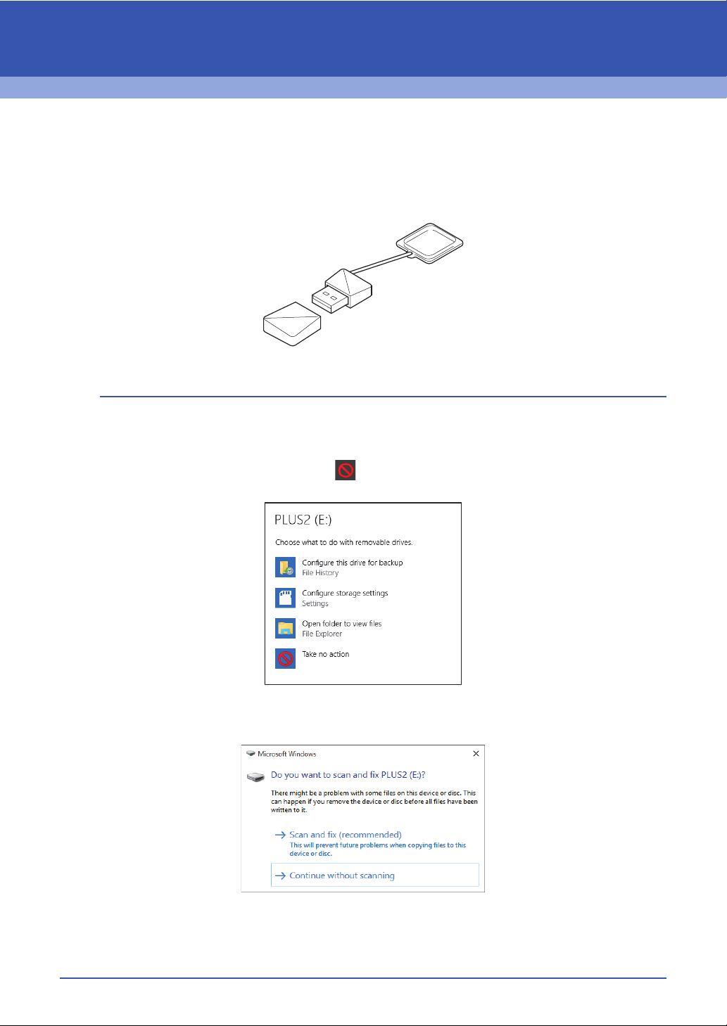
PE-DESIGN Software Key
In order to use PE-DESIGN PLUS2, the included "PE-DESIGN Software Key" must be plugged into a USB
port of the computer.
The "PE-DESIGN Software Key" prevents unauthorized use of this software. The software cannot be started
if the "PE-DESIGN Software Key" is not plugged in.
* Design is subject to change.
a
• The "PE-DESIGN Software Key" cannot be used as USB media. Do not save embroidery files on the "PEDESIGN Software Key" for transferring or storage.
• When the "PE-DESIGN Software Key" is plugged into a USB port of the computer, the [AutoPlay] dialog
box appears. Do not use this dialog box. Click to close the dialog box, and then start up PE-DESIGN
PLUS2.
• When the message "Do you want to scan and fix PLUS2 (E:)?" appears, select [Continue without
scanning] and then start up PE-DESIGN PLUS2. The drive name for the PLUS2 differs depending on
computers.
• To unplug the "PE-DESIGN Software Key" from the computer, click [Start] - [File Explorer], right-click the
"PE-DESIGN Software Key", and then click [Eject].
• Do not format the "PE-DESIGN Software Key".
• We recommend that you back up this software in order to prepare for unexpected problems.
7
Page 9
Comparison of Types of Data Created
With PE-DESIGN PLUS2
Three types of data are used in PE-DESIGN PLUS2.
Stitch pattern: Most of built-in embroidery data
Text pattern: Data created with the [Text] tools
Shape pattern (Outline pattern): Data created with the [Shapes] tools.
■ Stitch pattern
Stitch patterns can be arranged by rotating, flipping over and combining them.
■ Text pattern
You can edit text by entering/deleting characters, specify text attributes (such as the font or the
transformation shape) and specify sewing attributes.
■ Shape pattern
You can specify region and line sew types as well as sewing attributes, edit paths (by moving/deleting
points, reshaping through handle movements), remove/merge overlapping regions, set hole sewing, and
create offset lines.
8
Page 10
Starting Up Applications
abcg
def j i
h
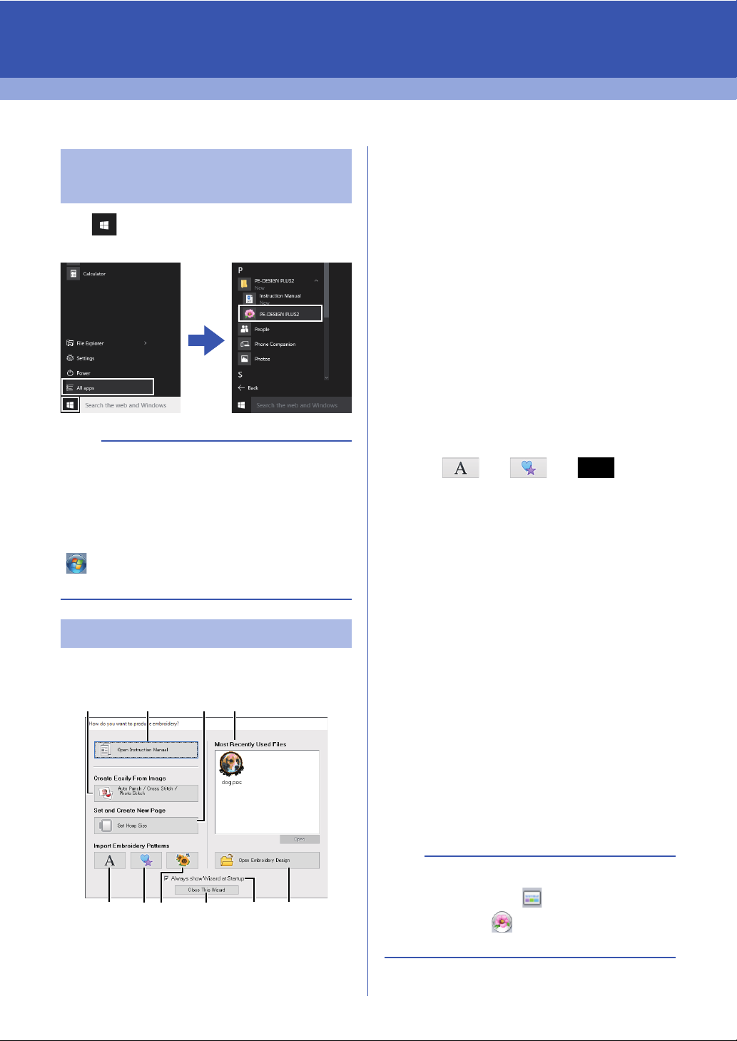
Starting up PE-DESIGN
PLUS2
Click , then [All apps], then [PE-DESIGN
PLUS2], and then click [PE-DESIGN PLUS2].
b
For Windows® 8.1 users: Click the down arrow in
the bottom-left corner of the [Start] screen to show
the [Apps] view, and then Click [PE-DESIGN
PLUS2] under the title [PE-DESIGN PLUS2] in
the screen.
®
For Windows
, then [All Programs], then [PE-DESIGN
PLUS2], and then click [PE-DESIGN PLUS2].
About the Startup Wizard
When [PE-DESIGN PLUS2] starts up, the following
wizard appears.
7 or Windows Vista® users: Click
a Open Instruction Manual
Click this button to open the Instruction
Manual (in PDF format).
b Auto Punch / Cross Stitch / Photo
Stitch
Click this button to start the wizard for
creating an embroidery pattern from an
image.
cc "Creating Embroidery Patterns Using
Images" on page 73 and "Importing
and Editing Image Data" on page 90
c Set Hoop Size
Click this button to specify the size of the
Design Page (embroidery hoop size).
cc "Specifying the Design Page
Settings" on page 32
d , e , f
Click these buttons to import the pattern
shown on the button from the [Import]
pane.
g Most Recently Used Files
Click the name of a file from the list, and
then click [Open].
h Open Embroidery Design
Click this button to open embroidery data
(.pes).
cc "Opening a PE-DESIGN PLUS2 file"
on page 43
i Always show Wizard at Startup
Select this check box to start up the
wizard each time PE-DESIGN PLUS2 is
started up.
j Close this Wizard
Click this button to close the Startup
Wizard without performing an operation.
b
To open the wizard while you are using the [PE-
DESIGN PLUS2], click in the [Quick Access
Toolbar], or click and then select [Wizard]
from the command menu.
9
Page 11
Understanding Windows
14
15
12
1
7
8
9
13
2
6
11
45
10
3
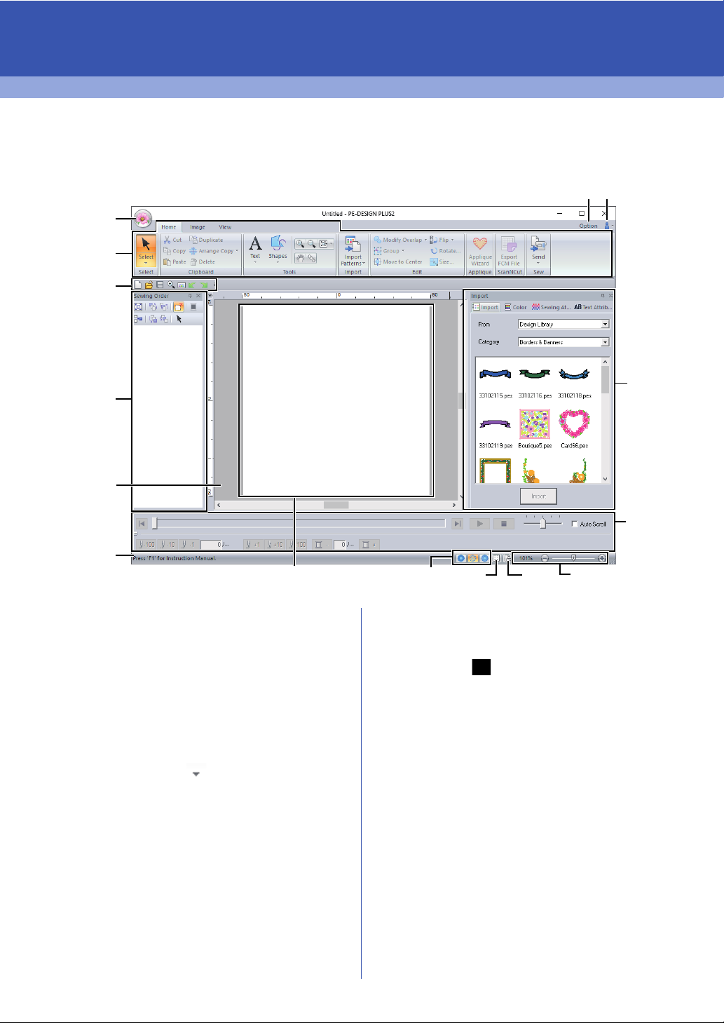
PE-DESIGN PLUS2 Window
1 Application button
Click to display a menu containing commands
for file operations, such as [New], [Save],
[Print] and [Design Settings].
2 Ribbon
Click a tab at the top to display the
corresponding commands.
Refer to the name below each group when
selecting the desired command. Clicking a
command with the mark displays a menu
containing a choice of commands.
3 Quick Access Toolbar
This contains the most frequently used
commands. Since this toolbar is always
displayed, regardless of the Ribbon tab that is
selected, adding your most often used
commands makes them easily accessible.
cc "Customizing Quick Access Toolbar" on
page 98
4 Option button
Click this button to specify settings for the
Design Page and user thread charts.
5 Help button
Click this button to display the Instruction
Manual and view information about the software.
6 Sewing Order pane
This pane shows the sewing order. Click the
buttons at the top of the pane to change the
sewing order or thread color.
7 Import/Color/Sewing Attributes/Text
Attributes panes
This pane combines tabs for importing
embroidery patterns as well as for specifying
thread colors, sewing attributes and text
attributes. Click a tab to display the available
parameters.
8 Stitch Simulator pane
The Stitch Simulator shows how the pattern will
be sewn by the machine and how the stitching
will appear.
10
Page 12
Understanding Windows
9 Design Page
The actual part of the work area that can be
saved and sewn.
10 Work area
11 Status Bar
This displays the size of the embroidery data,
the number of stitches or a description of the
selected command.
12 View mode buttons
Click a button to change the View mode.
13 Show grid button
Click to switch between displaying and hiding
the grid.
14 Design Property button
Click to display a dialog box containing sewing
information for the embroidery data.
15 Zoom slider
This displays the current magnification ratio.
Click to specify a value for the magnification
ratio.
Drag the slider to change the magnification ratio.
b
• Panes 6, 7 and 8 can be displayed or hidden
from the [Show/Hide] group in the [View] tab. In
addition, these panes can be displayed as
separate dialog boxes (Floating) or attached to
the main window (Docking).
• Position the pointer over a command to display
a ScreenTip, which provides a description of the
command and indicates its shortcut key.
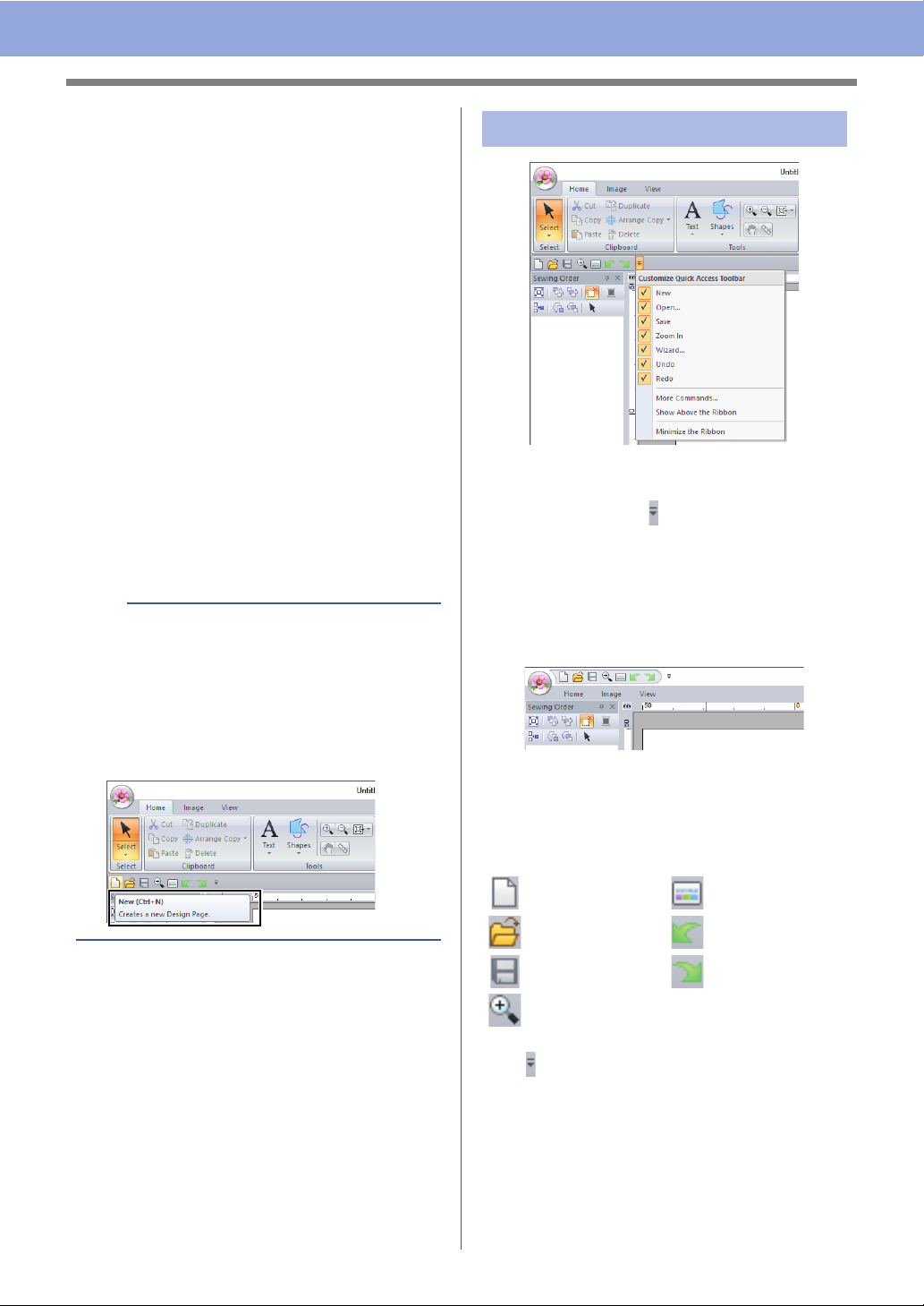
Customizing the window
■ Quick Access Toolbar/Ribbon
A menu appears when in the [Quick Access
Toolbar] is clicked.
The menu contains various commands, such as
[Show Above the Ribbon] and [Minimize the
Ribbon], to customize the window.
Example: With [Show Above the Ribbon] selected
and a check mark beside [Minimize the Ribbon]
■ Quick Access Toolbar commands
The first time this application is started up, the
following commands appear in the Quick Access
Toolbar.
: New : Wizard
: Open : Undo
: Save : Redo
: Zoom In
Click , then select or unselect the check boxes
beside the commands to switch between displaying
and hiding them. When the check mark is cleared,
the command is hidden. Alternatively, changes to
the commands listed in the [Quick Access
Toolbar] can be specified in the [Options] dialog
box and all applied at the same time.
cc "Customizing Quick Access Toolbar" on
page 98
11
Page 13
Understanding Windows
■ Import/Color/Sewing Attributes/
Text Attributes pane, Sewing
Order pane and Stitch Simulator
pane
Floating
Each tab or the entire pane can be undocked to
become a dialog box that can be moved around the
screen.
• Double-click the title bar of the pane, or tab.
• Right-click the pane or tab, and then click
[Floating].
• Drag a tab out of the pane.
Docking
Each pane can be docked back to the window.
• Double-click the title bar.
• Right-click the pane, and then click [Docking].
• Drag the title bar to the location where the pane
will be docked.
Hide
When a tab or a pane is no longer needed, it can be
hidden.
• Click in the upper-right corner of the dialog
box.
• Right-click the tab or dialog box, and then click
[Hide].
• To hide the tab, click [View] tab in the Ribbon,
and then click the name in the [View] tab. To
display the tab again, perform the same
operation.
Auto Hide
When a pane is temporarily not needed, it
can be moved to the side bar, then
displayed by clicking it or positioning the
pointer over it. The pane is automatically
hidden again when it is no longer being
used, for example, when you click
anywhere outside of the pane.
• Right-click the tab or the title bar of the pane, and
then click [Auto Hide].
• In the upper-right corner of the pane, click .
To cancel Auto Hide, right-click the title bar, and
then click [Auto Hide], or simply click in the title
bar.
b
• The Stitch Simulator pane cannot be temporarily
hidden (Auto Hide).
• These panes can be returned to their default
displays.
cc "Customizing Shortcut keys" on page 99
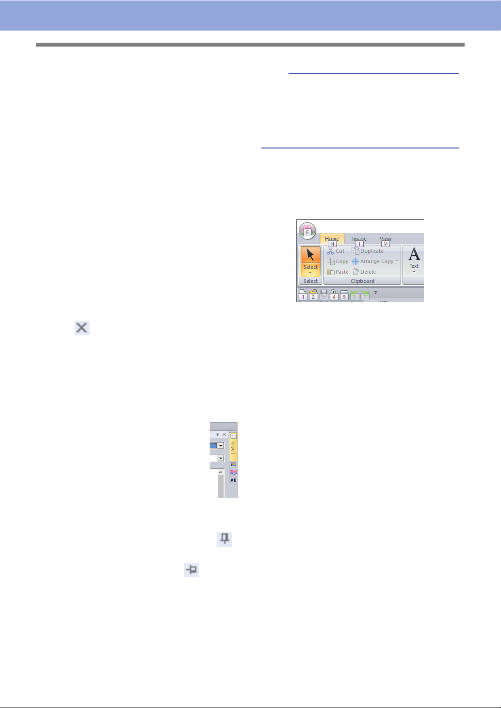
■ Using access keys
When the <Alt> key is pressed, a KeyTip (label
showing the letter of the access key) appears on
each command. On the keyboard, press the key
corresponding to the command that you wish to use.
To stop using the access keys and hide the
KeyTips, press the <Alt> key.
12
Page 14
Understanding Windows
a
b
c
d
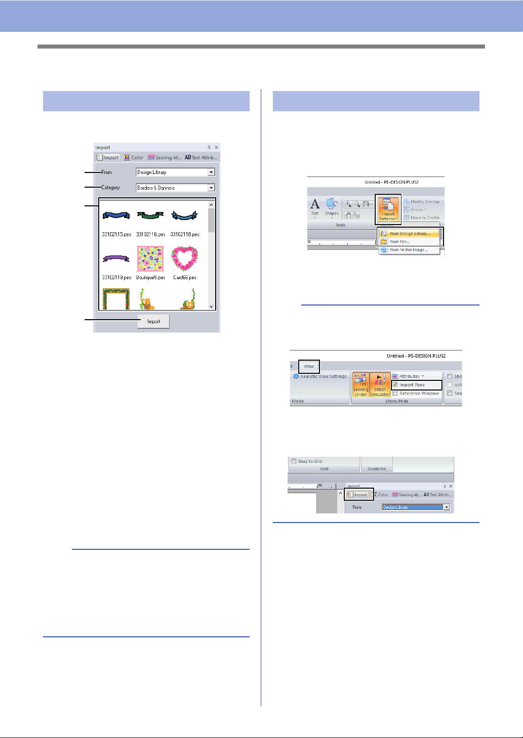
Example of Importing Embroidery Data
Using the Import pane
Embroidery data can be imported by using the
[Import] pane.
a From
Select a pattern location.
b Category
Select a pattern category.
The categories in the pattern location
selected in the [From] selector are listed.
c The patterns in the category selected in
the [Category] selector appear in the list.
Pointing to a pattern and holding down the
left mouse button displays a dotted box in
the Design Page. This allows you to
check the size of the pattern.
d Import
Click this button to import the selected
pattern.
Using Import commands
1 Click the [Home] tab.
2 Click [Import Patterns] in the [Import] group,
and then click [from Design Library] or [from
File] from the [Import] menu.
The [Import] pane appears on the right
side of the screen.
b
The [Import] pane can also be displayed by
selecting the [Import Pane] check box in the
[View] tab.
When the [Color] pane, [Sewing Attributes]
pane or [Text Attributes] pane is displayed, click
the [Import] tab to display the [Import] pane.
b
• The pattern can also be imported by
double-clicking it in the list or by dragging it to
the Design Page.
• Multiple files cannot be selected to be imported
at the same time.
cc "From a folder" on page 44
13
Page 15
Basic Operations
Tutorial 1: Making a Quilt Using an Embroidery Pattern
This section will describe how to create an embroidery pattern for quilting. We will use the Shapes tools to
draw lines for positioning fabric and for stitching. This data will then be transferred to an embroidery machine
in order to make a quilt.
The sample file for this tutorial is located at:
Documents (My documents)\PE-DESIGN PLUS2\Tutorial\Tutorial_1
Step 1 Importing image data into PE-DESIGN PLUS2
Step 2 Changing the grid settings
Step 3 Scaling an image
Step 4 Adjusting the density of the background image
Step 5 Drawing straight lines for positioning fabric
Step 6 Drawing straight lines for stitching fabrics with right sides together
Step 7 Transferring embroidery patterns to embroidery machines
Step 8 Quilting with the machine
Step 1 Importing image data into
PE-DESIGN PLUS2
1 Click the [Image] tab.
b
When this application is installed, the [PEDESIGN PLUS2] folder is installed in the
Documents folder.
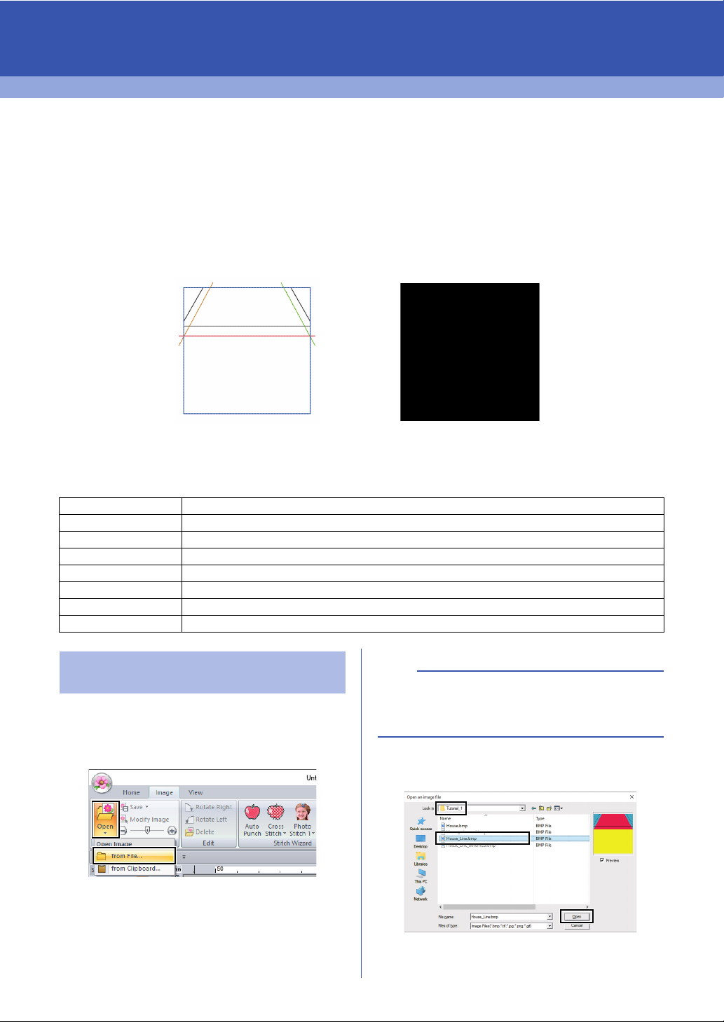
2 Click [Open] in the [Image] group, and then
click [from File].
4 Select the file [House_Line.bmp], and then
click [Open], or double-click the file's icon.
3 Double-click the [Documents (My
documents)\PE-DESIGN PLUS2\Tutorial\
Tutorial_1] folder to open it.
The image appears in the work area.
14
Page 16
Tutorial 1: Making a Quilt Using an Embroidery Pattern
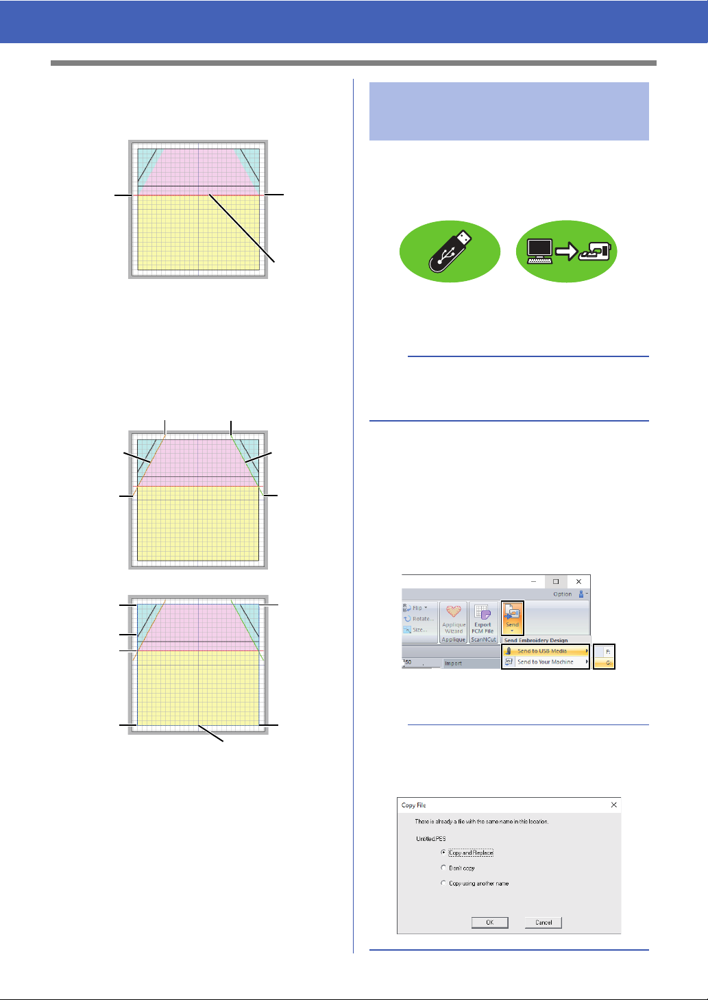
1
2
a
b
d
c
1 Handle
2 Red line
b
• This image was created by adding lines,
separated by the width of the seam allowance,
to the outside of the shapes in the illustration of
the house.
• To create a similar quilt:
- First, print the design.
- Draw lines (for the seam allowances) about
7 mm from each of the shapes in the design.
- Scan the image, save it to a computer, and
then import it into PE-DESIGN PLUS2 as a
background image.
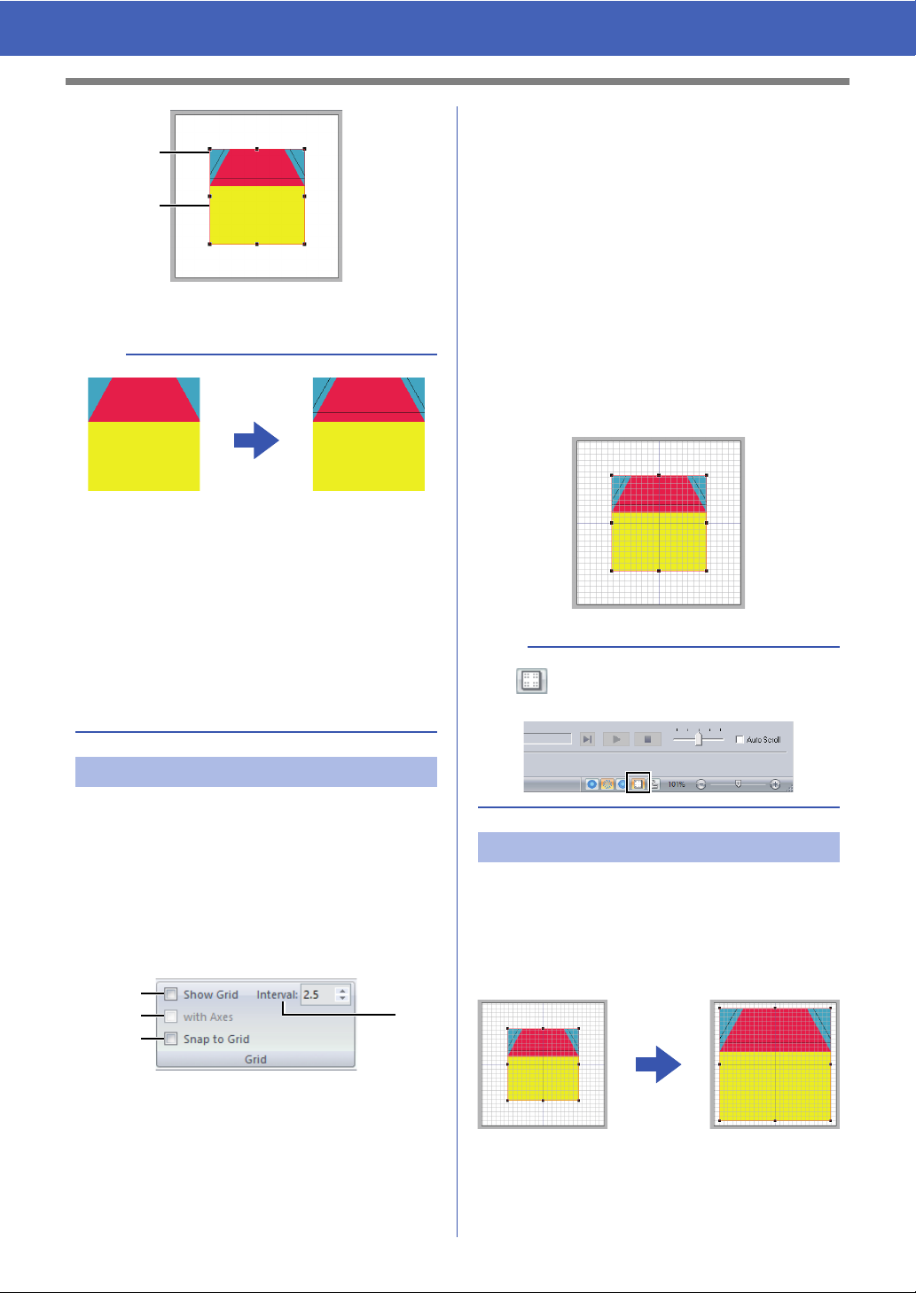
b with Axes
Select this check box to display the grid as
solid lines.
For this example, select this check
box.
c Interval
Specify the grid spacing.
For this example, set [Interval] to 3.5
mm.
d Snap to Grid
Select this check box to align patterns
with the grid. The snap feature works
whether or not the grid is displayed.
For this example, select this check
box.
b
The button can also be used to switch the
grid between being displayed or hidden.
Step 2 Changing the grid settings
Use the grid settings to draw lines for positioning the
fabric.
A grid of dotted lines or solid lines can be displayed
or hidden, and the spacing for the grid can be
adjusted.
1 Click [View] tab.
2 Specify the grid settings.
a Show Grid
Select this check box to display the grid.
For this example, select this check
box.
Step 3 Scaling an image
1 Drag the handle to adjust the image to the
desired size.
Enlarge the image to the maximum size of
about 95 mm square and position it with the
corners of its outline at intersections of the
grid.
15
Page 17
Tutorial 1: Making a Quilt Using an Embroidery Pattern
Hide (off)
50%
25%
75%
100%
1
12
34
56
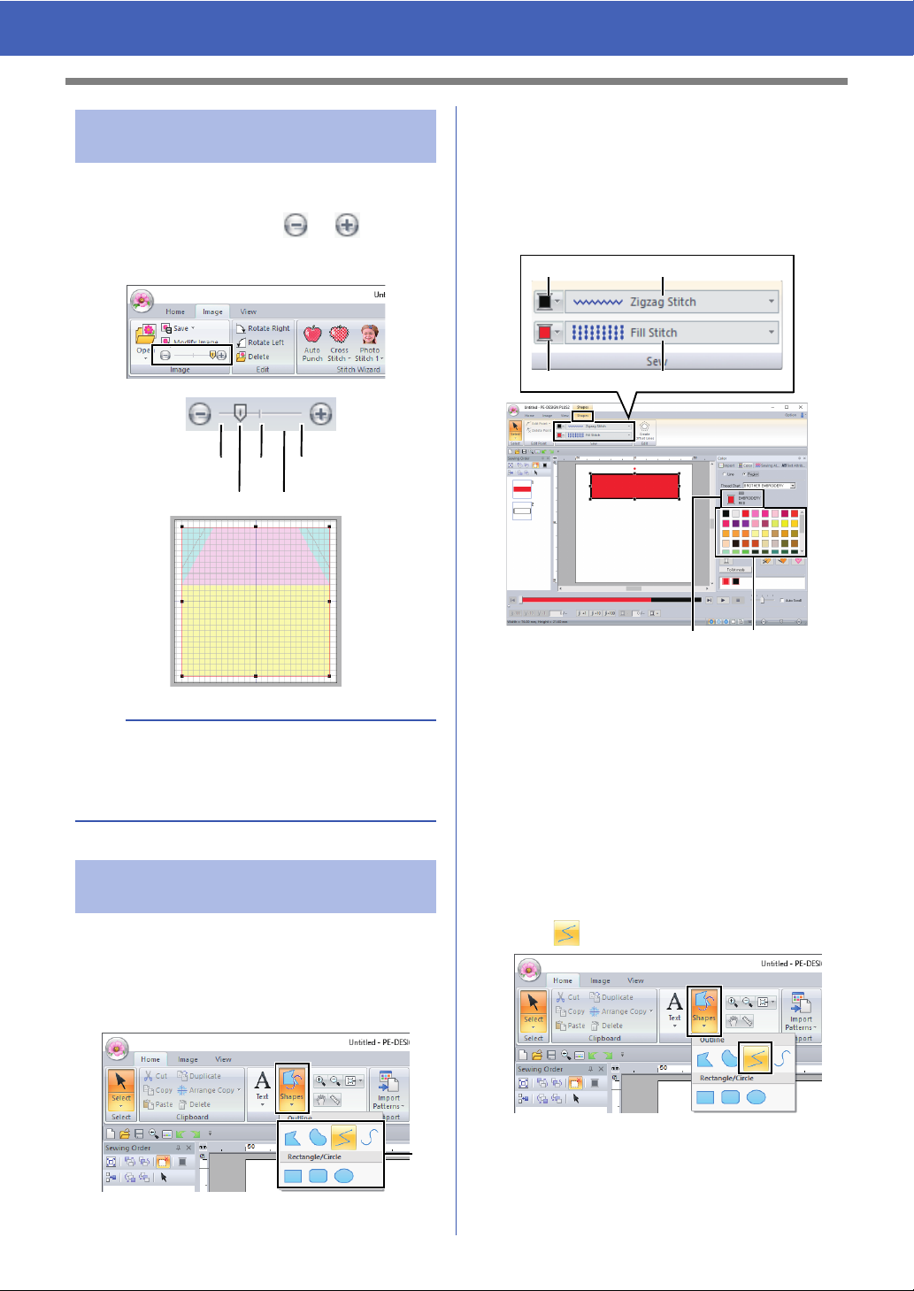
Step 4 Adjusting the density of
the background image
1 Click the [Image] tab.
2 Drag the slider, or click or in the
[Image] group to change the density of the
template image to "25%".
Specify the sew types for the shape on the [Shapes]
tab, and the thread colors on the [Shapes] tab or the
[Color] pane.
The screen changes so that the sew types and
thread colors for the shape can be specified. The
thread colors can also be specified on the [Color]
pane.
b
Press the shortcut key <F6> to switch between
displaying the image (On (100%)) to displaying it
faded at each density (75%, 50% and 25%) to
hiding the image (Off).
Step 5 Drawing straight lines for
Shapes can be created either by drawing them with
the Shapes tools.
To draw a shape, select a Shapes tool, and then
drag the pointer in the Design Page to draw the
shape.
positioning fabric
1 Line color button
2 Line sew type selector
3 Region color button
4 Region sew type selector
5 Selected thread color and color name
6 Thread color palette
Draw straight lines as reference for positioning the
fabric.
1 Click the [Home] tab.
2 Click [Shapes] in the [Tools] group, and then
click in the Shapes tools.
1 Shapes tools
16
Page 18
Tutorial 1: Making a Quilt Using an Embroidery Pattern
e
d
f
a
c
b
g
h
j
i
k
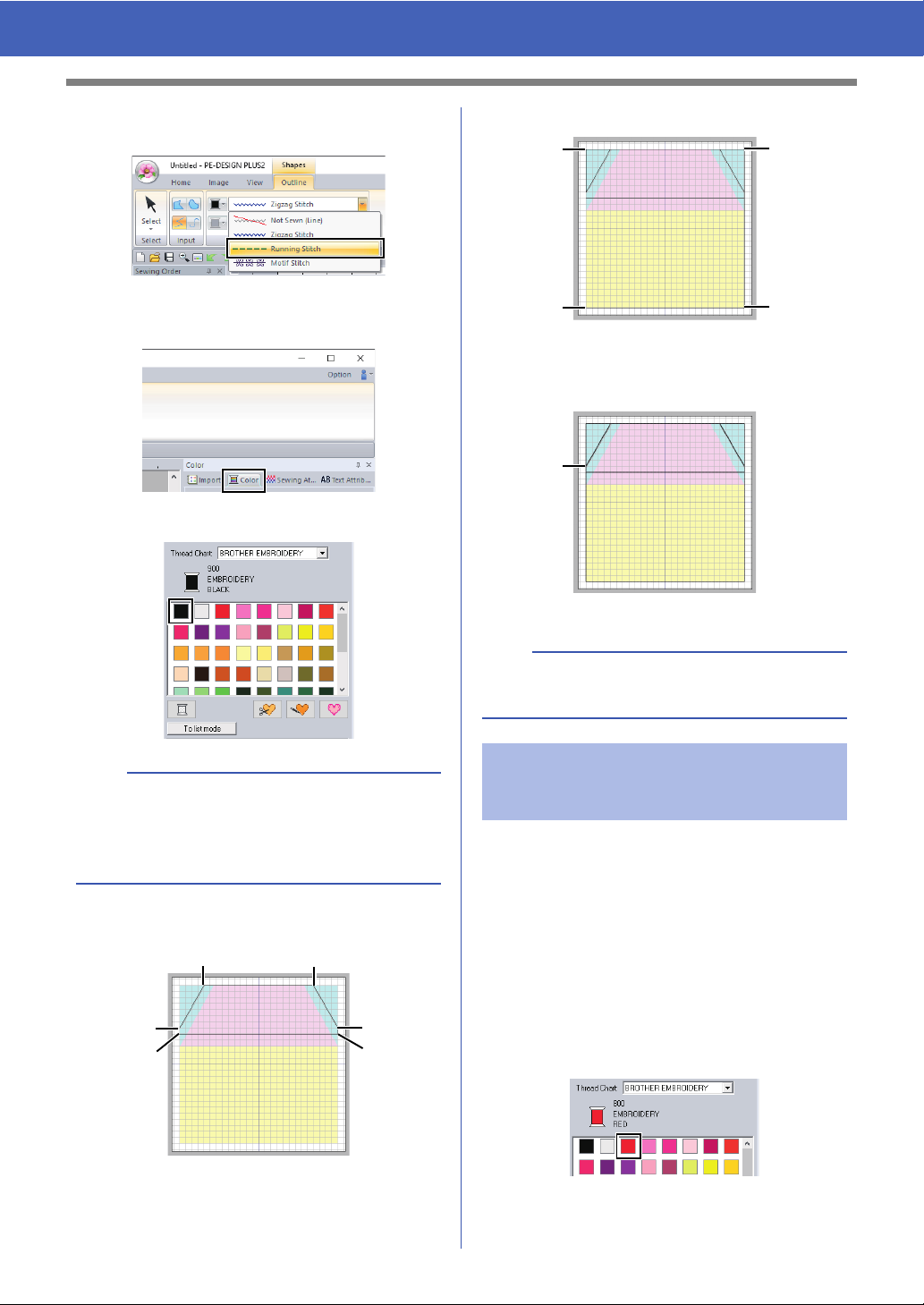
3 Click the [Line sew type] selector, and then
select [Running Stitch].
4 Click the [Color] tab to display the color
palette.
5 Click [BLACK].
7 Double-click end point k.
b
To view the thread colors in a list so that the
desired color can more easily be found, click [To
list mode].
cc "Setting the thread color" on page 61
6 Click points a through j.
b
The color, sewing attributes and size can also be
changed after the shape is drawn.
Step 6 Drawing straight lines for
stitching fabrics with right
sides together
We will draw lines at the positions where the
machine will sew. The machine will sew the fabric in
the order that the lines are drawn.
A different color must be specified for each line.
1 Repeat 1 through 4 under "Step 5 Drawing
straight lines for positioning fabric" on
page 16.
2 Specify a line color different from what is
already selected.
For this example, select [RED].
17
Page 19
Tutorial 1: Making a Quilt Using an Embroidery Pattern
a
b
Line (1)
e
c
f
d
Line (2)Line (3)
k
j
h
i
l
g
Line (4)
3 Click point a, and then double-click end point
b to draw line (1).
4 Repeat the previous steps to draw lines (2),
(3) and (4).
For this example, select [LIME GREEN] for
line (2), [PUMPKIN] for line (3), and [BLUE]
for line (4).
Step 7 Transferring embroidery
patterns to embroidery
machines
You can sew a pattern transferred to your
embroidery machine by writing it to media.
For details, refer to the Operation Manual provided
with your embroidery machine.
Designs can be transferred to an embroidery
machine compatible with USB media or connected
to a computer using a USB cable.
a
The "PE-DESIGN Software Key" cannot be used
as USB media. Do not save embroidery files on
the "PE-DESIGN Software Key" for transferring.
1 Plug the USB media into the computer, or
connect the embroidery machine to the
computer.
2 Click the [Home] tab.
3 Click [Send] in the [Sew] group, click [Send
to USB Media] or [Send to Your Machine],
and then select the desired drive.
Data transfer begins.
a
If there is already a file with the same name at the
destination, the following dialog box appears.
Select whether to overwrite the existing file, to stop
copying or to copy the file using a different name.
18
Page 20
Tutorial 1: Making a Quilt Using an Embroidery Pattern
d
b
c
a
a
b
d
c
Line (1)
4 After the data has been transferred, the
message "Finished outputting data." appears,
indicating that the transfer is finished. Click
[OK].
b
• For details on transferring designs with this
method, refer to the Operation Manual provided
with your embroidery machine.
• If the connected embroidery machine has been
set to Link mode, the command [Send to Your
Machine], mentioned in this procedure, cannot
be selected. To select this command, return the
machine to normal mode.
Step 8 Quilting with the machine
Now, we will use the transferred embroidery
patterns to make a quilt with the house pattern.
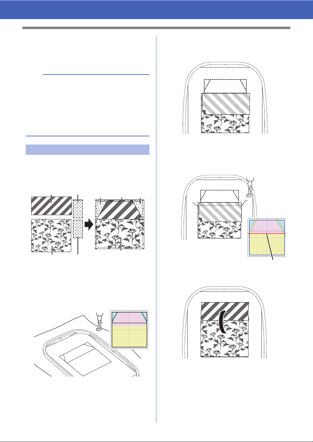
1 Cut the fabric for each piece.
3 With right sides together, place fabrics a and
b so that their top edges are aligned with the
horizontal line at the center of the base fabric.
4 For this example, sew the [RED] line (1)
drawn first in "Step 6 Drawing straight lines for
stitching fabrics with right sides together" on
page 17.
2 Hoop the base fabric in the embroidery frame,
and then sew the first color for positioning
fabric.
For this example, sew the [BLACK] line drawn
in "Step 5 Drawing straight lines for positioning
fabric" on page 16.
5 Fold open the fabrics that were sewn together.
19
Page 21
Tutorial 1: Making a Quilt Using an Embroidery Pattern
Line (2)Line (3)
Line (4)
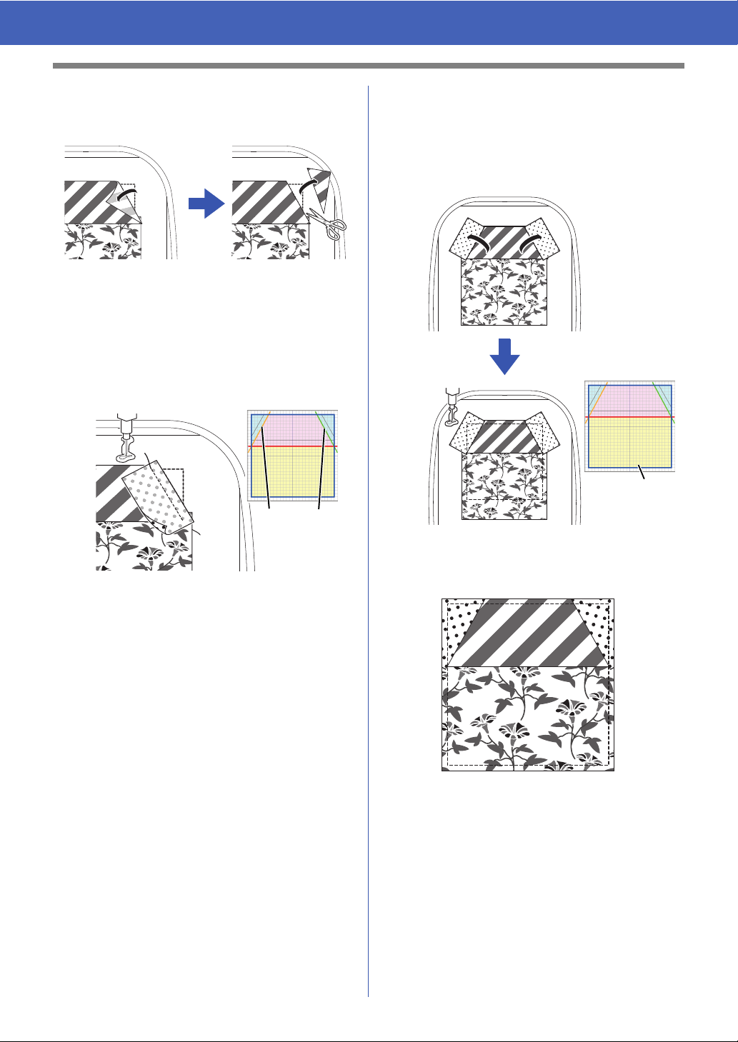
6 Fold the right side of fabric b along the
upper-right diagonal line in the base fabric,
and then use scissors to cut the fabric.
7 With its right side down, place fabric c on top
so that it is aligned with the upper-right
diagonal line in the base fabric. Then, start the
machine.
For this example, sew the [LIME GREEN]
line (2) drawn in "Step 6 Drawing straight lines
for stitching fabrics with right sides together"
on page 17.
9 Open the fabrics, and then sew around the
house pattern.
For this example, sew the [BLUE] line (4)
drawn in "Step 6 Drawing straight lines for
stitching fabrics with right sides together" on
page 17.
8 Repeat 6 and 7 for fabric d, and then start
the machine.
For this example, sew the [PUMPKIN] line (3)
drawn in "Step 6 Drawing straight lines for
stitching fabrics with right sides together" on
page 17.
10 Cut around the house pattern with a 7 mm
seam allowance.
20
Page 22
Tutorial 2: Arranging Stitch Patterns
Tutorial 2: Arranging Stitch Patterns
This section will describe how to arrange stitch patterns in order to create an embroidery design.
Built-in stitch patterns can be duplicated, flipped over and rotated to create an original embroidery design.
We recommend using a built-in stitch pattern in its original size, or resizing it only slightly.
The sample file for this tutorial is located at:
Documents (My documents)\PE-DESIGN PLUS2\Tutorial\Tutorial_2
b
Stitch patterns contain a collection of information including needle drop points and thread color order. Upon
being resized, the stitching becomes either more dense or light while maintaining the unchanged needle drop
point pattern. These changes may have an influence on the quality of your embroidery project.
Step 1 Setting the design page size
Step 2 Importing and rotating a pattern
Step 3 Duplicating a pattern
Step 4 Flipping a pattern
Step 5 Arranging patterns
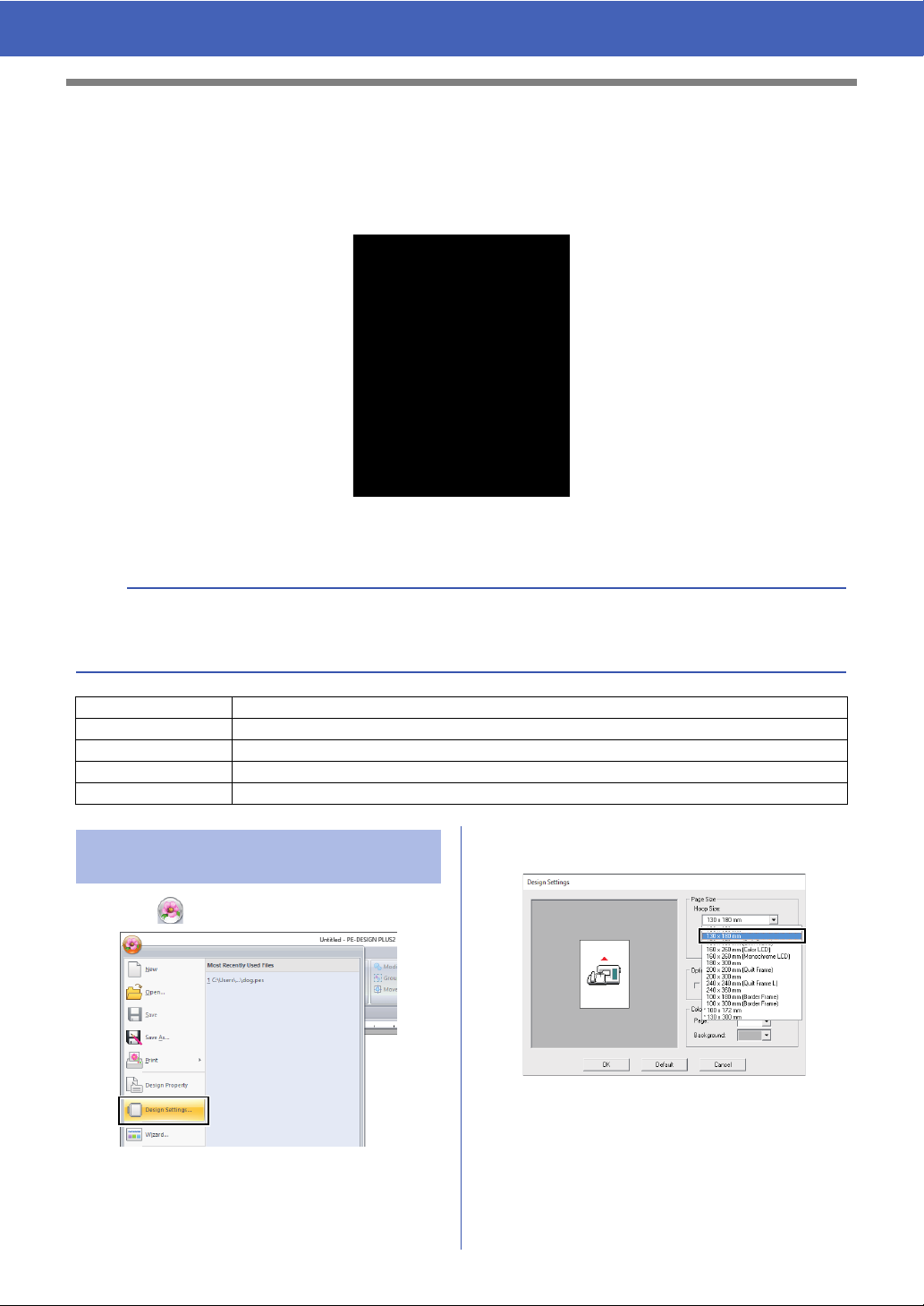
Step 1 Setting the design page
size
1 Click , then [Design Settings].
2 From the [Hoop Size] selector, select [130 ×
180 mm], and then click [OK].
21
Page 23
Tutorial 2: Arranging Stitch Patterns
a
a
a
b
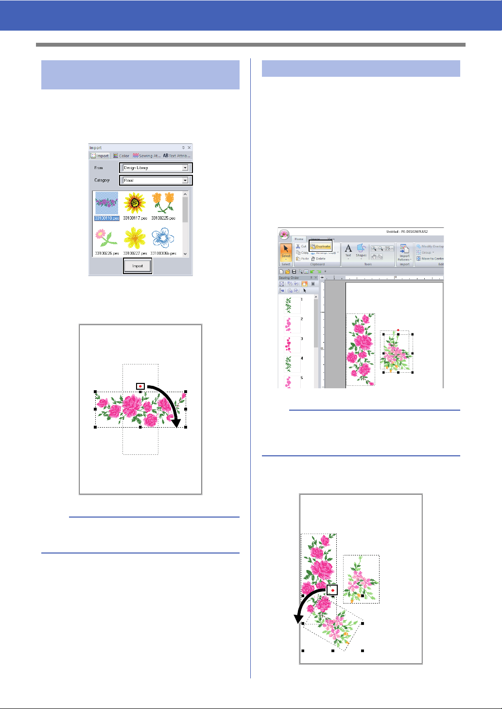
Step 2 Importing and rotating a
pattern
1 In the [Import] pane, select [Design Library]
from the [From] selector, then [Floral] from
the [Category] selector. Select
[33100110.pes], and then click [Import].
2 While holding down the <Shift> key, drag the
red dot at the top of the pattern to the right to
rotate the pattern 90° clockwise a.
Step 3 Duplicating a pattern
1 As in "Importing and rotating a pattern" on
page 22, import pattern [33103503a.pes]
from the [Floral] category in the [Import]
pane.
2 Select the pattern, and then click the [Home]
tab.
3 Click [Duplicate] in the [Clipboard] group to
duplicate the pattern.
The duplicate appears, overlapping the
original pattern and offset down and to the
right.
b
Holding down the <Shift> key while dragging the
red dot rotates the pattern in 15° increments.
3 Drag the pattern a to the left side.
b
The [Duplicate] command can also be selected
from the menu that appears after right-clicking the
selected pattern.
4 Move the duplicate pattern below pattern a,
and then rotate it 60° counterclockwise
22
b.
Page 24
Tutorial 2: Arranging Stitch Patterns
b
a
c
a
a
’
b
b
’
c
c
’
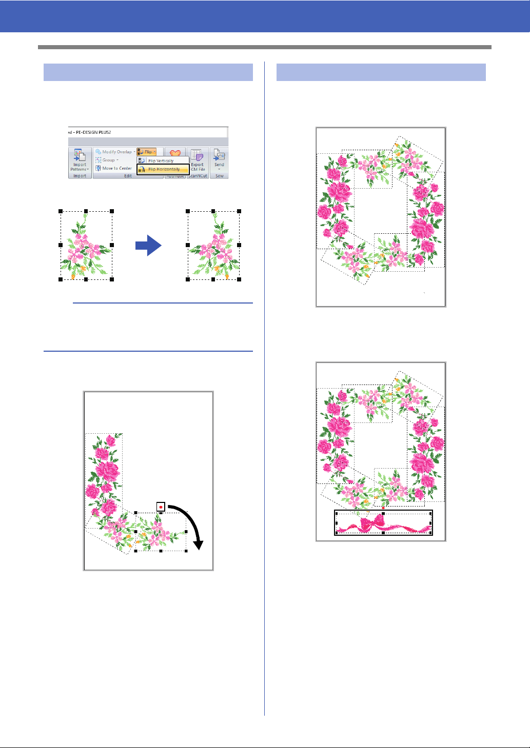
Step 4 Flipping a pattern
1 Select the original pattern, then click [Flip] in
the [Edit] group of the [Home] tab, and then
click [Flip Horizontally].
The selected pattern is flipped horizontally.
b
The [Flip] command can also be selected from the
menu that appears after right-clicking the selected
pattern.
2 Move the flipped pattern to the right of pattern
b, and then rotate it 90° clockwise c.
Step 5 Arranging patterns
1 Arrange the patterns to create a circle as
shown in the figure, using the [Duplicate] and
[Rotate].
2 Select [no77_2.pes] in the [Misc] category of
the [Import] pane, then click [Import], and
then move it below the flower patterns.
Change the sewing order as desired.
23
cc For details, refer to "Editing the sewing
order" on page 38.
Page 25
Tutorial 3: Changing the Stitching for Each Shape Pattern
Tutorial 3: Changing the Stitching for
Each Shape Pattern
The sew type for areas within closed outlines of text patterns or shapes can be specified.
The sample file for this tutorial is located at:
Documents (My documents)\PE-DESIGN PLUS2\Tutorial\Tutorial_3
Step 1 Importing an outline shape
Step 2 Applying motif stitches to line
Step 3 Applying programmable stitches to a shape
Step 4 Applying motif stitches to a shape
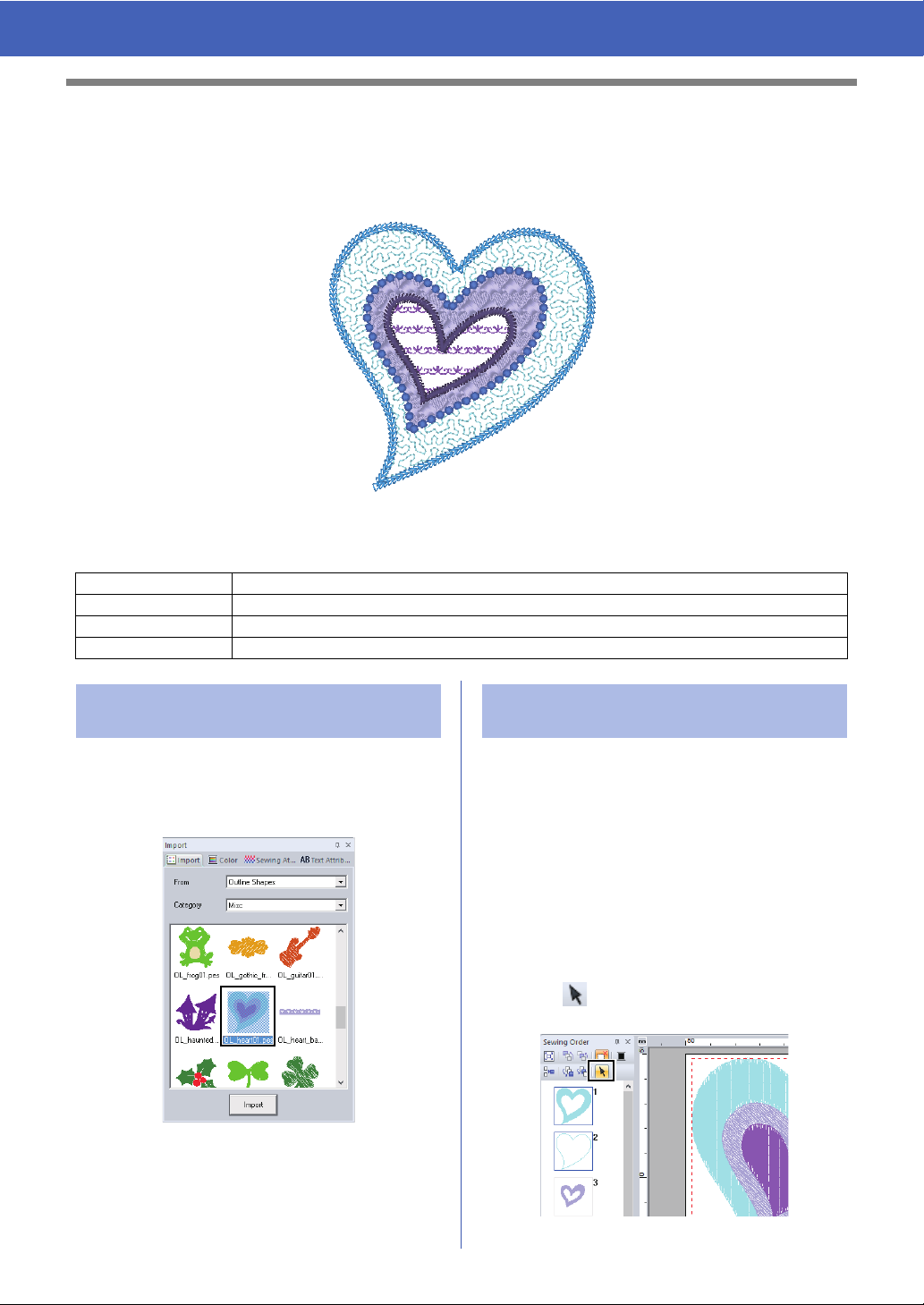
Step 1 Importing an outline
shape
1 In the [Import] pane, select [Outline Shapes]
from the [From] selector, then [Misc] from the
[Category] selector. Select
[OL_heart01.pes], and then click [Import].
Detailed line and region attribute settings can be
specified from the [Sewing Attributes] pane. Now,
we will specify settings for line sewing and region
sewing for the largest heart pattern.
1 Click on workspace to deselect the heart
2 Click at the top of the [Sewing Order]
Step 2 Applying motif stitches to
line
pattern.
While holding down the <Ctrl> key, click the
line (frame 2) and region (frame 1) of the
largest heart pattern arranged in the [Sewing
Order] pane.
pane.
24
Page 26
Tutorial 3: Changing the Stitching for Each Shape Pattern
1
2
Palette mode List mode
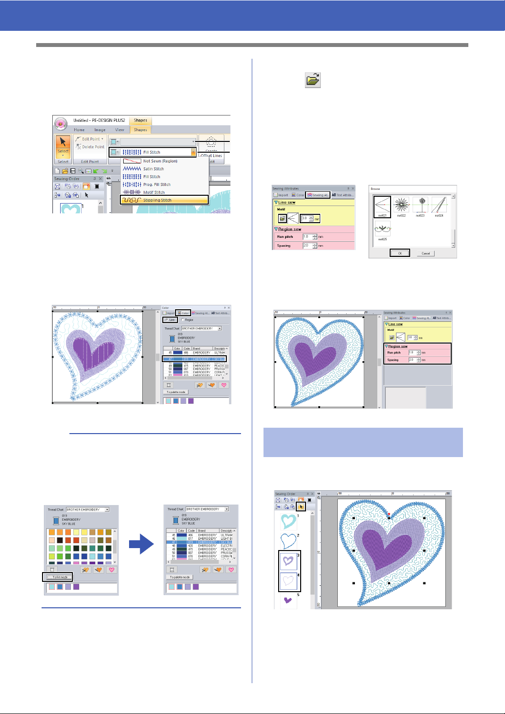
3 Click the [Shapes] ribbon tab.
4 Click the [Region sew type] selector in the
[Sew] group, and then select [Stippling
Stitch].
1 Line sew type selector
2 Region sew type selector
5 Click the [Line sew type] selector in the
[Sew] group, and then select [Motif Stitch].
6 Click the [Color] tab. Select the [Line] check
circle, and then click [SKY BLUE] in the list.
7 Click the [Sewing Attributes] tab and then
click .
If the [Sewing Attributes] pane is not
displayed, click the [View] tab, then
[Attributes], then [Sewing Attributes].
Select the desired motif stitch pattern from the
[Browse] dialog box, and then click [OK].
Specify the motif size.
For this example, select [mot021] and 3.0 mm
for the motif size.
8 Specify the region sew settings.
For this example, select 1.8 mm for the run
pitch and 2.0 mm for the spacing.
b
When the color palette is displayed in list mode,
the names of the thread colors are shown. To
switch to list mode, click [To list mode] in the
[Color] pane.
Step 3 Applying programmable
stitches to a shape
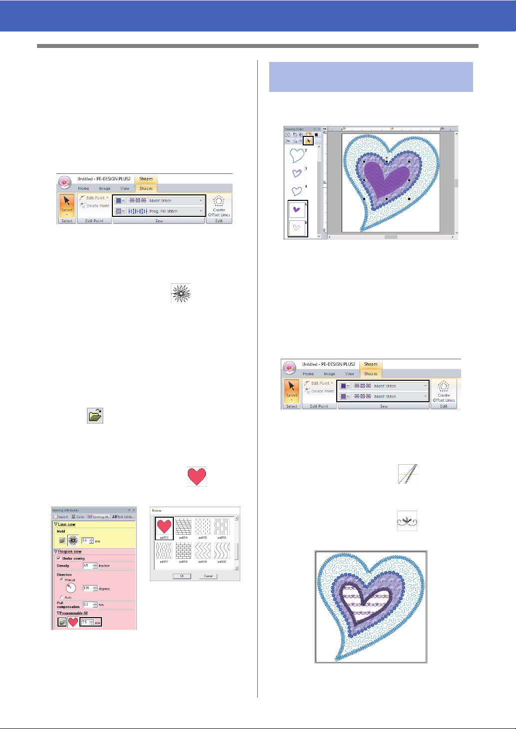
1 Select the second-largest heart pattern
(frames 3 and 4) in the [Sewing Order] pane.
25
Page 27
Tutorial 3: Changing the Stitching for Each Shape Pattern
2 Set a color and sew type for each shape as
follows.
Line sew
• Line sew type : Motif Stitch
• Line color : CORN FLOWER BLUE
Region sew
• Region sew type : Prog. Fill Stitch
3 Click the [Sewing Attributes] tab, and then
specify the following settings.
Line sew
• Motif pattern : mot022
• Motif size : 3.6 mm
Region sew
• Under sewing : ON
• Density : 4.5 line/mm
• Direction : Manual, 135 degrees
• Pull compensation : 0.3 mm
Step 4 Applying motif stitches to
a shape
1 Select the smallest heart pattern (frames 5
and 6) in the [Sewing Order] pane.
2 Click the [Shapes] tab.
Line sew
• Line sew type : Motif Stitch
• Line color : PURPLE
Region sew
• Region sew type : Motif Stitch
4 Click under the [Programmable fill],
select the desired pattern in the [Browse]
dialog box, and then click [OK].
For this example, select [pat013].
• Fill stitch pattern : pat013
• Pattern size : 7.5 mm
3 Click the [Sewing Attributes] tab, and then
specify the following settings.
Line sew
• Motif pattern : mot024
• Motif size : 3.0 mm
Region sew
• Motif pattern : mot025
• Motif size : 7.5 mm
26
Page 28
Tutorial 4: Editing an Imported Shape to Create an Embroidery Design for an
Appliqué
Tutorial 4: Editing an Imported Shape to Create an Embroidery Design for an Appliqué
This section will describe how to edit imported shapes and use the Applique Wizard.
The Applique Wizard provides instructions for easily creating appliqués. For this example, we will create an
appliqué that has holes (empty regions).
The sample file for this tutorial is located at:
Documents (My documents)\PE-DESIGN PLUS2\Tutorial\Tutorial_4
Step 1 Importing patterns
Step 2 Editing points and modifying shapes
Step 3 Using the mirror copy tool
Step 4 Specifying hole sewing
Step 5 Creating appliqués
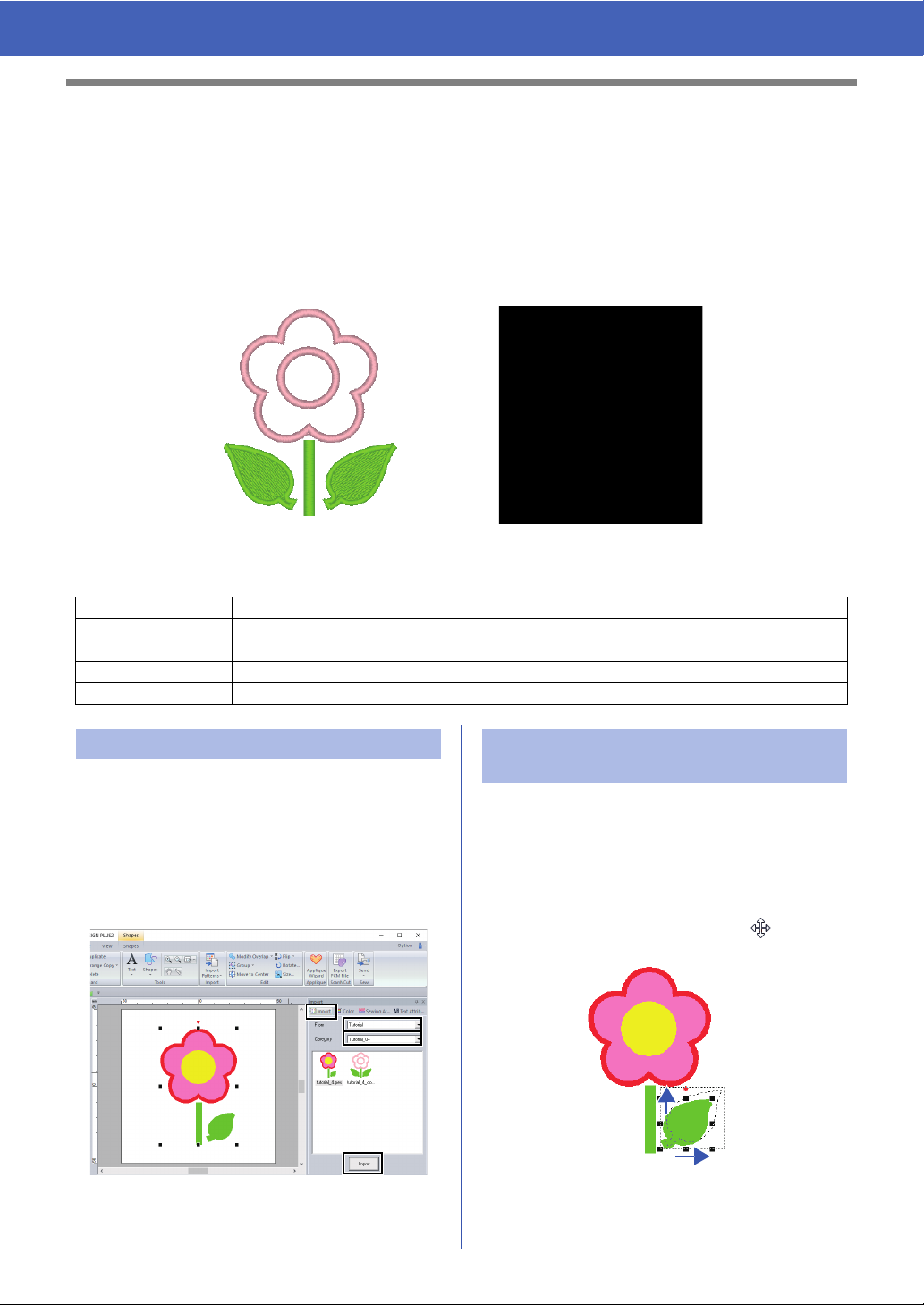
Step 1 Importing patterns Step 2 Editing points and
Shapes can be created either by drawing them with
the Shapes tools or by importing sample shape
patterns.
Now, we will edit a point in the leaf.
modifying shapes
1 Click on workspace to deselect the flower.
1 To import a shape, select [Tutorial] from the
[From] selector of the [Import] pane, then
[Tutorial_04] from the [Category] selector.
Select the shape, and then click [Import].
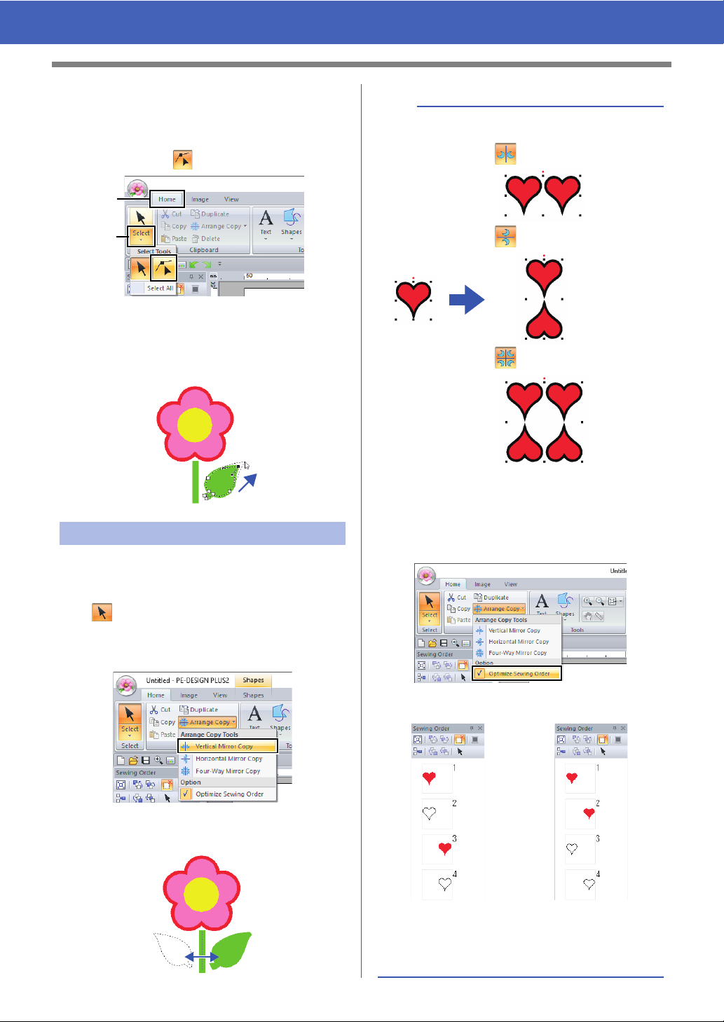
Click on the leaf to select it. Left click and drag
the handle to adjust the leaf.
Place the pointer over the leaf so that the
shape of the pointer changes to , and then
drag the leaf to the desired position.
27
Page 29
Tutorial 4: Editing an Imported Shape to Create an Embroidery Design for an
(A)
(B)
Vertical Mirror Copy
Horizontal Mirror Copy
Four-Way Mirror Copy
[Optimize Sewing Order]
not selected
[Optimize Sewing Order]
selected
The sewing order is the
order in which patterns are
created.
Patterns will be sewn so
that those with the same
thread colors will be
connected.
Appliqué
2 Edit a point.
(A) Click the [Home] tab.
(B) Click [Select] in the [Select] group, and
then click .
(C) Click the shape for the leaf.
The points in the shape appear.
(D) Select the point, and then drag the point to
the desired location.
b
• Arrange copy type
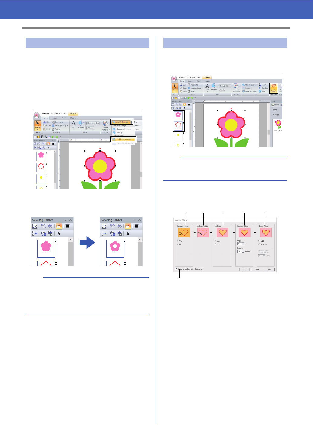
Step 3 Using the mirror copy tool
1 Click the [Home] tab.
2 Click [Select] in the [Select] group, then click
, and then select the leaf.
3 Click [Arrange Copy] in the [Clipboard]
group, and then click [Vertical Mirror Copy],
4 Move the pointer, and then click when the
patterns are arranged as desired.
• Optimize sewing order
Before using an [Arrange Copy] tool, optimizing
the sewing order adjusts the sewing order of the
patterns created with the [Arrange Copy] tool in
order to reduce the number of thread color
changes.
28
Page 30
Tutorial 4: Editing an Imported Shape to Create an Embroidery Design for an
ab c d e
f
Appliqué
Step 4 Specifying hole sewing
Now, we will apply a setting so that the overlapping
areas are not sewn twice.
1 While holding down the <Ctrl> key, click the
circle, then the flower.
2 Click the [Home] tab, then click [Modify
Overlap] in the [Edit] group, and then click
[Set hole sewing].
When hole sewing is specified, the pattern
displayed in the [Sewing Order] pane
changes.
Step 5 Creating appliqués
1 Select the outer pattern, and then click
[Applique Wizard] in the [Home] tab to start
the [Applique Wizard] dialog box.
b
Be sure to select the outer pattern before starting
the [Applique Wizard].
2 Specify settings in the [Applique Wizard]
dialog box in the following order
a - f.
a
Hole sewing cannot be applied if one of the
patterns is not completely enclosed within the
other pattern.
cc "Hole sewing" on page 56.
a Applique Material
Specify cutting lines for the appliqué.
The outline of the appliqué can be sewn
as running stitches to be sewn onto the
appliqué fabric as a guide for cutting it out.
For this example, select [Yes].
b Applique Position
The guideline for attaching the appliqué
piece is set to be sewn automatically.
c Tack down
Specify basting of the appliqué.
The appliqué piece can be basted onto
the base fabric.
For this example, select [Yes].
29
Page 31

Tutorial 4: Editing an Imported Shape to Create an Embroidery Design for an
Appliqué
d Covering Stitch
Specify the stitching for securing the
appliqué. Select the sew type and other
attributes ([Width] and [Density]) for
finishing the appliqué.
For this example, set [Width] to "3.0
mm" and [Density] to "5.0 line/mm".
e Output Pattern
Select whether covering stitches will be
added around the entire pattern ([Add])
or covering stitches will be sewn for shape
lines ([Replace]).
For this example, select [Replace].
Add Replace
b
To return all parameters to their default settings,
click [Default].
3 Click [OK] to exit the Applique Wizard dialog
box.
cc "About the Output Pattern settings"
on page 30.
f Create an applique with hole sewing
Select this check box when creating an
appliqué with holes (empty regions).
For this example, select this check
box.
b
•The [Create an applique with hole
sewing] check box appears when only
the outer pattern with hole sewing
applied or only a text pattern (with fonts
other than built-in fonts 025 and 029, or a
Small Text font) is selected, or when
[Replace] is selected under [Output
Pattern].
* Multiple text patterns can be selected if
certain conditions are met.
• The shape of the appliqué material
appears as shown below, depending on
whether the [Create an applique with
hole sewing] check box is selected or
not.
When the [Create an
applique with hole
sewing] check box is
cleared
■ About the Output Pattern settings
Add
• Covering stitches will be created around the
original pattern.
• Under [Distance from original Pattern], specify
the distance of the covering stitches from the
original pattern.
• This can be used to combine various patterns.
a
The [Add] setting is not available if the stitch
pattern does not exist, for example, when both the
line and region sew types are set to [Not Sewn].
When the [Create an
applique with hole
sewing] check box is
selected
30
Page 32

Tutorial 4: Editing an Imported Shape to Create an Embroidery Design for an
[Add]
[Replace]
[Add]
[Replace]
Appliqué
Replace
• Covering stitches will be sewn for outlines in the
original pattern.
• The original pattern will be deleted.
• Shape and text patterns can be used as the
original pattern. However, the following patterns
cannot be used.
- Open lines
- Closed lines that are intersecting
- Text created with built-in fonts 025 and 029, or
a Small Text font
- Original patterns containing both a shape
pattern and a text pattern
b
When multiple patterns are selected, covering
stitches will be created as shown below.
• If the patterns do not overlap
Covering stitches will be created for each
pattern.
• If the patterns overlap
With the [Add] setting, covering stitches will be
created for an outline around all patterns.
31
Page 33

Specifying the Design Page Settings
ba c
gdfe
Specifying the Design Page Settings
The color and size of the Design Page can be changed. You can select a Design Page size according to the
size of hoop that you will be using with your embroidery machine. You can also specify a custom size for the
Design Page for embroidery patterns that will be split and embroidered in multiple sections.
1 Click , then [Design Settings].
2 Specify the settings for the Design Page, and
then click [OK].
d Optimize hoop change
This setting can be selected if a multiposition hoop (100 × 172 mm or 130 × 300
mm) has been selected as the Design
Page size.
Select the check box to optimize the
sewing order/order of hoop position
changes so that the number of times that
the hoop position is changed is reduced to
the minimum.
This reduces the risk of misalignment in
the embroidery pattern or uneven
stitching from changing the hoop position
too often.
e Page
Select the desired color for the Design
Page.
f Background
Select the desired color for the work area.
g Default
To return to the default settings, click this
button.
a
• The Design Page sizes 100 × 172 mm, 130 ×
300 mm indicated by the "*", are used to
embroider multi-position designs using a special
embroidery hoop attached to the embroidery
machine at three installation positions.
a Hoop Size
Select the desired hoop size from the
selector.
b Rotate 90 Degrees
Select this check box to arrange the
pattern in a Design Page rotated 90°.
c Edit User Hoop
Click this button to display the [User
Hoop Settings] dialog box, where a user
hoop size can be added. The added user
hoop size appears at the bottom of the list.
cc "Specifying a user hoop size" on
page 33
cc "Tutorial 8: Creating Design for Multi-Position
Hoops" on page 93
• Do not select a hoop size larger than the
embroidery hoop that can be used with your
machine.
32
Page 34

Specifying the Design Page Settings
d
a
b
e
f
c
1
Specifying a user hoop
size
a Width, Height
Type in the size of the hoop to be added.
b Comment
If text was entered in this box, that text
appears beside the size.
c Add Hoop
Click this button to add the hoop size.
d User Hoop List
The added hoop size appears in the list.
Select a hoop size in this list to change the
display order or to delete it.
e Up, Down
Click these buttons to move the selected
hoop size up or down in the display order.
f Delete Hoop
Click this button to delete the selected
hoop size.
a
• A User Hoop cannot rotate 90°.
• A User Hoop cannot be added to the Section
Size (for Hoop Size) selector under Custom
Size.
• Do not create a Custom Hoop larger than the
embroidery hoop that can be used with your
machine.
Changing the guideline
settings
1 Click the [View] tab.
2 Select the [Guideline] check box in the
[Guideline] group.
3 Click a ruler in the Design Page.
appears, and a guideline is drawn.
1 Guideline
• To move a guideline, drag .
• To delete a guideline, click .
b
• A guideline is added each time the ruler is
clicked. In addition, up to 100 guidelines each
can be added to the horizontal and vertical
rulers.
• While a guideline is being dragged, its position is
shown in the status bar.
• When the [Guideline] check box is cleared, the
guidelines are hidden.
• If both the [Show Grid] and [Snap to Grid]
check boxes are selected in the [Grid] group,
the guidelines will be added/moved along the
lines of the grid.
cc "Changing the grid settings" on page 15
33
Page 35

Checking Embroidery Patterns
1
2
3
1
4
2
3
Checking Embroidery Patterns
Zooming
1 Click the [Home] tab.
2 Click or in the [Tools] group.
: Click the Design Page to zoom in.
(Right-click the Design Page to zoom
out.)
: Click the Design Page to zoom out.
(Right-click the Design Page to zoom
in.)
Otherwise, click beside , and then
click [Zoom all], [Selected object zoom] or
[Actual size zoom].
Using the Pan tool
The part of the work area that is displayed can easily
be changed by using the Pan tool.
1 Click the [Home] tab.
2 Click in the [Tools] group.
3 Drag the work area to view the desired part.
b
• You can also pan the work area when any other
tool is selected by holding down the <Space>
key while dragging the pointer.
• To scroll horizontally, hold down the <Alt> key
while rotating the mouse wheel.
Using the Measure tool
1 Zoom all
The entire Design Page is displayed to fit within
the window. The same operation can be
performed by clicking in the [Tools]
group.
2 Selected object zoom
The Design Page is zoomed to display only the
selected objects.
3 Actual size zoom
The Design Page is displayed at its actual size.
b
• Zooming is also possible by dragging the
[Zoom] slider in the status bar or clicking the
Zoom ratio.
• You can also zoom in or out when any other tool
is selected by holding down the <Ctrl> key while
rotating the mouse wheel.
cc "PE-DESIGN PLUS2 Window" on page 10
1 Click the [Home] tab.
2 Click in the [Tools] group.
3 Click the two points, one on each end of the
distance that you want to measure.
The length appears in the status bar at the
bottom of the window.
1 Length
2 Width
3 Height
4 Angle
34
Page 36

Checking Embroidery Patterns
b
Click / to switch the measurement units
between millimeters and inches.
■ Realistic View
You can display a realistic view of it in order to see
how the design will appear once it is sewn.
Changing the display of
the embroidery design
1 Click the [View] tab.
2 Click [Solid], [Stitch] or [Realistic] in the
[View Mode] group.
■ Solid View
b
Changing realistic view settings
1. Click the [View] tab.
2. Click [Realistic View Settings] in the [View
Mode] group.
3. If necessary, specify settings for [Thread
Width], [Contrast] and [Brightness], and
then click [Apply] ([OK]).
■ Stitch View
You can display a stitch view of it in order to see how
the stitching is connected.
35
Page 37
Checking Embroidery Patterns
c
g h
a b d e
f
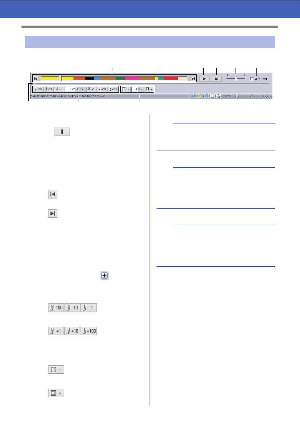
Checking the stitching with the Stitch Simulator
1 Click the buttons to view a simulation of the stitching.
a Starts the stitching simulation. During
stitching simulation, this button changes
to , which can be clicked to
temporarily stop the simulation.
b Stops the simulation and returns to the
previous display.
c The slider shows the current location in
the simulation. In addition, the slider can
be moved to change the position in the
simulation.
: Returns to the beginning of stitching
and stops the simulation.
a
If the Stitch Simulator is not displayed at the
bottom of the window, click [Stitch Simulator] on
the [View] tab.
b
• The zoom tools and pan tool can be used while
a simulation is being viewed. If any other
command is selected, the simulation stops.
• If a value is entered at
is reversed/advanced to the indicated location.
g or h, the simulation
: Advances to the end of stitching and
stops the simulation.
d Drag the slider to adjust the simulation
stitching speed.
e Select this check box to automatically
scroll the simulation of the pattern when it
is too large to be fully displayed.
f Click to hide the bottom section of the
Stitch Simulator. Click to display it
again.
g Shows the number of the current stitch/
total number of stitches.
: Reverses the
simulation by the indicated number of
stitches.
: Advances the
simulation by the indicated number of
stitches.
h Shows the number of the color being
drawn/total number of colors used.
: Returns to the beginning of
stitching for the current or previous thread
color.
: Advances to the beginning of
stitching for the next color.
a
• If a pattern was selected when the stitching
simulation was started, only the selected pattern
is drawn in the simulation.
•The [Auto Scroll] check box is not available in
Realistic View.
36
Page 38

Checking Embroidery Patterns
ONOFF
12
Checking and Editing the
Sewing Order
1 Click the [View] tab.
2 Click [Sewing Order] in the [Show/Hide]
group.
Clicking the button switches between
displaying and hiding the Sewing Order.
3 Click and in the [Sewing Order]
pane.
Zoom
Click to enlarge each pattern to fill its
frame.
b
When multiple same color
patterns are combined into one
frame, appears to the left of
that frame.
Click to display the combined
same color patterns in separate
frames.
appears under the first frame,
and each frame is displayed with a
subnumber following the first, to
indicate its sewing order within the
patterns of the same color.
Click to recombine all of the
same color patterns back into one
frame.
■ Selecting a pattern
1 Click a frame containing the pattern in the
[Sewing Order] pane.
Show by color order
Click to display in one frame all
patterns of the same color that will be
sewn together.
1 Blue line
2 Marching line
b
To select multiple patterns, hold down the <Shift>
or <Ctrl> key while clicking the frames for the
desired patterns. In addition, multiple frames can
be selected by dragging the pointer over them.
2 Click in the [Sewing Order] pane to
select the pattern in the Design Page
corresponding to the frame selected in the
[Sewing Order] pane. The pattern can also
be selected by double-clicking its frame in the
[Sewing Order] pane.
37
Page 39

Checking Embroidery Patterns
■ Editing the sewing order
The sewing order can be
changed by selecting the frame
containing the pattern, then
dragging the frame to the new
location. A red line appears,
indicating the position where the
frame is being moved.
The frame can also be moved by
clicking , , , or
in the [Sewing Order] pane.
Sew First
Click to move the selected pattern to
the beginning of the sewing order.
Sew Previous
Click to move the selected pattern
ahead one position in the sewing
order.
Sew Next
Click to move the selected pattern
back one position in the sewing order.
Sew Last
Click to move the selected pattern to
the end of the sewing order.
■ Changing colors
1 Select one or more frames in the [Sewing
Order] pane, and then click at the top of
the [Sewing Order] pane.
The Color pane appears in front of the other
panes.
2 Click the desired color in the [Color] pane.
cc "Color pane" on page 61
■ Changing sewing attributes
1 In the [Sewing Order] pane, select one or
more frames containing a pattern other than a
stitch pattern.
The sew type selector for the selected
frame appears.
2 Click the [Sewing Attributes] tab.
If the [Sewing Attributes] pane is not
displayed, click the [View] tab, then
[Attributes], and then click [Sewing
Attributes].
3 Change the sewing attributes and sew type.
cc “Line sew types”, "Region sew types" on
page 63 and "Specifying sewing
attributes" on page 63
■ Displaying/hiding frames not
sewn
For details, refer to "Displaying frames not sewn" on
page 41.
38
Page 40

Checking Embroidery Patterns
Checking embroidery
design information
Click , then [Design Property].
You can enter comments and information about the
pattern to a saved .pes file.
b
The information shown in the color list can be
switched.
• Color Changes
The thread color information for each color
change is displayed. This allows you to check
the total number of thread color changes.
• Total Colors
The thread color information for the necessary
threads is displayed. This allows you to check
the total number of thread colors.
b
• You can select and check the properties of
individual patterns within the embroidery design
by selecting the pattern before opening this
dialog box. In this case, clearing the [Show
about selected Object(s)] check box switches
the dialog box to display properties for all
patterns in the Design Page.
•If [Hoop Size] was set to a multi-position hoop
(100 × 172 mm or 130 × 300 mm), a [Design
Property] dialog box appears with the sewing
information for each hoop of the pattern in the
Design Page.
39
Page 41

Tutorial 5: Creating Embroidery Patterns From a Vector File
Tutorial 5: Creating Embroidery Patterns
From a Vector File
An embroidery pattern can be created from an image, such as photo or illustration. WMF, EMF and SVG image
files can be converted to embroidery patterns.
The sample file for this tutorial is located at:
Documents (My documents)\PE-DESIGN PLUS2\Tutorial\Tutorial_5
Step 1 Importing vector images (SVG files)
Step 2 Displaying frames not sewn
Step 3 Decorating the outer heart shape
Step 1 Importing vector images
(SVG files)
Vector image data in the ".wmf" (Windows Metafile),
".emf" (Enhanced Metafile) and ".svg" (Scalable
Vector Graphics) file formats can be converted to
shape patterns.
1 Click the [Home] tab.
2 Click [Import Patterns] in the [Import] group,
and then select [from Vector Image].
3 Select the file to be imported, and then click
[Open].
For this example, we will import
[svg_heart.svg].
The image appears in the [Design Page]
as a shape pattern.
40
Page 42

Tutorial 5: Creating Embroidery Patterns From a Vector File
ON OFF
b
• Frames containing patterns that will not be sewn
can be displayed or hidden.
• As a default, frames containing patterns that will
not be sewn will be hidden.
• When frames containing patterns that will not be
sewn are displayed, that frame can be selected
and its pattern can be edited.
Step 3 Decorating the outer heart
shape
a
• Image, text, width of the line, gradient, opacity,
and any other styles or attributes of graphics will
not be imported. With files in the ".emf" and
".svg" formats, the data is converted while
retaining curves.
• The data on all layers of an SVG file, regardless
of whether it is displayed or hidden, will be
converted into the embroidery pattern.
Step 2 Displaying frames not
sewn
1 Click in the toolbar at the top of the
[Sewing Order] pane.
Hide Objects Not Stitched
Click to display hidden objects that are
not to be stitched.
1 Select the colored area of the heart shape,
and then click [Shapes] tab.
2 Specify a color and sew type for each shape
as follows.
Line sew
• Line sew type : Motif Stitch
• Line color : SALMON PINK
Region sew
• Region sew type : Prog. Fill Stitch
• Region color : DEEP ROSE
41
Page 43

Tutorial 5: Creating Embroidery Patterns From a Vector File
3 Click the [Sewing Attributes] tab, and then
specify the following settings.
Line sew
• Motif pattern : mot023
• Motif size : 4.5 mm
Region sew
• Under sewing : ON
• Density : 4.8 line/mm
• Direction : Manual, 45 degrees
• Pull compensation : 0.0 mm
• Programmable fill
- Fill stitch pattern : pat012
- Pattern size : 6.0 mm
4 In the [Sewing Order] pane, drag frame 2
(heart shape outline) to the top (above the
outer heart shape).
Change the sewing attributes for objects that
are not to be stitched as desired.
■ Creating an embroidery pattern
using vector images drawn with
other image-editing applications
Being converted to the ".svg" file format, vector
image files created with other commercially
available applications (e.g., ".ai" (Adobe Illustrator
Artwork) and ".cdr" (CorelDraw file)) can be
imported.
First convert the vector image files into either of
WMF, EMF or SVG file format with your
applications, and then import them to PE-DESIGN
PLUS2 by following the steps described in
"Importing vector images (WMF/EMF/SVG)".
b
Raster image files (e.g., ".bmp" and ".jpg") can be
used as background images in PE-DESIGN
PLUS2, or they can be converted to embroidery
patterns using the Image To Stitch Wizard.
cc For details, refer to "Creating Embroidery
Patterns Using Images" on page 73.
42
Page 44

Opening/Importing Embroidery Designs
Opening/Importing Embroidery Designs
Creating a new embroidery
design
Click , then [New].
b
The size of the Design Page can be changed.
cc "Specifying the Design Page Settings" on
page 32
Opening a PE-DESIGN
PLUS2 file
b
• To view the data in the selected folder as
thumbnails in the [Browse] dialog box, click
[Browse].
• To see a more detailed design, select a file, and
then click [Preview].
1 Click , then [Open].
2 Select the drive, the folder and the file, and
then click [Open], or double-click the file's
icon.
• To open the displayed file, click [Open].
• If no files are listed, there are no .pes files in the
selected folder. Select a folder containing a .pes
file.
• If the selected file is in a format other than the
.pes format, the message "Unexpected file
format" appears in the [Preview] window.
b
A file can be opened in any of the following ways.
• Drag the embroidery design from file Windows
Explorer into the PE-DESIGN PLUS2 window.
• Double-click the embroidery design file in
Windows Explorer.
43
Page 45

Opening/Importing Embroidery Designs
1
a
If a .pes file created with PE-DESIGN 10 or earlier
is opened with this software, the message “This
file will be imported into a new Design Page.”
appears before the embroidery design is displayed
on the new Design Page.
Importing embroidery
designs
Embroidery designs can be imported from the
[Import] pane. For more details on the [Import]
pane, refer to "Example of Importing Embroidery
Data" on page 13.
■ From Design Library
1 Click the [Home] tab.
2 Click [Import Patterns] in the [Import] group,
and then click [from Design Library].
■ From a folder
1 Click the [Home] tab.
2 Click [Import Patterns] in the [Import] group,
and then click [from File].
3 Click .
3 From the [Category] selector, select a
category to display the corresponding
embroidery data.
4 Select the file icon for the design to be
imported, and then click [Import].
1 Indicates the path to the currently selected
folder.
4 Select a folder, and then click [OK].
44
Page 46

Opening/Importing Embroidery Designs
5 Click [File Type] in the [Import] pane. Select
the file name extensions of the corresponding
embroidery data to be displayed, and then
click [OK].
6 Select the file icon, and then click [Import].
a
When importing designs from other vendors, be
sure to choose a design that will fit in the Design
Page.
b
Since .dst files do not contain thread color
information, the colors of an imported .dst file may
not appear as expected. You can change the
thread colors by using functions in the [Sewing
Order] pane.
cc "Changing colors" on page 38
• When importing .dst files, the number of jump
stitches for thread trimming can be specified.
cc "Specifying the number of jumps in
embroidery design of the DST format"
on page 102
45
Page 47

Saving and Exiting
Saving and Exiting
Saving
■ Overwriting
Click , then [Save].
b
If no file name has been specified or if the file
cannot be found, the [Save As] dialog box
appears.
■ Saving with a new name
3 Click [Save] to save the data.
The new file name appears in the title bar of
the PE-DESIGN PLUS2 window.
Exiting
Click , then [Exit].
1 Click , then [Save As].
2 Select the drive and the folder, and then type
in the file name.
46
Page 48

a
c
e
b
d
Printing
Specifying print settings
Before printing, you may need to change the print
settings for the embroidery design files.
1 Click , then [Print], then [Print Setup].
a Specify the paper size.
b Specify the paper orientation.
c Print type
Actual Size:
Select this option to print the design at
actual size and the sewing information
(dimensions of the embroidery pattern,
sewing color order, stitch count and
hoop position) on separate pages.
Reduced Size:
Select this option to print a reduced
image together with all of the abovementioned information on a single
page.
d Print option
Print sewing area box & center axes:
Select this option to print black lines to
indicate the sewing area and the
center axes for the data. (This setting is
only available when [Actual Size] is
selected.)
Printing
Print template grid:
Select this check box to print green
lines to represent the grid printed on
the embroidery sheet included with the
hoop. (This setting cannot be selected
if [User Hoop] has been selected as
the Design Page size.)
Divide embroidery image into 2 pages:
Select this check box to print at actual
size and on A4- or Letter-size paper a
design that is larger than the paper size
by dividing it in two and printing each
half on different pages.
(This setting is only available when
[Actual Size] is selected in the [Print
Setup] dialog box and when the
Design Page is set to the larger hoop
sizes. This setting is not available if a
[User Hoop] size is selected.)
With this split printing feature, /
or / is printed in the lower-right
corner of the paper to indicate which
half is printed.
Color Changes:
Select this check box to print the thread
color change information for the
pattern.
When this check box is cleared, the
information for the necessary threads
is printed. This allows you to check the
total number of thread colors.
e Stitch image
Normal:
Select this option to print the design as
lines and dots.
Realistic:
Select this option to print a realistic
image of the design. To change the
settings of the realistic image, click
[Attributes].
cc"Changing realistic view settings" on
page 35
a
If the [Divide embroidery image into 2 pages]
check box is cleared and you print on paper of a
larger size, the design does not print in two halves.
Likewise, if you print on paper of a smaller size, the
design might be cut off.
47
Page 49

Printing
2 Click [OK].
cc "Changing the display of the embroidery
design" on page 35.
Checking a print image
You can preview the contents of the Design Page
before printing.
Click , then [Print], then [Print Preview].
Printing a Design Page
with sewing information
You can print the Design Page together with its
sewing information.
1 Click , then [Print], then [Print].
2 Select the necessary settings.
b
The print image can also be displayed by clicking
[Print Preview] in the [Print Setup] dialog box.
3 Click [OK] to begin printing.
4 Follow the instructions for the printer to finish
printing.
48
Page 50

Drawing Shapes and Reshaping
Rectangle
Circle
Oval
Example 1
Edge radius: 0.0 mm
Example 2
Edge radius: 20.0 mm
End point
Start point
Open line
Closed line
End point
Start point
Open curve
Closed curve
Drawing Shapes and Reshaping
Drawing Shapes
■ Drawing rectangle or circle shape
1 Click the [Home] tab.
2 Click [Shapes] in the [Tools] group, and then
click a tool icon under [Rectangle]/[Circle] to
select the desired [Rectangle]/[Circle] tool.
■ //
b
Rectangles with rounded corners
• To change the radius of the corners, click the
[Edge radius] selector in the [Outline] tab.
Then, type the desired radius, or select the
desired value.
• Specify the radius of the corners before drawing
the rectangle. The setting cannot be changed
after the rectangle has been drawn.
b
To draw a circle or square, hold down the <Shift>
key while dragging the pointer.
Drag the pointer in the Design Page.
: Rectangle
: Rectangle with rounded corners
: Circle or Oval
■ Drawing outlines (straight lines
and curves)
49
Page 51

Drawing Shapes and Reshaping
1 Click the [Home] tab.
2 Click [Shapes] in the [Tools] group, and then
click a tool icon under [Outline] to select the
desired Outline tool.
: Click points to draw a closed line
constructed of straight lines.
(Shortcut key: <Z>)
: Click points to draw a closed curve.
(Shortcut key: <X>)
: Click points to draw an open line
constructed of straight lines.
(Shortcut key: <Z>)
: Click points to draw an open curve.
(Shortcut key: <X>)
3 Click in the Design Page or drag the pointer to
draw the line.
3 Continue clicking to specify every point, and
then double-click the last point, or press the
<Enter> key.
b
• You can freely switch between the different line
types either by clicking a different button or by
pressing the shortcut key.
• When drawing a straight line, hold down the
<Shift> key while moving the pointer to draw
vertically or horizontally.
• Even after the pattern is drawn, you can change
the attributes of line ends.
cc "Changing the attributes of line ends" on
page 50.
• Even after the pattern is drawn, you can
transform straight lines into curves and vice
versa.
cc "Transforming straight lines into curves or
curves into straight lines" on page 52.
b
The shortcut keys are available only after an
Outline tool has been selected.
■ Straight lines/curves
1 Click in the Design Page to specify the start
point.
2 Click in the Design Page to specify the next
point.
The dotted lines change to solid lines.
b
• To remove the last point that was entered,
right-click the mouse button, or press the
<BackSpace> key.
• The Curve tool is used in the same way.
■ Changing the attributes of line
ends
After selecting a shape pattern, right-click it, and
then click [Open] or [Close] to change the line
ending.
50
Page 52

Drawing Shapes and Reshaping
Drag
Selected point
Click
Reshaping Embroidery
Patterns
Patterns can be reshaped by moving, adding or
deleting points. While creating shape patterns, a
clicked location becomes a point.
■ Selecting points
1 Click the [Home] tab.
2 Click [Select] in the [Select] group, and then
click to select the [Select Point] tool.
3 Click the shape pattern.
4 To select a single point, click an empty square.
■ Moving points
1 Select the point.
2 Drag the point to the new location.
b
• To move the point of a broken line, a curve, or
stitch data horizontally or vertically, hold down
the <Shift> key while dragging it.
• A selected point can also be moved with the
arrow keys.
• Points in patterns set for hole sewing can also
be moved. However, the point cannot be moved
to cross an outline. In order to move the point in
this way, cancel hole sewing first.
• If you start dragging by clicking elsewhere on the
outline of the pattern, a new point will be inserted
or the selected point(s) will be deselected.
b
Multiple points can be selected in any of the
following ways.
• Drag the pointer.
All points within the box are selected.
• Hold down the <Ctrl> key while clicking the
points.
To deselect a point, click the selected
point.
• Hold down the <Shift> key while pressing an
arrow key to select multiple points.
• Hold down the <Ctrl> key while pressing an
arrow key to change the point that is selected.
■ Inserting points
1 Select the [Select Point] tool.
2 Click the shape pattern.
3 Click the outline to add a point.
51
Page 53

Drawing Shapes and Reshaping
Selected point
Delete
To Curve
To Straight
■ Deleting points
1 Select the point.
2 Click the [Shapes] tab.
3 Click [Delete Point] in the [Edit Point] group.
Otherwise, press the <Delete> key to remove
the point.
■ Transforming straight lines into
curves or curves into straight
lines
■ Changing the curve type
1 Select a point on a curve.
2 Click the [Shapes] tab.
3 Click [Edit Point] in the [Edit Point] group,
and then click [To Smooth], [To Symmetry]
or [To Cusp].
To Smooth
To Symmetry
1 Select the point.
2 Click the [Shapes] tab.
3 Click [Edit Point] in the [Edit Point] group,
and then click [To Straight] or [To Curve].
To Cus p
4 Drag the solid black handle to adjust the
shape of the line.
b
The shape can be changed by dragging the solid
black handle on either side of the point.
52
Page 54

Editing Embroidery Designs
1
2
Editing Embroidery Designs
Selecting patterns
1 Click the [Home] tab.
2 Click [Select] in the [Select] group, and then
click .
3 Click the pattern.
1
Rotation handle
2 Handles
b
The status bar shows the dimensions (width and
height) of the pattern.
4 To select an additional pattern, hold down the
<Ctrl> key and click the other pattern.
■ Selecting all embroidery patterns
1 Click the [Home] tab.
2 Click [Select] in the [Select] group, and then
click [Select All] to select all patterns.
b
All patterns can also be selected by pressing the
shortcut keys <Ctrl> + <A>.
Moving patterns
■ Moving manually
Drag the selected pattern(s) to the desired location.
b
• To move the pattern horizontally or vertically,
hold down the <Shift> key while dragging it.
• Pressing the arrow keys moves the selected
pattern.
• Holding down the <Ctrl> key and dragging the
pattern creates a duplicate of the pattern at the
destination.
b
• You can also select patterns by dragging the
pointer across the pattern.
•Press the <Tab> key to select the next pattern in
the order that they were created.
• If multiple patterns are selected, a pattern can
be deselected by holding down the <Ctrl> key
while clicking the pattern.
■ Moving embroidery patterns to
the center
1 Select the pattern(s), and then click the
[Home] tab.
2 Click [Move to Center] in the [Edit] group.
53
Page 55

Editing Embroidery Designs
1
a
b
c
a
b
1
Scaling patterns
■ Scaling manually
1 Select the pattern(s).
1 Handles
2 Drag the handle to adjust the selected
pattern(s) to the desired size.
b
• If the <Shift> key is held down while a handle is
dragged, the pattern is enlarged or reduced from
the center of the pattern.
• As you drag the handle, the current size is
displayed on the status bar.
• When scaling stitch patterns, the number of
stitches remains the same, resulting in a loss of
quality. To maintain the density and fill pattern of
the embroidery pattern, hold down the <Ctrl>
key while scaling. Even stitch patterns with a
non-uniform stitch density and needle drop point
pattern can be scaled while maintaining the
density and fill pattern.
cc "Enlarging/Reducing Stitch Patterns" on
page 104.
3 Specify the size, and then click [OK].
a Select the whether the width and height
will be set as a percentage (%) or a
dimension (millimeters or inches).
Set the width and height.
b To change the width and height
proportionally, select the [Maintain
aspect ratio] check box.
c To resize the selected pattern while
maintaining the original density and fill
pattern, select the [Keep density and fill
pattern] check box.
b
The [Keep density and fill pattern] check box is
available only if stitch pattern is selected.
cc "Enlarging/Reducing Stitch Patterns" on
page 104
■ Scaling numerically
1 Select the pattern(s), and then click the
[Home] tab.
2 Click [Size] in the [Edit] group.
Rotating patterns
■ Rotating manually
1 Select the pattern(s).
2 Drag the rotation handle.
a The shape of pointer changes to
54
b Rotate
1 Rotation handle
Page 56

Editing Embroidery Designs
b
To rotate the pattern in 15° increments, hold down
the <Shift> key while dragging the handle.
■ Rotating numerically
1 Select the pattern(s), and then click the
[Home] tab.
2 Click [Rotate] in the [Edit] group.
3 Type or select the rotation angle. Click [OK].
Mirror Copies
For details, refer to "Using the mirror copy tool" on
page 28.
Grouping/Ungrouping
embroidery patterns
■ Grouping patterns
1 Select several patterns, and then click the
[Home] tab.
2 Click [Group] in the [Edit] group, and then
click [Group].
b
An angle can also be selected by dragging in
the [Rotate] dialog box.
Flipping patterns
horizontally or vertically
1 Select the pattern(s), and then click the
[Home] tab.
2 Click [Flip] in the [Edit] group, and then click
[Flip Vertically] or [Flip Horizontally].
■ Ungrouping patterns
1 Select grouped patterns, and then click the
[Home] tab.
2 Click [Group] in the [Edit] group, and then
click [Ungroup].
55
Page 57

Editing Embroidery Designs
1
2
1
2
■ Editing grouped patterns
individually
Even after patterns are grouped, they can be edited
individually.
1 To select a single pattern within a group, hold
down the <Alt> key while clicking the pattern.
2 Edit the pattern.
Hole sewing
By specifying hole sewing, the stitching in
overlapping regions will not be sewn twice. Hole
sewing can be set only when one region completely
encloses another.
Embroidery patterns created with the Shapes tools
can be selected to set hole sewing.
Hole sewing not set Hole sewing set
1 Sewn twice
2 Sewn once
1 Select a pair of patterns, for example, a star
included in a pentagon.
While holding down the <Ctrl> key, click the
star, then the pentagon.
2 Click the [Home] tab.
3 Click [Modify Overlap] in the [Edit] group,
and then click [Set hole sewing].
b
To see better what the hole sewing setting does,
preview the patterns before and after setting hole
sewing.
cc "Stitch View" on page 35
■ Canceling hole sewing
1 Select a pattern that has been set for hole
sewing.
2 Click the [Home] tab.
3 Click [Modify Overlap] in the [Edit] group,
and then click [Cancel hole sewing].
1 Valid
2 Invalid
a
Hole sewing cannot be specified with the following
shape patterns.
• Patterns with an intersecting outline.
• Patterns with multiple sewing direction lines.
56
Page 58

Editing Embroidery Designs
First pattern in the sewing order
Second pattern in the sewing order
Third pattern in the sewing order
Changing shapes of
overlapped patterns
Embroidery patterns created with the Shapes tools
can be selected to remove overlapping regions or to
be merged.
■ Removing overlapping
Overlapped patterns can be set so that the
overlapping region is removed.
1 While holding down the <Ctrl> key, click two
or more overlapped patterns to select them.
2 Click the [Home] tab.
3 Click [Modify Overlap] in the [Edit] group,
and then click [Remove Overlap].
• When enclosed
■ Merging
Overlapped pattern can be merged together.
• When partially overlapped
The color and sew type of the last pattern
drawn (topmost pattern) is applied to the
merged pattern.
1 While holding down the <Ctrl> key, click two
or more overlapped patterns to select them.
2 Click the [Home] tab.
3 Click [Modify Overlap] in the [Edit] group,
and then click [Merge].
If this cannot be applied to the selected
patterns, an error message appears.
• When partially overlapped
57
Page 59

Editing Embroidery Designs
Creating an offset line
pattern
Line stitching in a concentric pattern can be created
based on the selected shape.
1 Draw a shape, and then select it.
a
Be sure to select one closed line.
cc "Changing the attributes of line ends" on
page 50
2 Click the [Shapes] tab.
3 Click [Create Offset Lines] in the [Edit]
group.
4 Specify the desired settings for the offset line
pattern, and then click [OK].
Offset Direction
Outward Inward
Spacing
1 mm 5 mm
Offset Line Count
1 line 5 lines
Rounded Corners
Check box selected. Check box cleared.
58
Page 60

Editing Embroidery Designs
d
c
a
f
b
e
ON OFF
Exporting an FCM File for
ScanNCut (Brother cutting
machine)
A created embroidery pattern can be exported as
data in the .fcm format so that it can be cut out using
the Brother cutting machine (ScanNCut).
a
• Embroidered fabric cannot be cut with the
ScanNCut machine.
• There are limitations on the thickness of fabric
that can be cut by the ScanNCut machine.
• For details, refer to the Operation Manual for the
Brother cutting machine (ScanNCut).
1 Select the pattern(s), and then click the
[Home] tab.
a Offset Spacing
Specify the distance from the outline of
the pattern to the cutting line.
• If [Offset Spacing] is set to 0.0 mm,
the outline of the pattern will become
the cutting line.
•If [Offset Spacing] is set to any setting
other than 0.0 mm and the cutting lines
overlap, they will be merged.
b Select this check box to draw the cutting
line only around the outer edge of the
pattern. Clear this check box to also draw
cutting lines inside the pattern.
2 Click [Export FCM File] in the [ScanNCut]
group.
3 Specify the desired settings for the cutting
line, and then click [Export for ScanNCut].
c Export for ScanNCut
Click this button to display the [Export
FCM File] dialog box, where the
destination for saving the file can be
specified.
d Cutting Data Size
Displays the size of the cutting data.
e Display Template
Select this check box to display a faint
image of the original pattern.
f Close
Click this button to close the dialog box.
59
Page 61

Editing Embroidery Designs
b
• If characters in a text pattern overlap, they will
be merged.
However, if [Offset Spacing] is set to 0.0 mm,
the overlapped patterns may not be merged.
• Extremely small data will not be exported.
• The maximum size for cutting data fits within a
12 x 12 inch (305 x 305 mm) mat. If this
maximum is exceeded, an error message
appears.
• A maximum of 100 .fcm files can be created at
the same time in the [Export FCM File] dialog
box. If this maximum is exceeded, an error
message appears.
4 Select the drive and the folder, and then type
in the file name.
5 Click [Save] to save the data.
60
Page 62

Specifying Thread Colors and Sew Types for Lines and Regions
1
2
a
b
c
a
b
c
d
e
a
b
c
d
e
Specifying Thread Colors and Sew Types
for Lines and Regions
Setting the thread color
The [Sew] group in the [Shapes] tab allows you to
set the thread color of shapes.
1 Line color
2 Region color
■ Color
Click the [Color] button, and then select the desired
color from the list of thread colors.
■ Color pane
Palette mode
List mode
a Thread brand name or name of user
thread chart and its thread color list:
Displays the brand name and its thread
color chart for the currently selected
pattern.
b Colors Used
Displays all thread colors being used in
the embroidery design.
c Show Color Palette
Click to display the [Color] pane.
61
Page 63

Specifying Thread Colors and Sew Types for Lines and Regions
a
b
d
c
1
2
cc 106
cc 106
cc 106
a
Page
a Select the type of stitching ([Line] or
[Region]) to display the corresponding
colors being used.
Line
Line color
Region
Region color
b From the [Thread Chart] selector, select
a thread brand or your user thread chart.
c From the list of thread colors, select the
desired color.
d Click to switch the mode.
e Displays all thread colors being used in
the embroidery design. When an
embroidery pattern is selected, a frame
appears around the colors used in that
pattern. The same thread colors can be
specified by selecting them here.
■ Special colors
a NOT DEFINED
If you want to be able to manually select
the color for a monochrome pattern, you
can select [NOT DEFINED].
Colors for creating appliqués:
You can create appliqués using the
following three special colors.
b APPLIQUE MATERIAL
marks the outline of the region to cut from
the appliqué material.
c APPLIQUE POSITION
marks the position on the backing
material where the appliqué must be
sewn.
d APPLIQUE
sews the appliqué on the backing
material.
Setting the sew type
The [Sew] group in the [Shapes] tab allows you to
set the sew type.
1 Line sew type selector
2 Region sew type selector
■ Line sew types
The sew type for lines in shapes and text can be
selected in the [Line sew type] selector.
Click the [Line sew type] selector, and then select
the desired sew type.
a Not Sewn (Line)
Select this setting to turn off line sewing
(line will not be sewn).
b
By using the Applique Wizard, appliqués can
easily be created.
cc "Creating appliqués" on page 29
62
Page 64

Specifying Thread Colors and Sew Types for Lines and Regions
cc 107
cc 107
cc 107
cc 108
cc 108
a
Page
a
b
■ Region sew types
The sew type for regions in shapes, and text can be
selected in the [Region sew type] selector.
Click the [Region sew type] selector, and then
select the desired sew type.
The available region sew types differ
depending on whether a shape pattern or
text pattern is selected.
a Not Sewn (Region)
Select this setting to turn off region
sewing (region will not be sewn).
cc "Specifying sewing attributes" on
page 63 and "Region sewing
attributes" on page 107
Specifying sewing
attributes
1 Select an embroidery pattern, a Shapes tool
or a Text tool.
2 Click the [Sewing Attributes] tab.
a Hint view
With each change in the settings, a
preview of the stitching can be checked
here. By moving the pointer over each
setting, a preview of the setting can be
displayed.
b Click this button to return the attribute to
its default setting.
b
The sewing attributes displayed in the dialog box
depend on the selected sew type.
3 Change the sewing attributes displayed under
[Line sew] or [Region sew].
The settings are applied to the embroidery
pattern each time the settings are changed.
cc For details on the different sewing
attributes and settings, refer to "Line
sewing attributes" on page 106 and
"Region sewing attributes" on page 107.
63
Page 65

Creating Embroidery Patterns
Containing Text
Tutorial 6: Combining Text
This section will describe how to import and edit two text patterns, then combine them to create an embroidery
design.
The sample file for this tutorial is located at:
Documents (My documents)\PE-DESIGN PLUS2\Tutorial\Tutorial_6
Step 1 Entering text
Step 2 Changing text color and sew type
Step 3 Importing transformed text
Step 1 Entering text
1 In the [Import] pane, select [Text] from the
[From] selector, then [Serif Fonts] from the
[Category] selector.
Select [TN_001.pes] (Serif 01), and then click
[Import].
2 Click the [Text Attributes] tab, click in the text
field to enter input mode, delete the text
"TEXT", type in "10", and then press the
<Enter> key.
3 Select the text "10", and then click the [Text]
ribbon tab.
64
Page 66

Tutorial 6: Combining Text
4 Click the down arrow to the right of the [Text
Size] selector in the [Font] group, and then
select "30.0" from the list.
Step 2 Changing text color and
sew type
1 Specify a color and sew type for each shape
as follows.
Line sew
• Line sew type : Zigzag Stitch
• Line color : ULTRAMARINE
Region sew
• Region sew type : Satin Stitch
• Region color : RED
Step 3 Importing transformed
text
1 In the [Import] pane, select [Transformed]
from the [Category] selector.
Select [TT_001.pes] (arched text), click
[Import], and then move the imported text
above the “10”.
2 Click the [Text Attributes] tab, click in the text
field to enter input mode, retype in "TEAM"
and then press the <Enter> key.
3 Select the text "TEAM", and then click the
[Color] tab. Select [ULTRAMARINE] as the
region color.
4 Select the text "TEAM" with the [Select] tool,
hold down the <Shift> key, and then drag a
black dot in a corner of the pattern to enlarge
the pattern to the desired size.
65
Page 67

Tutorial 6: Combining Text
5 Drag to adjust the radius of the circle that
the text is formed on.
Drag the text to adjust its position.
66
Page 68

Advanced Operations for Entering Text
Advanced Operations for Entering Text
Entering text
1 Click the [Home] tab.
2 Click [Text] in the [Tools] group, and then
click .
3 If necessary, change the font, text size, color
and sew type.
cc "Setting text attributes" on page 68 and
"Embroidery attributes for text" on
page 70
b
• Characters can also be entered by clicking them
in the character table. To display it, click [Show
List] under the text field. This is particularly
useful if you have to enter accented characters
that are not available on your keyboard. To hide
the character table, click [Hide List].
• Hold down the <Ctrl> key and press the
<Enter> key to enter a new line of text.
6 Press the <Enter> key or click the Design
Page.
4 Click in the Design Page.
5 Type the text.
a
If the entered character is not available with the
selected font or if the character cannot be
converted to an embroidery pattern, the character
appears as in the Design Page. If this occurs,
enter a different character.
67
Page 69

Advanced Operations for Entering Text
ab c
d
1
Editing entered text Setting text attributes
Switch to one of the following text edit modes, and
then type text as needed using the cursor appearing
at the end of the text.
■ Using Text Attributes tab
1 Select a single text pattern.
2 Click the [Text Attributes] tab, and then click
in the text field.
■ Using keyboard
1 Select a single text pattern.
2 Press a character key in the keyboard.
■ Using Text tool
1 Click [Text] in the [Tools] group of the
[Home] tab, and then select .
Text attributes can be specified with the [Font]
selector and [Text Size] selector in the [Text] tab.
b
The [Text] tab appears when a text pattern or a
Text tool is selected.
■ Font
Click the [Font] selector, and then select the
desired font.
a Font Type
A number identifies built-in fonts.
b Font sample
If a single string of text is selected, the
fonts in the list appear with the selected
characters.
c Font name
d Most recently used fonts
2 Click a text pattern to edit.
■ Text size
Click the [Text Size] selector. Type the desired
height and press the <Enter> key, or select the
desired value.
Built-in fonts are listed in the [Font] selector with the
recommended minimum size. We recommend
using these fonts at a size equal or greater than the
size indicated.
1 Recommended minimum size
68
Page 70

Advanced Operations for Entering Text
a
b
■ Specifying various text attributes
1 Select the text.
2 Click the [Text Attributes] tab.
If the [Text Attributes] pane is not displayed,
click the [View] tab, then [Attributes], and
then click [Text Attributes].
3 Change the text attributes.
■ Transforming text
1 Select the text.
2 Select the [Transform] check box, and then
click the transformation shape button.
Depending on the selected shape, a dotted
line and appear around the text.
a
A text pattern contains data for both line and
region sewing. Therefore, if this command is
selected, depending on the form of the font, there
may be a gap between the line and the region in
the text.
a Character Spacing
0.0 mm 2.0 mm
b Transform
Refer to the following section.
3 Drag to transform the text.
b
• can only be dragged vertically.
• To return the transformed text to its original
shape, clear the [Transform] check box.
69
Page 71

Advanced Operations for Entering Text
ac b
If was selected in step 2, the following
operations can also be performed.
Drag , and to transform the text.
:Adjusts the text size.
:Moves the text along the circle.
Embroidery attributes for
text
The Sew group in the Attributes tab allows you to set
the embroidery attributes (thread color and sew
type, outline and inside region on/off).
When text is selected, settings can be specified for
the following.
a Line color/Region color
Sets the thread color for outlines and
inside regions.
cc "Color" on page 61
b Line sew type
Sets the sew type for the outlines.
Except with built-in fonts 025 and 029, all
sew types are available for lines in text.
cc "Line sew types" on page 62
:Adjusts the radius of the circle.
c Region sew type
Sets the sew type for an inside region.
[Satin Stitch], [Fill Stitch] and [Prog.
Fill Stitch] are available for lines in text.
cc "Region sew types" on page 63
a
• Text patterns created using built-in fonts 025
and 029 have an inside region. The thread color
and sew type for only the region can be
selected.
• Sewing attribute that can be set with Text under
sewing. For details, refer to "Region sewing
attributes" on page 107.
70
Page 72

Advanced Operations for Entering Text
ab c d
b
• To turn off line sewing, select [Not Sewn (Line)]
from the [Line sew type] selector.
• To turn off region sewing, select [Not Sewn
(Region)] from the [Region sew type] selector.
• The variety of embroidering effects possible
differs depending on the selected combination of
settings for line sewing and region sewing.
Line sewing
specified
(Text Outline Sew
Type)
Any other than [Not
Sewn (Line)]
[Not Sewn (Line)]
Any other than [Not
Sewn (Line)]
Region sewing
specified
(Text Body Sew
Type)
Any other than [Not
Sewn (Region)]
Any other than [Not
Sewn (Region)]
[Not Sewn
(Region)]
b
Sample small text font patterns are available in the
[Import] pane when [Text] is selected in the
[From] selector and [Small Text] is selected in the
[Category] selector.
cc "Example of Importing Embroidery Data" on
page 13
■ Editing small text
Small text attributes can be selected from the [Text]
tab, the [Text Attributes] pane and the [Color]
pane. When the small text tool is selected, the
[Text] tab appears as shown below.
b
The [Text] tab appears when a small text pattern
or the small text tool is selected.
Small Text
a
Precautions for embroidering small text patterns.
cc "When sewing small fonts" on page 72
■ Entering small text
1 Click the [Home] tab.
2 Click [Text] in the [Tools] group, and then
click .
3 Enter text in the same way that regular text is
entered, starting with step 3.
Small text fonts
a Font number
b Font sample
c Font name
d Recommended size
cc "Font List" on page 110
a
Only built-in fonts specifically for small text can be
used.
cc For a list of the built-in fonts specifically for
small text, refer to "Small Text" on page 111.
cc "Entering text" on page 67
71
Page 73

Advanced Operations for Entering Text
The settings for all small text attributes except the
font are specified in the same way that they are
specified for regular text patterns.
However, with small text, settings cannot be
specified for the following.
• Sew type
• Sewing Attributes
• Transform
b
To edit an entered small text, select the small text
with the [Select] tool, and then type the new text
into the text field in the [Text Attributes]
pane.There are other ways to edit text.
cc "Editing entered text" on page 68
■ When sewing small fonts
For best results when using your embroidery
machine to embroider patterns containing small font
patterns, follow the recommendations described
below.
1 Reduce the thread tension to less than what is
used when embroidering normal designs.
2 Sew at a speed slower than what is used when
embroidering normal designs.
(For details on adjusting the thread tension
and sewing speed, refer to the Operation
Manual provided with your embroidery
machine.)
3 Do not trim the jump stitches between the
characters.
(For details on setting the machine for thread
trimming, refer to the Operation Manual for the
embroidery machine.)
72
Page 74

Creating Embroidery Patterns Using
Images
Tutorial 7-1: Auto Punch
In this section, we are going to use the Auto Punch function to automatically create an embroidery pattern from
an image.
Step 1 Importing image data into PE-DESIGN PLUS2
Step 2 Starting the Auto Punch wizard
Step 3 Applying an image mask and adjusting its size and position
Step 4 Creating a border from the mask outline and converting to an embroidery pattern
Step 1 Importing image data into
PE-DESIGN PLUS2
1 Click the [Image] tab.
2 Click [Open] in the [Image] group, and then
click [from File].
3 Double-click the [Documents (My
documents)\PE-DESIGN PLUS2\Tutorial\
Tutorial_7] folder to open it.
4 Select the file [penguin.bmp], and then click
[Open], or double-click the file's icon.
The image appears in the work area.
b
• Images with few and distinct colors work best
with [Auto Punch].
• Repeat steps
image. Otherwise, the image can be replaced
with the [Select Mask] dialog box.
cc "Select Mask dialog box" on page 87
• You can import picture images from clipboard,
and import that image.
cc "Importing and Editing Image Data" on
page 90
Step 2 Starting the Auto Punch
1 Click the [Image] tab.
2 Click [Auto Punch] in the [Stitch Wizard]
group.
1 to 4 to choose another picture
wizard
73
Page 75

Tutorial 7-1: Auto Punch
Step 3 Applying an image mask
and adjusting its size and
position
1 Click to select the circle mask.
Drag handle to adjust the size of the mask,
and drag the mask to adjust its position.
Click [Next].
cc "Select Mask dialog box" on page 87.
b
The mask outline selected here can be used as
line data (border) in "Step 4 Creating a border from
the mask outline and converting to an embroidery
pattern" on page 74.
Step 4 Creating a border from the
mask outline and
converting to an
embroidery pattern
Select the [Add mask outline] check box, check
the preview image, and then click [Finish].
2 Drag the image to adjust its output location
and size. The white background indicates the
sewing area in the Design Page.
Click [Next].
cc "Check Mask Shape/Modify Image dialog
box" on page 88
The image is automatically hidden and
stitches are automatically input.
74
Page 76

Tutorial 7-1: Auto Punch
acb
d
e
j
i
f
g
h
1
Auto Punch Parameters
dialog box
a Result View
The resulting analyzed image appears in
the Result View box.
b Omit Region Colors/Omit Line Colors
In the [Omit Region Colors] list and
[Omit Line Colors] list, click the colors to
select whether or not they will be sewn.
You can select whether or not areas will
be sewn by selecting their colors. Colors
that are crossed out are set to not be
sewn.
c Zoom
d Create Lines
Click this button to display the [Select
Regions] dialog box, where the areas to
be converted to lines can be selected.
Click the areas to be converted to lines,
and then click [OK].
b
• To select whether or not a part of the image is to
be sewn, click in the Result View box, or click in
the [Omit Region Colors] and [Omit Line
Colors] lists.
• Areas filled with a crosshatch pattern in the
Result View box will not be sewn.
In addition, lines that appear as dotted lines will
not be sewn.
1 These areas will not be sewn.
e Thread Chart
Select the thread chart to be used.
f Add mask outline
If this check box is selected, line data is
created from the mask outline.
g Noise reduction
Sets the level of noise (distortions) that is
removed from the imported image.
h Segmentation sensitivity
Sets the sensitivity for the image analysis.
i Max. Number of Colors
Sets the number of colors used.
j Retry
To view the results of the changes, click
this button.
75
Page 77

Tutorial 7-2: Cross Stitch
Tutorial 7-2: Cross Stitch
Cross Stitch embroidery patterns can be created from images.
Step 1 Importing image data into PE-DESIGN PLUS2
Step 2 Starting the Cross Stitch wizard
Step 1 Importing image data into
PE-DESIGN PLUS2
Importing image data.
Select the [Tutorial_7] folder, and then select
[tulip.bmp] as the image.
For details on importing image data, refer to
"Importing image data into PE-DESIGN PLUS2" on
page 73.
Step 2 Starting the Cross Stitch
wizard
1 Click the [Image] tab.
2 Click [Cross Stitch] in the [Stitch Wizard]
group, and then click [Color].
4 Click [Next].
From this dialog box, the size and position of
the image can be adjusted. For this example,
we will simply continue to the next step.
cc "Check Mask Shape/Modify Image dialog
box" on page 88
5 Click [Next].
3 Click [Next].
From this dialog box, an image mask can be
applied, and its size can be adjusted and
shape edited. For this example, we will simply
continue to the next step.
cc "Select Mask dialog box" on page 87
In this dialog box, the cross size and the
number of colors can be specified. For this
example, we will use the default settings.
76
Page 78

Tutorial 7-2: Cross Stitch
a c b
d
e
f
g
h
1
6 Click [Finish].
In this dialog box, stitches can be added,
deleted or edited, and colors and the number
of times each stitch is sewn can be specified.
For this example, we will use the default
settings.
The image is automatically hidden and
stitches are automatically input.
Cross Stitch Parameters
dialog box
a Result View
Areas that will not be converted to
cross-stitching are shown with a
crosshatch pattern.
b Omit Colors
In the Omit Colors list, click the colors to
select whether or not they will be sewn.
b
• To select whether or not a part of the image is to
be sewn, click in the Result View box, or click in
the [Omit Colors] list.
• Areas filled with a crosshatch pattern in the
Result View box will not be sewn.
1 These areas will not be sewn.
c Zoom
d Cross size
Sets the size of the pattern.
e Thread Chart
You can select the brand of thread to use
in the created cross stitch pattern.
f Max. Number of Colors
Sets the number of colors used in the
created pattern.
g Retry
To view the results of the changes, click
this button.
h Next
Continues to the next step ([Edit Cross
Stitch] dialog box).
77
Page 79

Tutorial 7-2: Cross Stitch
c a d
b
g
e
f
■ Edit Cross Stitch dialog box
Click a button in (1) to select the type of stitch,
select a thread color in (2), and then click or
drag in (3) to edit the stitches.
a Selecting stitches
Selecting stitches to be added/deleted
(cross-stitches): Specifies a
cross-stitch inside a box.
(backstitches): Specifies a back stitch
inside ( or ) or on the edge (
d Zoom
e Display Template
To display the imported image, click
[Display Template].
f Add mask outline
If this check box is selected, line data is
created from the mask outline.
g Cross Stitch Times/Backstitch Times
For the number of times each stitch is to
be sewn, select [Single], [Double] or
[Triple].
a
If [Previous] is clicked to return to the [Cross
Stitch Parameters] dialog box after the stitches
have been edited, the edited stitches are reset to
their previous arrangement.
or ) of a box.
b Color Option
To change the color, click [Change
Color] to display the [Thread Color]
dialog box, and then click the desired
color.
To select the color to be used for a stitch,
click , and then click the stitch to
be sewn with that color.
c Editing area
For cross-stitches
Clicking a box: Adds one stitch.
For backstitches
Clicking an edge of a box: Adds one
stitch at the edge.
Clicking a diagonal line in a box: Adds
one stitch on the diagonal.
For both cross-stitches and
backstitches
Dragging the pointer: Adds
consecutive stitches.
Right-clicking/dragging with the right
mouse button held down: Deletes one
stitch/deletes consecutive stitches.
78
Page 80

Tutorial 7-3: Photo Stitch 1
Tutorial 7-3: Photo Stitch 1
By using the Photo Stitch 1 function, embroidery patterns can be created from photos. This type of embroidery
pattern created from a photo has detailed and overlapping stitching.
Step 1 Importing photo data into PE-DESIGN PLUS2
Step 2 Starting the Photo Stitch 1 wizard
Step 3 Applying an image mask and adjusting its size and position
Step 4 Selecting appropriate thread colors and creating an embroidery pattern
Step 1 Importing photo data into
PE-DESIGN PLUS2
Importing image data.
Select the [Tutorial_7] folder, and then select
[swimming_girl.jpg] as the image.
For details on importing image data, refer to
"Importing image data into PE-DESIGN PLUS2" on
page 73.
Step 2 Starting the Photo Stitch 1
wizard
1 Click the [Image] tab.
2 Click [Photo Stitch 1] in the [Stitch Wizard]
group, and then click [Color].
Step 3 Applying an image mask
and adjusting its size and
position
1 Drag the handles to adjust the shape of the
mask. Drag the mask to adjust its position.
2 Then click [Next].
3 Click [Design Settings].
b
•With [Photo Stitch 1], an embroidery pattern
can be created in color (Color), sepia (Sepia),
grayscale (Gray) or one color (Mono). For this
example, select [Color].
• Creating beautiful photo embroidery
- The following types of photos are not
appropriate for creating embroidery patterns.
Photos where the subject is small, such as
in photos of gatherings
Photos where the subject appears dark,
such as photos taken in a room or taken
with backlighting
- An image with a width and height between 300
and 500 dots is suitable.
79
Page 81

Tutorial 7-3: Photo Stitch 1
4 Select [Hoop Size] and choose a Design
Page size of 100 × 100 mm from the selector.
Then, click [OK].
5 Click [Fit to page] to change the final finishing
size.
Step 4 Selecting appropriate
thread colors and creating
an embroidery pattern
At this point, the embroidery pattern can be
completed by clicking [Finish]. However, this
section will describe how to improve the photo
stitching by changing various settings.
1 From the [Thread Chart] selector, select
[Brother Chart (Photo Stitch)].
In the [Max. Number of Colors] selector,
specify "20".
Click [Update Preview].
cc "Check Mask Shape/Modify Image dialog
box" on page 88 and "Gray Balance /
Modify Image dialog box" on page 89
b
• The size of the embroidery pattern appears in
the lower left corner of the dialog box. The user
can change the size freely with this display.
• The minimum sizes of embroidery patterns that
can be sewn are listed below.
Face only: 100 × 100 mm
Head and face: 130 × 180 mm
6 Check the preview of the area to be converted
then click [Next].
2 Slide the [Brightness] slider one position to
the left, and the [Contrast] slider two
positions to the right.
Click [Update Preview].
b
Make adjustments as needed, depending on the
image. If it is difficult to adjust the tone, click
[Select from Candidates].
cc "Select from Candidates" on page 82.
80
Page 82

Tutorial 7-3: Photo Stitch 1
a
b cd e
3 While looking at the preview on the right side,
select colors from the list for the most
frequently used colors (light blue for the
background) and for the more characteristic
colors (deep rose for the lips), and then click
[Reserve].
For this example, four colors (cream brown,
light blue, salmon pink and deep rose) are
reserved.
4 In the [Max. Number of Colors] selector,
specify "10", and then click [Update Preview].
5 Click [Finish].
b
If the created embroidery pattern contains colors
that you do not wish to emphasize (for example,
grays in the face), change the sewing order in the
[Sewing Order] pane so that the undesirable color
is sewn before all other colors.
cc "Changing colors" on page 38.
Tips for improved results
If the actual thread colors differ from the thread
colors on the screen, the embroidering results will
be greatly affected.
[Brother Chart (Photo Stitch)] is a thread chart
based on the Brother embroidery thread colors and
flesh tones, and has been adjusted to account for
the difference between thread colors on the screen
and actual thread colors; however, colors may
appear differently depending on your operating
environment.
If the thread colors on the screen are different from
the actual thread colors, use the user thread color
lists and adjust the thread colors to achieve better
results.
cc "Editing user thread charts" on page 99
The image is automatically hidden.
Photo Stitch 1 Parameters
dialog box
With Color, Sepia or Gray
81
Page 83

Tutorial 7-3: Photo Stitch 1
a
b cd e
With Mono
Select the thread colors in the color options
a,
specify the desired settings under [Sewing Option]
b and [Color Option] c, and then, click [Update
Preview]
settings. Click [Finish]
d to preview the effects of the specified
e to convert the image to
an embroidery pattern.
a Color options
Color/Sepia/Gray
Thread Chart
Auto Select
Number of
Colors
List of colors
used
Add
You can select the brand of thread to
use in the created pattern.
Select whether thread colors will be
selected automatically (on) or manually
(off). Select this check box to turn on
this function.
Sets the number of colors selected by
the Auto Select function.
Displays the thread colors that are
being used. With this list, the thread
colors that are being used can be
checked or changed.
Click this button to add a thread color to
the list of colors used.
When clicked, the [Add] dialog box
appears.
Select a thread color in the list of colors
used, and then click this button to delete
Remove
the selected color from the list. This is
used to delete unnecessary thread
colors and reduce the number of colors.
Specifies thread colors that must be
used. Select a thread color in the list of
colors used, and then click this button to
Reserve
display in the Reserved column. To
cancel this setting, click to icon so that it
appears as .
Mono
List of colors
used
Change
Color
b Sewing Option
Displays the thread colors that are
being used.
Click this button to display the [Thread
Color] dialog box, where the thread
colors can be changed.
Selecting a setting closer to [Fine]
Detail
creates more details in the pattern and
increases the number of stitches. (The
stitches will be overlapping.)
When the value is lowered, the sewing
Run Pitch
pitch (stitch length) will be shortened,
resulting in finer stitching.
Sew Page
Color
(Available
only with
Color, Sepia
If this check box is cleared, the parts of
the pattern that are the same color as
the Design Page will not be sewn.
If it is selected, those parts will be sewn.
and Gray)
Add mask
outline
c Brightness / Contrast
If this check box is selected, line data is
created from the mask outline.
The top slider is used to adjust the brightness.
The bottom slider is used to adjust the contrast.
The image can be automatically
adjusted.
Click this button to display nine patterns
with different brightness and contrast
levels based on the original image.
Select one of the candidates, and then
click [OK].
Select from
Candidates
Select a thread chart, then a thread
color, and then click [OK] to add the
color to the list. Added thread colors will
be reserved as thread colors that must
be used.
82
Page 84

Tutorial 7-3: Photo Stitch 1
d Update Preview
Update the previewed image after settings have
been changed.
b
• If the [Auto Select] check box is selected, the
thread colors will be automatically selected from
the chart selected in the [Thread Chart]
selector. If thread colors are reserved, they will
included in the colors selected according to the
number specified in the [Number of Colors]
box.
If the [Auto Select] check box is cleared, the
settings in the [Thread Chart] selector and
[Number of Colors] box are not applied, and
only the thread colors in the current list of colors
used will be used to assign thread colors.
• When thread colors are added/deleted, the
[Auto Select] check box is cleared. To use
added thread colors and automatically select
other thread colors, select the [Auto Select]
check box, and then update.
• The thread colors in the list of colors used are
listed, in order, starting from the brightest. This
order is the sewing order and cannot be
changed.
83
Page 85

Tutorial 7-4: Photo Stitch 2
Tutorial 7-4: Photo Stitch 2
We will create an embroidery pattern with Photo Stitch 2 in a method different than that used with Photo Stitch
1.
Step 1 Importing photo data into PE-DESIGN PLUS2
Step 2 Starting the Photo Stitch 2 wizard
Step 3 Applying an image mask and adjusting its size and position
Step 4 Changing the sewing angle
Step 1 Importing photo data into
PE-DESIGN PLUS2
Importing image data.
Select the [Tutorial_7] folder, and then select
[girl2- face.bmp] as the image.
For details on importing image data, refer to
"Importing image data into PE-DESIGN PLUS2" on
page 73.
Step 2 Starting the Photo Stitch 2
wizard
1 Click the [Image] tab.
2 Click [Photo Stitch 2] in the [Stitch Wizard]
group, and then click [Mono].
Step 3 Applying an image mask
and adjusting its size and
position
1 Click to select the circle mask.
Drag handle to adjust the size of the mask,
and drag the mask to adjust its position.
Click [Next].
cc "Select Mask dialog box" on page 87
2 From this dialog box, the size and position of
the image can be adjusted. For this example,
we will simply continue to the next step.
Click [Next].
84
cc "Check Mask Shape/Modify Image dialog
box" on page 88 and "Gray Balance /
Modify Image dialog box" on page 89
Page 86

Tutorial 7-4: Photo Stitch 2
a
cd
b
a
cd
b
Step 4 Changing the sewing
angle
1 In the [Direction] box, type "45".
2 Click [Update Preview].
3 Click [Finish].
Photo Stitch 2 Parameters
dialog box
With Color
With Mono
Specify the desired settings under [Sewing Option]
a and [Color Option] b, and then click [Update
Preview]
settings. Click [Finish]
c to preview the effects of the specified
d to convert the image to
an embroidery pattern.
85
Page 87

a Sewing Option
Line interval
Lower value Higher value
0° 45° 90°
Line interval
Max. Density
Direction
Tutorial 7-4: Photo Stitch 2
Add mask
outline
b Color Option
Color
Thread Chart
Color Set
Thread
Colors Used
Change
Color
Mono
Change
Color
Color/Mono
Brightness /
Contrast
Update
Preview
If this check box is selected, line data is
created from the mask outline.
You can select the brand of thread
available in the [Color Set] selector.
If [Auto Select] is selected, the most
appropriate four colors will automatically
be selected.
Selecting a different option specifies the
four colors used when creating the
embroidery pattern.
The color choices are: cyan (C),
magenta (M), yellow (Y), black (K), red
(R), green (G) and blue (B). Select one
of the following combinations that
contains the colors most used in the
image.
Color combinations: CMYK, RGBK,
CRYK, BMYK
Displays the four selected thread colors.
Under [Thread Colors Used], click a
color. Then, click [Change Color] to
display the [Thread Color] dialog box.
Select the new color and click [OK].
The selected thread color will be applied
to the image shown in the preview
window.
Click on the [Change Color] button to
open the [Thread Color] dialog box if
you wish to change the color of the
photo stitching. Select the color and
click [OK] to make the color change.
The top slider is used to adjust the
brightness.
The bottom slider is used to adjust the
contrast.
Updates the previewed image after
settings have been changed.
86
Page 88

Advanced Stitch Wizard Operations
a
b
c
d
e
a b d
e
fc
Advanced Stitch Wizard Operations
Image To Stitch Wizard
Click in the [Quick Access Toolbar] to display
the Startup Wizard, and then click [Auto Punch /
Cross Stitch / Photo Stitch]. If an image has been
imported, the next dialog box appears.
a Sample image before being converted
b Sample image of embroidery pattern
after being converted
c Select the conversion method.
d Description of conversion method
e Click to continue to the next step.
b
If no image has been imported into the Design
Page, the [Open an image file] dialog box
appears.
Adjusting the Mask and
Image
■ Select Mask dialog box
The [Select Mask] dialog box appears no matter
which conversion method was selected.
a Mask shapes
The image will be masked with the
selected shape.
b The mask can be reshaped or
repositioned. Select the tool appropriate
for the operation to be performed.
: Drag the handles to enlarge/
reduce the mask. Drag the mask
to adjust its position.
: Points can be entered, moved and
deleted to create a mask with the
desired shape.
To add points, click the outline of
the mask. To move a point, select
the point, and then drag it. To
delete points, select the point, and
then press the <Delete> key.
a
With a small original image, it may not be possible
to reduce the size of the mask.
87
Page 89

Advanced Stitch Wizard Operations
a
b
c
d
c If [Auto Generate] was clicked, an outline
of mask was automatically detected from
the image.
The [Auto Generate] button is available
only with images that have a light-colored
background, like in this photo.
a
A mask shape edited with or
created by clicking [Auto Generate]
will be added at the top of the list. Then,
this mask shape can be selected the
next time a pattern is created using a
Stitch Wizard. A maximum of five
shapes will be added, and they will be
arranged in order of the most recently
used.
These mask shapes appear no matter
which Image To Stitch function is
selected.
d Zoom
e Clicking the [Image Tune] button displays
an [Image Tune] dialog box.
f Clicking [Open Image] allows you
replace the image with a different one.
The [Open an image file] dialog box
appears. Select a file.
The next step differs depending on the color range
selected for the embroidery pattern.
■ Check Mask Shape/Modify Image
dialog box
If Color, Sepia or Gray was selected for [Photo
Stitch 1], [Photo Stitch 2] or [Cross Stitch], or if
[Auto Punch] was selected:
The following dialog box appears.
a Adjust the position and size of the image.
Drag the image to the desired position.
Drag the handle to adjust the image to the
desired size.
b Click [Design Settings] to change the
size of the Design Page. Specify the
settings in the [Design Settings] dialog
box.
cc "Specifying the Design Page
Settings" on page 32
c Click [Fit to page] to adjust the image to
the size of the Design Page.
d Embroidery pattern size
88
Page 90

Advanced Stitch Wizard Operations
a
b
c
d
e
■ Gray Balance / Modify Image
dialog box
If [Mono] was selected for [Photo Stitch 1] or
[Photo Stitch 2]:
The following dialog box appears.
a Adjust the position and size of the image.
Drag the image to the desired position.
Drag the handle to adjust the image to the
desired size.
b Click [Design Settings] to change the
size of the Design Page. Specify the
settings in the [Design Settings] dialog
box.
cc "Specifying the Design Page
Settings" on page 32
c Click [Fit to page] to adjust the image to
the size of the Design Page.
d Embroidery pattern size
e Drag the slider to adjust the gray balance.
89
Page 91

Importing and Editing Image Data
Importing and Editing Image Data
An imported image can be used with the Image To Stitch Wizard.
a
Only one image can be added to the work area. If you try to display a different image, it will replace the
previous one.
■ Image file formats
Images in the following formats can be imported.
- Windows bitmap (.bmp), Exif (.tif, .jpg), Portable
Network Graphics (.png), GIF (.gif)
b
• Vector image data in the ".wmf" (Windows
Metafile), ".emf" (Enhanced Metafile) and ".svg"
(Scalable Vector Graphics) file formats can be
converted to shape patterns as it is without
some information not supported.
cc "Step 1 Importing vector images (SVG files)"
on page 40
Importing image from a file
1 Click the [Image] tab.
2 Click [Open] in the [Image] group, and then
click [from File].
3 Select the drive, the folder and the file. Click
[Open].
b
•If the [Preview] check box is selected, the
contents of the selected file will appear in the
[Preview] window.
• Various clip art images can be found in the
[ClipArt] folder at:
(Drive where PE-DESIGN PLUS2 was
installed)\Program Files (x86)\Brother\
PE-DESIGN PLUS2\ClipArt
90
Page 92

Importing and Editing Image Data
1
2
Importing image from the
clipboard
1 Click the [Image] tab.
2 Click [Open] in the [Image] group, and then
click [From Clipboard].
The image on the clipboard is imported into
the Design Page.
a
This can only be done when there is image data on
the Clipboard.
Adjusting the density of
Changing the size, angle
and position of the image
■ Selecting an image
1 Click the [Image] tab.
2 Click [Modify Image] in the [Image] group.
The image is selected and appears as
shown below.
the background image
For detailed instructions, see"Adjusting the density
of the background image" on page 16.
1 Handle
2 Red line
b
The status bar shows the dimensions (width and
height) of the image.
■ Moving an image
Drag the selected image to the desired location.
■ Scaling an image
Drag the handle to adjust the image to the desired
size.
91
Page 93

Importing and Editing Image Data
Rotate Right
Rotate Left
■ Rotating an image
An image can be rotated in 90° increments.
1 Click the [Image] tab.
2 Click [Rotate Right] or [Rotate Left] in the
[Edit] group.
■ Deleting an image
Saving the image data
■ Saving as a file
1 Click the [Image] tab.
2 Click [Save] in the [Image] group, and then
click [to File].
3 Select the drive, the folder and the format.
Type in file name. Click [Save].
1 Click the [Image] tab.
2 Click [Delete] in the [Edit] group.
An image can also be deleted by selecting it, then
pressing the <Delete> key.
cc "Changing the size, angle and position of
the image" on page 91
b
The image data can be saved in either of the
following formats: Windows bitmap (.bmp), Exif
(.jpg).
■ Outputting to the Clipboard
1 Click the [Image] tab.
2 Click [Save] in the [Image] group, and then
click [to Clipboard].
92
Page 94

Creating Design for Multi-Position
a
b
c
a
b
c
ABC
Hoops
Tutorial 8: Creating Design for Multi-Position Hoops
This program enables you to create multi-position designs that you can stitch in any multi-position hoop
attached to your embroidery machine.
Example of multi-position hoop: 100 × 172 mm hoop
Although the size of the design that can be embroidered using an multi-position hoop is 130 × 180 mm (or 100
× 100 mm, depending on the sewing area of the embroidery machine), first determine which of the three
installation positions (indicated as a, b, and c in the illustration above) the multi-position hoop will be installed
at and determine the orientation of the design.
When creating the design, each design section can only be as large as the sewing area of the embroidery
machine.
The sample file for this tutorial is located at:
Documents (My documents)\PE-DESIGN PLUS2\Tutorial\Tutorial_8
Step 1 Selecting the Design Page size
Step 2 Creating the design
Step 3 Optimizing hoop changes
Step 4 Checking the pattern
Step 1 Selecting the Design Page
size
2 Select [Hoop Size] and choose a Design
Page size of [*100 × 172 mm] or [*130 ×
300 mm] from the selector. For this example,
select [*100 × 172 mm]. Then, click [OK].
1 Click , then [Design Settings].
93
Page 95

Tutorial 8: Creating Design for Multi-Position Hoops
a
b
c
a
b
c
a
b
c
a
b
c
4
3
2
1
b
• Settings for multi-position hoops are indicated
by " ".
• Choose the appropriate setting after checking
the size of the hoop available for your machine.
Step 2 Creating the design
1 The Design Page appears on the screen as
shown below.
2 Create the design, making sure that it meets
the following conditions.
• The size of one pattern must be no larger
than 100 × 100 mm (or 130 × 180 mm).
• Each pattern must completely fit within a
single area (a, b, or c).
b
•Area
- Area a
Embroidering area when the multi-position
hoop is installed at the top installation position.
- Area b
Embroidering area when the multi-position
hoop is installed at the middle installation
position.
- Area c
Embroidering area when the multi-position
hoop is installed at the bottom installation
position.
The dotted lines separate each area.
• If the [Rotate 90 Degrees] check box is
selected, the embroidering areas appear as
shown below.
b
1: The position of this pattern is correct since it fits
completely within area a.
2: The position of this pattern is correct since it fits
completely within either area b or area c.
3: The size of this pattern is acceptable, but its
position must be corrected since it does not fit
completely within any of the areas.
(It will be necessary to correct the position in
order to fit in either b or c.)
4: This pattern must be corrected since it is too
large.
(It will be necessary to correct the position and
size in order to fit in either a, b, or c.)
94
Page 96

Tutorial 8: Creating Design for Multi-Position Hoops
a
b
c
4
2
1
3
5
6
Step 3 Optimizing hoop changes
1 Click , then [Design Settings].
2 Select the [Optimize the number of times to
change the hoop’s position] check box, and
then click [OK].
b
• A check mark appears when this function is
turned on; no check mark is displayed when this
function is turned off.
• When the Optimize hoop change function is
turned on, the sewing order that you have set is
optimized to reduce the number of times that the
hoop installation position is changed.
For the example shown on this page, the sewing
order is: a (pattern 1) b (pattern 2) a
(patterns 3 & 5) c (patterns 4 & 6)
If the Optimize hoop change function is turned
off, each pattern is sewn according to the sewing
order that you have set.
For the example shown on this page, the sewing
order is: a (pattern 1) b (pattern 2) a
(pattern 3) c (pattern 4) a (pattern 5) c
(pattern 6)
Therefore, since the number of times for
changing the hoop installation position is not
optimized, it may be changed more often than if
it was optimized.
a
Since the pattern may not be sewn correctly or the
fabric may not feed evenly if the hoop installation
position is changed too often, we recommend
turning on the [Optimize hoop change] function.
Turning on this function will change the sewing
order that you have set, therefore, check the
sewing order before you begin embroidering.
95
Page 97

Tutorial 8: Creating Design for Multi-Position Hoops
a
b
Step 4 Checking the pattern
1 Click , then [Design Property].
2 Check the sewing order of each pattern and
the number of times the hoop position will be
changed.
■ Saving the design
The design for a multi-position hoop is created by
considering the pattern for each hoop installation
position as one pattern, then combining them.
One multi-position hoop design is saved as a single
file (.pes).
b
• If the file size or the number of color changes is
larger than the specified number, or if one of the
patterns does not completely fit within an
embroidery area, the error message appears.
• The patterns appear on the machine as shown
below.
: This pattern is sewn when the hoop is
installed at the top installation position
(position a).
: This pattern is sewn when the hoop is
installed at the middle installation
position (position b).
: This pattern is sewn when the hoop is
installed at the bottom installation
position (position c).
Therefore, the frame installation position sewing
order for the pattern shown above is b, a, then c.
Only the patterns that would be sewn at the
current position in the hoop installation order
appear in the Design Page, and the
embroidering area for the current hoop
position is outlined in red.
a The position in the hoop installation order
for the currently displayed pattern.
b To display information for patterns at
other positions in the hoop installation
order, click [Previous] or [Next].
a
If a pattern is larger than the embroidery area or if
a pattern is positioned so that it does not
completely fit within an embroidery area, the error
message appears. After the pattern causing the
error is displayed, select the pattern and change
its size or position.
96
Page 98

Tutorial 8: Creating Design for Multi-Position Hoops
1
Notes on embroidering using the
multi-position hoop
• Before embroidering your design, sew a trial
sample of the design on a scrap piece of fabric
from your design, making sure to use the same
needle and thread.
• Be sure to affix stabilizer material to the back of
the fabric and tightly stretch the fabric within the
hoop. When embroidering on thin or stretch
fabrics, use two layers of stabilizer material. If no
stabilizer material is used, the fabric may become
over-stretched or wrinkled or the embroidery may
not be sewn correctly.
b
• Stabilizer must always be used when
embroidering to stabilize the fabric. There are
many types of stabilizer; the type that you will
use depends on the type of fabric that you are
embroidering on.
• For large-size designs that are split into
sections, the stabilizer must be adhered to the
fabric, for example, iron-on stabilizer. In some
cases, you may need to use two pieces of
stabilizer for your embroidery.
• When using spray adhesive, spray the adhesive
onto a hooped piece of stabilizer that is strong
enough for the entire large-size embroidery. In
some cases, you may need to use two pieces of
stabilizer for your embroidery.
a
• For best results, attach the stabilizer to the fabric
(as described on this page). Without the correct
stabilizer, the design may become misaligned
due to puckering in the fabric.
• Be sure to check the recommendations on the
stabilizer package.
• Use the zigzag stitch for sewing the outlines in
order to prevent embroidering outside the
outlines.
• For patterns that require the hoop to be installed
at different installation positions, design the
embroidery pattern so that the various parts of
the pattern overlap in order to prevent
misalignment while embroidering.
1 Overlap
■ Printing a Design Page for a
multi-position hoop
On the first page, a complete image of the Design
Page is printed at actual size. (However, for a 130 ×
300 mm Design Page, a reduced image of the
Design Page is printed.) On the following pages, an
image of each design section and its sewing
information are printed in the sewing order.
When [Actual Size] is selected:
An image of the pattern in each design section is
printed on a separate page as the corresponding
sewing information.
When [Reduced Size] is selected:
An image of the pattern in each design section is
printed on the same page as the corresponding
sewing information.
cc "Printing" on page 47
97
Page 99

Supplement
1
A
a
b
g
e
f
c
d
Changing Various Settings
1 Click [Customize].
Changing options settings
From the [Options] dialog box, the commands
appearing in the [Quick Access Toolbar] and
settings for the application's appearance can be
selected, and also the settings on shortcut keys,
jump stitches, thread charts can be specified or
changed. Follow the procedure described below to
display the [Options] dialog box.
Click , and then click [Options] on the bottom of
the window.
s
2 Repeat the following operations until the
desired commands are displayed.
a Choose commands from selector
Select a command category.
b Commands list
Select the command to be added.
c Add button
Selected command is added.
The command appears in A.
d Remove button
Selected command is removed.
The command is removed from A.
b
The [Options] dialog box can also be displayed
using either of the following methods.
• Click at the right end of the Quick Access
Toolbar, and then click [More Commands].
•Click [Option] in the upper-right corner of the
window.
■ Customizing Quick Access
Toolbar
1 Quick Access Toolbar
e
Select an icon in A, and then click the
buttons at to move it to the desired
position.
f Reset button
Reverting to the default commands.
Settings for the following can also be specified
from this dialog box.
g Show Quick Access Toolbar Below the
Ribbon
Select where the Quick Access Toolbar is
displayed. Select the check box to display
the Quick Access Toolbar below the
Ribbon.
3 After the settings have been specified, click
[OK] to apply them.
98
Page 100

Changing Various Settings
a
e
d
f
b
c
dcba
klm
e
f
g
i
j
h
■ Customizing Shortcut keys
1 Click [Customize] in the command list, then
[Customize] beside [Keyboard shortcuts].
2 In the [Categories] list, select a command
category. Then, in the [Commands] list,
select the command whose shortcut keys are
to be specified.
4 Repeat steps 2 and 3 until the desired
shortcut keys have been specified for the
commands, and then click [Close].
5 Click [OK] in the [Options] dialog box.
Editing user thread charts
1 Click [Edit User Thread Chart].
2 A user thread chart can be saved, edited or
deleted.
The default shortcut keys appear in the
[Current Keys] box a.
3 Use the keyboard to record the new shortcut
keys in the [Press new shortcut key]
and then click [Assign]
keys appear in the [Current Keys] box
Usage information about the entered key
combination appears. If the key
combination has already been assigned to
another command, the name of that
command appears at
To remove the default or specified shortcut
keys, select the shortcut keys in
click [Remove]
To revert to the default settings, click [Reset
f.
All]
e.
b box,
d. The new shortcut
a.
c.
a, and then
a Select an existing thread chart.
b Adds thread colors from a existing thread
chart.
c When editing or deleting a thread chart,
select the thread chart here before
performing the operation.
d Creates a new thread chart.
e Changes the thread chart name.
f Deletes a thread chart.
g Imports the thread chart.
h Changes the order of the thread colors.
i Adds a new thread color.
j Edits a thread color.
k Displays thread colors in existing thread
chart.
l Deletes a thread color.
m Displays thread colors in the user thread
chart.
99
 Loading...