

Page 1

FACSIMILE EQUIPMENT
SERVICE MANUAL
MODEL: MFC5200C/MFC890
Page 2

© Copyright Brother 2002
All rights reserved.
No part of this publication may be reproduced in any
form or by any means without permission in writing
from the publisher.
Specifications are subject to change without notice.
Page 3

PREFACE
This publication is a Service Manual covering the specifications, construction, theory of operation,
and maintenance of the Brother facsimile equipment. It includes information required for field
troubleshooting and repair--disassembly, reassembly, and lubrication--so that service personnel
will be able to understand equipment function, to rapidly repair the equipment and order any
necessary spare parts.
To perform appropriate maintenance so that the facsimile equipment is always in best condition
for the customer, the service personnel must adequately understand and apply this manual.
This manual is made up of eight chapters and appendices.
SAFETY INSTRUCTIONS
CHAPTER 1 PARTS NAMES & FUNCTIONS
CHAPTER 2 SPECIFICATIONS
CHAPTER 3 INSTALLATION
CHAPTER 4 THEORY OF OPERATION
CHAPTER 5 MAINTENANCE
CHAPTER 6 DISASSEMBLY/REASSEMBLY, LUBRICATION, AND ADJUSTMENT
CHAPTER 7 MAINTENANCE MODE
CHAPTER 8 TROUBLESHOOTING
Appendix 1. Serial No. Descriptions
Appendix 2. Installation
Appendix 3. EEPROM Customizing Codes
Appendix 4. Firmware Switches (WSW)
Appendix 5. Re-packing Instructions
Appendix 6. Wiring Diagram
Appendix 7. Circuit Diagrams
This manual describes the models and their versions to be destined for major countries. The specifications
and functions are subject to change depending upon each destination.
Page 4

SAFETY INSTRUCTIONS
SAFETY PRINCIPLE
1) Before starting any operations, read this manual thoroughly. Especially read the safety instructions in this
section carefully and ensure that you understand the contents.
2) Perform all the operations by following the procedures described in this manual. Follow all the cautions
and warnings set out in the procedures and on safety labels affixed to the machine. Failure to do so may
result in human injury or equipment damage.
3) Perform only the procedures explained in this manual. Refrain from opening or touching any portions that
are not related to your required operation(s).
4) Repair and replacement of parts should be performed by trained and qualified persons only.
Operators should not attempt to do such repair or replacement work.
5) It must be appreciated that the above-mentioned cautions and warnings do not cover everything because it
is impossible to evaluate all the circumstances of repair situations.
SPECIAL SAFETY INFORMATION
Cautions and warnings are made clear by following the 'Safety Alert Symbols' or 'Signal Words' such as
DANGER, WARNING and CAUTION.
1) SAFETY ALERT SYMBOL
This is the safety alert. When you find this symbol placed on the equipment or marked in this manual, be
aware of the potential of human injuries. Follow the recommended precautions and safety operation
practices.
2) Understanding Signal Words
DANGER is used to indicate the presence of a hazard which will cause severe human injuries or a fatal
accident if the warning is ignored.
WARNING is used to indicate the presence of a hazard or unsafe practices which may cause severe
human injuries or a fatal accident if the warning is ignored.
CAUTION is used to indicate the presence of a hazard or unsafe practices which may cause minor human
injuries if the warning is ignored. CAUTION also calls your attention to safety messages in this manual.
Page 5

3) Follow Safely Instructions
Carefully read all the safety messages set out in this manual and also in the safety warning signs placed
on the equipment. In this manual, the safety instructions (safety alert symbols and signal words) are
enclosed in a rectangular enclosure to bring them to your attention.
Keep the safety signs on the equipment in good condition and ensure none are missing or damaged.
Replace the safety signs if unreadable or damaged. Learn how to operate the equipment and how to use
the controls properly. Do not let anyone operate this equipment without following the instructions. Keep
the equipment in proper working condition.
Unauthorized modification to the equipment may impair the function & safety and affect the life of the
equipment.
Listed below are the various kinds of "WARNING" messages contained in this manual.
4) Caution for the battery
There is a danger of explosion if the battery is incorrectly replaced. Do not replace the battery. Do not
disassemble, recharge or dispose of in fire.
Used battery should be disposed of according to local regulations.
Page 6
WARNING
f
HAZARDOUS VOLTAGE
May cause serious injuries or fatal accidents. Voltage is now applied from the power
supply of machine. There is a danger of electrical shock if you touch the active area
inside the machine.
Be sure to turn the power supply switch OFF and pull the plug out from the power outlet
before starting maintenance work on the machine.
CAUTION
ROTATING PARTS
Be aware of the potential danger of various rollers and take care not to get your fingers or
hand caught into the machine, this can cause serious injuries. Note that the exit roller that
ejects the printed paper is rotating while printing.
Be careful not to get your hair, fingers, hands, sleeve or necktie caught in the machine
while operating the machine.
CAUTION
POWER CORDS & PLUGS
This machine is equipped with a 3-wire power cord fitted with a 3-pronged plug (bi-polar
plug with grounding) for the user’s safety.
Use these power cords in conjunction with a properly grounded electrical outlet to avoid
an electrical shock.
CAUTION
SAFETY INTERLOCK
The scanner unit of this machine have electrical safety interlocks to turn the power of
whenever they are opened.
Page 7

CHAPTER
PARTS NAMES & FUNCTIONS
1
Page 8

CHAPTER 1 PARTS NAMES & FUNCTIONS
CONTENTS
1.1 EQUIPMENT OUTLINE ...................................................................................................1-1
1.2 CONTROL PANEL........................................................................................................... 1-3
Page 9
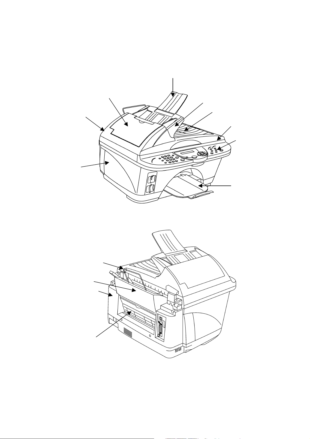
1.1 EQUIPMENT OUTLINE
Front view
3. ADF document support
8. Main cover
Rear view
2. ADF cover
4. Document guide base
5. Document tray
1. ADF
6. Scanner unit
7. Control panel
9. Output paper support
10. Paper support
11. Paper tray
12. Rear cover
13. Manual feed slot
1-1
Page 10

No. Part name Outline of functions
1 ADF
2 ADF cover
3 ADF document support
Automatically feeds the document sheet by sheet to
the reading unit.
Open this cover when removing jammed documents
from the ADF.
Supports the documents fitted to the ADF so that they
do not bend.
4 Document guide base Adjusts the document position to the center of ADF.
5 Document tray Stores the read documents.
6 Scanner unit
7 Control panel
Indicates the whole reading unit including the control
panel. Open this unit when changing the ink cartridge.
Displays the machine operation status and is used to
operate the machine.
8 Main cover Indicates the whole enclosure of the machine.
9 Output paper support Stores the printed sheets of paper.
10 Paper support
11 Paper tray
Supports the paper fitted to the paper tray so that they
do not bend.
Automatically feeds the paper sheet by sheet to the
printing unit.
12 Rear cover
13 Manual feed slot
Indicates the rear enclosure. Open this cover when
doing maintenance work.
Used to feed the paper sheet by sheet manually.
Open the slot cover when removing jammed paper
from the machine.
1-2
Page 11
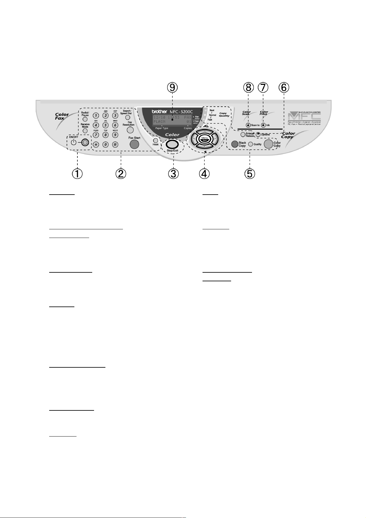
1.2 CONTROL PANEL
ON/OFF
You can turn the MFC on or off.
Fax and telephone keys:
Redial/Pause
Redials the last number you called.
It also inserts a pause in auto dial numbers.
Receive Mode
Use to select how the MFC will handle
incoming calls.
Dial Pad
Use this to dial telephone and fax numbers and
as a keyboard for entering information into the
MFC.
The # key lets you switch the dialing type
during a telephone call from Tone to Pulse
Search/Speed Dial
Lets you look up numbers that are stored in the
Dialing memory. It also lets you dial stored
numbers by pressing # and a two-digit number.
Hook
Lets you dial numbers without picking up the
handset.
Stop/Exit
Stops a fax, cancels an operation or exits from
the Menu.
Navigation keys:
Menu/Set
Lets you access the Menu to program and store
your settings in the MFC.
Press to scroll forward or backward to a menu
selection.
Also, you can use these keys to do an
alphabetical search for the names of stored
numbers.
Volume
Press to scroll through the menus and options.
When using the speaker, you can press these
keys to adjust the volume.
Fax Resolution
Sets the resolution when you send a fax.
Fax Start
Starts an operation, such as sending a fax.
1-3
Page 12

Copy keys (Temporary settings):
Quality
Use this key to temporarily change the quality
for Copying.
Color Print key:
Ink
Lets you clean the print heads, replace an ink
cartridge and check the available ink volume.
Quality indicator lights
These lights show the copy quality you
selected with the Quality key.
Enlarge/Reduce
Lets you enlarge or reduce copies depending
on the ratio you select.
Black Copy
Makes a black-and-white copy.
Color Copy
Makes a full-color copy.
Options
You can quickly and easily select temporary
settings for copying or Photo Capture
TM
Center
.
Scan key:
Scan to
Lets you scan the next original and select the
destination in your computer.
(Such as a Word processing, graphics or E-
mail application, Media card or on a Network.)
Liquid Crystal Display (LCD)
Displays messages on the screen to help you
set up and use your MFC.
1-4
Page 13

CHAPTER
SPECIFICATIONS
2
Page 14

CHAPTER 2 SPECIFICATIONS
CONTENTS
2.1 GENERAL ........................................................................................................................2-1
2.1.1 General Specification ...........................................................................................2-1
2.1.2 Paper Specification ..............................................................................................2-1
2.1.3 Printable Area.......................................................................................................2-3
2.1.4 Environmental Condition ......................................................................................2-4
2.2 OTHERS...........................................................................................................................2-5
Page 15

2.1 GENERAL
2.1.1 General Specification
Memory Capacity
Automatic Document Feeder (ADF) up to 30 sheets (20 lb)
Paper Tray 100 Sheets (20 lb)
Printer Type Ink Jet
Print Method Configuration Piezoelectric ceramic drive with 150 x 4 nozzles
LCD (Liquid Crystal Display) 16 characters x 2 Lines
Operating Environment 50-95ºF (10-35ºC)
Best Print Quality 68-91ºF (20-33ºC)
Power Source 120VAC 50/60Hz (U.S.A., Canadian Version Only)
8MB
240VAC 50/60HZ(Except U.S.A., Canadian Version)
Power Consumption Minimum: under 5 watts
(When Power Switch (ON/OFF) is turned off.)
Standby: under 15 watts
Operating: under 50 watts
Dimensions 19.4 x 18.3 x 14.9 (inches)
492 x 466 x 378 (mm)
Weight 28.6 1b/13 kg
2.1.2 Paper Specification
Recommended paper
Plain Paper: Xerox 4200
Inkjet Paper: KODAK® Premium Inkjet Paper (Matte)
Glossy Paper: JETPRINT PHOTO®
Graphic image paper - Gloss Finish
Transparencies: 3M Transparency Film (CG3410)
2-1
Page 16

Paper capacity and specifications of the Paper Tray
Paper Type Number of sheets Paper Weight Paper Thickness
Letter
Executive
Plain Paper
Legal
Inkjet Paper (Letter) 20
Glossy Paper (Letter) 20
Transparencies (Letter) 10
Envelopes (DL, COM-10, C5,
Monarch)
Postcard 4" x 6" 30
Index Card 5" x 8" 30
Paper stack specifications for the Paper Tray
Paper tray
100 of 20 lb
(80 g/m 2 )
50 of 20 lb
(80 g/m 2 )
10
Up to 0.39 in. (10 mm)
Up to 100 sheets of 20 lb
(80 g/m 2 )
17 to 32 lb
(64 to 120 g/m 2 )
17 to 32 lb
(64 to 120 g/m 2 )
Up to 40 lb
(150 g/m 2 )
Up to 45 lb
(170 g/m 2 )
Up to 32 lb
(120 g/m 2 )
0.003 to 0.006 in.
(0.08 to 0.15 mm)
0.003 to 0.006 in.
(0.08 to 0.15 mm)
Up to 0.007 in.
(0.18 mm)
Up to 0.02 in.
(0.52mm)
Up to 0.009 in.
(0.23 mm)
Up to 0.006 in.
(0.15 mm)
(Transparencies and glossy paper must
Output paper support
Paper specifications for the manual feed slot
Paper Width 3.5 to 8.5 in. (89 to 216 mm)
Paper Height 4 to 14 in. (102 to 356 mm)
Paper Thickness 0.005 to 0.01 in. (0.12 to 0.25 mm)
You have to remove paper from the paper tray and load one sheet at a time.
Up to 50 sheets of 20 lb
(80 g/m 2 )
be picked up from the output paper
support one page at a time to avoid
smudging.)
2-2
Page 17

2.1.3 Printable Area
The printable area depends on the settings in the application you are using. The figures below show the
unprintable areas on cut sheet paper and envelopes.
Paper Paper size Top Bottom Left Right
Fax 0.12 0.47 0.25 0.25
Letter, Legal
Cut sheet
Executive Printer 0.12
Post card 4" x 6" Printer 0.12
Envelopes DL,C5,COM10 Monarch Printer 0.39 0.79 0.12 0.12
* When you set the Near Edge feature to ON.
Printer 0.12
Copy 0.12
0.47
(0.12)*
0.47
(0.12)*
0.47
(0.12)*
0.47
(0.12)*
0.23 0.23
0.23
(0.12)*
0.12 0.12
0.12 0.12
0.23
(0.12)*
Printer depends on the Printer driver.
The figures above are approximate and the printable area may vary depending on the type of cut sheet paper
you are using.
2-3
Page 18
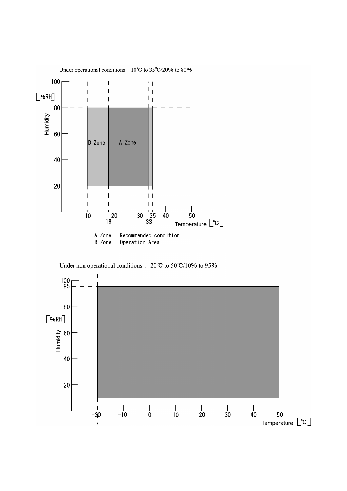
2.1.4 Environmental Condition
2-4
Page 19
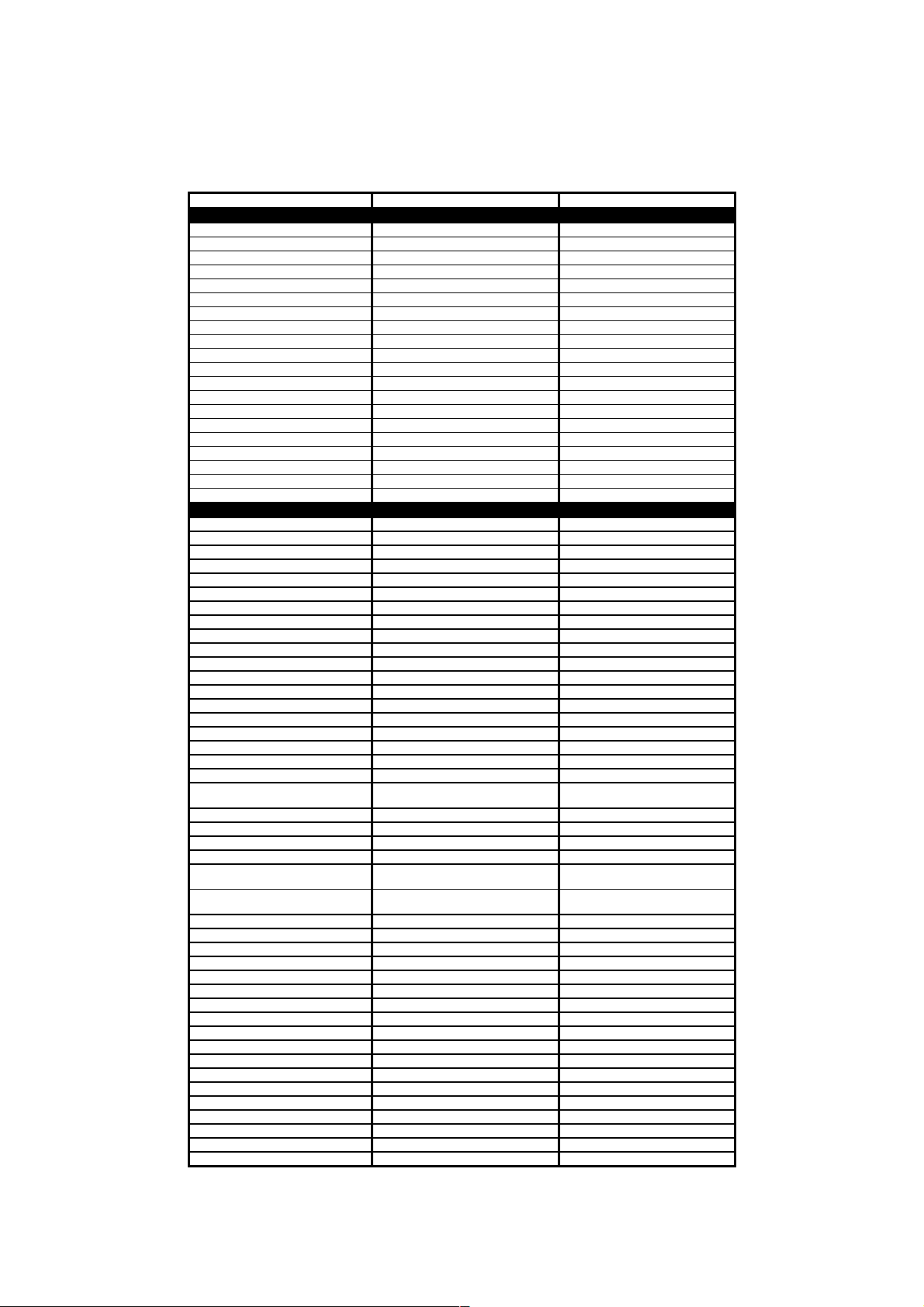
2.2 OTHERS
)
Model Name MFC-5200C MFC-890
TELEPHONE
Automatic Redial Yes(once) Yes
Handset No No
One-Touch Dial 0 0
Speed Dial Max 100 Max 100
Figures of One-Touch & Speed Dial 20 digits 20 digits
Resisterable Number Of Characters 15 char 15 char
Telephone Index Yes(Normal) (TBD) Yes(Normal)
Speaker Phone No(Only Speaker) No(Only Speaker)
Chain Dialing Yes Yes
Caller ID No No
Call Waiting Caller ID No No
Distinctive Ringing Yes Yes
Hold/Mute Key No No
Hook Key Yes TEL/R key (TBD)
Power Failure Dialing No No
Speaker Volume Yes (3 steps + OFF) Yes (3 steps + OFF)
Ring Volume Yes (3 steps + OFF) Yes (3 steps + OFF)
HandSet Volume No No
PBX Feature No Yes
Transfer Method No flash
FAX
Internet FAX LAN Option LAN Option
Data Modem N/A N/A
Easy Receive/Fax Detect Yes Yes
Fax/Tel Switch Yes Yes
Super Fine Yes (Only for Black) Yes (Only for Black)
300dpi Transmission No No
Gray Scale 256 256
Contrast Yes (Auto/S.Light/S.Dark) Yes (Auto/Light/Dark)
Smoothing No No
Call Reservation Over Auto TX No No
Passward Check No No
Enhanced Remote Activate Yes Yes
Multi Resolution Transmission No No
Multi Transmission No No
Next-Fax Reservation Yes (Dual Access) Yes (Dual Access)
Delayed Timer Yes (50 Timer/50 Job) Yes (50 Timer/50 Job)
Polling Yes (Std/Seq) RX/TX Yes (Std/Seq) RX/TX
Quick-Scan key (Memory TX w/o key) (Memory TX w/o key)
Scan Speed (A4:Standard) Approx. 3 sec./page (A4:standard) Approx. 3 sec./page (A4:standard
Memory Transmission(Brother#1
Chart)
Memory Transmission(ITU-T Chart) Yes (400:MMR) Yes (400:MMR)
Broadcasting Yes (150 locations) Yes (150 locations)
Batch Transmission Yes Yes
Auto Reduction Yes Yes
Out-of-Paper Reception (Brother #1
Chart)
Out-of-Paper Reception (ITU-T
Chart)
Dual Access Yes (B&W Only) Yes (B&W Only)
ECM(Error Correction Mode) Yes Yes
ITU SUB Addressing No No
Group Dial Yes (6) Yes (6)
Error Re-Transmission No No
Station ID 1 (20digits/20char) 1 (20digits/20char)
Off Hook Alarm No No
Remote Maintenance Yes Yes
Call Reservation Over Manual TX No No
RX Mode Indication Yes:LCD Yes:LCD
Resolution Indication Yes:LCD Yes:LCD
Memory Security N/A TX Lock
Color FAX (Document nd/Receive) Yes/Yes Yes/Yes
Color FAX (Memory end/Receive) No/Yes No/Yes
Manual Broadcasting Yes Yes
LCD Language English English
Call Manage N/A N/A
E-MAIL FAX(Share Media ervice) N/A N/A
(1/4)
Yes (480:MMR) Yes (480:MMR)
Yes (480:MMR) Yes (480:MMR)
Yes (400:MMR) Yes (400:MMR)
2-5
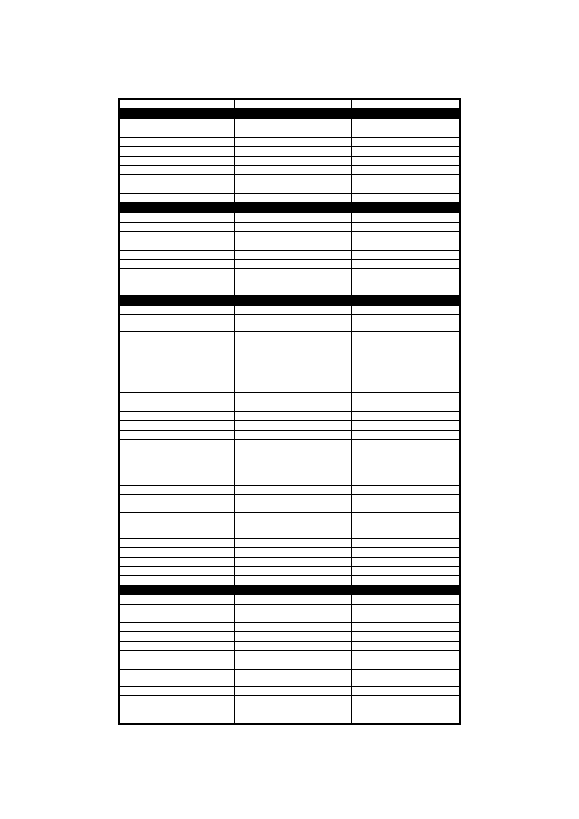
Page 20
(2/4)
Model Name MFC-5200C MFC-890
LIST/REPORT
Activity Report/Journal Report Yes (up to 200) Yes (up to 200)
Transmission Verification Report Yes Yes
Coverpage Yes Yes
Help List Yes Yes (From MENU)
Call Back Message No No
Caller ID List No No
Auto Dial List Yes(From Menu) Yes (From MENU)
Tel Index List N/A N/A
Order Form ( from MFC) N/A YES(FROM MENU)
INTERFACE
External TAD Interface Yes Yes
Missing Link/PC Interface No No
Host Interface (Serial) No No
Host Interface (IEEE1284) Yes Yes
Host Interface (USB) Yes Yes
LAN Interface Option (10Base-T/100Base-TX) Option (10Base-T/100Base-TX)
Acceptable Media Card Slot
Analog Video Port No No
PRINTER
Color/Mono Color/Mono Color/Mono
Engine Type
Resolution(dpi) 2400x1200 /2400x1200 (Mono/Color)
Speed(ppm)
Paper Capacity(sheets) 100 (80gsm) 100(80gsm)
Additional Paper Capacity(sheets) No No
Output Paper Capacity(sheets) 50 50
Standard Print Language Windows GDI Windows GDI
Emulation N/A N/A
Resident Fonts Yes Yes
Fonts Disk Based Yes Yes
Paper Handling Size
Manual Feed Slot Yes (1 sheet feeder) Yes (1 paper feeder)
Other Paper Type OHP, Envelopes OHP, Envelopes
Sheet Weight (Paper Cassette)
(Manual Slot)
Printer Driver
Utility Software N/A N/A
Bundled Cable No No
Variable Dot Print Yes (3 sizes, Min. 5pl) Yes (3 sizes, Min. 5pl)
Shingling Print Yes NO
Color Enhancement Yes (True2Life) Yes (True2Life)
COPY
Color/Mono Color/Mono Color/Mono
Speed(ppm)
Multi Copy(Stack) Yes (Color) or Via PC Yes (Color) or Via PC
Multi Copy(Sort) Yes (Color) or Via PC Yes (Color) or Via PC
Reduction/Enlargement(%) 25 -- 400 in 1% increments 25 -- 400 in 1% increments
Resolution(dpi) Max. 1200x1200 Max. 1200x1200
Resolution Indication LED (Green) -Fast, Normal, Best LED (Green) -Fast, Normal, Best
N in 1 2in1, 4in1/ B&W, Color: A4, LTR only
Poster Yes Yes
Clone N/A N/A
Image Enhancement N/A N/A
Book Copy Supporter N/A N/A
Smart Media/Compact Flash/Memory
Piezo Ink Jet (4 head BH: 150
20/16 (Mono/Color: 450*150)
'10/7 (Mono/Color: 600*300)
'3.5/2.5 (Mono/Color: 600*600)
'1.2/0.9 (Mono/Color: 1200*1200)
'0.6/'0.4(Mono/Color:2400*1200)
Post Card, Photo, Index card
105-185g/m2 (28-49.3 lb)
Win95/98/98SE/Me/2000Professinal/
12/8 (Multiple documents)
Stick
nozzles/color)
LTR, LGL, A4, A5, EXE,
64-120 g/m2 (17 - 32 lb)
NT4.0/XP
MacOS 8.5.1-10.1
15/12 (Multiple copies)
Smart Media/Compact
Flash/Memory Stick
Piezo Ink Jet (4 head BH: 150
nozzles/color)
1200x1200 /2400x1200
(Mono/Color)
20/16 (Mono/Color: 450*150)
'10/7 (Mono/Color: 600*300)
'3.5/2.5 (Mono/Color: 600*600)
'1.2/0.9 (Mono/Color: 1200*1200)
'0.4(Color:2400*1200)
LTR, LGL, A4, A5, EXE,
Post Card, Photo, Index card
64-240 g/m2 (17 - 64 lb)
Win95/98/98SE/Me/2000Professin
12/8 (Multiple documents)
2in1, 4in1/ B&W,color: A4, LTR
Yes
al/NT4.0/XP
MacOS 8.5.1-10.1
15/12 (Multiple copies)
only
2-6
Page 21

(3/4)
Model Name MFC-5200C MFC-890
SCANNER
Color/Mono Color/Mono Color/Mono
Resolution(dpi)(Phisical) CCD: 600x2400(Opt.) CCD: 600x2400(Opt.)
Resolution(dpi) (Logical) 9600(Int.) 9600(Int.)
Speed(ppm) Max. 3sec Max. 3sec
Gray Scale 256 256
TWAIN Compliant&Operating
System
PCI Scanner (Parallel/Serial) Parallel/ USB Parallel/ USB
E-MAIL Scan Key No No
OCR Scan Key No No
Scan Key
Color Depth 36bit-color processing (24bit external)
Pre Feeding No No
Consecutive feeding on ADF Yes (Windows&Mac) Yes (Windows&Mac)
MESSAGE CENTER/MESSAGE MANAGER
ICM Recording Time N/A N/A
Page Memory N/A N/A
OGM (MC;MC Pro;Paging;F/T) N/A N/A
TAD Type N/A N/A
Memo/Recording Conversation N/A N/A
Fax Forwarding Yes (B&W only) Yes (B&W only)
Fax Retrieval Yes (B&W only) Yes (B&W only)
Paging Yes Yes
Remote Access Yes Yes
Toll Saver N/A N/A
MESSAGE CENTER Pro/MESSAGE MANAGER Pro
Fax/Voice Mail Box N/A N/A
Fax/Voice on Demand N/A N/A
MESSAGE CENTER (PC MC)
Fax Forwarding N/A N/A
Paging N/A N/A
ICM Recording Time N/A N/A
OGM MC;MC Pro;Paging N/A N/A
Fax/Voice Mail Box N/A N/A
Fax/Voice on Demand N/A N/A
VIDEO CAPTURE
Video Capture N/A N/A
Video Print N/A N/A
Video Format N/A N/A
Video Fax N/A N/A
PHOTOCAPTURE CENTER
Acceptable Media
Print Yes(Color) Yes(Color)
Media format DPOF, Exif, DCF DPOF, Exif, DCF
Image format TIFF/JPEG/PDF (Scan-to-Card) TIFF,JPEG,PDF(scan-to-card)
Color Enhancement Yes Yes
Media Drive Yes (USB Only)
Win95/98/98SE/Me/2000Professinal/
NT4.0/XP(WIA)
MacOS 8.6-9.2
Yes (Windows Only) + Scan-to-
Image/OCR/
E-mail/Card
Smart Media (3.3V)
Compact Flash (Type-1/2)
Memory Stick
Win95/98/98SE/Me/2000Professin
Yes(Windows Only)+scan-to-
Yes (USB Only) Win98/98Se/ME/
al/NT4.0/
XP (WIA)/MacOS 8.6-9.2
Image/
OCR/E-mail/Card/LAN
36bit-color processing (24bit
external)
Smart Media (3.3V)
Compact Flash (Type-1/2)
Memory Stick
2000/XP/Mac9.0-10.1
2-7
Page 22

Model Name MFC-5200C MFC-890
Network Specifications
Standard/Option Option Option
Model Name NC-8100h NC-8100h
Support OS version Win95/98/98SE/Me,WinNT4.0/2K
Support OS version Novell NetWare 3.X,4.X,5.X Novell NetWare 3.X,4.X,5.X
Network connection
Support Protocols
TCP/IP Protocols
TCP/IP Protocols LPR/LPD, Port9100, SMTP/POP3 LPR/LPD, Port9100, SMTP/POP3
TCP/IP Protocols SMB(NetBIOS/ IP), IPP, FTP SMB(NetBIOS/ IP), IPP, FTP
TCP/IP Protocols TELNET, SNMP, HTTP, TFTP TELNET, SNMP, HTTP, TFTP
Network Management BRAdmin Professional BRAdmin Professional
Network Management Web Based Management (Reading) Web Based Management (Reading)
Network Management MIB-II as well as Brother private MIB MIB-II as well as Brother private MIB
Format (Scan to LAN) JPEG/PDF/TIFF JPEG/PDF/TIFF
BUNDLED SOFTWARE (For Windows)
Printer Driver Brother Brother
TWAIN Brother Brother
Veiwer Scan Soft Scan Soft Paper Port 8.0 (Win95-XP)
PC Fax
Others N/A N/A
Formats(Import)
Formats(Export)
OCR Yes(ScanSoft TextBridge) Yes(ScanSoft TextBridge)
Pop Up Menu Yes Yes
Remote Setup Yes Yes
PC Diagnostics Yes Yes
BUNDLED SOFTWARE (For iMAC/iBook/G3/G4)
Printer Driver Brother Brother
TWAIN Brother
Veiwer Scan Soft (Mac OS8.6) No
PC Fax
Others No No
Formats(Import) - Formats(Export) - OCR MacOS 8.6 No
Pop Up Menu No No
Remote Setup Yes(MacOS Xv.10.1) Yse (OS Xv.10.1)
PC Diagnostics No No
ACCESSORY
Cartridge 4 colors (each separate tank) 4 colors (each separate tank)
Life / Yield (Draft, 5%
Coverage)
cable No No
Ethernet 10/100BASE-TX Auto
RARP, BOOTP, DHCP, NetBIOS,
Win95/98/98SE/Me/2000Professinal/N
MAX/BMP/PCX/DCX/JPG/TIF/PNG/FPXMAX/BMP/PCX/DCX/JPG/TIF/PNG/FP
MAX/HTM/BMP/PCX/DCX/JPG/TIF/PN
Brother PC Fax (B&W Sending)
Negotiation
TCP/IP, IPX/SPX, AppleTalk,
DLC/LLC
WINS
Brother PC Fax (B&W
Sending/Receiving)
T4.0/XP
G/FPX
MacOS 8.5.1-9.2
BK: 950, CL: 450 BK: 950, CL: 450
Win95/98/98SE/Me,WinNT4.0/
2000Professional/XP
Ethernet 10/100BASE-TX Auto
RARP, BOOTP, DHCP, NetBIOS,
Win95/98/98SE/Me/2000Professinal/N
MAX/HTM/BMP/PCX/DCX/JPG/TIF/PN
Brother PC Fax (B&W Sending)
Negotiation
TCP/IP, IPX/SPX, AppleTalk,
DLC/LLC
WINS
Brother PC Fax (B&W
Sending/Receiving)
T4.0/
XP(Microsoft PC-Fax)
X
G/FPX
Brother
Mac OS 8.6-9.2
MacOS 8.5.1-9.2
(4/4)
2-8
Page 23

CHAPTER
INSTALLATION
3
Page 24

CHAPTER 3 INSTALLATION
CONTENTS
3.1 CONDITIONS REQUIRED FOR INSTALLATION........................................................... 3-1
3.1.1 Environmental Conditions ....................................................................................3-1
3.1.2 Basic Layout of machine Set-up Location............................................................3-1
3.2 UNPACKING THE MACHINE..........................................................................................3-2
3.3 INSTALLATION WORK...................................................................................................3-3
3.3.1 Removing the Protective Parts.............................................................................3-3
3.3.2 Attaching the Paper Supports ..............................................................................3-4
3.3.4 Install Phone Line and Power Cord......................................................................3-5
3.3.5 Installing the Ink Cartridges..................................................................................3-6
3.3.6 Color Block Quality and Alignment Check............................................................ 3-8
Page 25
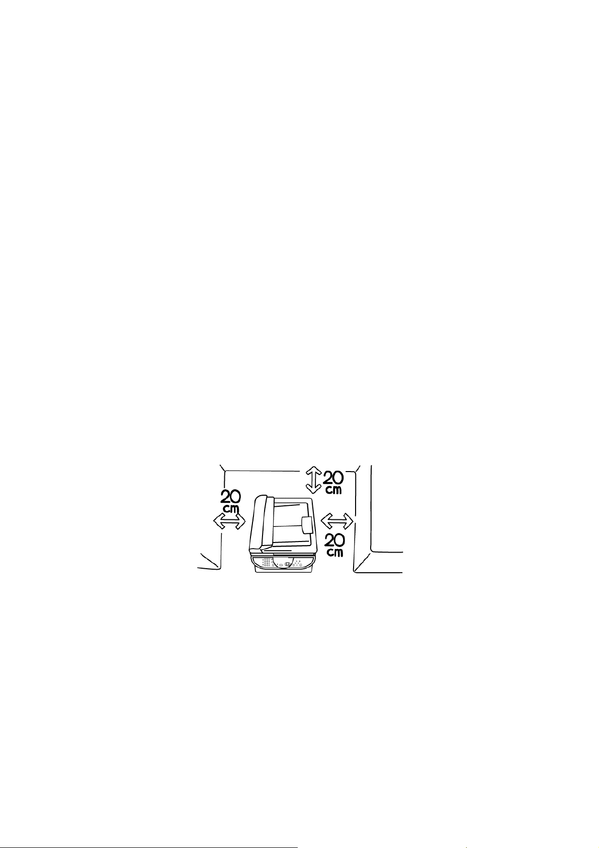
3.1 CONDITIONS REQUIRED FOR INSTALLATION
Any machine is likely to be influenced by the environment of the set-up location. If the machine is
set-up in an inappropriate location, the machine may not perform as expected. Therefore, the
following factors should be taken into consideration before deciding where to set-up the machine.
3.1.1 Environmental Conditions
The machine should not be set up in the locations referred to in the following items (a) through (d)
which specify inappropriate locations for set-up.
(a) Where it is likely to receive direct sunlight or similar light. (For example, next to a window)
(b) Where it is likely to suffer a big difference in temperature and humidity between the
maximum and minimum levels. (Normal operation environment is within 10 ˚C to 35 ˚C, 20 to
80%RH and without any condensation.)
(c) Where it is likely to be in a draft of cold air from an air-conditioner or warm air from a heater,
or to receive direct radiant heat.
(d) Where it is likely to be excessively dusty or be subject to corrosive gases such as ammonia.
(e) Users should select a location with good ventilation and set the machine on a flat surface.
(f) Users should check that the maximum angle of the set-up location is horizontal to within 1 ˚ .
3.1.2 Basic Layout of machine Set-up Location
Shows the basic layout of the machine set-up location that is suitable for smooth.
3-1
Page 26
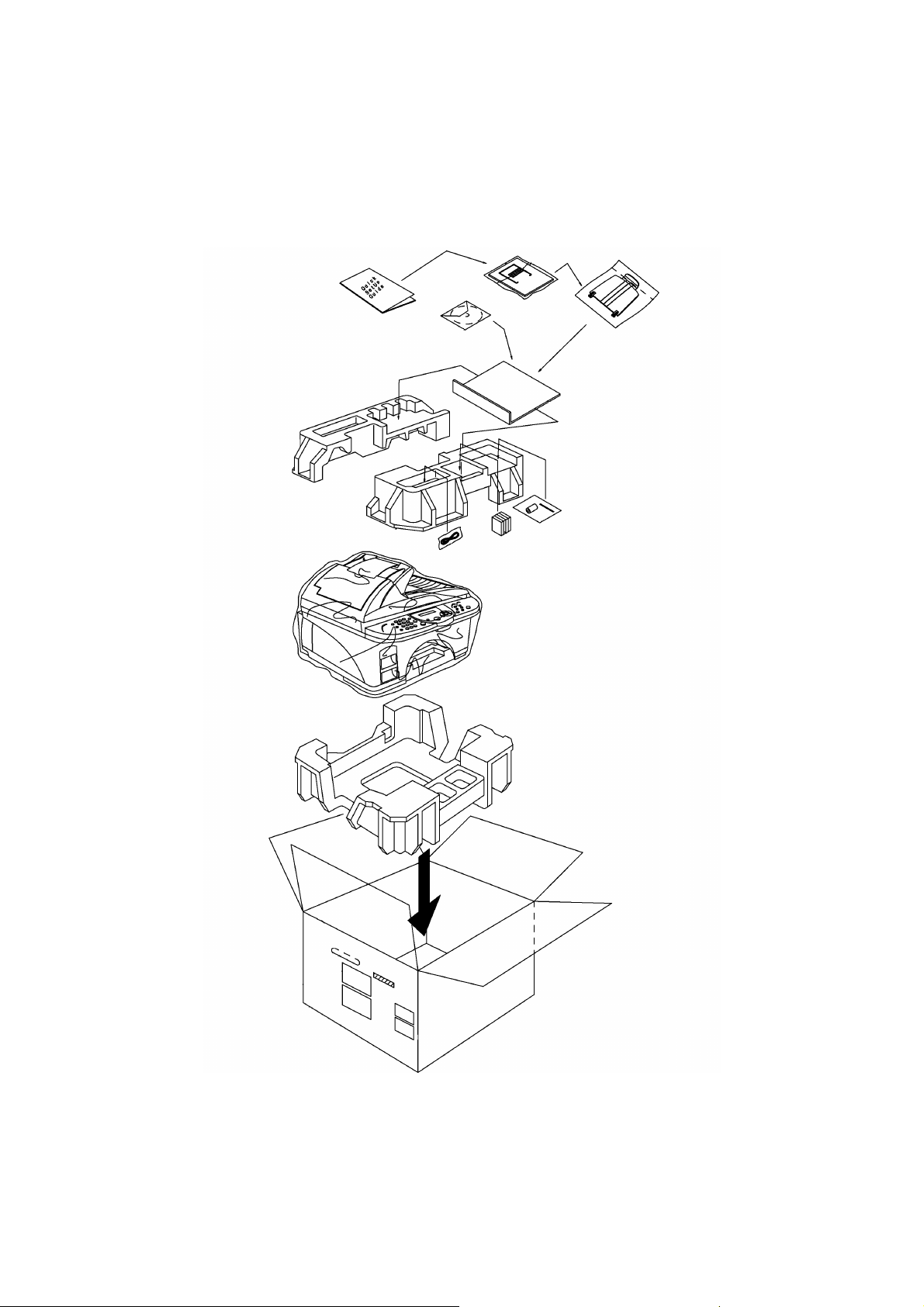
3.2 UNPACKING THE MACHINE
The equipment consists of the following major components:
3-2
Page 27
3.3 INSTALLATION WORK
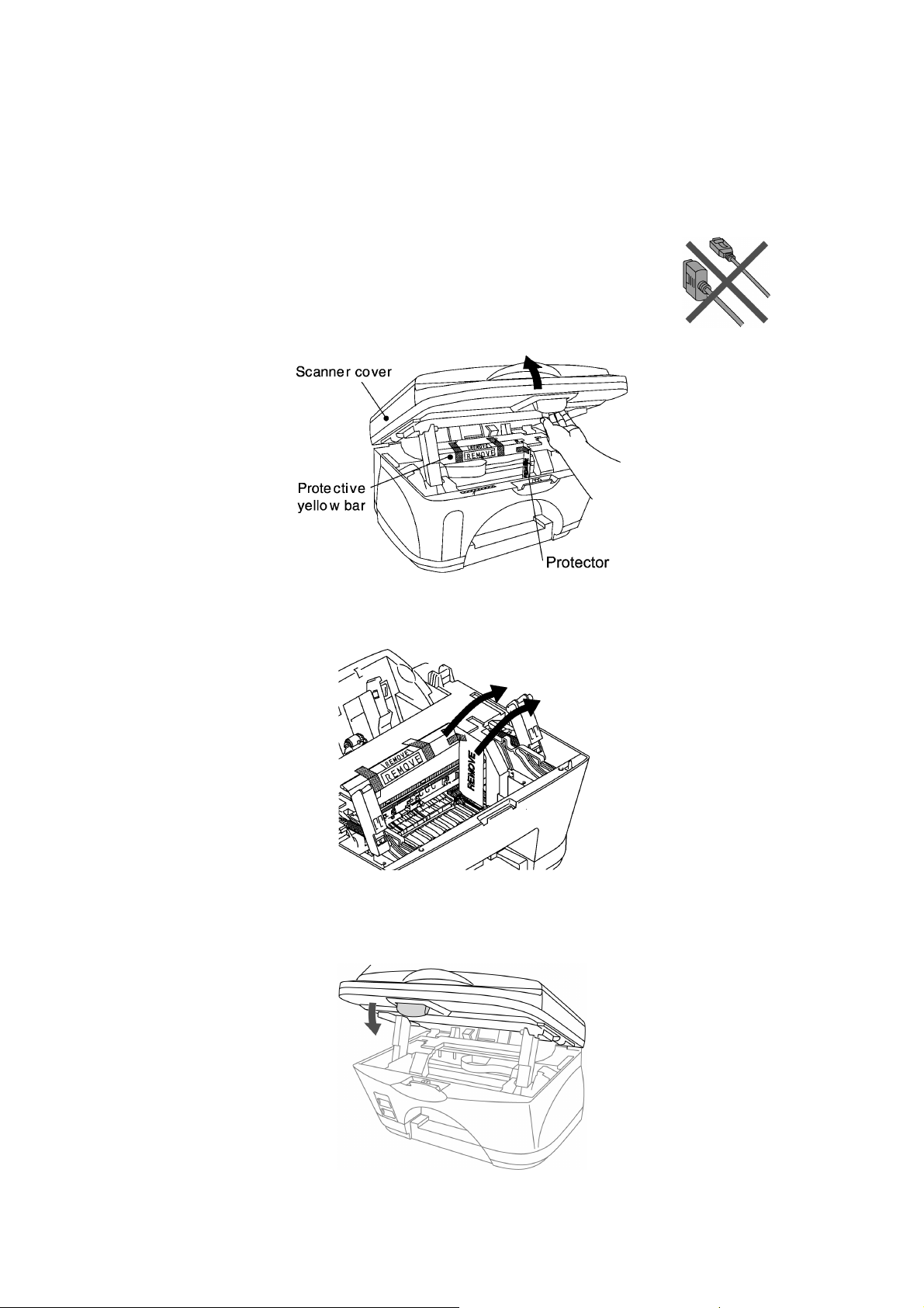
3.3.1 Removing the Protective Parts
Do NOT connect the interface cable.
Connecting the interface cable is done when installing the driver.
(1) Remove the protective seals.
(2) Open the scanner cover by pulling the release lever towards you.
(3) Remove the protector and the protective yellow bar.
Do not throw away the protective yellow bar. You will need it in the future to transport the
machine.
(4) Close the scanner cover.
3-3
Page 28
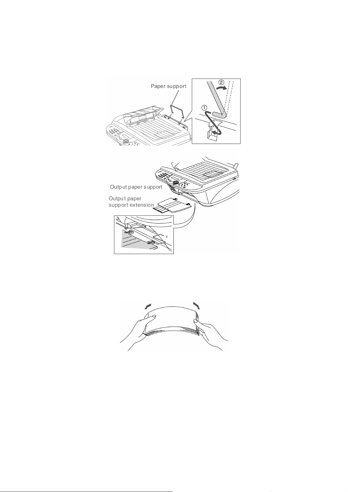
3.3.2 Attaching the Paper Supports
(1) Attach the paper support to the paper tray.
(2) Attach the output paper support to the paper output slot, and then pull out the extension.
3.3.3 Load Paper
(1) Fan the stack of paper well to avoid paper jams and misfeeds.
3-4
Page 29
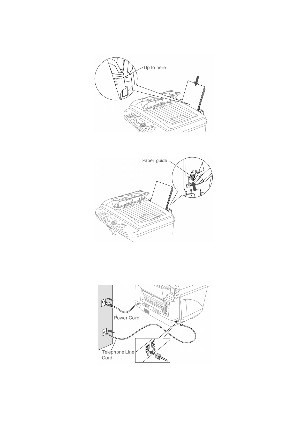
(2) Gently insert the paper.
Make sure the print side is towards you and the paper is below the maximum paper mark.
(3) Press and slide the paper guide to fit the paper width.
3.3.4 Install Phone Line and Power Cord
(1) Connect the power cord.
(2) Connect one end of the telephone line cord to the jack on the machine marked LINE and the
other end to a modular wall jack.
3-5
Page 30
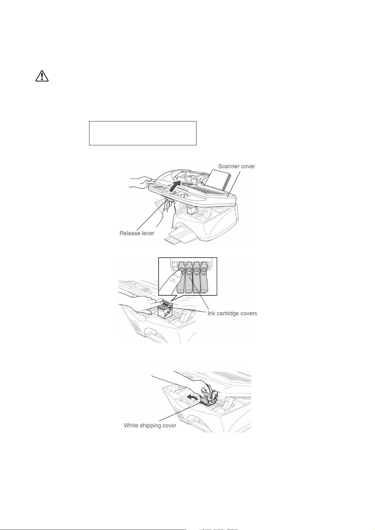
3.3.5 Installing the Ink Cartridges
WARNING
If ink gets in your eyes irrigate them with water immediately, and if irritation occurs consult a doctor.
(1) Make sure that the power is turned on.
The LCD shows;
CHECK CARTRIDGE
Open cover, then...
(2) Open the scanner cover by pulling the release lever towards you.
The print heads will move to the ink replacement position.
(3) Push the four colored ink cartridge covers one at a time so they pop up.
(4) Remove the white shipping cover by pulling it towards you.
The bottom of the white shipping cover is wet with ink that will cause stains, so wipe it clean
before you place it down.
Do not throw away the white shipping cover. You will need it when you transport the
machine.
3-6
Page 31

(5) Take out black ink cartridge.
(6) Carefully remove the sealing tape from the bottom of the ink cartridge.
To prevent spilling ink and staining your hands and clothing, peel the sealing tape gently and
slowly.
Do not touch the ink opening on the cartridge or removed tape.
(7) Gently insert the black ink cartridge in the black ink position.
(8) Press the cover down until it clicks.
(9) Repeat Steps 5 to 8 to install each color ink cartridge. Match the colors of the ink cartridge
covers.
3-7
Page 32

(10) Close the scanner cover. The MFC will enter a head cleaning cycle for approximately six
minutes.
CLEANING
PLEASE WAIT
• DO NOT remove ink cartridges if you do not need to replace them.
If you do so, it may reduce the ink quantity and the MFC will not know the quantity of ink
left in the cartridge.
• DO NOT shake the ink cartridges.
If you do so, the ink may spill when you take off the sealing tape. If ink stains your body or
clothing, wash with soap or detergent immediately.
• DO NOT refill the ink cartridges.
Attempting to use refilled cartridges and using incompatible inks may cause damage to the
print head in this machine and such damage will not be covered by warranty.
Warranty coverage does not apply to problems caused by the use of 3rd party ink or 3rd
party ink cartridges. Use only genuine Brother ink cartridges.
If you mix the colors by installing an ink cartridge in the wrong color position, you must clean
the print head several times after correcting the cartridge installation and before you start
printing.
Once you open an ink cartridge, install it in the machine and use it up within six months of
installation. Use unopened ink cartridges by the expiration date written on the cartridge
package.
If INK EMPTY shows on the LCD after you install the ink cartridges, check to make sure the
ink cartridges are installed correctly.
3.3.6 Color Block Quality and Alignment Check
(1) After the cleaning cycle is finished, the LCD shows;
SET PAPER AND
PRESS FAX START
(2) Make sure the paper is loaded in the paper tray.
Press the Fax Start key.
(3) The MFC starts printing the PRINT QUALITY CHECK SHEET (only during initial ink
cartridge installation).
3-8
Page 33

Step A: Color Block Quality Check
y
y
f
r
Step B: Alignment Check
1. The LCD shows:
IS STEP "A"OK?
1. YES 2.NO
Check the quality of the four color blocks printed
on the sheet. (BLACK/CYAN/YELLOW/
MAGENTA)
2. If the quality is OK for all colors, press the "1"
key on the dial pad to go to STEP B: Alignment
Check.
---OR---
If white horizontal lines appear in some of the color
blocks, press the "2" key on the dial pad and go to
3.
The LCD shows:
IS STEP "B"OK?
1. YES 2.NO
Check the 600 DPI and 1200 DPI test print to see i
No.5 most closely matches the OK sample (No.0).
Press the "1" key if No.5 matches it.
3. The LCD asks you if the print quality is OK for
each color. Press the "1" key or "2" ke
dial pad.
on the
2 BLACK OK?
1.YES 2.NO
When you have finished selecting the "1" ke
(YES) or the "2" key (NO) for magenta, the LCD
shows:
START CLEANING?
1.YES 2.NO
Press the "1" key (YES), and then machine starts
cleaning the colors.
After cleaning is finished, press the Fax
Start key. The machine starts printing PRINT
QUALITY CHECK SHEET again and goes back to
the first step of STAP A.
If another test print number is a better match fo
either 600 DPI or 1200 DPI, press the "2" key to
select NO and go to 2.
2. For 600 DPI, select the number from 1 to 8
that most closely matches the No.0 sample
and enter it using the dial pad.
600DPI ADJUST
SELECT BEST #
3. For 1200 DPI, enter the number from 1 to 8
that most closely matches the No.0 sample.
1200DPI ADJUST
SELECT BEST #
The quality check is now complete.
3-9
Page 34

CHAPTER
THEORY OF OPERATION
4
Page 35

CHAPTER 4 THEORY OF OPERATION
CONTENTS
4.1 OVERVIEW ......................................................................................................................4-1
4.2 MECHANISMS .................................................................................................................4-2
4.2.1 Scanner Mechanism ............................................................................................4-4
4.2.2 Ink Jet Printing Mechanism ..................................................................................4-6
4.2.2.1 Paper pulling-in, registration, feeding, and ejecting mechanisms................4-6
4.2.2.2 Ink jet printing and capping mechanisms.....................................................4-8
4.2.2.3 Purging mechanism ...................................................................................4-11
4.2.2.4 Carriage drive mechanism .........................................................................4-14
4.2.3 Sensors and Actuators.......................................................................................4-15
4.3 CONTROL ELECTRONICS ...........................................................................................4-18
4.3.1 Configuration......................................................................................................4-18
Page 36

4.1 OVERVIEW
Host
Compact Flash
SmartMedia
Memory Stick
Line
Control
panel
NCU
Fax Control Section
ADF unit
- ADF motor
Speaker
Scanner unit
- CCD unit
- CCD motor
Centronics
parallel
interface
Print data
Ink jet printer unit
- Ink jet print head
unit
- Carriage motor
- Carriage ASSY
- Purge unit
USB
interface
Printer Control Section
Paper feeding
mechanism
- Paper feed
motor
Media
station
Power
supply
AC
4-1
Page 37

4.2 MECHANISMS
The facsimile machine is classified into the following mechanisms:
SCANNER MECHANISM - ADF mechanism
INK JET PRINTING MECHANISM - Paper pulling-in, registration, feeding, and ejecting
SENSORS AND ACTUATORS
- Document scanning mechanism
mechanisms
- Ink jet printing and head capping mechanisms
- Purging mechanism
- Carriage drive mechanism
4-2
Page 38

SCANNER MECHANISM
4-3
Ink jet printing and head
capping mechanisms
Purge mechanism
Carriage drive mechanism
Paper pulling-in,
registration, feeding, and
ejecting mechanisms
INK JET
PRINTING
MECHANISM
Page 39

4.2.1 Scanner Mechanism
This mechanism consists of the document guide base, ADF & document cover ASSY and scanner
unit.
The ADF (automatic document feeder) unit contains a separation roller ASSY, document feed
roller ASSY, document ejection roller, ADF motor, and document front and rear sensors.
The scanner unit consists of a scanner top cover, CCD unit, CCD drive mechanism, CCD HP
sensor, and scanner base.
For details about the sensors, refer to Subsection 4.2.3.
Document ejection roller
ADF motor
Document guide base
Document cover
ADF & document cover ASSY
Document feed roller
Separation roller ASSY
CCD drive belt
CCD motor
CCD unit
CCD rail
Scanner top cover
Scanner unit
CCD flat cable
CCD HP sensor
Scanner base
4-4
Page 40

This scanner mechanism supports a dual scanning system.
(1) If you set documents on the document guide base with their faces up and start the scanning
operation, then the ADF motor rotates to pull in those documents into the ADF unit, starting
from the top sheet to the bottom, page by page. Each document curves downwards and turns to
the right with the document feed roller so as to advance above the CCD unit, and then it is fed
out to the document cover with the document ejection roller ASSY.
This way, documents move above the CCD unit being kept in a stationary position.
(2) If you open the ADF & document cover ASSY, put a sheet of document with its face down (or
put a bound book opened) on the glass of the scanner top cover, close the ADF & document
cover ASSY, and start the scanning operation, then the CCD drive mechanism will be driven.
The CCD motor built in the CCD unit rotates. As illustrated below, the CCD drive gear and
idle pulley carry the CCD drive belt on the underside of the CCD unit, so clockwise and
counterclockwise rotations of the CCD motor move the CCD unit to the right and left,
respectively.
In this scanning system, the CCD unit moves horizontally beneath a document being kept in
stationary position.
CCD drive belt
Underside of the
CCD unit turned
upright
CCD unit
turned upright
CCD motor
gear
CCD idle pulley
Scanner base
CCD drive gear
The CCD unit contains a charge coupled device (CCD) image sensor. The cold-cathode
fluorescent lamp illuminates a document and the reflected light of the scanned image data is
transmitted via the mirrors into the lens which reduces the scanned data so as to form the image on
the CCD.
4-5
Page 41

4.2.2 Ink Jet Printing Mechanism
4.2.2.1 Paper pulling-in, registration, feeding, and ejecting mechanisms
The paper pulling-in, registration, feeding, and ejecting mechanisms are driven by a single paper
feed motor located at the left side of the main chassis via the two PF timing belts and gear train.
(See the illustration given on the next page.)
First, the paper feed motor rotates counterclockwise (when viewed from the output gear). The
rotation is transmitted via the PF timing belt L to the PF roller pulley that rotates the paper feed
roller. At the right end of the paper feed roller is the PF roller gear R which is always engaged with
the ASF/purge idle gear. Engaged with the ASF/purge idle gear, the ASF-purge switching gear 23
transmits the rotation via gear 25 and ASF gear train to the ASF roller ASSY. This way, the ASF
roller will pull in paper.
When the ASF roller is pulling in paper, the paper feed roller rotates in the backward direction to
register the leading edge of the pulled-in paper.
Next, the paper feed motor rotates clockwise to rotate the paper feed roller in the forward
direction. The paper will advance through the paper path. During the paper feeding operation, no
rotation is transmitted to the ASF roller because of the planetary gear system built in the ASF
roller ASSY.
The above paper pulling-in and feeding operations take place when the carriage is in printing
operation. If the carriage reaches the purge position, the ASF-purge switching gear 23 will be
disengaged from the gear 25 and engaged with purge bevel gear A. For the purging mechanism,
refer to Subsection 4.2.2.3.
Paper pulling-in
mechanism
Registration &
paper feeding
mechanisms
ASF
ASF roller
ASSY
Paper width sensor
actuator
Registration
sensor actuator
Paper pressure
holders
Paper chute
Paper feed roller
Recording paper
(Carriage)
(Carriage rail)
(Ink cartridges)
Platen
(Print head unit)
Star wheels
Paper ejection
roller
Paper ejecting
mechanism
4-6
Page 42

ASF
ASF roller ASSY
PF timing belt L
PF roller pulley L
ASF shaft
Paper feed roller ASSY
Gear 25
ASF-purge switch gear 23
ASF/purge idle gear
PF roller gear R
Tension plate R
PF timing belt S
Ejection roller pulley
Tension plate F
Paper ejection roller ASSY
Paper feed motor
4-7
Page 43

4.2.2.2 Ink jet printing and capping mechanisms
Carriage encoder
Carriage
motor
Carriage rail
(1) Print head unit
Main chassis
Platen
Carriage PCB
Ink cartridge sensors
Ink cartridges
Ink empty sensor
Carriage
(Star wheels)
(Paper ejection roller)
Print head unit
This machine uses drop-on-demand ink jet printing. The print head has four ink-jet units for four
color inks. Each of those units consists of 150 nozzles, 150 channels covered with piezoelectric
ceramic (PZT), a manifold, and filter. As illustrated below, the pair of nozzle columns is staggered.
Paper feed direction
77/150"
(13.0387 mm)
Carriage travel direction
1/150"
(0.1693 mm)
#1
#2
#149
#150
Black Cyan Yellow Magenta
Ink-jet units
1/150"
(0.1693 mm)
1/75"
(0.3387 mm)
74/75"
(25.0613 mm)
Nozzle Layout (viewed from the bottom)
4-8
Page 44

If the controller issues a print command, a biased voltage will be applied to all electrodes formed
on the surface of the piezoelectric ceramic so that each actuator will be distorted as shown with
broken lines.
If the electrodes on a target channel are deenergized according to drive signals, then the associated
piezoelectric ceramic actuator returns to the previous form so that the ink in the manifold will be
vacuumed out to the channel.
If the voltage is applied again, the piezoelectric ceramic actuator will be distorted again to apply
pressure to the ink in the channel, causing the ink to jet out through the nozzle. The jetted-out ink
drop will be splashed and produce a dot on paper held by the platen.
As the carriage holding the print head unit travels at the printing speed, the controller sends print
command pulses to the piezoelectric actuator driver circuit embedded in the print head unit.
(2) Ink cartridges
The machine uses four ink cartridges (black, cyan, yellow, and magenta) of disposable type to
supply ink to the print head unit. As shown below, an ink cartridge contains an ink-impregnated
urethane foam. If ink-jet print operation or purging operation takes place, ink comes out of the
urethane foam and is supplied to the print head unit through the ink room, filters, and manifold.
For the ink cartridge sensors on the carriage PCB, refer to Subsection 4.2.3.
4-9
Page 45

(3) Head caps
Shown below is a head cap mechanism that prevents the nozzles of the print heads from drying up
when they are not in use.
Upon completion of printing, the carriage travels to the right and moves the head cap holder
provided on the purge unit to the right together. In the head cap holder is a head cap unit which is
supported with a lift lever. The rightward movement of the head cap holder turns the lift lever and
pushes up the head cap unit to the position where the head caps come into tight contact with the
print heads. This way, the nozzles will be capped.
4-10
Page 46

4.2.2.3 Purging mechanism
The purge mechanism is driven by the paper feed motor located at the left side of the main chassis.
As described in Subsection 4.2.2.1, the motor rotation is transmitted to the ASF/purge idle gear at
the right side of the main chassis. Engaged with the ASF/purge idle gear, the ASF-purge switching
gear 23 works as a clutch gear.
When the carriage travels from the left to right to reach the purge position, the tab provided on the
back of the carriage pushes the purge lever on the main chassis to the right (see the illustration
below). Accordingly, the ASF-purge switching gear 23 (which was shifted to the left by the purge
lever) will move to the right by the switching gear spring so as to become disengaged from the
gear 25 and engaged with the purge bevel gear A. (See the illustration given on the next page.)
This engagement will transmit the motor rotation to the purge bevel gear B on the purge unit. This
way, when the carriage is in the purge position, the motor rotation is transmitted to the purge unit.
On the contrary, if the carriage travels from the purge position to the left, the tab on the back of the
carriage releases the purge lever which will be pulled back to the left. The ASF-purge switching
gear 23 will be disengaged from the purge bevel gear A.
4-11
Page 47

During printing: The ASF-purge switching gear 23 is
not engaged with purge bevel gear A (but engaged with
gear 25 in the ASF gear train).
During purging: The ASF-purge
switching gear 23 is engaged with
purge bevel gear A.
When the motor rotation is transmitted to the purge unit, its counterclockwise rotation will drive
the purge cam and its clockwise rotation, the pump switching unit (when viewed from the output
gear of the motor).
When the paper feed motor rotates counterclockwise
When the paper feed motor rotates clockwise
4-12
Page 48

The purge cam is so designed that:
- the carriage lock pops out to lock the carriage before purging and pops in before cleaning with
the head wiper (see the illustration below),
- the pump works to draw out ink from each of the four head nozzles and drain it to the ink
absorber felts, and
- the head wiper comes out to clean the nozzle surface (see the illustration below).
The pump switching cam is so designed that:
- the pump switching unit switches application of the pump's negative pressure between the four
head nozzles in the order of black, cyan, yellow, and magenta nozzles. When the pump
switching cam is in the home position, normal atmospheric pressure will be restored.
The home position of the purge cam and pump switching cam are detected by their HP switches.
For those switches, refer to Subsection 4.2.3.
(1) Carriage lock
If the purge cam is driven, the carriage lock of the purge unit pops out and locks the carriage to
align ink-jet units with the mating head caps during purge operation. After purging but before
cleaning with the head wiper, it pops in to release the carriage. When the power is off, the carriage
lock keeps the print heads pressed against the head caps.
(2) Purging
If activated, the pump draws out ink to purge air bubbles or dust from the inside of the head
nozzles and channels. As the purge cam rotates by one turn, the piston of the pump reciprocates
two strokes. To complete purging of all four nozzles and channels, the purge cam rotates by two
turns ad the piston reciprocates four strokes.
(3) Draining
The pump drains drawn ink into the ink absorber felts.
(4) Cleaning with the head wiper
After purging operation, the head wiper comes out and the carriage moves from the right to left so
as to clean ink remaining on the heads' surface.
(5) Restoring the pump's pressure to normal atmospheric pressure
When the pump switching cam is in the home position, the controller stops to produce negative
pressure and restore the pump's pressure to normal atmospheric pressure.
Carriage lock
Head wiper
(Rear)
Purge unit
Purge cam
4-13
Page 49

4.2.2.4 Carriage drive mechanism
The carriage motor controls horizontal motion. The motor rotation is transmitted via the motor
pulley to the carriage timing belt.
The carriage, which is supported and guided by the carriage rail, is secured to the timing belt.
Clockwise and counterclockwise rotations of the carriage motor move the carriage to the right and
left, respectively.
On the back of the carriage is the carriage encoder which tells the control circuitry the current
carriage position counted based on the carriage motor position by using the encoder strip attached
to the main chassis.
Main chassis
Carriage timing belt
Idle pulley
Carriage
Carriage encoder
Encoder strip
Carriage rail
Carriage motor
Motor pulley
4-14
Page 50

4.2.3 Sensors and Actuators
This machine has the following sensors and thermister.
Sensor name Type Located on
Document front sensor Photosensor
Document rear sensor Photosensor
Document sensor PCB in
the ADF
Document cover open sensor Mechanical switch Document cover
Scanner open sensor Photosensor Control panel PCB ASSY
Registration sensor Photosensor Driver PCB
Paper width sensor Photosensor Driver PCB
Manual feed slot cover sensor Mechanical switch ASF
CCD HP sensor Photosensor CCD PCB on the CCD unit
Ink empty sensor Photosensor Sensor support
Ink cartridge sensors Mechanical switches
Carriage encoder Photosensor
Carriage PCB
Head thermister Thermister
Purge cam HP switch Mechanical switch
Purge unit
Pump switching cam HP switch Mechanical switch
• Document front sensor which detects the presence of documents.
• Document rear sensor which detects the leading and trailing edges of pages to tell the control
circuitry when the leading edge of a new page has reached the starting position and when the
scan for that page is over.
• Document cover open sensor which detects whether the document cover is closed.
• Scanner open sensor which detects whether the scanner unit is closed.
• Registration sensor which detects the leading and trailing edges of paper, which allows the
controller to determine the registration timing and check paper jam.
• Paper width sensor which detects whether the paper width is "A4-size or wider" or "narrower
than A4-size."
• Manual feed slot cover sensor which detects whether the manual feed slot cover is closed.
• CCD HP sensor which detects whether the CCD unit is placed in the home position.
• Ink empty sensor which detects at the start of printing whether any of the four ink cartridges is
near empty. According to this sensor signal, the controller may display "NEAR EMPTY XXX"
message.
• Ink cartridge sensors, each of which detects whether an ink cartridge is loaded.
• Carriage encoder which detects the current carriage position and carriage travel speed. If the
carriage travels speed varies abnormally, the controller regards it as a paper jam.
4-15
Page 51

• Head thermister which allows the controller to control the temperature of the print heads.
According to the change of the thermister's internal resistance monitored, the control circuitry
regulates the drive voltage applied to the piezoelectric ceramic actuators on each print head
since the viscosity of the ink varies depending upon the temperature.
• Purge cam HP switch which detects whether the purge cam is in the home position.
• Pump switching cam HP switch which detects whether the pump switching cam is in the home
position.
These photosensors (except the ink empty sensor that is a reflection type) are a photointerrupter
consisting of a light-emitting diode and a light-sensitive transistor. Each of them has an actuator
separately arranged as shown on the next page.
4-16
Page 52

(Document cover)
Document front sensor actuator
Document front sensor
(Document sensor PCB)
Document rear sensor actuator
Document rear sensor
Document cover open sensor
(Main PCB)
Registration sensor
Registration sensor
actuator
Paper width sensor
Paper width sensor actuator
(Driver PCB)
Manual feed slot cover sensor
CCD HP sensor
CCD HP sensor plate
Scanner open sensor
Scanner open sensor actuator
(Control panel PCB)
(Purge unit)
Purge cam HP switch
Pump switching cam HP switch
Ink empty sensor
(Sensor support)
Ink cartridge sensors
Location of Sensors and Actuators
Carriage PCB
(On this PCB is a head thermister also.)
Carriage encoder
(Carriage)
4-17
Page 53

4.3 CONTROL ELECTRONICS
4.3.1 Configuration
The hardware configuration of the facsimile machine is shown below. The wiring diagram is given
in Appendix 6.
Compact Flash
SmartMedia
Memory Stick
Media PCB
22-pin
21-pin
Control panel PCB
ASSY
(Scanner open
sensor)
Document cover
open sensor
ADF UNIT
Document sensor PCB
(Document front sensor
and document rear sensor)
ADF motor
Registration sensor
Paper width sensor
Driver PCB
PC
External telephone
SCANNER UNIT
10-pin
Line
7-pin
Parallel I/F
NCU PCB
CCD unit
(CCD motor)
(CCD HP sensor)
LAN (option)
Speaker
Manual feed
slot cover sensor
Maindriver
connector
USB
7-pin
(10-pin)*
60-pin
2-pin
2-pin
SDRAM
8MB
Print head PCB
Print head
Print head
Print head
Print head
Main PCB
MODEM
ASIC
INK JET PRINTER UNIT
ROM
4/8 MB
SUB GA
EEPROM
DC motor driver
Stepping motor driver
Configuration of Facsimile Machine
3-pin
2-pin
4-pin
4-pin
13-pin
Carriage PCB
Sensor support
Purge unit
Purge cam HP switch
Pump switching cam HP switch
Power supply PCB
4-18
Ink cartridge sensors
Carriage encoder
Head thermister
Ink empty sensor PCB
Carriage motor
Paper feed motor
AC line
* 7-pin: American models
10-pin: Other models
Page 54

CHAPTER
MAINTENANCE
5
Page 55

CHAPTER 5 MAINTENANCE
CONTENTS
5.1 CLEANING.......................................................................................................................5-1
5.1.1 Cleaning the purge unit ........................................................................................5-1
5.1.2 Cleaning the print head unit .................................................................................5-1
5.1.3 Cleaning the scanner glass ..................................................................................5-2
5.1.4 Cleaning the printer platen ...................................................................................5-2
5.2 REPLACING THE INK CARTRIDGE...............................................................................5-3
Page 56

5.1 CLEANING
5.1.1 Cleaning the purge unit
(1) Unplug the machine's power cord from the wall socket.
(2) Plug the power cord again. When you hear the carriage moving out of the home position for
initialization, then unplug the power cord again. The carriage will stop at the middle of the
travel.
(3) Open the scanner unit.
(4) Clean the four head caps and wiper of the purge unit with a "Rubycel" stick that is a head
cleaner stick provided as a spare part.
NOTE: Do not use a cotton swab that may leave lint on the cleaned sections. Lint left on the
purge unit will affect the print performance.
NOTE: Use a new Rubycel stick and do not use the used one for any other purge units.
NOTE: During the cleaning jobs, take care not to touch the head caps or wiper directly by
hand or scratch their surfaces. Do not remove them from the head cap holder.
5.1.2 Cleaning the print head unit
(1) Remove the print head unit from the carriage.
(2) Soak a Rubycel stick in "Glycerol cleaner."
(3) Clean the printing surface of the print head unit by rolling the Rubycel stick lightly on the
printing surface.
NOTE: Do not use a cotton swab that may leave lint on the cleaned sections. Lint left on the
purge unit will affect the print performance.
NOTE: Use a new Rubycel stick and do not use the used one for any other print heads.
NOTE: During the cleaning jobs, take care not to scratch the surface of the print head.
5-1
Page 57

5.1.3 Cleaning the scanner glass
Unplug the machine and lift the document cover. Open the document cover. Clean the scanner
glass, the glass strip under the film and the white film with isopropyl alcohol on a soft lint-free
cloth.
5.1.4 Cleaning the printer platen
Unplug the machine from the AC power outlet before cleaning the printer platen.
Clean your machine printer platen, wipe it with a soft lint free cloth that is dry.
5-2
Page 58

5.2 REPLACING THE INK CARTRIDGE
m
Your machine is equipped with an optical sensor that automatically monitors the ink level in each
color cartridge. When the sensor detects an ink cartridge is running out of ink, the machine will
notify you with a message on the LCD.
The LCD shows you which color cartridges are low or empty. Be sure to follow the LCD prompts
so you replace the color cartridges in the appropriate order.
When the ink cartridges are running low, you must use the Ink key to begin the cartridge
replacement (Steps 1 to 3). If the ink is empty, skip to Step 4.
1. Press Ink key.
2. Press
3. Press Menu/Set key.
If one or more ink cartridges are empty, for example Black, the LCD shows "INK EMPTY
BLACK" and "PLS OPEN COVER".
4. Pull the Scanner cover release lever and lift the Scanner cover.
5. Press the appropriate colored ink cartridge cover to open it, and then remove the ink cartridge.
6. Open the new ink cartridge bag for the color shown on the LCD, and then take out the ink
cartridge.
7. Hold the new ink cartridge as shown in the
illustration, and then peel the sealing tape fro
the side of the ink cartridge. Carefully peel the
tape in the direction away from you.
or to choose "2.REPLACE INK".
To prevent spilling ink and staining your hands
and clothing, remove the sealing tape gently.
8. Each color has its own correct position. Insert the new ink cartridge into its carriage, and then
close the ink cartridge cover by pressing until it clicks.
5-3
Page 59

9. After installing the ink cartridges, close the Scanner cover. Your machine prepares for a "head
cleaning" and goes online. The LCD prompts you to verify a new ink cartridge was inserted
for each color you removed.
Example: "DID YOU CHANGE BLCK? 1.YES 2.NO". If the ink cartridge you installed is not
a brand new one, please make sure to select 2.
10. For each new cartridge, press 1 on the dial pad to reset the ink dot counter for that color
automatically.
The machine will enter a cleaning cycle for approximately 3 minutes for each replaced
cartridge. The LCD alternately shows CLEANING and PLEASE WAIT.
When the machine completes the cleaning cycle, the LCD returns to Standby mode (date and
time).
5-4
Page 60

CHAPTER
DISASSEMBLY/REASSEMBLY,
LUBRICATION, AND ADJUSTMENT
6
Page 61

CHAPTER 6 DISASSEMBLY/REASSEMBLY, LUBRICATION,
ADJUSTMENT
CONTENTS
6.1 DISASSEMBLY/REASSEMBLY .....................................................................................6-1
Safety Precautions.......................................................................................................6-1
Tightening Torque List......................................................................................................6-2
Preparation ..................................................................................................................6-4
How to Access the Object Component........................................................................ 6-4
Disassembly Order Flow..............................................................................................6-5
6.1.1 Print Head Unit.....................................................................................................6-6
6.1.2 ADF Cover and Document Guide Base .............................................................6-12
6.1.3 ADF Components on the Upper ADF Chute......................................................6-13
6.1.4 ADF Components on the Lower ADF Chute......................................................6-18
6.1.5 Document Cover Open Sensor and ADF Document Output Support
Extension............................................................................................................6-23
6.1.6 Manual Feed Slot Cover and Rear Cover..........................................................6-24
6.1.7 Main PCB Shield Case and Scanner Unit (Together with Document Cover) ....6-25
6.1.8 Control Panel ASSY ...........................................................................................6-30
6.1.9 Disassembly of the Control Panel ASSY ...........................................................6-31
6.1.10 Disassembly of the Scanner Unit .......................................................................6-32
6.1.11 Edge Cover, Scanner Links and Their Guides...................................................6-37
6.1.12 Main Cover .........................................................................................................6-38
6.1.13 Media Module (Media Cover, Media PCB, and Frame) and Media Flat
Cables ................................................................................................................6-39
6.1.14 Main PCB and its Shield Frame.........................................................................6-41
6.1.15 ASF and ASF roller ASSY..................................................................................6-43
6.1.16 FG Plates, Power Supply PCB, and NCU PCB .................................................6-45
6.1.17 Speaker.............................................................................................................. 6-47
6.1.18 Purge Unit ..........................................................................................................6-48
6.1.19 Driver PCB .........................................................................................................6-50
Page 62

6.1.20 Encoder Strip, Idle Pulley Holder, and Carriage Motor......................................6-53
6.1.21 Harness Support Film L, Head Flat Cables, Carriage Rail, and Carriage
ASSY..................................................................................................................6-55
6.1.22 Purge-Related Parts (Purge Lever, Purge Shaft, and ASF-Purge Switching
Gear 23) .............................................................................................................6-62
6.1.23 Paper Pressure Holders.....................................................................................6-63
6.1.24 Paper Chute .......................................................................................................6-65
6.1.25 Star Wheel Support and Platen..........................................................................6-65
6.1.26 Flushing Foam Case ..........................................................................................6-67
6.1.27 Main Chassis......................................................................................................6-68
6.1.28 Ink Empty Sensor PCB ......................................................................................6-69
6.1.29 Paper Feed Motor, PF Timing Belts, PF Roller Pulley L, Paper Feed Roller,
Ejection Roller Pulley, and Paper Ejection Roller ..............................................6-70
6.1.30 Extension Tube, Ink Absorber Box and its Felts, and Antistatic Brush..............6-73
6.1.31 Harness Routing.................................................................................................6-75
6.2 LUBRICATION...............................................................................................................6-78
6.3 ADJUSTMENT ...............................................................................................................6-86
Page 63

6.1 DISASSEMBLY/REASSEMBLY
r
p
d
Safety Precautions
To prevent the creation of secondary problems by mishandling, observe the following precautions
for maintenance work.
(1) If you unpack the package sent
from the user, first check that the
top edge of the head wiper is
flush with that of the head cap
unit before turning on the
machine. If the head wipe
rotrudes or is out of place,
lightly pull up the head wiper an
move it towards the head cap unit
to retract it.
(2) Unplug the power cord from the power outlet before replacing parts or units. When having
access to the power supply, be sure to unplug the power cord from the power outlet.
(3) Be careful not to lose screws, washers, or other parts removed for parts replacement.
(4) Do not remove gears from the document feed roller ASSY (shown on page 6-14) or document
ejection roller ASSY (shown on page 6-19) if at all possible. Once removed, they will become
unusable and new gears will have to be put back in.
(5) When using soldering irons and other heat-generating tools, take care not to damage the resin
parts such as wires, PCBs, and covers.
(6) Before handling the PCBs, touch a metal portion of the machine to discharge static electricity;
otherwise, the electronic parts may be damaged due to the electricity charged in your body.
Head wiper
Head cap unit
(7) When transporting PCBs, be sure to wrap them in conductive sheets such as aluminum foil.
(8) Be sure to reinsert self-tapping screws correctly, if removed.
(9) Tighten screws to the torque values listed on the following pages.
(10) When connecting or disconnecting cable connectors, hold the connector bodies not the cables.
If the connector has a lock, always slide the connector lock to unlock it.
(11) Before reassembly, apply the specified lubricant to the specified points. (Refer to Subsection
6.2 in this chapter.)
(12) After repairs, check not only the repaired portion but also that the connectors and other related
portions function properly before operation checks.
(13) Once the print head unit prints, it will start head locking operation after five seconds from the
end of printing. The head locking operation will take 5 to 10 seconds. NEVER unplug the
power cord before the machine completes the head locking operation; doing so will make the
print head unit unusable and require replacement with a new print head unit.
When you receive the machine from the user or when you pack it for sending it back to the
user, check the head locking state.
6-1
Page 64

Tightening Torque List
Location Screw type Q'ty Tightening torque
N•m (kgf•cm)
ADF thickness adjuster Taptite, pan B M3x6 1 0.39 ±0.10 (4 ±1)
Upper ADF chute Taptite, cup B M3x10 2 0.69 ±0.10 (7 ±1)
Lower ADF chute Taptite, cup B M3x10 2 0.69 ±0.10 (7 ±1)
Grounding wire Taptite, cup B M3x10 1 0.69 ±0.10 (7 ±1)
ADF drive unit Taptite, cup B M3x8 2 0.69 ±0.10 (7 ±1)
ADF motor Screw, pan (s/p washer) M3x6 1 0.69 ±0.10 (7 ±1)
Rear cover Screw, bind B tite 4x12 4 0.98 ±0.10 (10 ±1)
Main PCB shield case Taptite, cup B M3x10 1 0.59 ±0.10 (6 ±1)
Taptite, cup S M3x6 1 0.78 ±0.10 (8 ±1)
Grounding wire Taptite, cup S M3x6 1* 0.59 ±0.10 (6 ±1)
(from the scanner unit)
CCD flat cable guide film Taptite, cup B M3x10 1 0.59 ±0.10 (6 ±1)
Document cover Taptite, bind B M4x12 2 0.98 ±0.20 (10 ±2)
Hinge base R Taptite, cup B M3x10 3 0.69 ±0.10 (7 ±1)
Hinge L Taptite, cup B M3x10 3 0.59 ±0.10 (6 ±1)
Control panel ASSY Taptite, cup B M3x12 6 0.39 ±0.10 (4 ±1)
Scanner open sensor PCB Taptite, cup B M3x8 1 0.49 ±0.10 (5 ±1)
Reinforcement plate Taptite, cup B M3x6 7 0.39 ±0.10 (4 ±1)
Control panel PCB Taptite, cup B M3x6 2 0.39 ±0.10 (4 ±1)
Scanner top cover Taptite, cup B M4x12 4 0.98 ±0.20 (10 ±2)
Guide plate Taptite, cup B M3x8 3 0.69 ±0.10 (7 ±1)
CCD HP sensor plate Taptite, cup B M3x8 1 0.69 ±0.10 (7 ±1)
Flat cable clamp Taptite, cup B M3x8 2 0.69 ±0.10 (7 ±1)
Edge cover Taptite, cup B M3x10 4 0.59 ±0.10 (6 ±1)
Scanner link guides Taptite, cup B M3x10 2 0.59 ±0.10 (6 ±1)
Main cover Screw, bind B tite M4x12 3 0.98 ±0.10 (10 ±1)
Taptite, cup B M3x10 1 0.59 ±0.10 (6 ±1)
Media PCB frame (To main chassis) Taptite, cup S M3x6 2 0.78 ±0.10 (8 ±1)
Media cover (To lower cover) Taptite, cup B M3x10 1 0.59 ±0.10 (6 ±1)
Media PCB frame (To media cover) Taptite, cup B M3x10 2 0.59 ±0.10 (6 ±1)
Media PCB Taptite, cup S M3x6 3 0.59 ±0.10 (6 ±1)
Main PCB shield frame Taptite, cup S M3x6 3 0.78 ±0.10 (8 ±1)
Centronics interface Screw, pan M3x6 2 0.39 ±0.05 (4 ±0.5)
USB Screw, pan M3x6 1 0.39 ±0.05 (4 ±0.5)
Main PCB Taptite, cup S M3x6 4 0.78 ±0.10 (8 ±1)
ASF Taptite, cup S M3x6 5 0.78 ±0.10 (8 ±1)
Separation pad ASSY Taptite, bind B M3x10 2 0.59 ±0.10 (6 ±1)
Manual feed slot cover sensor Taptite, cup B M3x8 1 0.59 ±0.10 (6 ±1)
FG plate R (To main chassis) Taptite, cup S M3x6 1 0.78 ±0.10 (8 ±1)
(To NCU/PS shield) Taptite, cup S M3x6 1 0.59 ±0.10 (6 ±1)
FG plate L (To main chassis) Taptite, cup S M3x6 1 (2)* 0.78 ±0.10 (8 ±1)
NCU/PS shield box Taptite, cup B M3x10 2 0.59 ±0.10 (6 ±1)
Upper NCU/PS shield Taptite, cup S M3x6 3 0.59 ±0.10 (6 ±1)
AC cord grounding wire Screw, pan (washer) M4x8DB 1 0.59 ±0.10 (6 ±1)
Power supply PCB Taptite cup S M3x6 4 0.59 ±0.10 (6 ±1)
NCU PCB Taptite, cup S M3x6 1 0.59 ±0.10 (6 ±1)
* The FG plate L is secured with two screws together with the grounding wire coming from the scanner unit.
6-2
Page 65

Location Screw type Q'ty Tightening torque
N•m (kgf•cm)
Purge unit support Taptite, cup B M3x10 1 0.59 ±0.10 (6 ±1)
Purge unit Taptite, cup B M3x8 2 0.59 ±0.10 (6 ±1)
Purge unit stopper Taptite, cup B M3x8 1 0.59 ±0.10 (6 ±1)
Driver PCB Taptite, cup S M3x6 4 0.78 ±0.10 (8 ±1)
Idle pulley holder Screw, pan (s/p washer) M3x6 1 0.69 ±0.10 (7 ±1)
Shoulder screw 1 0.78 ±0.10 (8 ±1)
Taptite, cup S, M3x6 1 0.78 ±0.10 (8 ±1)
Carriage motor Screw, pan (s/p washer) M3x6 2 0.69 ±0.10 (7 ±1)
Paper chute Shoulder screw 1 0.78 ±0.10 (8 ±1)
Taptite, cup S M3x6 1 0.78 ±0.10 (8 ±1)
Sensor support (Ink empty sensor) Taptite, cup S M3x6 1 0.78 ±0.10 (8 ±1)
Star wheel support Taptite, pan B M3x10 2 0.59 ±0.10 (6 ±1)
Main chassis Screw, bind B tite M4x12 4 0.98 ±0.10 (10 ±1)
Ink empty sensor PCB Taptite, cup B M3x8 1 0.59 ±0.10 (6 ±1)
Tension plate R Screw, pan (s/p washer) M3x6 1 0.69 ±0.10 (7 ±1)
Paper feed motor Screw, pan (s/p washer) M3x6 2 0.69 ±0.10 (7 ±1)
Tension plate F Screw, pan (s/p washer) M3x6 1 0.69 ±0.10 (7 ±1)
6-3
Page 66

Preparation
Prior to proceeding to the disassembly procedure,
(1) Unplug
(2) Remove
NOTE: Do not remove the ink cartridges when disassembling the machine except when removing
the print head unit.
Telephone line cord
- the modular jack of the telephone line,
- the PC interface cable if connected (Not shown below), and
- the modular jack of an external telephone set if connected (Not shown below).
- the input paper support and
- the output paper support.
Input paper support
Output paper support
How to Access the Object Component
• On the next page is a disassembly order flow which helps you access the object components. To
remove the purge unit, for example, first find it on the flow and learn its number (
case). You need to remove parts numbered
• Unless otherwise specified, the disassembled parts or components should be reassembled in the
reverse order of removal.
in this
, , , and so as to access the purge unit.
6-4
Page 67

Disassembly Order Flow
Document
pressure bar
ADF motor
Document feed roller ASSY
Gear cover
Separation roller ASSY
ADF components on the
upper ADF chute
6.1.3
Main PCB shield case
Manual feed slot cover
Rear cover
6.1.6
ADF cover
6.1.2
6.1.15
6.1.7
Document guide base
6.1.2
Pressure rollers
Upper ADF chute
Separation rubber unit
ADF thickness adjuster
6.1.8
(NOTE 1)
ASF
- ASF roller ASSY
6.1.7
Document guide clips
Document ejection roller
ASSY
(NOTE 5)
Document sensor actuators
Document sensor PCB
ADF components on the
lower ADF chute
6.1.4
Control panel PCB with
scanner open sensor PCB
Reinforcement plate
FPC key
LCD
-----
Control panel ASSY
6.1.9
6.1.5
6.1.5
Keys
ADF document
output support
extension
Document cover
open sensor
(NOTE 2)
Document cover
Hinges
Scanner unit
6.1.10
Scanner unit with document cover
6.1.7
Lower ADF chute
Pinch rollers
(NOTE 4)
6.1.8
CCD drive belt
Scanner top cover
On the ASF is a manual feed slot cover sensor.
On the document cover is a document cover open sensor.
On the CCD PCB of the CCD unit is a CCD HP sensor.
On the control panel PCB ASSY is a scanner open sensor.
On the document sensor PCB in the ADF are a document
front sensor and document rear sensor.
On the purge unit are a purge cam HP switch and pump switching
(NOTE 1)
(NOTE 2)
(NOTE 3)
(NOTE 4)
(NOTE 5) (NOTE 6) (NOTE 7)
Scanner release lever
Lever springs
Scanner open sensor actuator
(NOTE 3)
CCD unit
6.1.1
CCD flat cable
cam HP switch.
On the driver PCB are a registration sensor and paper width sensor.
On the carriage PCB are four ink cartridge sensors, a carriage
(NOTE 8) (NOTE 9)
Main cover
6.1.12
Print head unit
Edge cover
6.1.11
encoder, and head thermister.
On the ink empty sensor PCB is an ink empty sensor.
FG plates
6.1.16
Speaker
6.1.17
Media module
- Media cover
- Media PCB
- Media PCB frame
Media flat cables
6.1.13
(NOTE 6)
Purge unit
6.1.18
Scanner links
Scanner link guides
Scanner link springs
6.1.14
Main chassis
6.1.20 6.1.26
6.1.27
6.1.20
Paper pressure
6.1.23
Main PCB
Min PCB shield frame
Flushing foam case
Encoder strip
Idle pulley holder
6.1.20
actuator
- Registration sensor
holders
NCU/PS shield box
6.1.16
(NOTE 7)
Driver PCB
Harness support
6.1.19
6.1.21
Carriage rail
FFC stopper 2
6.1.21
6.1.21
Carriage motor
Purge-related parts
6.1.22
Paper chute
actuator
- Paper width sensor
6.1.24
NCU PCB
Power supply PCB
6.1.16 6.1.16
film L
Carriage ASSY
- FFC stopper 1
6.1.21
Star wheel support
6.1.25
- Head flat cables
6.1.25
(NOTE 8)
Platen
Extension tube
Ink absorber box
Antistatic brush
6.1.30
Paper feed motor
PF timing belts
PF roller pulley L
Paper feed roller
6.1.29
6.1.29
(NOTE 9)
Sensor support
Ink empty sensor PCB
6.1.28
Ejection roller pulley
Paper ejection roller
6-5
Page 68

6.1.1 Print Head Unit
During disassembly jobs (except when removing the purge unit, carriage rail, or carriage
ASSY), the print head unit and all the four ink cartridges should be kept in place.
NOTE: To replace the print head unit with a new one, you need to move the carriage to the ink
replacement position by placing the machine in the ink replacement mode. Do not move the
carriage by hand when the machine is turned off.
NOTE: If you replace the print head unit with a new one, replace also the ink absorber box and ink
cartridges with new ones.
Removal procedure
(1) Plug the power cord into a wall socket.
(2) Press the Ink key to place the machine in the ink management mode.
(3) Press the 2 key to choose "2. REPLACE INK."
The "PLS OPEN COVER" will appear on the LCD.
(4) Open the scanner unit.
The carriage automatically moves left to the ink replacement position.
(5) Unplug the power cord from the wall socket.
(6) Pull the scanner release lever towards you and open the scanner unit.
Scanner unit
Scanner release lever
(7) Push the colored ink cartridge covers and remove all ink cartridges. (Or, remove the shipping
cover.)
PUSH
PUSH
PUSHPUSH
Ink cartridge
covers
6-6
Page 69

(8) Pull each of the head clamp springs in the direction of the arrow shown below to release it
from the two latches on the carriage and the boss of the print head unit.
Setting the head clamp springs
(Viewed from the right)
Carriage
Latches
Carriage
Boss of the print
head unit
Head clamp spring L
Head clamp spring R
Carriage
Crescent ring
Print head unit
Head clamp spring R
6-7
Page 70

(9) Remove the FFC stopper 2 that secures the two head flat cables to the carriage according to the
following steps:
First, pull up and down the upper and lower locks (in the direction of arrows
respectively, and then open the FFC stopper 2 in the direction of arrow
Then push down the latch (arrow
) and release the FFC stopper 2 from the carriage.
.
and )
,
(10) Pull out the FFC supports of the head flat cables W (driver-head signal line) and M (main-head
power line) from the bosses provided on the left side of the chassis in the direction of arrow
as shown below.
NOTE: There are three head flat cables--wide (W), medium (M), and narrow (N). To remove
the print head, you need to disconnect the head flat cables W and M from the print head unit in
steps (13) and (14). The head flat cable N is connected to the carriage PCB.
(11) Tilt the print head unit towards you (arrow
Carriage
Head flat cable N
(narrow, driver-carriage PCB)
Head flat cables
W and M
(wide and medium,
driver-head signal
and main-head power lines)
FFC supports
) and lift it out of the carriage (arrow ).
Print head unit
Head clamp springs
6-8
Page 71

(12) Remove the FFC stopper 1 from the rear side of the print head unit in the order of and as
shown below.
(13) Disconnect the head flat cable W (driver-head signal line) towards the rear.
(14) Unlock the connector of the head flat cable M (main-head power line) and disconnect it
upwards.
Latch
FFC stopper 1
Latch
Head flat cable W
(driver-head signal line)
Head flat cable M
(main-head power line)
Print head unit
NOTE: Do not touch the printing ends (nozzles) of the print head unit or the ink orifices of the
ink cartridges; doing so will not only stain your hands with ink but result in an ink jet-out
failure. Once you touch them, clean them with a dedicated cleaning stick and liquid.
NOTE: Be sure to put a head nozzle seal and filter seal on the print head unit as shown below.
Leaving the print head unit without those seals will dry up its printing ends and filters,
resulting in a damaged head.
Head filter seal
Print head unit
Head nozzle seal
6-9
Page 72

Installation procedure
(15) Turn the head adjuster lever located on the right side of the carriage to position 0 (rearmost
position).
Head adjuster lever
(16) Connect the head flat cable M (main-head power line) to a new (removed) print head unit and
lock the connector.
NOTE: At this stage, the print head unit should have both the head filter seal and head nozzle
seal being attached.
(17) Connect the head flat cable W (driver-head signal line) to the print head unit.
(18) Set the FFC stopper 1 to the rear side of the print head unit to fix the head flat cables M and W,
taking care not to bend the head flat cable W.
Head flat cables W and M
(Rear)
Print head unit
(Viewed from the left)
FFC stopper 1
Carriage PCB
Ribs
Hook
(19) Remove the head nozzle seal.
(20) Tilt the print head unit towards you and put it into the carriage, taking care not to bump the
printing face of the print head unit against the carriage components or others.
(21) Fit the FFC supports of the head flat cables M and W over the bosses provided on the left side
of the chassis.
(22) Secure the print head unit to the carriage with the head clamp springs.
NOTE: After securing the print head unit, check that it is in place by pulling it to the right and
left.
(23) Remove the head filter seal.
6-10
Page 73

(24) Set the FFC stopper 2 to the carriage according to the following steps:
First, fit front and rear hooks "A" and "B" over section "a" and into hole "b," respectively Fit
cutout "C" and opening "D" over bosses "c" and "d," respectively. Then press the upper edge
of the FFC stopper 2 against the carriage so that latch "E" catches the carriage.
Close the FFC stopper 2.
(25) Set new ink cartridges into the print head unit.
(26) Close the scanner unit.
(27) While pressing the Menu key, plug the power cord into a wall socket.
The carriage automatically moves to the right-end home position.
(28) Press the 8 and 4 keys in this order to start a head cleaning cycle that will take approx. 5
minutes.
(29) Update the head property information stored in the EEPROM of the driver PCB, referring to
Appendix 2, A2.3.
(30) Load paper into the paper tray of the ASF.
(31) Press the 0 and 9 keys in this order to print out a test pattern. On the printed PRINT QUALITY
CHECK SHEET, check the color print quality according to the STEP A instructions. (Refer to
CHAPTER 7, Subsection 7.5.5.) If white horizontal streaks are found in any color block, press
the 8 and 4 keys as in step (28) and perform head cleaning for that color.
(32) Correct the positioning error of the print head unit, referring to Section 6.3 "ADJUSTMENT."
(33) If the print head unit is replaced with a new one, be sure to update the paper feeding correction
value stored in the EEPROM. Refer to Appendix A, A2.5 and CHAPTER 7, Subsection
7.5.14.
(34) Adjust the alignment of vertical print lines, referring to CHAPTER 7, Subsection 7.5.13.
6-11
Page 74

6.1.2 ADF Cover and Document Guide Base
(1) Open the ADF cover, press its front end to release the boss, and take it off (in the direction of
arrows
Inside of the ADF cover
, , and ).
ADF cover
Stopper tab
Setting the ADF cover back into place
Boss
Correct Wrong
(2) Remove the document support.
(3) Release the two latches of the document guide base and slide it up straight along the guides.
NOTE: Do not turn it to the left. Doing so will break the groove sections of the document
guide base.
Reassembling Notes
• When setting the ADF cover back into place, fit its bottom edge under the stopper tabs as
illustrated above.
6-12
Page 75

6.1.3 ADF Components on the Upper ADF Chute
Gear cover
(1) As illustrated below, insert the tip of a flat screwdriver into the slot and lift up the right edge of
the gear cover (arrow
) and move the gear cover to the front (arrow ).
6-13
Page 76

Separation roller ASSY and document feed roller ASSY
(2) From the rear end of each of the separation roller ASSY and document feed roller ASSY,
remove the plastic retaining ring. Lift up the rear ends of them and take them out together with
bushings S.
NOTE: Take care not to drop bushings S.
NOTE: Do not remove the gear from the rear end of the document feed roller ASSY. Once
removed, the gear will become unusable and a new gear will have to be put back in.
6-14
Page 77

Reassembling Note: If you have disassembled the separation roller ASSY, set the separation
roller on its shaft with the boss facing towards the pin and then snap the plastic retaining ring
into place, as illustrated below.
Reassembling Note: When setting the separation roller ASSY, take care not to apply force to
the spring plate at an angle, as illustrated on the previous page.
Reassembling Note: After setting the rear end of the separation roller ASSY or document feed
roller to the ADF drive unit, fit its bushing into the cutout provided in the ADF drive unit with
its rib facing up. Then set the plastic retaining ring inside the upper ADF chute, as illustrated
on the previous page.
Separation rubber unit, ADF thickness adjuster, and pressure rollers
(3) Turn the separation rubber unit as shown below and lift it up.
NOTE: Keep the separation rubber away from dust, dirt, or oil.
6-15
Page 78

(4) Remove the screw and take the ADF thickness adjuster out of the upper ADF chute.
NOTE: The ADF thickness adjuster is lubricated with grease, so take care not to smear
surrounding parts with the grease when handing the ADF thickness adjuster.
(5) At either end of the pressure roller shaft, press the latch to the right and take out the pressure
rollers and their shaft. Then remove their springs.
Taptite, pan B M3x6
Pressure roller shaft
Pressure roller
springs
Upper ADF chute
Pressure rollers
(Rear)
Latches
ADF thickness adjuster
Lubricated with grease
Correct position
of the boss
ADF thickness adjuster
Wrong position:
Boss placed on the guide
Guide
When setting the ADF thickness adjuster,
do not put the boss provided on the underside
of the adjuster on the guide.
6-16
Page 79

Upper ADF chute
(6) Remove the two screws from the upper ADF chute.
(7) Open the document cover (
).
(8) From the underside of the document cover, release the two leftmost latches (
up the left end of the upper ADF chute (
Taptite, cup B M3x10
(Rear)
Latches
).
Upper ADF chute
Document cover
) and then pull
"Y"
Upper ADF chute
(3)
(Left)
Latches
(4)
Latching the upper ADF chute (Viewed from "Y")
Latches
(2)
Tabs
(1)
Document cover
Reassembling Note: When latching the upper ADF chute, first fit tabs (1) of the right end into
the openings provided in the document cover, then press latches (2), (3), and (4) into place in
this order as shown above.
6-17
Page 80

6.1.4 ADF Components on the Lower ADF Chute
Document front and rear sensor actuators
(1) Lift up the document front sensor actuator. Fully turn the document rear sensor actuator
counterclockwise, then lift it up.
Document sensor PCB
(2) Take the document sensor harness out of the cable hooks, then disconnect it from the
document sensor PCB.
(3) Press the locking pawl to the front and take out the document sensor PCB.
6-18
Page 81

Document guide clips
(4) Press the tab of each document guide clip. Each clip will snap out of the document ejection
roller shaft.
Document ejection roller ASSY
(5) Remove the pawled bushing from the front end of the document ejection roller shaft by pulling
its pawls outwards.
(6) Slide the rear bushing to the rear and then lift up the document ejection roller ASSY.
NOTE: Do not remove the gear from the rear end of the document ejection roller ASSY. Once
removed, the gear will become unusable and a new gear will have to be put back in.
6-19
Page 82

Reassembling Note: When fitting the rear bushing of the document ejection roller into the
cutout of the ADF drive unit, orient the boss as illustrated on the previous page.
Document pressure bar
(7) Open the ADF & document cover ASSY.
(8) Pull either of the front and rear supports of the document pressure bar outwards and remove
the document pressure bar. The spring also comes off.
ADF & document cover ASSY
Document pressure bar
Supports
Document pressure bar
"X"
Spring
Setting the spring (Viewed from "X")
Correct
Wrong
Spring
Reassembling Note: After setting the document pressure bar, check in the direction of arrow
"X" that the spring is into place as illustrated above.
6-20
Page 83

Lower ADF chute, pinch rollers, and ADF motor
(9) Take the document sensor harness out of cable hooks provided on the lower ADF chute.
(10) Disconnect the ADF motor harness from the motor, then take its harness out of the cable
guides and hooks.
(11) Release the grounding wire from the ADF drive unit by removing screw "b."
(12) Remove two screws "a" from the lower ADF chute.
(13) Lift up the lower ADF chute in the direction of the arrow shown below, taking care not to
touch the anti-static brush.
(14) Press the latch to the left and remove the pinch rollers and its shaft.
When reinstalling the lower ADF chute,
turn the planet gear counterclockwise
(when viewed from the rear)
ADF drive unit
ADF motor harness
Grounding wire
Document sensor harness
"b"
"a"
Planet gear
Grounding wire
Lower ADF chute
Anti-static brush (Do not touch this.)
"a"
Pinch roller shaft
Pinch rollers
Pinch roller spring
Latch
"a" and "b": Taptite, cup B M3x10
6-21
Page 84

(15) Remove the two screws from the ADF drive unit and release the ADF motor.
NOTE: When using a screwdriver, take care not to scratch or damage gears on the ADF drive
unit.
Reassembling Note: When setting the ADF motor, hook the non-screw side of the flange on
section "x" (shown above) and secure it with the screw.
Reassembling Note: Before reinstalling the lower ADF chute to the document cover, be sure
to turn the planet gear on the ADF drive unit counterclockwise when viewed from the rear, as
illustrated on the previous page.
Reassembling Note: For routing the ADF motor harness, document sensor harness, and
grounding wire, refer to Subsection 6.1.31, "Harness routing A." Secure the grounding wire at
the angle shown on the previous page and let it hold down the ADF motor harness and
document sensor harness as shown in "Harness routing A."
6-22
Page 85

6.1.5 Document Cover Open Sensor and ADF Document Output Support Extension
(1) Disconnect the document cover open sensor harness from the sensor.
(2) Open the document cover.
(3) Press the right and left latches of the document cover open sensor with the tip of a flat
screwdriver as shown below and push it down.
Document cover
Document cover open sensor harness
Document cover open sensor
Latches
(4) Slightly open the ADF document output support extension and remove it while warping it.
ADF document output
support extension
Document cover
6-23
Page 86

6.1.6 Manual Feed Slot Cover and Rear Cover
(1) Open the manual feed slot cover (arrow ), then release both of the bosses from the holes
provided in the paper tray (arrow
(2) Remove the four screws and pull out the rear cover to the rear.
), using the tip of a flat screwdriver.
6-24
Page 87

6.1.7 Main PCB Shield Case and Scanner Unit (Together with Document Cover)
(1) Remove the two screws from the main PCB shield case and pull out the main PCB shield case
in the direction of arrows
and .
NOTE: Take care not to scratch the CCD flat cable routing above the main PCB shield case.
NOTE: After the rear cover and main PCB shield case have been removed, you may install an
optional LAN board to the main PCB.
CCD flat cable
Taptite, cup B
M3x10
Taptite, cup S
M3x6
Main PCB shield case
(Rear)
Main PCB
Main PCB shield frame
6-25
Page 88

(2) Remove screw "b" that secures the grounding wire, then release the wire from cutouts "z" and
"y" provided in the harness support film L.
(3) Remove screw "a" that secures the CCD flat cable guide film, then take out the film.
(4) Disconnect the CCD flat cable from the main PCB.
NOTE: Handle the CCD flat cable with care.
(5) Disconnect the panel harness from the driver PCB, then release it from cutout "z" in the
harness support film L.
(6) Disconnect the harness of the ADF motor/document sensor/document cover open sensor from
the driver PCB, then release it from cutouts "x" and "y" in the harness support film L.
Wrapping the guide film around the CCD flat cable
Main cover
CCD flat cable
guide film
CCD flat cable
"a"
Folding a new
CCD flat cable
Main
PCB
ADF motor/
document sensor/
document cover
open sensor
harness
Panel harness
Grounding wire
ADF motor/document sensor/
document cover open sensor
harness
"b"
Driver PCB
Grounding wire
Panel harness
Driver PCB
Harness support
film L
(Left)
Cutout "x"
Cutout "y"
Cutout "z"
Harness support
film L
Routing the harnesses
6-26
"a": Taptite, cup B M3x10
"b": Taptite, cup S M3x6
Page 89

(7) Pull the scanner release lever towards you and open the scanner unit.
(8) At each of the right and left scanner links, fully push up the lock of the scanner link support (in
the direction of arrow
release its boss from the scanner link support.
(9) Open the scanner unit further and lift up its rear edge to disengage it from the main cover in
the direction of arrow
Panel harness
CCD flat cable
Harness (ADF motor/
document sensor/document cover
open sensor) & grounding wire,
covered with a cable sheath
) and press the upper end of the scanner link inwards (arrow ) to
.
Scanner link
Scanner link
Be careful with
this boss (provided
for the scanner open
sensor actuator)
Main cover
Scanner unit
Scanner link support
Releasing the scanner link from
the scanner link support secured
to the underside of the scanner unit
Scanner release lever
Scanner link
Boss
Lock
6-27
Page 90

(10) Remove the two screws from the bottom rear of the hinges.
(11) Be sure to open the document cover, then release the harness & grounding wire (which are
covered with a cable sheath and bound with a cable binder) from the latch and move them to
the front in the opening.
(12) Lift up the document cover.
Releasing the harness & grounding wire, covered with
Latch
Cable guide
Cable sheath
Opening
Latch
a cable sheath and bound with a cable binder
Cable sheath
Document cover
Hinge
Cable binder
Grounding wire
Hinge
Taptite, bind B
M4x12
Panel harness
Harness (ADF motor/document sensor/
document cover open sensor)
Scanner unit
(13) From the hinge base R, remove the hinge arm as shown below. Remove the three screws and
release the hinge base R.
(14) From the hinge L that should be kept opened, remove the three screws.
Document cover
Hinge base R
Hinge L
Taptite, cup B M3x10
Hinge arm
Taptite, cup B M3x10
6-28
Page 91

Reassembling Notes
• When setting the document cover on the scanner unit, pass the harness (ADF motor
harness/document sensor/document cover open sensor) & grounding wire through the front
section of the opening provided in the left rear corner of the document cover, with its bound
section facing up (see the illustration given on the previous page).
Move those bound harness & grounding wire to the rear section of the opening. Route the bound
section through the cable guide so that the cable binder comes into contact with the cable guide
as illustrated on the previous page. Refer to Subsection 6.1.31 "Harness routing A."
• When putting the scanner unit on the scanner mount, take special care not to bend, wrinkle, or
scratch the CCD flat cable or not to break the boss of the main cover by the bottom of the
scanner unit. (See the illustration given on page 6-27.)
• When connecting the ADF motor/document sensor/document cover open sensor harness to the
driver PCB, be sure to route it through cutouts "x" and "y" provided in the harness support film
L. (See the illustration given on page 6-26.)
• When connecting the panel harness to the driver PCB, be sure to route it through cutout "z"
provided in the harness support film L. (See the illustration given on page 6-26.)
• When securing the grounding wire with screw "b," be sure to route it through cutout "z"
together with the panel harness. (See the illustration given on page 6-26.)
• If the CCD flat cable is replaced with a new one, fold the new cable as illustrated on page 6-26.
• Wrap the guide film around the CCD flat cable as illustrated on page 6-26 and then secure the
film to the main cover with a screw.
• If the scanner unit (or the CCD unit) is replaced with a new one, be sure to update the correction
value (stored in the EEPROM of the driver PCB) for the multiplying factor of horizontal
scanning. Refer to Appendix 2, A2.4 and CHAPTER 7, Subsection 7.5.11.
6-29
Page 92

6.1.8 Control Panel ASSY
(1) Remove six screws "b" from the underside of the scanner base.
(2) Slightly lift up the control panel ASSY and disconnect the panel harness from the control panel
PCB.
(3) Turn the scanner open sensor actuator as shown below and remove it.
(4) Remove screw "a" from the scanner open sensor PCB. Then the control panel ASSY is
separated from the scanner unit.
(For the disassembly procedure of the control panel ASSY and scanner unit, refer to
Subsections 6.1.9 and 6.1.10, respectively.)
(5) Remove the lever spring.
Insert the tip of a flat screwdriver into slit "s," push up the lock, and remove the scanner
release lever in the direction of the arrow.
Control panel ASSY
"a"
Panel harness
"b"
Scanner base
Lock
"s"
Scanner open sensor PCB
Lever
spring
"b"
Scanner release lever
"a": Taptite, cup B M3x8
"b": Taptite, cup B M3x12
Scanner open sensor
actuator
6-30
Page 93

6.1.9 Disassembly of the Control Panel ASSY
(1) Remove the two screws from the control panel PCB.
(2) Slightly lift up the control panel PCB, then unlock the FPC key connector and disconnect the
FPC key. Next, unlock the LCD cable connector and disconnect the LCD flat cable.
(3) Remove the seven screws and take off the reinforcement plate and FPC key.
Control panel
FPC key
LCD
Scanner open sensor
Control panel PCB
Taptite, cup B M3x6
Reinforcement plate
(4) As shown below, pull the lock arms outwards to release the LCD and pull the LCD flat cable
gently.
LCD
(Rear)
Lock arm
Reassembling Notes
• Before reinstalling the LCD to the control panel, wipe fingerprints or dust off the LCD surface
and control panel window with a soft cloth.
• A new LCD is covered with a protection sheet. Before installing it, remove the protection sheet.
Lock arm
LCD flat cable
6-31
Page 94

6.1.10 Disassembly of the Scanner Unit
The disassembly job of the scanner unit should be done in a clean room to prevent dust or dirt from
getting into the scanner unit.
(1) Remove the four screws from the scanner top cover.
(2) Separate the scanner top cover from the scanner base.
6-32
Page 95

(3) Release the CCD drive belt from boss "a."
(4) At the left front end of the CCD drive belt, unhook the belt spring holder and belt spring from
boss "b."
(5) As illustrated below, move the CCD unit to the right, lift up its front end and turn the CCD unit
upright. The CCD drive belt will slip off the CCD idle pulley, drive gear, and belt stopper on
the underside of the CCD unit.
NOTE: Once removed, the belt stopper will become unusable and new part will have to be put
back in.
Right rear end of the CCD drive belt
The end of the belt
CCD drive belt
CCD unit
turned upright
Toothed side
facing outwards
should come within
this range.
CCD drive
belt
CCD motor
gear
Routing the CCD drive belt on
the underside of the CCD unit
Underside of the
CCD unit turned
upright
CCD drive gear
CCD idle pulley
Belt stopper
Boss "a"
Rib "c"
Belt spring
holder
Boss "b"
23.3 to
25.3 mm
Belt spring
Boss "b"
Belt spring
Boss "b"
Belt clip
Belt spring
holder
0 - 0.2
Scanner base
0 - 0.2
Attaching a belt stopper
Belt stopper
Adjusting the length of the CCD drive belt
at the left front end
6-33
Page 96

(6) Disconnect the CCD flat cable from the CCD PCB, then release the cable that is attached to
the underside of the CCD unit with double-sided adhesive tape.
NOTE: Only when the CCD unit or CCD flat cable is defective and requires replacement,
release the flat cable. Once released, the flat cable should be attached using new double-sided
adhesive tape.
(7) Lift up the CCD rail together with the CCD unit from the scanner base, then pull out the CCD
rail.
NOTE: When handling the CCD unit, do not touch the CCD PCB or glasses but hold the
hatched sections as shown on the next page.
CCD HP
sensor
CCD rail
CCD flat cable attached to the
underside of the CCD unit with
double-sided adhesive tape
CCD unit
Double-sided adhesive tape
Underside of the CCD unit
CCD
PCB
Scanner base
Panel harness
CCD flat cable
Double-sided adhesive tape
6-34
Page 97

(8) Remove the three screws and lift up the guide plate.
(9) Remove the screw from the CCD HP sensor plate.
(10) Remove the two screws and take off the flat cable clamp. (See the next page.)
(11) To take out the panel harness, remove sponges F and R that are backed with adhesive tape.
NOTE: Once removed, those sponges will become unusable and new parts will have to be put
back in.
6-35
Page 98

(12) To take out the CCD flat cable, remove sponge R.
CCD flat cable and panel harness secured to the scanner base
Panel harness
210 mm
Sponge R
Sponge F
Ferrite core
Flat cable clamp
Sponge R
(backed with adhesive tape)
Flat core
Taptite,
cup B M3x8
Double-sided adhesive tape
CCD flat cable
CCD flat cable
Sponge F (backed with adhesive tape)
Reassembling Notes
• When using a new CCD flat cable, fold it and secure it to the scanner base with double-sided
adhesive tape and sponge R (backed with adhesive tape) as illustrated above.
Then attach it to the underside of the CCD unit with double-sided adhesive tape.
• When reassembling the components inside the scanner unit, use screws (Taptite, cup B M3x8).
Never use longer ones (e.g., M3x10). Using longer ones will bore a hole in the scanner base.
• When setting the CCD drive belt back to the scanner base, refer to page 6-33. Set the rear end of
the belt within the range specified on that page. At the left front end, hook the belt spring over
boss "b" and then check that the distance from the end of rib "c" to that of the looped belt is 23.3
to 25.3 mm. If the distance is out of the specification, remove the belt clip and adjust the belt
length. After that, set the belt spring holder.
• If the CCD unit (or the scanner unit) is replaced with a new one, be sure to update the correction
value (stored in the EEPROM of the driver PCB) for the multiplying factor of horizontal
scanning. Refer to Appendix 2, A2.4 and CHAPTER 7, Subsection 7.5.11.
Scanner base
Flat core
Panel harness
6-36
Page 99

6.1.11 Edge Cover, Scanner Links and Their Guides
(1) Remove four screws "x" and lift up the edge cover.
(2) Unhook the rear edges of the scanner link springs from the main cover, then remove the
scanner links.
(3) From each of the scanner link guides, remove screw "y." Pull up the rear end of each scanner
link guide (in the direction of arrow
) and slide the guide to the rear (arrow ).
(4) Remove the support chips. (For easier removal, access them from the inside of the main cover
after removing the main cover.)
Scanner link guide
Scanner link
Scanner link spring
Support chip
"x"
Edge cover
"x"
"x"
"y"
"x"
Scanner link spring
Scanner link
"y"
Scanner link guide
Support chip
Main cover
"x" and "y": Taptite, cup B M3x10
6-37
Page 100

6.1.12 Main Cover
(1) Remove the four screws (three "a" and one "b") from the main cover.
(2) Press the cover retainers inwards with the tip of a flat screwdriver to release the hooks
provided on the inside of the main cover.
(3) Lift up the main cover.
CAUTION: After removing the main cover, do not turn the machine upside down. The main
chassis may be warped or distorted so that the print quality could deteriorate.
"a"
Hook
Main cover
Hook
"a"
"a"
"b"
Cover retainer
Cover retainer
Lower cover
Media cover
"a": Screw, bind B tite M4x12
"b": Taptite, cup B M3x10
6-38
 Loading...