


 Loading...
Brother CS4000, BC2100, BC2300, RS240, RS250 Service Manual
...SERVICE MANUAL FOR
COMPUTERIZED SEWING MACHINE
LOW-END COMPUTER SERIES
CS4000 ES2000 CS6000 ES2400 BC2100 ES2000t CS6000b ES2410 BC2300 ES2200 CS6000t ES2420 RS240 ES2010 CS6000i comfort60E RS250 ES2210 BC2500 CS100t
ES2020 RS260 EX-660
ES2220 XR7700 BC1000
comfort40E HS1000 CE4000

 The CD-ROM version of service manual contains movie!
CD-ROM version of service manual contains movies "2. Disassembly" "3. Assembly".Please click on  mark to start the movie.
10.2005.
6.2007.
1. |
Outline of Mechanism ........................................................................ |
1 - 1 |
|
Main Mechanisms ........................................................................... |
1 - 2 |
|
Driveline .......................................................................................... |
1 - 3 |
|
Positions of electronic components ................................................................... |
1 - 4 |
|
Control system block diagram ........................................................................... |
1 - 5 |
|
Control system block diagram ........................................................................... |
1 - 6 |
|
Operation of other electronic components ......................................................... |
1 - 7 |
2. |
Disassembly ........................................................................................ |
2 - 1 |
|
Main parts .......................................................................................................... |
2 - 2 |
|
Accessory table removal .................................................................................................................... |
2 - 3 |
|
Bottom cover removal ....................................................................................................................... |
2 - 3 |
|
Needle plate B assembly removal ...................................................................................................... |
2 - 4 |
|
Needle plate B ASSY disassembly .............................................................................................. |
2 - 4 |
|
Face plate assembly removal ............................................................................................................. |
2 - 5 |
|
Face plate A ASSY disassembly ................................................................................................. |
2 - 5 |
|
Front cover removal ........................................................................................................................... |
2 - 6 |
|
Thread tension holder assembly and thread take-up holder B removal ............................................. |
2 - 7 |
|
Thread tension holder ASSY disassembly .................................................................................. |
2 - 7 |
|
Thread take-up holder B disassembly ........................................................................................... |
2 - 8 |
|
LED lamp removal ............................................................................................................................. |
2 - 8 |
|
Operation PCB assembly and SSVR PCB assembly removal ........................................................... |
2 - 9 |
|
Button removal .................................................................................................................................. |
2 - 9 |
|
Front panel and LCD removal ........................................................................................................... |
2 - 9 |
|
SV keytop removal .......................................................................................................................... |
2 - 10 |
|
Base plate rubber removal ............................................................................................................... |
2 - 10 |
|
Upper cover thread guide removal ................................................................................................... |
2 - 10 |
|
Main PCB assembly removal .......................................................................................................... |
2 - 11 |
|
Main PCB ASSY disassembly ................................................................................................... |
2 - 11 |
|
Power PCB assembly removal ......................................................................................................... |
2 - 12 |
|
Power PCB ASSY disassembly ................................................................................................ |
2 - 12 |
|
Inlet assembly removal .................................................................................................................... |
2 - 12 |
|
FC jack removal ............................................................................................................................... |
2 - 13 |
|
Main motor assembly removal ........................................................................................................ |
2 - 13 |
|
Main motor ASSY disassembly ................................................................................................ |
2 - 13 |
|
Tension pulley assembly removal .................................................................................................... |
2 - 14 |
|
Tension pulley ASSY disassembly ............................................................................................ |
2 - 14 |
|
Feed unit assembly removal ........................................................................................................... |
2 - 14 |
|
Upper shaft assembly removal ......................................................................................................... |
2 - 15 |
|
Needle-presser unit removal ............................................................................................................ |
2 - 15 |
|
Plate spring removal ........................................................................................................................ |
2 - 15 |
|
Bobbin base assembly removal ........................................................................................................ |
2 - 16 |
|
Bobbin base ASSY disassembly ................................................................................................ |
2 - 16 |
|
Bobbin winder assembly removal .................................................................................................... |
2 - 16 |
|
Spool pin removal ............................................................................................................................ |
2 - 17 |
|
Bobbin presser removal ................................................................................................................... |
2 - 17 |
|
Thread guide assembly removal ...................................................................................................... |
2 - 17 |
|
Base plate rubber removal ............................................................................................................... |
2 - 18 |
|
Feed unit .......................................................................................................... |
2 - 19 |
|
Needle plate A assembly removal ................................................................................................... |
2 - 20 |
i
Needle plate A ASSY disassembly ........................................................................................... |
2 - 20 |
Spring removal ................................................................................................................................. |
2 - 20 |
Inner rotary hook bracket assembly removal ................................................................................... |
2 - 20 |
Feed dog removal ............................................................................................................................. |
2 - 21 |
Vertical adjuster screw assembly removal ....................................................................................... |
2 - 21 |
Outer rotary hook removal ............................................................................................................... |
2 - 21 |
Shaft supporter removal ................................................................................................................... |
2 - 21 |
Feed bar removal ............................................................................................................................. |
2 - 22 |
Needle plate supporter shaft B removal ........................................................................................... |
2 - 22 |
Feed arm A assembly removal ......................................................................................................... |
2 - 23 |
Feed arm B ASSY disassembly ................................................................................................ |
2 - 23 |
Feed adjuster assembly removal ...................................................................................................... |
2 - 24 |
Feed adjuster disassembly ......................................................................................................... |
2 - 24 |
Vertical lever removal ..................................................................................................................... |
2 - 24 |
FPM holder assembly removal ........................................................................................................ |
2 - 25 |
FPM disassembly ....................................................................................................................... |
2 - 25 |
Timing pulley D removal ................................................................................................................. |
2 - 25 |
Lower shaft assembly removal ........................................................................................................ |
2 - 26 |
Lower shaft bushing removal .......................................................................................................... |
2 - 26 |
Needle-presser unit ......................................................................................... |
2 - 27 |
Threader hook assembly ................................................................................................................. |
2 - 28 |
LED lamp left assembly removal .................................................................................................... |
2 - 28 |
BH switch assembly removal .......................................................................................................... |
2 - 28 |
Thread take-up lever and needle bar crank removal ........................................................................ |
2 - 28 |
Thread take-up lever link removal ................................................................................................... |
2 - 29 |
Needle bar assembly removal .......................................................................................................... |
2 - 29 |
Needle bar ASSY disassembly ................................................................................................... |
2 - 29 |
Needle holder assembly removal ..................................................................................................... |
2 - 30 |
Needle holder ASSY disassembly ............................................................................................. |
2 - 31 |
Presser bar removal .......................................................................................................................... |
2 - 32 |
Z zigzag lever assembly removal ..................................................................................................... |
2 - 32 |
Z zigzag lever disassembly ....................................................................................................... |
2 - 33 |
Z zigzag camp removal .................................................................................................................... |
2 - 33 |
Shaft bushing removal ..................................................................................................................... |
2 - 33 |
Presser foot lifter removal ................................................................................................................ |
2 - 33 |
Thread release lever removal ........................................................................................................... |
2 - 34 |
Lock nut removal ............................................................................................................................. |
2 - 34 |
Z pulse motor removal ..................................................................................................................... |
2 - 34 |
Presser switch assembly removal .................................................................................................... |
2 - 34 |
3. Assembly ............................................................................................. |
3 - 1 |
Main parts .......................................................................................................... |
3 - 2 |
Base plate rubber attachment ............................................................................................................. |
3 - 3 |
Thread guide assembly attachment .................................................................................................... |
3 - 3 |
Bobbin presser attachment ................................................................................................................. |
3 - 3 |
Spool pin attachment ......................................................................................................................... |
3 - 4 |
Bobbin winder assembly attachment ................................................................................................. |
3 - 5 |
Bobbin base assembly attachment ..................................................................................................... |
3 - 6 |
Bobbin base ASSY assembly ....................................................................................................... |
3 - 6 |
Plate spring attachment ...................................................................................................................... |
3 - 6 |
Needle-presser unit attachment .......................................................................................................... |
3 - 7 |
Upper shaft assembly attachment ...................................................................................................... |
3 - 8 |
Feed unit assembly attachment .......................................................................................................... |
3 - 9 |
Upper shaft and lower shat phase matching ...................................................................................... |
3 - 9 |
Tension pulley assembly attachment ............................................................................................... |
3 - 10 |
ii
Tension pulley ASSY assembly ................................................................................................ |
3 - 10 |
Main motor assembly attachment .................................................................................................... |
3 - 10 |
Main motor assembly ................................................................................................................. |
3 - 10 |
FC jack attachment .......................................................................................................................... |
3 - 11 |
Inlet assembly attachment ................................................................................................................ |
3 - 11 |
Power PCB assembly attachment .................................................................................................... |
3 - 12 |
Power PCB ASSY assembly ..................................................................................................... |
3 - 12 |
Main PCB assembly attachment ...................................................................................................... |
3 - 13 |
Main PCB assembly .................................................................................................................. |
3 - 13 |
Upper cover thread guide attachment .............................................................................................. |
3 - 13 |
Base plate rubber attachment ........................................................................................................... |
3 - 14 |
SV keytop attachment ...................................................................................................................... |
3 - 14 |
Front panel LCD attachment ............................................................................................................ |
3 - 14 |
Button attachment ............................................................................................................................ |
3 - 15 |
Operation PCB assembly and SSVR PCB assembly attachment .................................................... |
3 - 15 |
LED lamp attachment ...................................................................................................................... |
3 - 16 |
Thread tension holder assembly and thread take-up holder B attachment ...................................... |
3 - 16 |
Thread tension holder ASSY assembly ..................................................................................... |
3 - 16 |
Thread take-up holder B assembly.............................................................................................. |
3 - 17 |
Front cover attachment .................................................................................................................... |
3 - 18 |
Face plate A assembly attachment ................................................................................................... |
3 - 19 |
Face plate A ASSY assembly ................................................................................................... |
3 - 19 |
Needle plate B assembly attachment ............................................................................................... |
3 - 20 |
Needle plate B ASSY assembly ................................................................................................. |
3 - 20 |
Base cover attachment ..................................................................................................................... |
3 - 20 |
Accessory table attachment ............................................................................................................. |
3 - 21 |
Feed unit .......................................................................................................... |
3 - 22 |
Lower shaft bushing attachment ...................................................................................................... |
3 - 23 |
Lower shaft assembly attachment .................................................................................................... |
3 - 23 |
Timing pulley D attachment ............................................................................................................ |
3 - 23 |
FPM holder assembly attachment .................................................................................................... |
3 - 24 |
FPM assembly ........................................................................................................................... |
3 - 24 |
Vertical lever attachment ................................................................................................................. |
3 - 25 |
Feed adjuster assembly attachment .................................................................................................. |
3 - 26 |
Feed adjuster ASSY assembly ................................................................................................... |
3 - 26 |
Feed arm A assembly attachment .................................................................................................... |
3 - 27 |
Feed arm B ASSY assembly ...................................................................................................... |
3 - 28 |
Needle plate supporter shaft B attachment ...................................................................................... |
3 - 29 |
FPM gear engagement ..................................................................................................................... |
3 - 30 |
Feed bar attachment ......................................................................................................................... |
3 - 31 |
Shaft supporter attachment .............................................................................................................. |
3 - 31 |
Outer rotary hook attachment .......................................................................................................... |
3 - 32 |
Vertical adjuster screw assembly attachment .................................................................................. |
3 - 32 |
Feed dog attachment ........................................................................................................................ |
3 - 32 |
Inner rotary hook bracket assembly attachment .............................................................................. |
3 - 33 |
Spring attachment ............................................................................................................................ |
3 - 33 |
Needle plate A assembly attachment ............................................................................................... |
3 - 33 |
Needle plate A ASSY assembly ................................................................................................ |
3 - 33 |
Needle-presser unit ......................................................................................... |
3 - 34 |
Presser switch assembly attachment ................................................................................................ |
3 - 35 |
Z pulse motor attachment ................................................................................................................ |
3 - 35 |
Lock nut attachment ......................................................................................................................... |
3 - 36 |
Thread release lever attachment ...................................................................................................... |
3 - 36 |
Presser foot lifter attachment ........................................................................................................... |
3 - 37 |
Shaft bushing attachment ................................................................................................................. |
3 - 37 |
iii
|
Z zigzag cam attachment ................................................................................................................. |
3 - 38 |
|
Z zigzag lever assembly attachment ................................................................................................ |
3 - 39 |
|
Z zigzag lever ASSY assembly ................................................................................................. |
3 - 39 |
|
Presser bar attachment ..................................................................................................................... |
3 - 40 |
|
Needle holder assembly attachment ............................................................................................... |
3 - 41 |
|
Needle holder ASSY assembly ................................................................................................. |
3 - 42 |
|
Needle bar assembly attachment ...................................................................................................... |
3 - 43 |
|
Needle bar ASSY assembly ....................................................................................................... |
3 - 43 |
|
Thread take-up lever link attachment .............................................................................................. |
3 - 43 |
|
Thread take-up lever and needle bar crank attachment ................................................................... |
3 - 44 |
|
BH switch assembly attachment ...................................................................................................... |
3 - 44 |
|
LED lamp left assembly .................................................................................................................. |
3 - 45 |
|
Threader hook attachment ............................................................................................................... |
3 - 45 |
4. |
Adjustment .......................................................................................... |
4 - 1 |
|
Test mode .......................................................................................................... |
4 - 2 |
|
Timing belt tension adjustment .......................................................................... |
4 - 3 |
|
Motor belt tension adjustment ............................................................................ |
4 - 4 |
|
Upper thread tension adjustment ....................................................................... |
4 - 5 |
|
Three point needle drop adjustment .................................................................. |
4 - 6 |
|
Needle drop position adjustment for needle bar unit and rotary hook unit ........ |
4 - 7 |
|
Needle interference left/right adjustment ........................................................... |
4 - 8 |
|
Needle bar rise adjustment ................................................................................ |
4 - 9 |
|
Needle bar height adjustment .......................................................................... |
4 - 10 |
|
Needle interference adjustment ....................................................................... |
4 - 11 |
|
Adjust the needle thread block ........................................................................ |
4 - 12 |
|
Presser bar height and parallel adjustment ..................................................... |
4 - 13 |
|
Inner rotary hook (bobbin thread) tension ........................................................ |
4 - 14 |
|
Feed forward/reverse adjustment .................................................................... |
4 - 15 |
|
Bobbin winder (uneven bobbin winding and bobbin winding amounts) adjustment |
.....4 - 16 |
|
BH lever switch position adjustment ................................................................ |
4 - 17 |
|
Forward and back adjustment of needle and presser. ..................................... |
4 - 18 |
|
Feed dog forward/reverse and left/right adjustment ........................................ |
4 - 19 |
|
Feed dog height adjustment ............................................................................ |
4 - 20 |
|
Inner rotary hook bracket position adjustment ................................................. |
4 - 21 |
5. |
Special Instructions of Wiring ........................................................... |
5 - 1 |
|
LED lamp right supply assy ............................................................................... |
5 - 2 |
|
Operation PCB supply assy and SSVR PCB supply assy ................................. |
5 - 3 |
|
Operation PCB supply assy ............................................................................... |
5 - 4 |
|
Lead wire assy, FPM-LE .................................................................................... |
5 - 5 |
iv
Lead wire assy, Power-LE ................................................................................. |
5 - 6 |
BH switch assy .................................................................................................. |
5 - 7 |
LED lamp left supply assy ................................................................................. |
5 - 8 |
Needle bar unit .................................................................................................. |
5 - 9 |
Upper side of shutter cover .............................................................................. |
5 - 10 |
FC jack supply assy ......................................................................................... |
5 - 11 |
6. Failure Investigation for Electronic Parts ......................................... |
6 - 1 |
Error message list .............................................................................................. |
6 - 2 |
v
vi

1 Outline of Mechanism
Main Mechanisms .................................................... |
1 - 2 |
Driveline ................................................................... |
1 - 3 |
Positions of electronic components .......................... |
1 - 4 |
Control system block diagram .................................. |
1 - 5 |
Operation of other electronic components ............... |
1 - 7 |
1 - 1

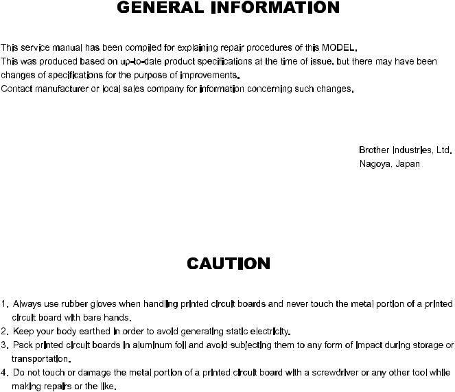
Outline of Mechanism Main Mechanisms
Sewing Machine
Thread guide mechanism
Needle bar / Presser mechanism
Needle threader |
mechanism |
Bobbin winder mechanism
Upper shaft mechanism
Side feed mechanism Feed / Rotary hook mechanism
1 - 2
Outline of Mechanism Driveline
A) Up and down movement of needle bar, movement of thread take-up lever and zigzag mechanism
Thread take-up |
Upper shaft |
Pulley |
|
|
|
|
counter weight |
|
|
|
|||
|
|
|
|
|
||
Needle bar crank |
Thread take-up lever |
|
|
|
|
|
Needle bar crank rod |
|
|
|
|
|
|
Needle bar block |
|
|
|
|
|
|
Needle bar |
Needle bar supporter |
Z zigzag lever |
Z zigzag cam |
Z pulse motor |
||
assy |
||||||
|
|
|
|
|
||
Needle |
|
|
|
|
|
|
|
Needle bar crank |
Upper shaft |
|
|||
Needle bar supporter assy |
|
|
||||
|
|
|
|
|||
Z zigzag cam |
|
Z pulse motor |
|
Z zigzag lever |
Pulley |
|
|
|
Thread take-up counter weight |
Needle bar |
Needle bar crank rod |
|
Needle bar block |
Needle |
|
B) Movement of feed dog and rotary hook
|
|
Timing pulley D |
|
Timing belt |
|
Upper shaft |
|
Upper shaft |
|
Pulley |
|||||||
|
|
|
|
pulley |
|
|
|||||||||||
|
|
|
|
|
|
|
|
|
|
|
|
|
|
|
|||
|
|
|
|
|
|
|
|
|
|
|
|
|
Feed module |
|
|
||
|
|
|
|
|
|
|
|
|
|
|
|
|
|
|
|
|
|
Lower shaft |
|
|
Lower shaft |
|
Feed adjuster |
|
F pulse motor |
|
|
|
|
|
|
|
|||
gear |
|
|
|
|
|
|
|
|
|
|
|
||||||
|
|
|
|
|
|
|
|
|
|
|
|
|
|
|
|
|
|
|
|
|
|
|
|
|
|
|
|
|
|
|
|
|
|
|
|
Outer rotary |
|
|
|
|
Feed arm b |
|
|
Feed arm A |
|
|
|
|
|
|
|
||
hook |
|
|
|
|
|
assy |
|
|
|
|
|
|
|
|
|||
|
|
|
|
|
|
|
|
|
|
|
|
|
|
|
|
||
|
|
|
|
|
|
|
|
|
|
|
|
|
|
|
|
|
|
|
|
|
Vertical lever |
|
|
Vertical |
|
Feed bar |
|
|
Feed dog |
|
|
|
|||
|
|
|
|
adjusting screw |
|
|
|
|
|
|
|
||||||
|
|
|
|
|
|
|
|
|
|
|
|
|
|
|
|
||
Pulley
Upper shaft pulley |
Upper shaft |
Feed dog |
|
||
Vertical adjusting screw |
F pulse motor |
Timing belt |
|
Feed bar |
|||
|
|
||
|
|
Timing pulley D |
|
Feed arm A |
|
Lower shaft |
|
|
|
||
Outer rotary hook |
|
|
|
Lower shaft gear |
Feed arm b assy |
|
|
<![endif]>Mechanism
<![if ! IE]><![endif]>Outline of
1 - 3

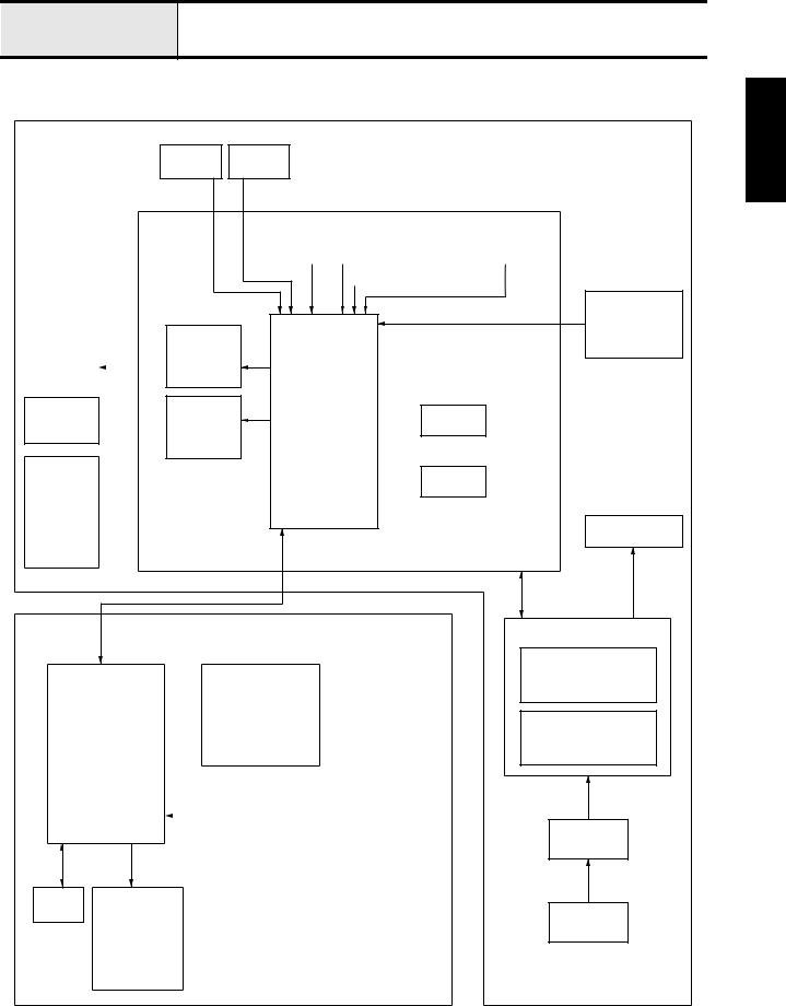
Outline of Mechanism Positions of electronic components
Sewing Machine
SS-VR PCB assy |
LCD PCB assy |
|
|
LED Lamp SR assy |
|
Power PC assy
Power switch/Inlet assy
|
BWSW-S assy |
Z pulse motor |
PFSW-S assy |
BH change switch assy |
NP sensor |
|
|
BH switch lever |
Main PCB assy |
|
|
LED Lamp SL assy |
|
F pulse motor
1 - 4
Outline of Mechanism Control system block diagram
CPS33 S34
PFSW BHSW
MAIN PCB
BWSW |
|
NP |
|
NP |
|
SP |
||
|
SENSOR 2 |
|
SENSOR 1 |
|
SENSOR |
|||
|
|
|
|
|||||
|
|
|
|
|
|
|
|
|
|
|
|
|
|
|
|
|
|
CPU
|
|
ZPM |
ZPM |
|
DRIVER |
|
||
|
|
|
FPM  FPM
FPM
DRIVER
LED PCB
LIGHT
WHITE COLOR
LED (LEFT) 
FRONT
COVER
OPERATION PCB |
BK PCB |
||||
|
|
|
|
|
|
|
Z KEY X2 |
|
|
BK SW |
|
|
|
|
|
||
|
|
|
|
|
|
|
|
|
|
|
|
|
|
|
|
|
|
|
F KEY X2 |
|
|
|
|
|
|
|
|
|
|
|
|
|
|
|
|
|
PATTERN |
|
|
|
|
|
SELECTION X4 |
|
|
|
|
|
|
|
|
||
|
|
|
|
|
|
LCD
LED PCB
LIGHT
WHITE COLOR
LED (RIGHT)
FOOT
CONTROLLER
JACK

 EEPROM
 RESET IC
MAIN MOTOR
POWER SUPPLY PCB
SWITCHING POWER 30V / 5V CIRCUIT
MAIN MOTOR
DRIVE CIRCUIT
POWER
SWITCH
INLET
<![endif]>Mechanism
<![if ! IE]><![endif]>Outline of
1 - 5
Outline of Mechanism Control system block diagram
CPS36 S37
PFSW BHSW
MAIN PCB
BWSW |
|
NP |
|
NP |
|
SP |
||
|
SENSOR 2 |
|
SENSOR 1 |
|
SENSOR |
|||
|
|
|
|
|||||
|
|
|
|
|
|
|
|
|
|
|
|
|
|
|
|
|
|
|
|
ZPM |
|
|
|
ZPM |
|
DRIVER |
|
||
|
|
|
FPM  FPM DRIVER
LED PCB
LIGHT
WHITE COLOR
LED (LEFT) 
FRONT
COVER
OPERATION PCB
Z KEY X2
F KEY X2
PATTERN
SELECTION X4
LCD
LED PCB
LIGHT
WHITE COLOR
LED (RIGHT)
CPU
BUZZER

 EEPROM
 RESET IC
SSVR PCB
SS SW
BK SW
NP SW
SPEED VR
FOOT
CONTROLLER
JACK
MAIN MOTOR
POWER SUPPLY PCB
SWITCHING POWER 30V / 5V CIRCUIT
MAIN MOTOR
DRIVE CIRCUIT
POWER
SWITCH
INLET
1 - 6

Outline of Mechanism Operation of other electronic components
Start/Stop (SS) Switch . . . . . . . . . . . . . . . . . . . . . . Switch for starting and stopping the sewing machine. The machine operates at a slow speed while the switch is being held down.
Reverse switch . . . . . . . . . . . . . . . . . . . . . . . This switch is for backtracking or ending a seam. If the switch is pushed, it makes three to four stitches in that place and stops automatically. If the switch is held down, it sews at a slow speed in the reverse direction as long as the switch is held.
Raise needle switch . . . . . . . . . . . . . . . . . . . . This switch toggles the needle between the up and down positions.
Operation PCB assembly . . . . . . . . . . . . . . . . Input for pattern selection and other conditions necessary for sewing.
BH (buttonhole) switch . . . . . . . . . . . . . . . . This switch is for detecting the forward and rear ends of the buttonhole according to the BH presser and lever.
BH (button hole) lever switch. . . . . . . . . . . . . . This switch detects whether the BH lever is up or down.
NP sensor . . . . . . . . . . . . . . . . . . . . . . . . . . . This sensor detects the drive timing for the pulse motor for zigzagging and feed, the vertical stop position for the needle. It detects the upper shaft angle of rotation using a shutter attached to the upper shaft and an optical sensor.
Speed sensor. . . . . . . . . . . . . . . . . . . . . . . . . This sensor detects the rotational speed of the main motor. It detects the upper shaft rotational speed using a shutter attached to the upper shaft and an optical sensor.
Presser switch. . . . . . . . . . . . . . . . . . . . . . . . This switch detects the vertical position of the presser foot lifter.
BW (bobbin winder) switch . . . . . . . . . . . . . When the bobbin thread is wound, this switch detects whether the bobbin is set for winding or not.
Foot control jack. . . . . . . . . . . . . . . . . . . . . . . This is the jack for plugging in the foot controller when it is used.
LED lamp SR assy., SL assy. . . . . . . . . . . . . White LED lamps for illuminating the work space.
<![endif]>Mechanism
<![if ! IE]><![endif]>Outline of
1 - 7
1 - 8

2 Disassembly
Main parts........................................ |
2 - 2 |
Feed unit........................................ |
2 - 19 |
Needle-presser unit ....................... |
2 - 27 |
 With the CD-ROM version, click
  to start the movie clip.
2 - 1

Main unit
Main parts location diagram
2 - 2 |

Main unit |
Main parts |
|
|
|
|
|
|
|
1Accessory table removal
1.Remove the accessory table 1.
1
2 Bottom cover removal |
2 |
1 |
1.Remove the screw 1, and then remove the base cover 1.
2.Remove the screw 2, and then remove base cover A 2.
1 1
<![endif]>Disassembly
2 - 3
Main unit |
Main parts |
|
|
|
|
|
|
|
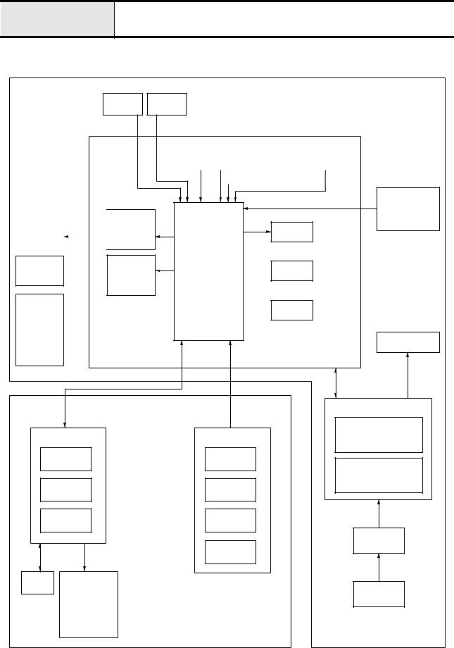
3 Needle plate B assembly removal |
1 |
|
1. |
Remove the needle plate cover 1. |
|
2. |
Remove the needle plate B assembly 2. |
|
2
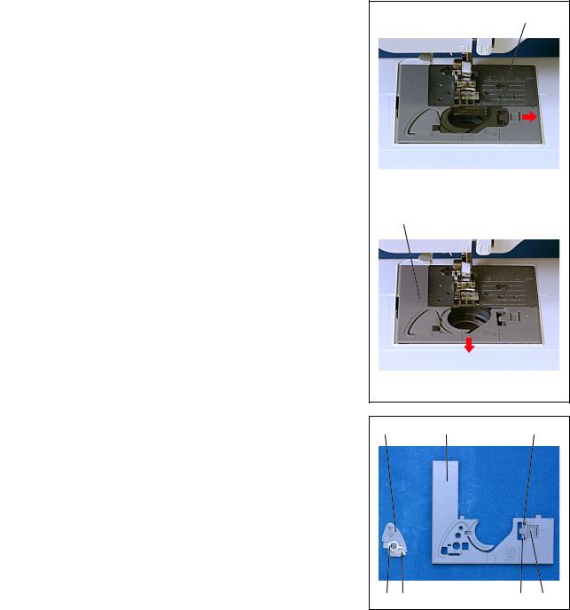
3-1 Needle plate B ASSY disassembly
1.Remove the cutter cover 2 from the needle plate B assembly 1.
2.Remove the spring plate 3 from the cutter cover 2, and then remove the NT lower thread cutter 4.
3.Remove the 2 slide button hooks 5, and then remove the slide button 6.
2 |
1 |
5 |
3 4 |
5 |
6 |
2 - 4
Main unit |
Main parts |
|
|
|
|
|
|
|
|
|
|
4 Face plate assembly removal |
1 |
||
1. Remove the screw 1, and then remove the face plate assembly 1. |
|
|
|
<![endif]>Disassembly
4-1 Face plate A ASSY disassembly
1.Remove the screw 1, and then remove the cutter cover assembly 1.
2.Remove the CS retaining ring 2, and then remove the NT lower thread cutter 3.
1
1
2
3 |
1 |
2 - 5

Main unit |
Main parts |
|
|
|
|
|
|
|
5 Front cover removal |
1 |
1.Remove screws 1 (front, 1 pc.), 2 (rear, 1 pc.), and 3 (rear, 5 pcs.), and then remove the front cover.
*Key point
•Disconnect the SSVR PCB lead wire connector 1 and the operation PCB lead wire connector 2 from the main PCB assembly 3 located near the front cover.
3 2
3
2 |
1 |
3 |
2 - 6

Main unit |
Main parts |
|
|
|
|
|
|
|
6Thread tension holder assembly and thread take-up holder B removal
1.Remove the two screws 1.
2.Remove the thread guide A assembly 1.
3.Remove the screw 2.
4.Remove the thread guide B assembly 2.
6-1 Thread tension holder ASSY disassembly
1.Remove the screw 1, and then remove the notch spring 2 from the thread tension holder assembly 1.
2.Remove the thread dial shaft 3.
*Key point
•Turn the dial clockwise until it stops.
3.Remove the thread tension dial 4 and the thread tension plate assembly
5.
4.Remove the spring 6, washer 7, tension disc washer 8, thread release plate 9, washer 7, tension disc B ;, and then tension disc A A in this order from the caulking shaft of the thread tension holder assembly 1.
5.Remove the thread tension adjusting screw B from the thread tension plate assembly 5.
|
1 |
|
|
1 |
2 |
2 |
<![if ! IE]> <![endif]>Disassembly |
|
|
|
|
9 |
5 |
|
|
|
|
|
|
|
6 |
|
|
0 |
8 |
|
|
|
|
|
|
|
|
B |
|
A |
7 |
|
|
|
1 |
2 |
|
|
|
|
|
|
|
1 |
|
|
4 |
|
|
|
3 |
|
|
2 - 7
Main unit |
Main parts |
|
|
|
|
|
|
6-2 Thread take-up holder B disassembly |
|
|
|
|
|
||
1. Remove the screw 1. |
1 |
1 |
|
|
|
|
|
2.Remove the thread catching spring case 2 from thread take-up holder B
1.
3.Remove the thread take-up spring 3 from the thread catching spring case
2.
4.Remove the thread guide wire 4 from thread take-up holder B 1.
2
3 |
2 |
4
1
7 LED lamp removal |
1 |
2 |
1.Disconnect the LED lamp connector 2 from the operation PCB 1.
2.Remove the screw 1, and then remove the LED lamp 3.
1 3
2 - 8
Main unit |
Main parts |
|
|
|
|
|
|
|
8Operation PCB assembly and SSVR PCB assembly removal
1.Remove the 2 screws 1, and then remove the operation PCB assembly 1.
2.Disconnect the LCD cable 2 from the operation PCB assembly 1.
3.Remove the 3 screws 2, and then remove the SSVR PCB assembly 3.
*Key point
•Remove the bands (2 locations) securing the cords of the operation PCB assembly 1 and the SSVR PCB assembly 3.
9Button removal
1.Remove the 2 selecting buttons 1.
2.Remove manual button A 2 and manual button B 3.
3.Remove the SS button 4, the backstitching button 5, and the NP button
6.
10Front panel and LCD removal
1.Remove the 2 screws 1.
2.Remove the front panel 1 and the LCD 2.
1 |
1 |
2 |
1 |
2 3 2
2 3 1
6 5 4
1
1
2
<![endif]>Disassembly
2 - 9

Main unit |
Main parts |
|
|
|
|
|
|
|
11SV keytop removal
1.Remove the SV keytop 1.
*Key point
•Press the SV keytop hooks (2 locations) from the inside of the front cover to remove the SV keytop.
1
12Base plate rubber removal
1.Remove the 2 base plate rubbers 1.
|
|
1 |
|
|
|
|
|
|
13 Upper cover thread guide removal |
|
1 |
1. Remove the upper cover thread guide 1. |
|
|
|
|
|
2 - 10
Main unit |
Main parts |
|
|
|
|
|
|
|
|
|
|
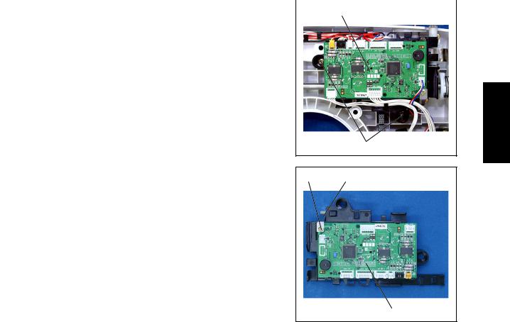
14 Main PCB assembly removal |
1 |
||
1.Remove the 2 screws 1.
2.Remove the main PCB assembly 1.
1
14-1 Main PCB ASSY disassembly
1 1
1.Remove the screw 1.
2.Remove the main PCB plate spring 1, and then remove the main PCB 2.
2
<![endif]>Disassembly
2 - 11
Main unit |
Main parts |
|
|
|
|
|
|
|
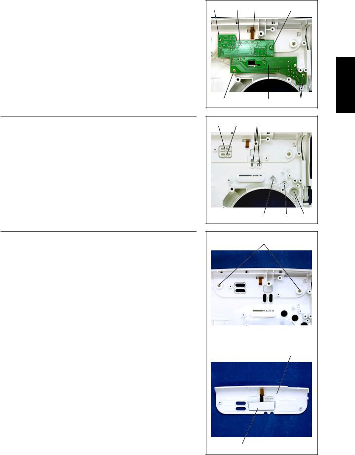
15Power PCB assembly removal
1.Remove screws 1 and 2 (2 pcs. /1pc.), and then remove the power PCB assembly 1.
2.Disconnect the main motor lead wire 2 and the inlet assembly connector
3.
*Key point
•Hold the hook on the inlet assembly connector 3 and pull it out.
15-1 Power PCB ASSY disassembly
1.Disconnect the power lead wire assembly connector 1.
2.Remove the screw 1, and then remove the power plate spring 2.
3.Remove the screw 2, and then remove the insulator sheet 3.
4.Remove the power PCB 4.
16Inlet assembly removal
1.Remove the screw 1, and then remove the inlet assembly 1.
1 2 2
1
3
2 |
1 |
1 |
4 |
23
1 1
2 - 12

Main unit |
Main parts |
|
|
|
|
|
|
|
17FC jack removal
1.Remove the jack nut 1, and then remove the FC jack assembly 2.
|
1 |
|
2 |
||
|
|
|
|
|
|
|
|
|
|
|
|
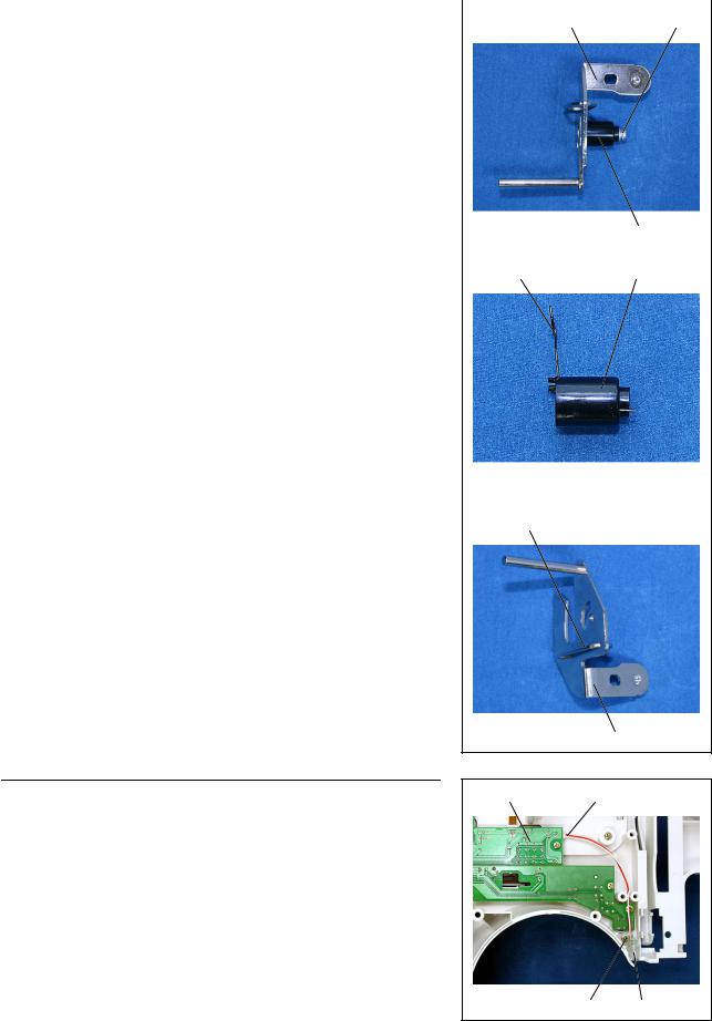
18 Main motor assembly removal |
|
1 |
2 |
||
1. |
Remove the 2 screws 1, and then remove the main motor assembly 1. |
|
|
||
2. |
Remove the motor belt 2 from the main motor assembly 1. |
|
|
||
1
18-1 Main motor ASSY disassembly |
1 |
||
1. |
Remove the motor fan 1. |
||
2 |
|||
2. |
Remove the 2 screws 1, and then remove the main motor 3 from the |
||
|
|||
|
motor holder 2. |
|
|
1
3
<![endif]>Disassembly
2 - 13

Main unit |
Main parts |
|
|
|
|
|
|
|
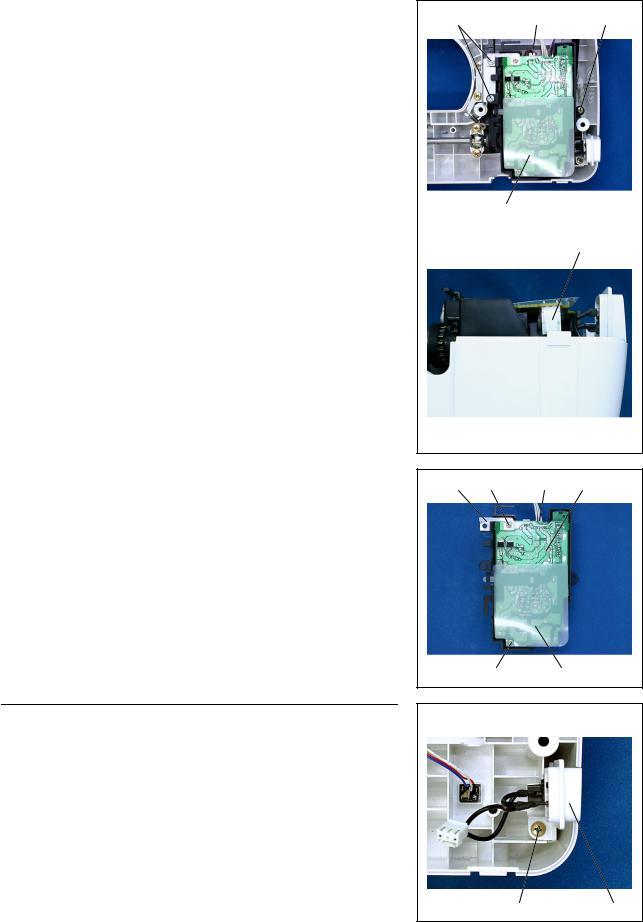
19 Tension pulley assembly removal |
1 |
1 |
1.Remove spring S09 .
2.Remove the 2 screws 1, and then remove the tension pulley assembly 1.
S09
19-1 Tension pulley ASSY disassembly |
|
1. Remove the screw 1, and then remove the tension pulley holder 2 from |
|
the tension pulley assembly 1. |
1 |
2
|
|
1 |
|
|
|
|
|
|
20 Feed unit assembly removal |
|
1 |
1.Remove the 2 screws 1, and then remove the upper shaft bearing presser
1.
2.Remove the 2 screws 2, and then remove the feed unit assembly 2.
1
2
2
2 - 14
Loading...