


BAS-411
SERVICE
MANUAL
FOR
BAS
-4
11
BAS -415
SINGLE HEAD ELECT RONIC EMBROIDERY
MACHINE
I
· ·
.
~
-
From the library of: Superior Sewing Machine & Supply LLC
CONTENTS
(
PART
NAMES )
·.
· · · · · · · · · · · · · · · · · · · · · · · · · · · · · · · · · · · · · · · · · · · · · · · · · · · · · · · · · · · · · · · · · · · · · · · 1
( MECHANICAL
DESCRIPTIONS ) · · · · · · · · · · · · · · · · · · · · · · · · · · · · · · · · · · · · · · · · · · · · · · · · · · · · · · 3
[I] .upper
shaft
mechanism . . . . . • . . . . . . . . . . . . . . . . . • • . . . . . . . . • . . . . . . . . . . • . . • • . . • . . . . . . . . . . . . 3
00
Lower
shaft
and
rotary
hook
mechanism . . . . . . • • • • • . . . . . . . . . . . . . . . • . . . • • . . • • . . . . . . . • . . . . 4
00
Thread
trimmer
mechanism . • . . . . . . . . . . • . . . . . . . . . . . . . . . . . . . . . . . . . . . . . . . . • . . . . . . • • • • • • . • 5
[j]
Thread
wiper
mechanism . • . . • . . . . . . . . . . . . . . • . • . . . . . . . . . . . . . . . . . . . • • • • • . • • . • . . . . . . . • . . . 6
[§] Needle
bar
flip-up
mechanism . . • • . . . . . . . . . . . . . . . . . . . . . . . . . . . . . . . . . . . . • . . . . . . . . . . • • • . • • . 7
[§] Picker mechanism • . . . . . . . . . . . . . . . . . . . . . . . . . . . • . • • . . . . . . . • . . . . . . . • . • . . • • . • . . . . . . • . . . . . . 8
[1]
Drive, (X)
feed
mechanism . . . . . . . . . . . . . . . . . . . . . . . . . . . . . . . . • • • . . . . • . . . • . . . . . . . . . . . . . . . • . 9
[I]
Drive, (Y)
feed
mechanism . . . . . . . . . . . . . . . . . . . . • . • . . . . . . . . . . . . . . . . • . • . . • . . . . . . . . . . . . • • . 10
( STANDARD ADJUSTMENT ) · · · · · · · · · · · · · · · · · · · · ·
·.
· · · · · · · · · · · · · · · · · · · · · · · · · · · · · · · · · · ·
11
[I]
Adjusting
needle
bar
height
...•..............••......
~
. . . . . . . . . • • . . . . . . . . • . . • • • • • • • • •
11
~
Adjusting
timing
of
needle and
rotary
hook
. . • . . . • • . . . . . . . . . . . . . . . . . . . . . . . . . . . . • . • • • • . • 13
00
Adjusting
cloth
presser
height
. . . . . . . . . . . . . . . . . . . . . . . . . . . . . . . . . . . . • . • . . . . . . . . . . . . . . . . • . 13
[j]
Adjusting
knife
and
fixed
knife
. • . . . . . . . . . . . . . • • . . . . . . . . . . . . . . . . . • . . . . . . . . . . . . . . . . . . . . . 14
[§]
Adjusting
picker . . . . . . . . . . . . . . . . . . . . . . . • . . . . . . . . . . . . . . . . . . . • . . . . . . . . . . . . . . . . . . . • • • • . . 15
[§]
Adjusting
the
thread
wiper
. . . . . . . . . . . . . . . . . . . . . . . . . . . . . . • . . . . . . . . • . . . . . . . . . • . . . . . . . • • 16
[1]
Adjusting
wire
tension
.....•.................•........................••...•.•...••••
17
1.
X-
feed
wire
. . . . . . . . . . . . . . . . . . . . . . . . . . . . . • . . . . . . . . . . • . . . . . . • . . . . . . . . . . . . . • . • • • • • . 17
2.
Y
-feed
wire
. . . . . . . . . . . . . . • . . . . . . . . • . . . . . . . . . . . . . . . . . . . . . . . . . . . . • . . . . . . . . . . . • . . . . 18
00
Adjusting
thread
breakage
detect
stud
..........................•.•.....•.•............
19
00
Adjusting
bobbin
winder
...................•.........................................
20
lim
BAS-411·415
test
mode
. . . . . . . . . . . . . . . . . . . . . . . . . . . . . . . . . . . . . . . . . . . • • • • • • . . . . • . . . . . . . . .
21
In]
Adjusting
synchronizer . . . . . . . • . • . . . . . . . . . . . . . . . . . . . . . . . . . . . . . . . . . . . . . . . . . . . . . . . • . . . . . 23
1m
Adjusting
home
position
using
home
position
plate
. . . . . . . . . . . . . . . . • . . . • . . . . . . . . . • . . . . . . 26
lj}
Positioning
over
limit
sensor
...................................•..••..•...............
28
IB1
How
to
adjust
thread
sensor (thread breakage detector) . . . . . . . . . . . . . . . . . . . . . . . . . . • . . . . . . 35
( LUBRICATION ) · · · · · · · · · · · · · · · · · · · · · · · · · · · · · · · · · · · · · · · · · · · · · · · · · · · · · · · · · · · · · · · · · · · · · · · 36
[I]
Machine
head . . . . . . . . . . . . . . . . . . . . . . . . • . . . • . . . . . . . . . . . . . . . . . . . . . . • • • • • . . • . . . . . . . . . . . . 36
~
Feed
guide
mechanism
.......................................•........•..............
38
From the library of: Superior Sewing Machine & Supply LLC
(
REPLACINGANDADJUSTINGPARTS)
· · · ·
··
· · · · · · · · · · · · ·
··
· · · ·
··
· · · · · · · ·
··
· · · · · · ·
··
39
[I]
Removing and
adjusting
machine head (1) . . . . . . . . . . . . . . . . . . . . . . . . . . . . . . . . . . . . . . . . . . . . . 39
~
Removing and
adjusting
machine head (2) .
..
. . . . .
..
.
..
..
. . . . . . .
..
. . . . .
.. ..
..
.. .. ..
. . . . 40
lm
Removing needle
bar
case
............................................................
41
1!1
Replacing
up
and
down
motion
parts . . . . . . . . . . . . . . . . . . . . . . . . . . . . . . . . . . . . . . . . . . . . . . . . . . 42
~
Replacing
jump
solenoid
..............................................................
43
[§]
Attaching
X
wire
.....................................................................
44
[1]
Attaching
Y
wire
.....................................................................
45
(
ELECTRIC
COMPONENTS ) · · · · · · · · · · · · · · · · · · · · · · · · · · · · · · · · · · · · · · · · · · · · · · · · · · · · · · · · · 46
[!)
Circuit
board
locations
...•............................................................
46
~
Replacing
circuit
board
...............................................................
47
00
Fuses
...............................................................................
58
(!]
P-ROMS
. . . . . . . . . . . . . . . . . . . . . . . . . . . . . . . . . . . . . . . . . . . . . . . . . . . . . . . . . . . . . . . . . . . . . . . . . . . . . 60
~
DIP switches . . . . . . . . . . . . . . . . . . . . . . . . . . . . . . . . . . . . . . . . . . . . . . . . . . . . . . . . . . . . . . . . . . . . . . . . . 62
[§]
Connectors . . . . . . . . . . . . . . . . . . . . . . . . . . . . . . . . . . . . . . . . . . . . . . . . . . . . . . . . . . . . . . . . . . . . . . . . . . 67
[1]
troubleshooting
flowchart
...........................................................
70
BAS-411
..........................................................................
70
BAS-415
..........................................................................
81
00
Harness connections and connectors
number
...........................................
92
(
EXPLANATIONOFOPTIONALPARTSINSTALLATION)
· · · · · · · · · · · · · · · · · · · · · · · · · · · 106
[]]
ML
6511amp set . . . . . . . . . . . . . . . . . . . . . . . . . . . . . . . . . . . . . . . . . . . . . . . . . . . . . . . . . . . . . . . . . . . 106
~
Light
marker
. . . . . . . . . . . . . . . . . . . . . . . . . . . . . . . . . . . . . . . . . . . . . . . . . . . . . . . . . . . . . . . . . . . . . . 107
00
Connecting
optional
parts
with
machine . . . . . .
..
..
. . . . . . . . . . . . .
.. ..
. . . .
..
. .
..
. . . . .
..
. 112
1!1
Bobbin
winder
. . . . . . . . . . . . . . . . . . . . . . . . . . . . . . . . . . . . . . . . . . . . . . . . . . . . . . . . . . . . . . . . . . . . . 116
(
TROUBLESHOOTING)·····························································
118
[!) Mechanical
problem
. . . . . . . . . . . . . . . . . . . . . . . . . . . . . . . . . . . . . . . . . . . . . . . . . . . . . . . . . . . . . . . 118
~ Electrical
problem
. . . . . . . . . . . . . . . . . . . . . . . . . . . . . . . . . . . . . . . . . . . . . . . . . . . . . . . . . . . . . . . . . . 120
00
List
of
error
messages . . . . . . . . . . . . . . . . . . . . . . . . . . . . . . . . . . . . . . . . . . . . . . . . . . . . . . . . . . . . . . . 122
BAS-411 . . . . . . . . . . . . . . . . . . . . . . . . . . . . . . . . . . . . . . . . . . . . . . . . . . . . . . . . . . . . . . . . . . . . . . . . 122
BAS-415 . . . . . . . . . . . . . . . . . . . . . . . . . . . . . . . . . . . . . . . . . . . . . . . . . . . . . . . . . . . . . . . . . . . . . . . . 125
BAS-411 KEYBOARD
UN
IT CONTROL
BLOCK
DIAGRAM
BAS-415 KEYBOARD UNIT CONTROL
BLOCK
DIAGRAM
BAS-411 CONTROL
BLOCK
DIAGRAM
BAS-41
5 CONTROL
BLOCK
DIAGRAM
.........................................................
.........................................................
From the library of: Superior Sewing Machine & Supply LLC
(
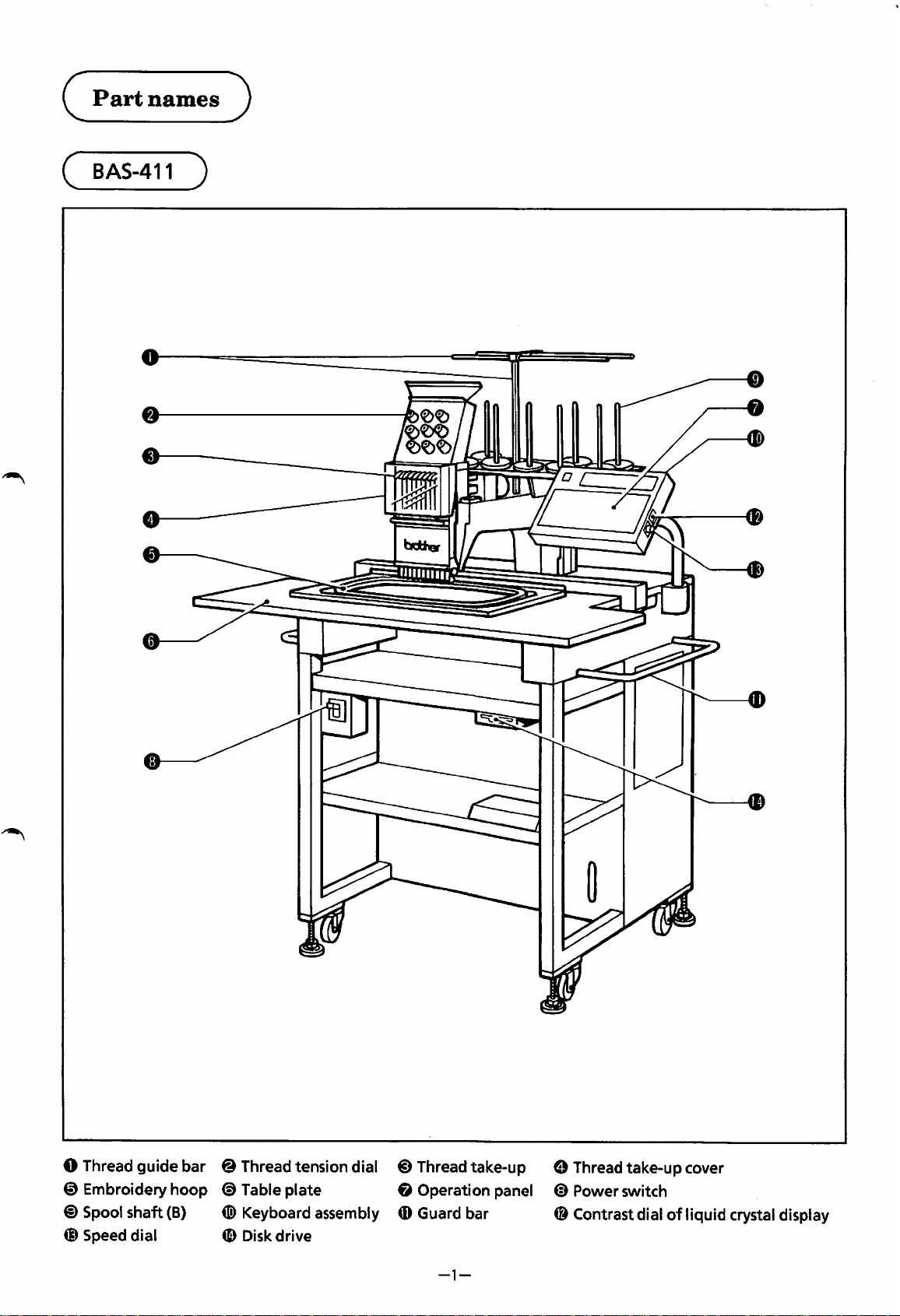
Part
names
)
(
BAS-411
)
0 Thread
guide
bar
@ Thread tension dial
@)
Thread take-up
0 Embroidery
hoop
<9
Table plate 6 Operation panel
@)Spool
shaft
(B)
(!) Keyboard assembly
CD
Guard bar
@ Speed dial
4D
Disk drive
-1-
0 Thread take-up cover
@)
Power switch
48
Contrast dial
of
liquid
crystal display
From the library of: Superior Sewing Machine & Supply LLC
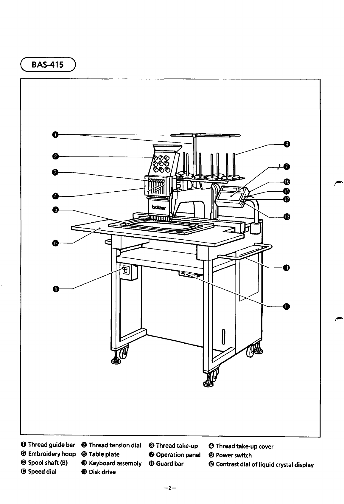
( ·
BAS-415
)
0 Thread
guide
bar 8 Thread tension dial
@)
Thread take-up
@ Embroidery
hoop
(!) Table
plate
8 Operation panel
@)
Spool
shaft
(B)
tD)
Keyboard assembly
4D
Guard bar
Q) Speed dial
4D
Disk drive
-2-
8 Thread take-up cover
~
Power switch
C8
Contrast dial
of
liquid
crystal display
From the library of: Superior Sewing Machine & Supply LLC
(MECHANICAL
DESCRIPTIONS )
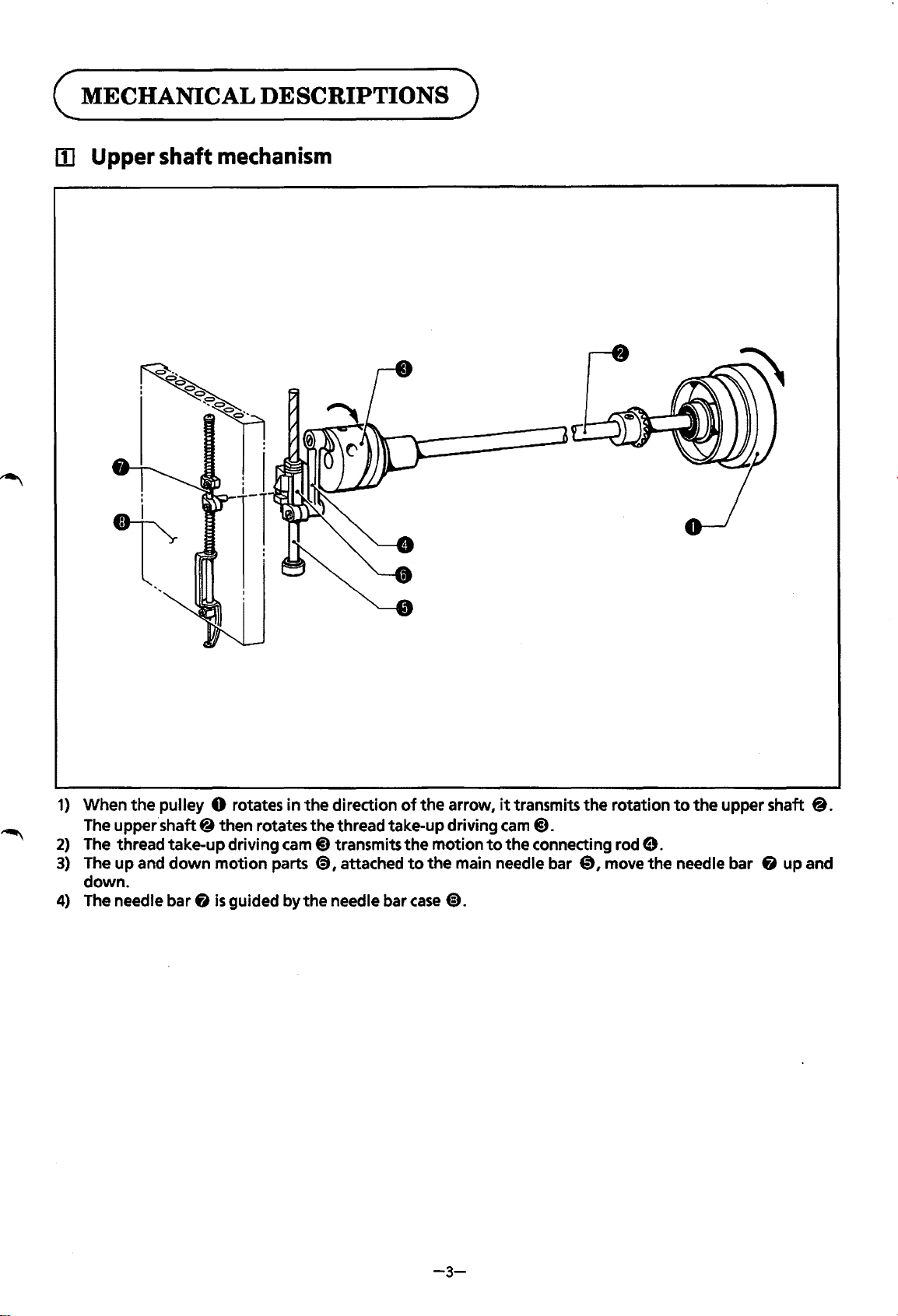
lii Upper shaft
mechanism
1)
When
the
pulley 0 rotates
in
the
direction
of
the
arrow,
it
transmits
the
rotation
to
the
upper shaft
8.
The upper.shaft 8 then rotates
the
thread take-up driving
cam
@).
2)
The thread take-up driving
cam@)
transmits
the
motion
to
the
connecting rod
9.
3)
The
up
and
down
motion
parts
<9,
attached
to
the
main needle bar
0,
move
the
needle bar 8 up and
down.
4)
The needle bar 8
is
guided by
the
needle bar
case
@).
-3-
From the library of: Superior Sewing Machine & Supply LLC
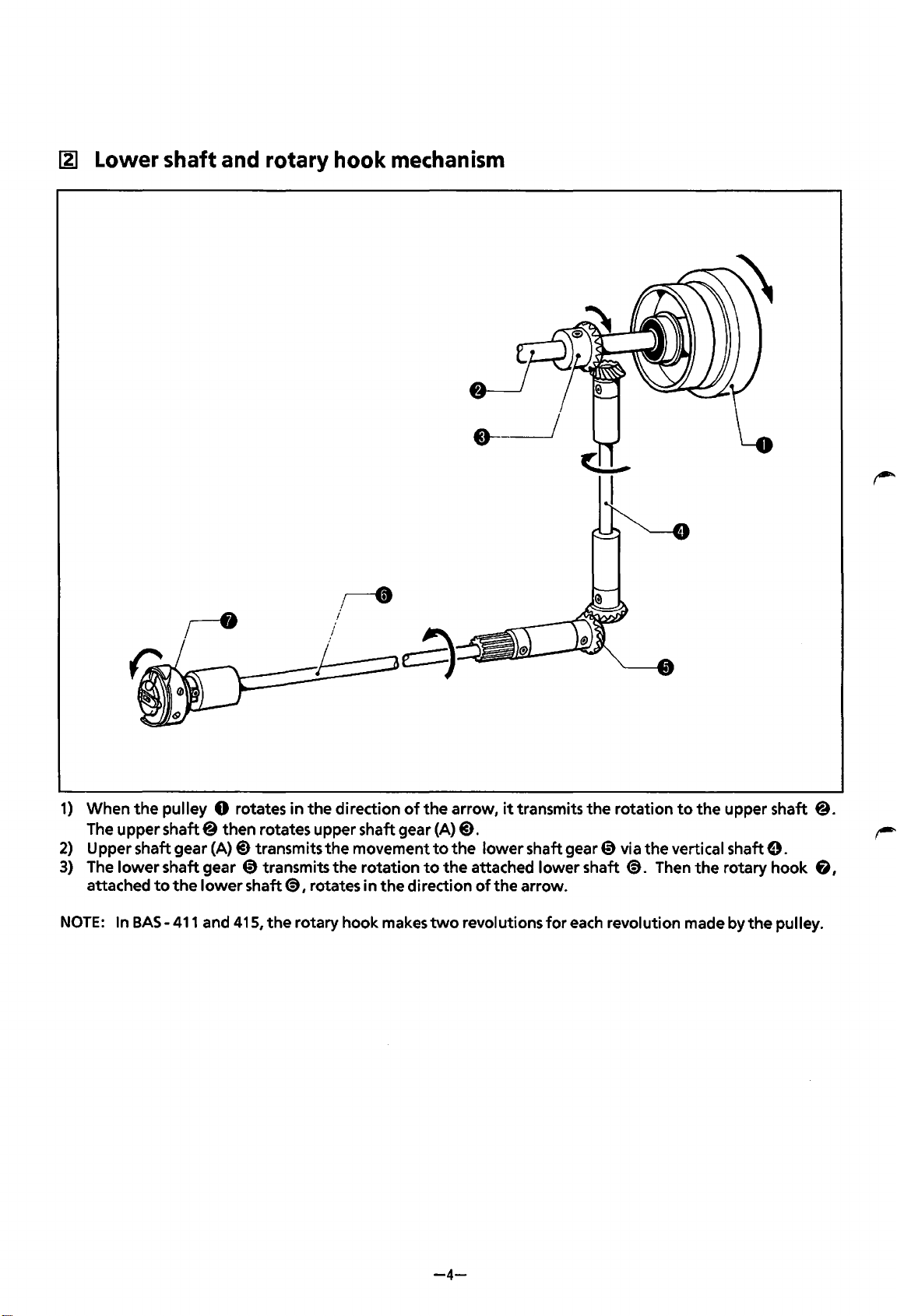
~
Lower shaft and rotary hook mechanism
1)
When
the
pulley 0 rotates
in
the
direction
of
the
arrow,
it
transmits
the
rotation
to
the
upper shaft @.
The upper
shaft@
then rotates upper shaft gear (A)@).
2)
Upper shaft gear
(A)@)
transmits
the
movement
to
the
lower
shaft gear 0 via the vertical shaft
e.
3)
The
lower
shaft gear 0 transmits
the
rotation
to
the
attached lower shaft
@).
Then
the
rotary hook
6,
attached
to
the
lower
shaft@), rotates in
the
direction
of
the arrow.
NOTE:
In BAS-
411
and 415,
the
rotary hook makes
two
revolutions
for
each revolution made by
the
pulley.
-4-
From the library of: Superior Sewing Machine & Supply LLC
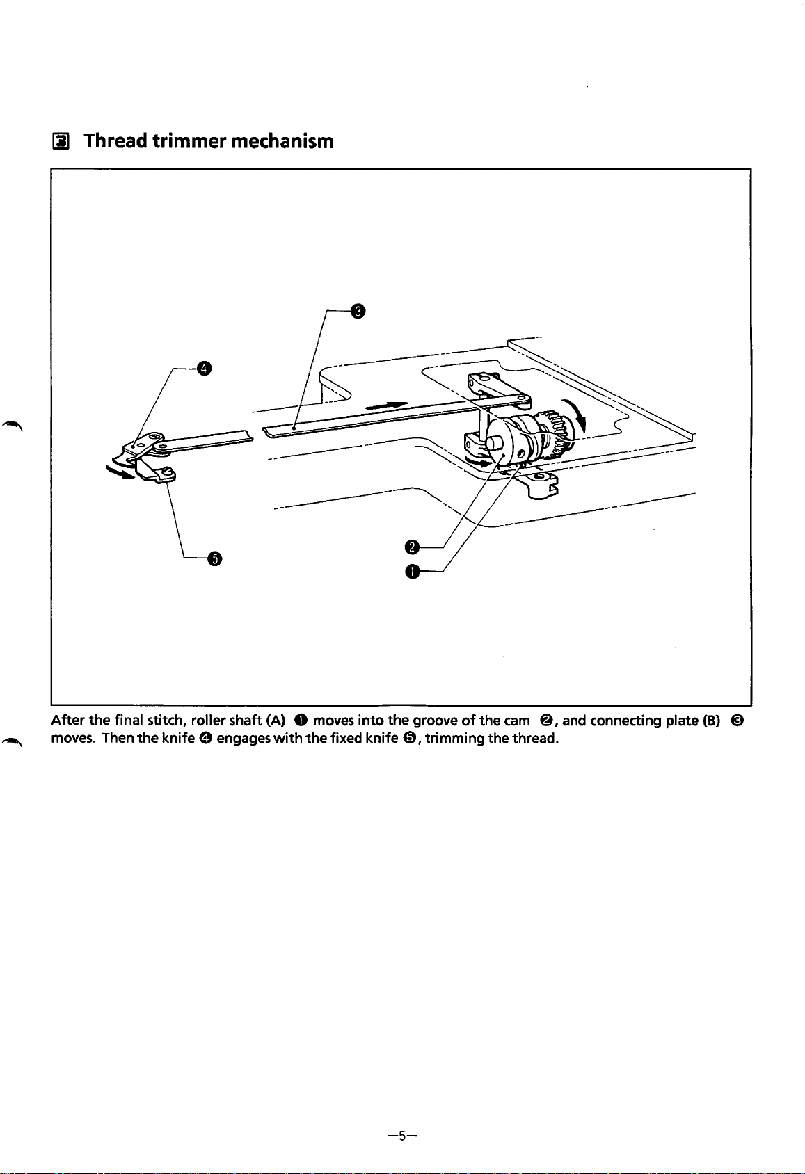
~
Thread trimmer
mechanism
-------------------
After
the
final stitch, roller shaft (A) 0
moves
into
the
groove
of
the
cam
@,and connecting plate
(B)
@)
~
moves.
Then the knife 0 engages
with
the fixed knife
0,
trimming the thread.
-5-
From the library of: Superior Sewing Machine & Supply LLC
II]
Thread
wiper
mechanism
~--------
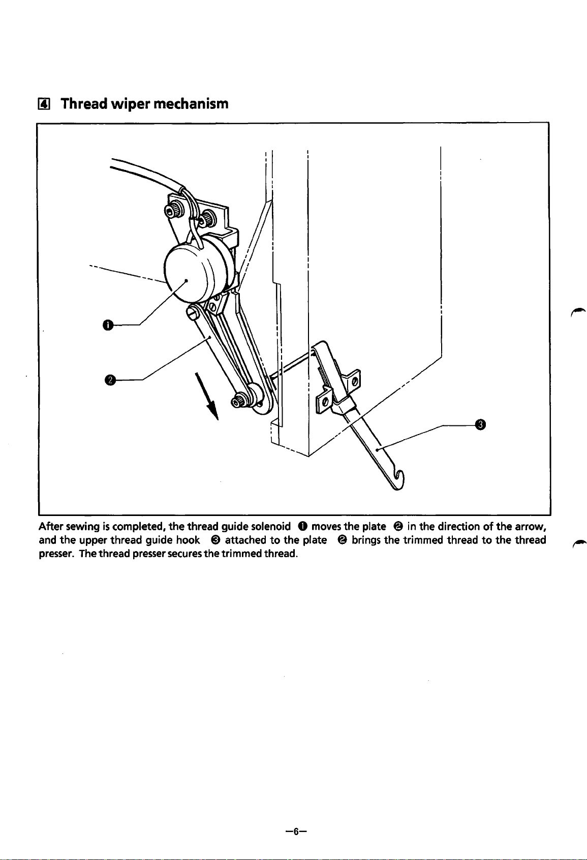
After
sewing
is
completed,
the
thread guide solenoid 0
moves
the
plate
@in
the direction
of
the
arrow,
and
the
upper thread guide hook
@)
attached
to
the plate @ brings the trimmed thread
to
the
thread
presser.
The thread presser
secures
the trimmed thread.
-6-
From the library of: Superior Sewing Machine & Supply LLC
[§]
Needle
bar
flip-up
mechanism
~~------
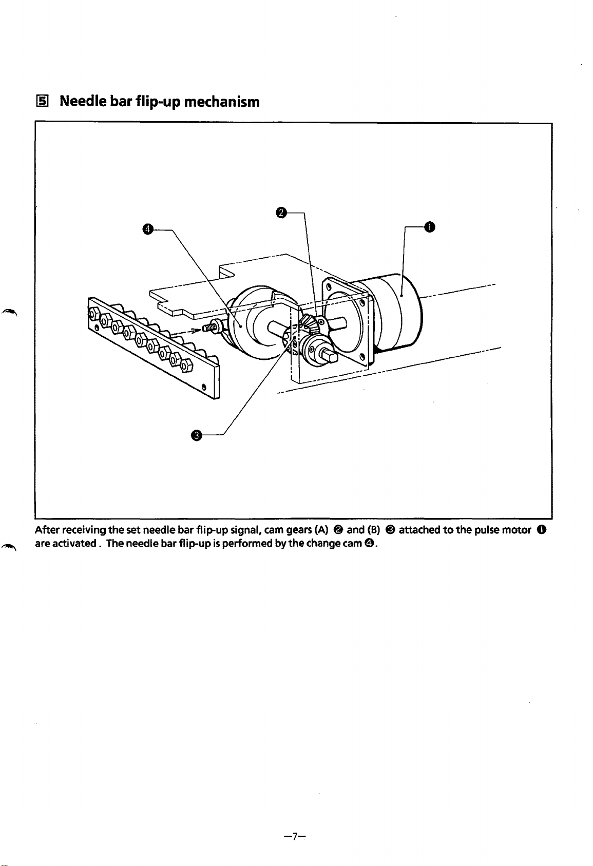
After
receiving
the
set needle bar
flip-up
signal,
cam
gears (A) 8 and
(B)
@)
attached
to
the
pulse
motor
0
are
activated.
The needle bar
flip-up
is
performed
by
the
change cam
9.
-7-
From the library of: Superior Sewing Machine & Supply LLC
[§]
Picker
mechanism
------------
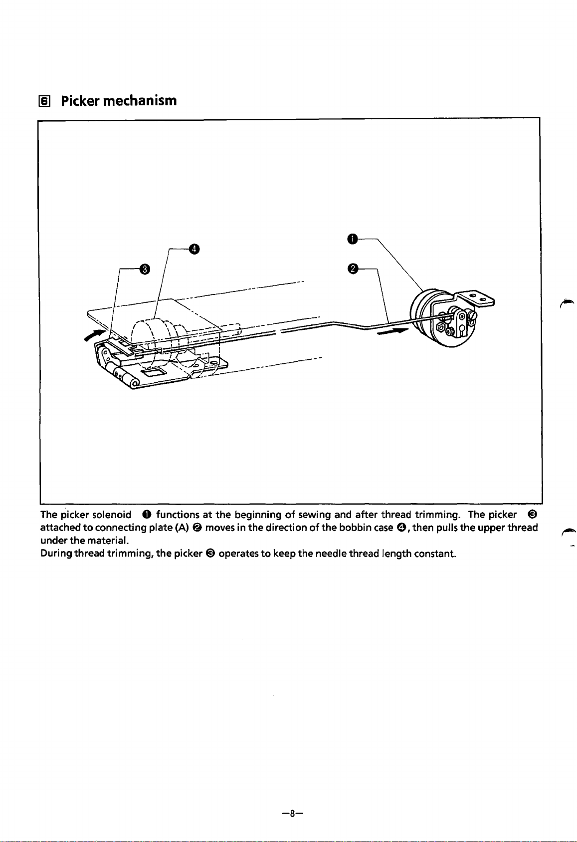
The
picker solenoid 0 functions
at
the
beginning
of
sewing and after thread trimming.
The
picker
@)
attached
to
connecting plate
(A)@
moves in the direction
of
the bobbin
case
e, then pulls the upper thread
under
the
material.
During thread trimming,
the
picker@) operates
to
keep the needle thread length constant.
-8-
From the library of: Superior Sewing Machine & Supply LLC
[1]
Drive, (X) feed mechanism
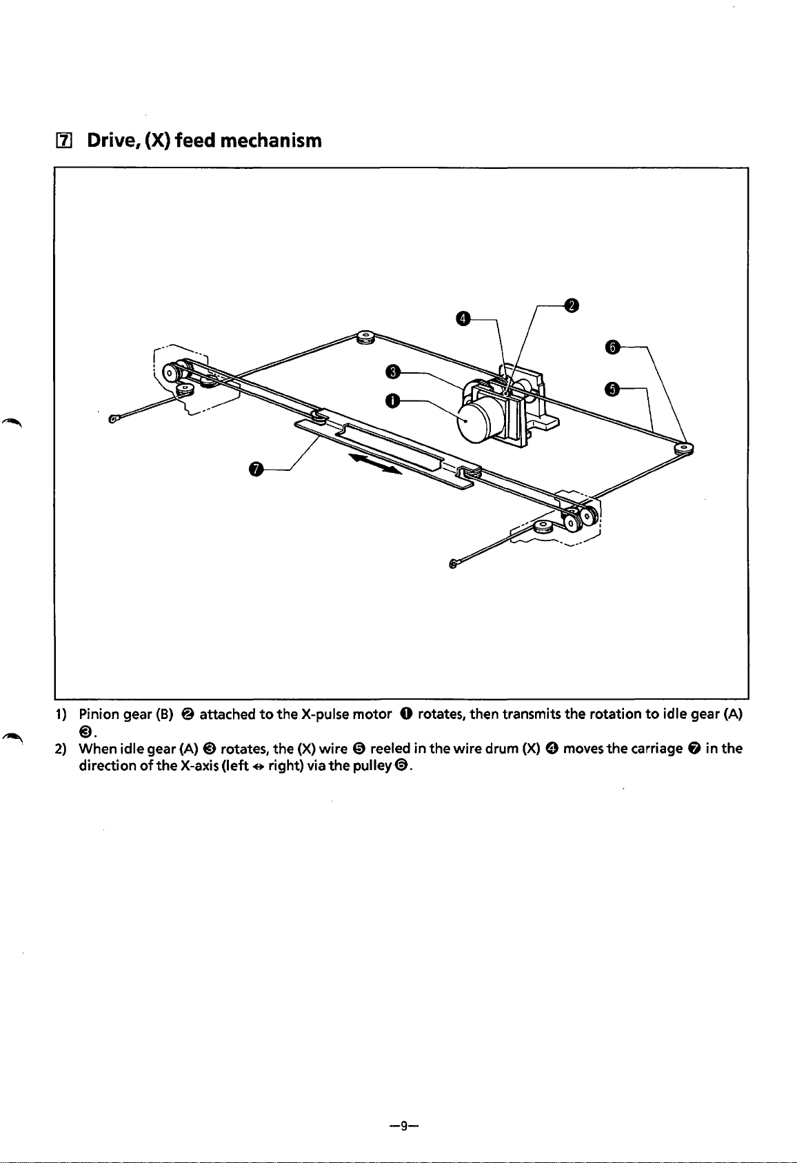
1)
Pinion gear
(B)
@ attached
to
the X-pulse motor 0 rotates, then transmits the rotation
to
idle gear (A)
@).
2)
When idle gear (A)@) rotates, the (X) wire
CD
reeled in the wire drum
(X)
e moves
the
carriage & in
the
direction
of
the
X-axis
(left
e right) via
the
pulley
<9.
-9-
From the library of: Superior Sewing Machine & Supply LLC

[II.
Drive, (Y) feed
mechanism
1)
Pinion gear (B)@
of
theY-pulse motor 0 rotates, then transmits the rotation
to
idle gear
(A)@).
2) When idle gear (A) @)rotates, the
(Y)
wires @)(left) and (right) reeled in
the
wire drums
(Y)
8 on
the
right
and the
left
move the carriage
fi
in the direction
of
theY-axis (backwards e forwards) via the
pulley8.
-10-
From the library of: Superior Sewing Machine & Supply LLC
c
STANDARD
ADJUSTMENT
)
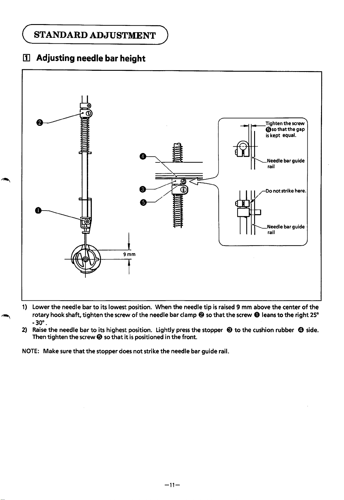
lii
Adjusting
needle
bar
height
Tighten the screw
0so
that
the
gap
is
kept equal.
1)
Lower
the
needle bar
to
its lowest position. When
the
needle
tip
is
raised 9 mm above
the
center
of
the
~
rotary hook shaft,
tighten
the
screw
of
the
needle bar clamp @
so
that
the
screw 0 leans
to
the
right
25°
-30°.
2)
Raise
the
needle bar
to
its highest position. Lightly
press
the
stopper
@)
to
the
cushion rubber 9 side.
Then
tighten
the
screw 0
so
that
it
is
positioned in
the
front.
NOTE:
Make sure
that
the
stopper does
not
strike
the
needle bar guide rail.
-11-
From the library of: Superior Sewing Machine & Supply LLC
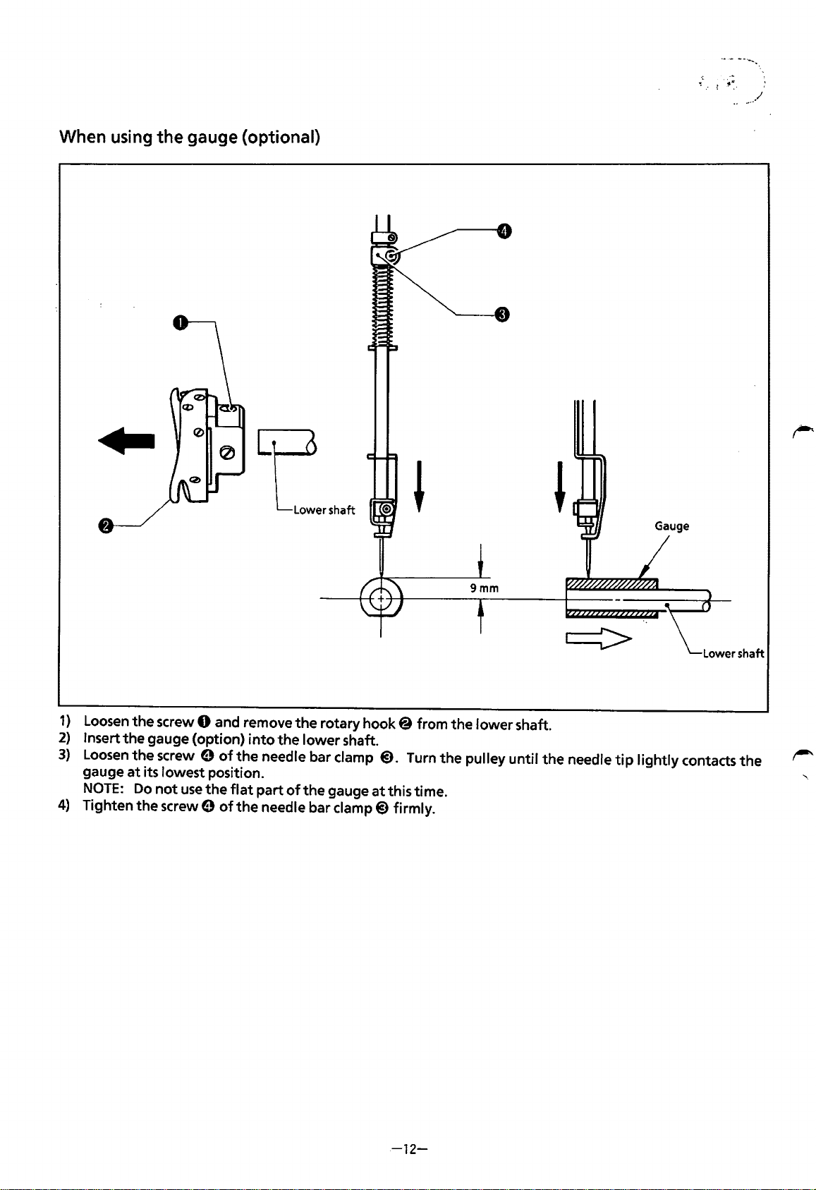
When using
the
gauge (optional)
Gauge
1)
Loosen
the screw 0 and remove
the
rotary
hook@
from the lower shaft.
2)
Insert the gauge (option)
into
the lower shaft.
3)
Loosen
the
screw e
of
the
needle bar clamp
@).
Turn
the
pulley until the needle
tip
lightly contacts
the
gauge
at
its lowest position.
NOTE:
Do
not
use
the
flat
part
of
the
gauge
at
this time.
4)
Tighten
the
screw 9
of
the
needle bar
clamp@)
firmly.
-12-
From the library of: Superior Sewing Machine & Supply LLC
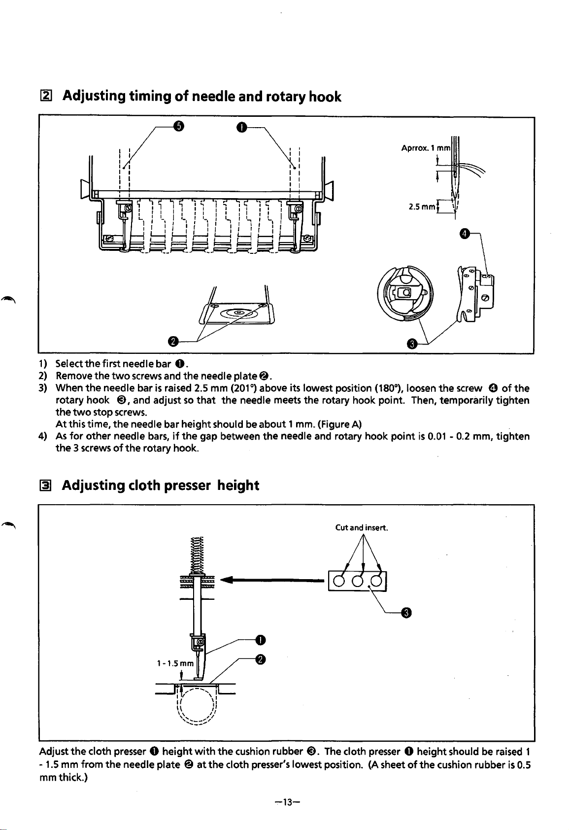
~ Adjusting timing
of
needle and rotary hook
1/
I I
I
I
I
I I
I I
: I
1)
Selectthefirstneedlebar
0.
\
I
I
I
I
I I
I I
I I
2)
Remove
the
two
screws and
the
needle plate@.
Aprrox.1 mm
2.5mm
3)
When
the
needle bar
is
raised
2.5
mm
(201°)
above its lowest position (180°), loosen
the
screw 0
of
the
rotary hook
@),
and adjust
so
that
the
needle meets
the
rotary hook point. Then, temporarily
tighten
the
two
stop screws.
At
this time,
the
needle bar height should be about 1 mm. {Figure A) .
4)
As
for
other needle bars,
if
the
gap between
the
needle and rotary hook
point
is
0.01
-
0.2
mm,
tighten
the
3 screws
of
the
rotary hook.
~
Adjusting cloth presser height
Cut and insert.
Adjust
the
cloth presser 0
height
with
the
cushion rubber
@).
The cloth presser 0 height should be raised 1
-
1.5
mm
from
the
needle plate @
at
the
cloth presser's lowest position. {A sheet
of
the
cushion rubber
is
0.5
mmthick.)
~13-
From the library of: Superior Sewing Machine & Supply LLC
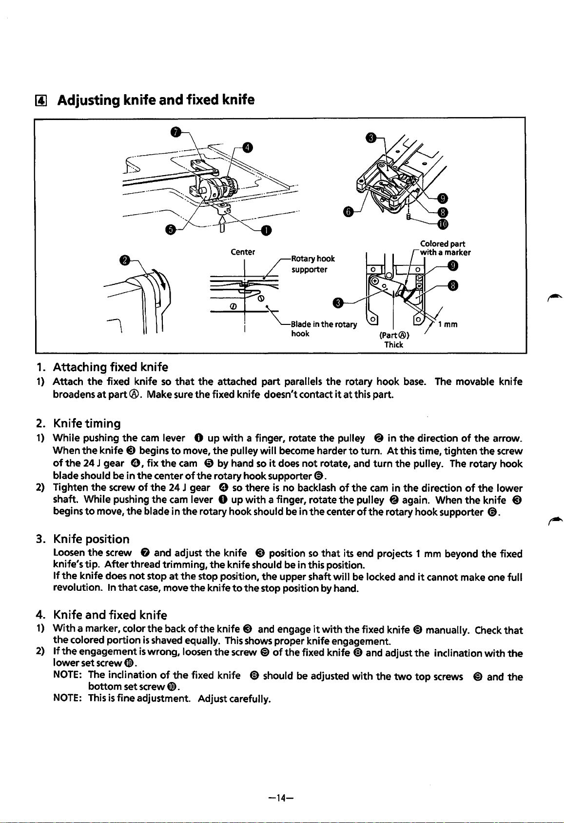
(j] Adjusting knife
and
fixed knife
1.
Attaching fixed knife
1)
Attach
the
fixed knife
so
that
the
attached part parallels
the
rotary hook
base.
The movable knife
broadens
at
part®.
Make sure
the
fixed knife doesn't contact
it
at
this part.
2.
Knife timing
1)
While pushing
the
cam
lever 0 up
with
a finger, rotate
the
pulley @ in
the
direction
of
the
arrow.
When
the
knife
@)
begins
to
move,
the
pulley
will
become harder
to
turn.
At
this time, tighten
the
screw
of
the
24 J gear e I
fix
the
cam
CD
by hand
so
it
does
not
rotate, and
turn
the
pulley.
The
rotary hook
blade should be in
the
center
of
the rotary hook supporter@).
2)
Tighten
the
screw
of
the
24 J gear e
so
there
is
no backlash
of
the
cam
in
the
direction
of
the
lower
shaft. While pushing
the
cam
lever 0 up
with
a finger, rotate
the
pulley @again. When
the
knife
@)
begins
to
move,
the
blade in
the
rotary hook should be in
the
center
of
the
rotary hook supporter
@).
3.
Knife position
Loosen
the
screw & and adjust
the
knife
@)
position
so
that
its end projects 1 mm beyond
the
fixed
knife's tip.
After
thread trimming,
the
knife should be in this position.
If
the
knife does
not
stop
at
the
stop position,
the
upper shaft
will
be locked and
it
cannot make one
full
revolution. In
that
case,
move
the
knife
to
the
stop position by hand.
4.
Knife and fixed knife
1)
With
a marker, color
the
back
of
the
knife
@)
and engage
it
with
the fixed knife
@)
manually.
Check
that
the
colored portion
is
shaved equally.
This
shows proper knife engagement.
2)
If
the
engagement
is
wrong, loosen
the
screw
@)
of
the
fixed knife
@)
and adjust
the
inclination
with
the
lower
set screw
CD).
NOTE:
The inclination
of
the
fixed knife @)should
be
adjusted
with
the
two
top
screws
@)
and
the
bottom set screw
CD).
NOTE:
This
is
fine adjustment. Adjust carefully.
-14-
~-
From the library of: Superior Sewing Machine & Supply LLC
1§1
Adjusting
picker
Figure A
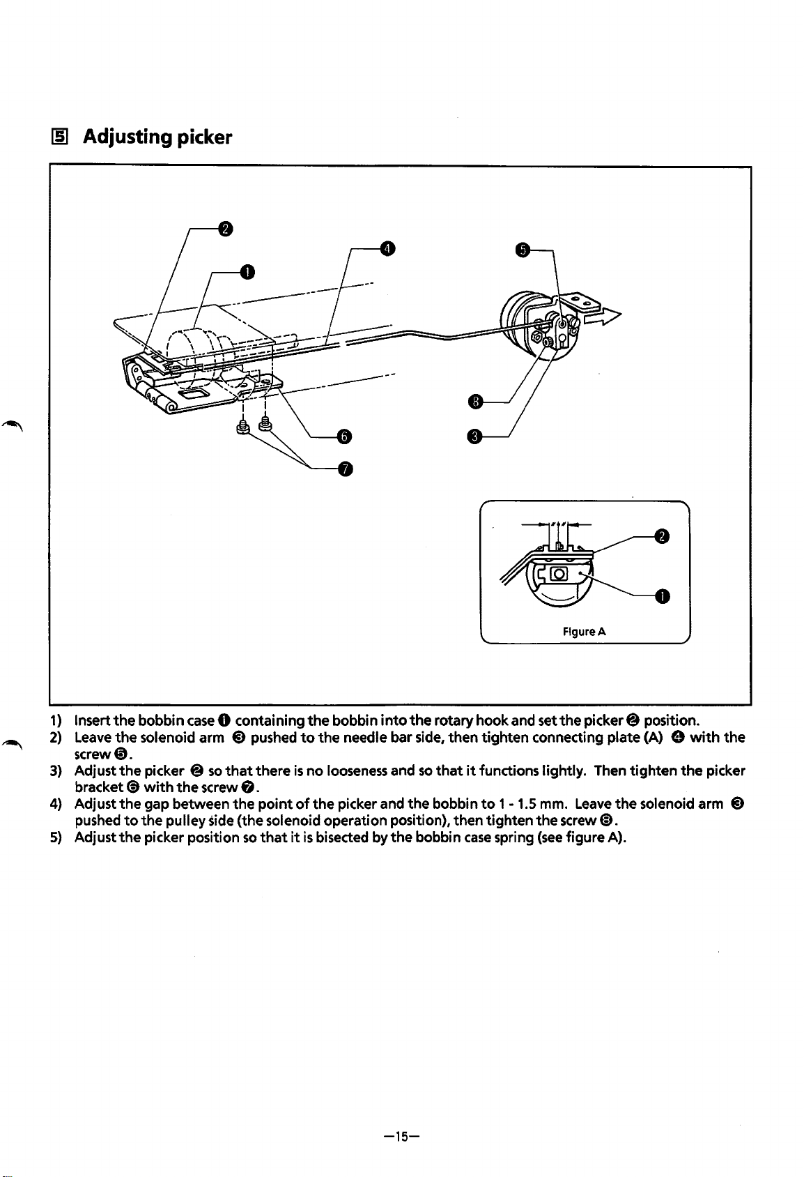
1)
Insert
the
bobbin
case
0 containing
the
bobbin
into
the
rotary hook and set
the
picker@ position.
2)
Leave
the
solenoid arm
@)
pushed
to
the
needle bar side, then
tighten
connecting plate (A) e
with
the
screw0.
3)
Adjust
the
picker @
so
that
there
is
no
looseness and
so
that
it
functions lightly. Then
tighten
the
picker
bracket(!)
with
the
screw
8.
4)
Adjust
the
gap between
the
point
of
the
picker and
the
bobbin
to
1
-1.5
mm.
Leave
the
solenoid arm
@)
pushed
to
the
pulley side (the solenoid operation position), then tighten
the
screw@).
5)
Adjust
the
picker position
so
that
it
is
bisected by
the
bobbin
case
spring
(see
figure A).
-15-
From the library of: Superior Sewing Machine & Supply LLC
[§]
Adjusting
the
thread wiper
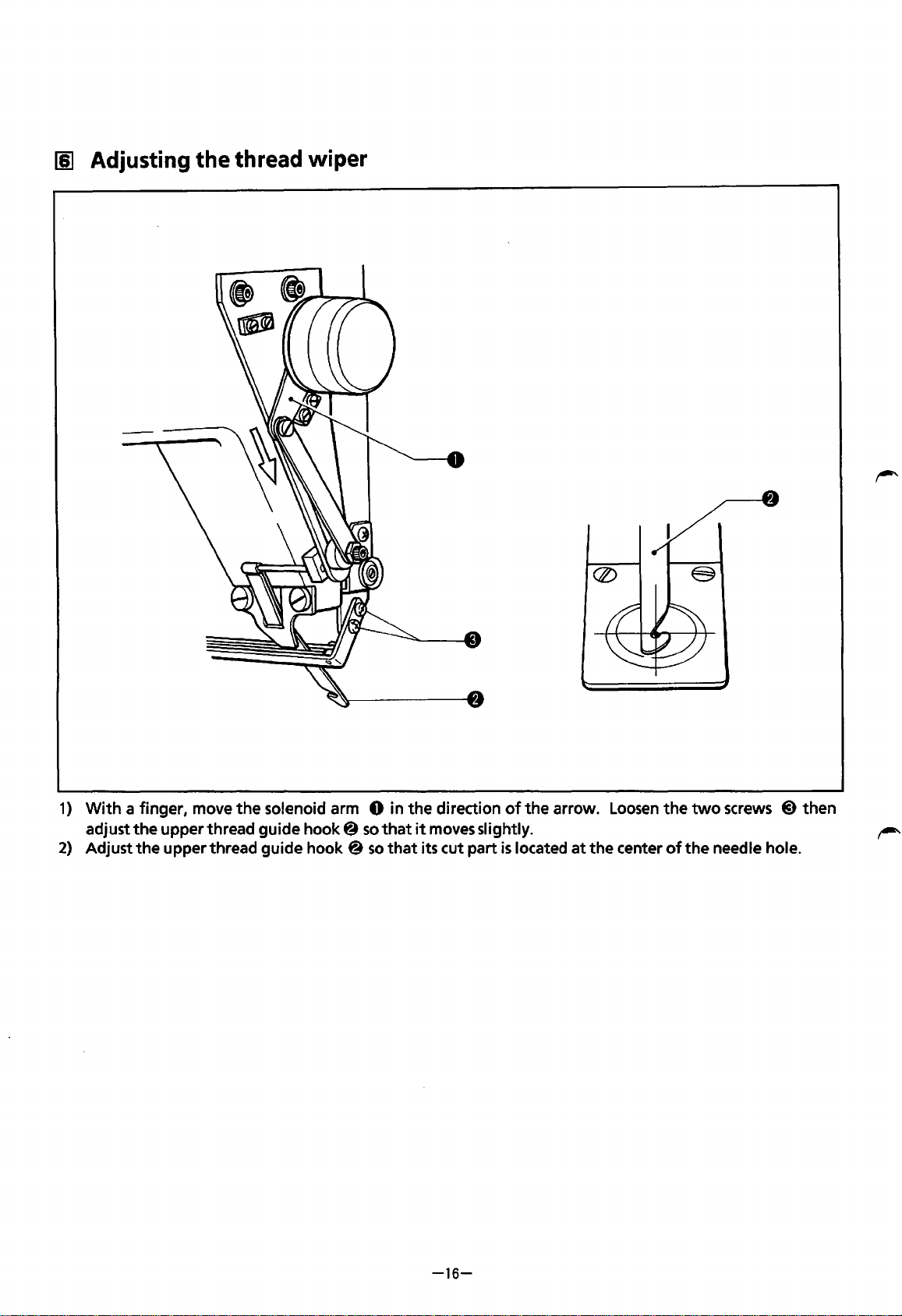
1)
With
a finger, move
the
solenoid arm 0 in
the
direction
of
the
arrow.
Loosen
the
two
screws @ then
adjust
the
upper thread guide
hook@
so
that
it
moves slightly.
2)
Adjust
the
upper thread guide hook @
so
that
its cut part
is
located
at
the
center
of
the
needle hole.
-16-
From the library of: Superior Sewing Machine & Supply LLC
111
Adjusting
wire
tension
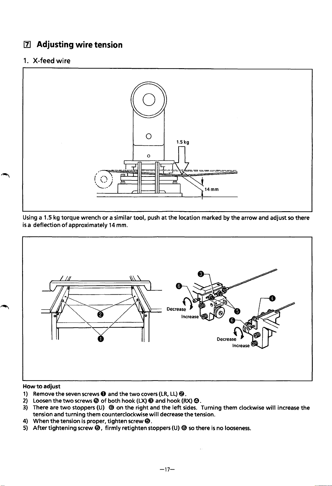
1.
X-feed wire
0
1.5 kg
Using a 1.5 kg
torque
wrench
or
a similar
tool,
push
at
the
location marked by
the
arrow
and adjust
so
there
is
a deflection
of
approximately
14
mm.
How
to
adjust
1)
Remove
the
seven screws 0 and
the
two
covers
(LR,
LL)@.
2)
Loosen
the
two
screws 0
of
both
hook
(LX)
@)
and hook
(RX)
0.
3)
There are
two
stoppers (U)
(S)
on
the
right
and
the
left
sides.
Turning them clockwise
will
increase
the
tension and
turning
them counterclockwise
will
decrease
the
tension.
4) When
the
tension
is
proper,
tighten
screw
0.
5)
After
tightening
screw
0,
firmly
retighten stoppers
(U)
(S)
so
there
is
no
looseness.
-17-
From the library of: Superior Sewing Machine & Supply LLC
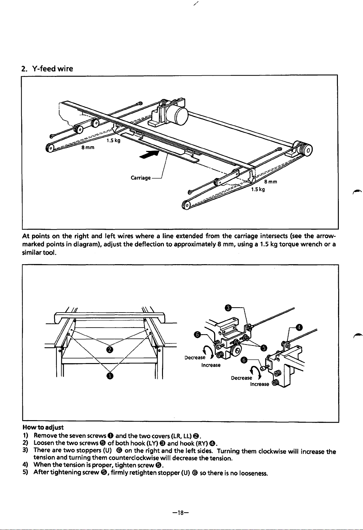
2.
Y-feed wire
At
points
on
the
right
and
left
wires where a line extended from
the
carriage intersects
(see
the
arrow-
marked points
in
diagram), adjust
the
deflection
to
approximately 8
mm,
using a 1.5 kg torque wrench
or
a
similar
tool.
How
to
adjust
1)
Remove
the
seven
screws 0 and
the
two
covers
(LR,
LL)
@.
2)
Loosen
the
two
screws
CD
of
both hook
(L
Y)
@)
and hook
(RY)
8.
3)
There are
two
stoppers
(U)
(S)
on
the
right
and
the
left
sides.
Turning them clockwise
will
increase
the
tension and
turning
them counterclockwise
will
decrease
the
tension.
4)
When
the
tension
is
proper,
tighten
screw@.
5)
After
tightening
screw@,
firmly
retighten stopper
(U)
(S)
so
there
is
no
looseness.
-18-
From the library of: Superior Sewing Machine & Supply LLC
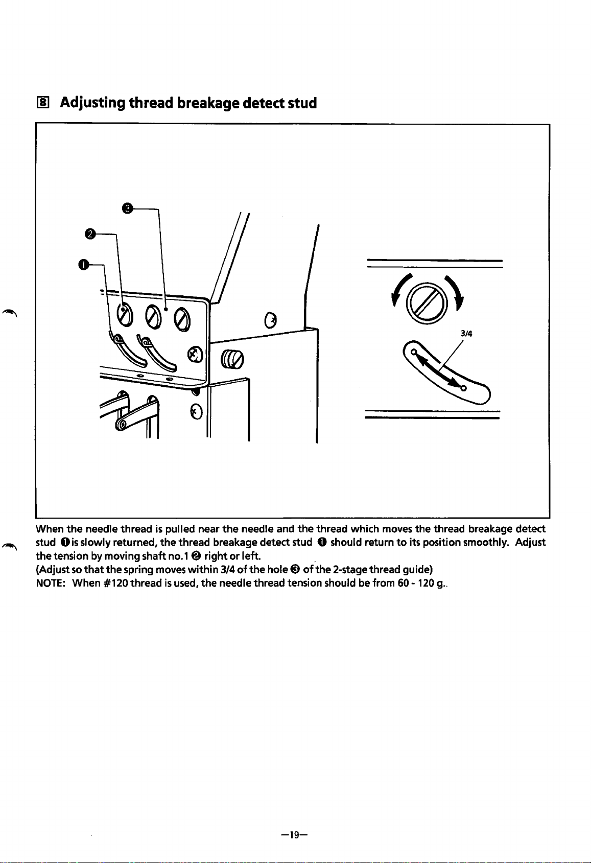
[!] Adjusting thread breakage detect
stud
3/4
When
the
needle thread
is
pulled near
the
needle and
the
thread which moves
the
thread breakage detect
stud
Ois
slowly returned,
the
thread breakage detect stud 0 should return
to
its position smoothly. Adjust
the
tension by moving shaft no.1@
right
or
left. _
{Adjust
so
that
the
spring moves
within
3/4
of
the
hole@)
of
the
2-stage thread guide)
NOTE:
When #120 thread
is
used,
the
needle thread tension should be from
60-
120
g
..
-19-
From the library of: Superior Sewing Machine & Supply LLC
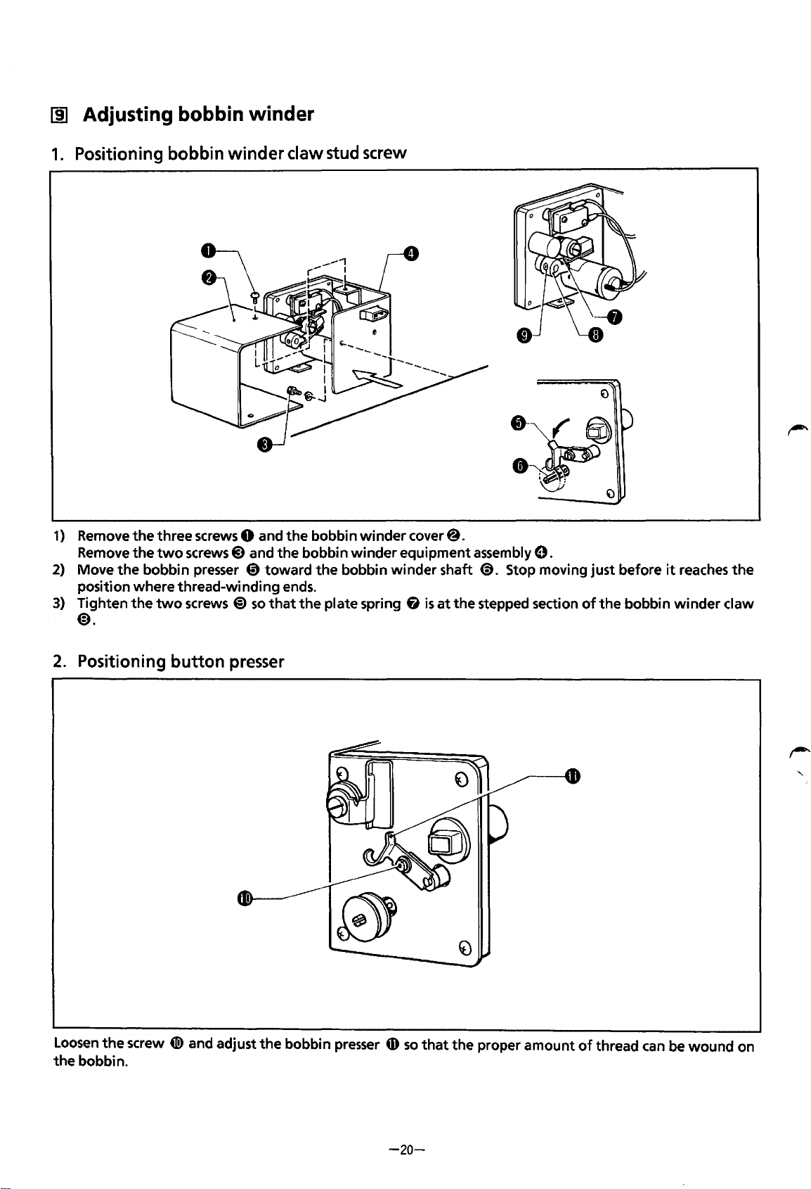
[j] Adjusting bobbin winder
1.
Positioning bobbin
winder
claw stud screw
1)
Remove
the
three screws 0 and
the
bobbin
winder
cover@.
Remove
the
two
screws 8 and
the
bobbin
winder
equipment assembly
9.
2)
Move
the
bobbin presser @)toward
the
bobbin
winder
shaft
<9.
Stop moving just before
it
reaches
the
position where thread-winding ends.
3)
Tighten
the
two
screws
@)
so
that
the
plate spring
fi
is
at
the stepped section
of
the
bobbin
winder
claw
@).
2.
Positioning
button
presser
Loosen
the
screw
41!)
and adjust
the
bobbin presser
tD
so
that
the
proper
amount
of
thread
can
be
wound
on
the
bobbin.
-20-
From the library of: Superior Sewing Machine & Supply LLC
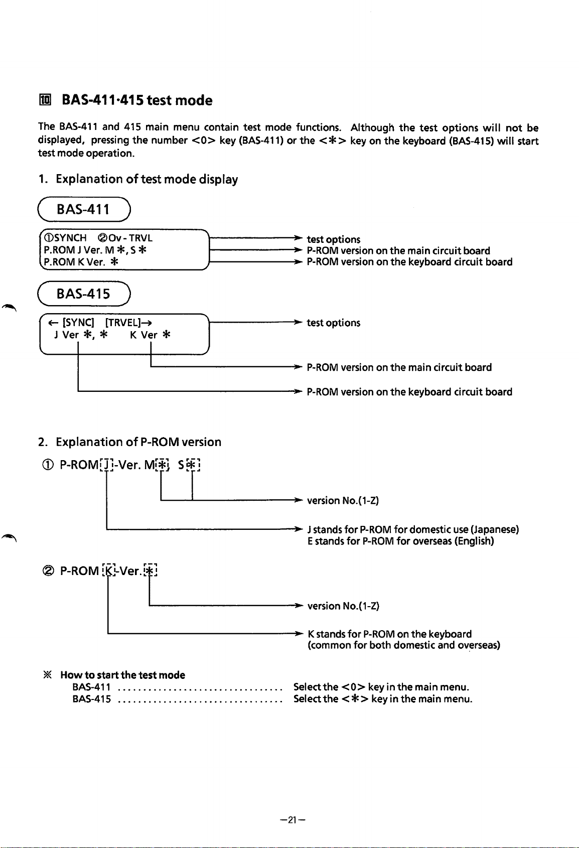
rml
BAS-411·415 test mode
The
BAS-411
and 415 main menu contain test mode functions. Although
the
test
options
will
not
be
displayed, pressing
the
number
<0>
key
(BAS-411)
or
the<*>
key on
the
keyboard
(BAS-415)
will
start
test mode operation.
1.
Explanation
of
test mode display
(
BAS-411
)
/
(i)SYNCH
®Ov-
TRVL
P.ROM
J Ver. M
*•
S *
P.ROM
K Ver. *
( BAS-415 )
~
[SYNC]
[TRVEL]~
J Ver
*,
* K Ver *
I
l--------J~~oo-
test options
1------~_..~
P-ROM
version on
the
main circuit board
1--------J~~oo-
P-ROM
version on the keyboard circuit board
\--------"'JIIoo-
test options
IL...------------J~~oo-
P-ROM
version on
the
main circuit board
'------------------J~~oo-
P-ROM
version on
the
keyboard circuit board
2.
Explanation
of
P-ROM
version
CD
P-ROM[]J]-Ver.
M[*r.j_S~.....__r]
___
....,.
- - •: version No.(1-Z)
- J stands
for
P-ROM
for
domestic
use
(Japanese)
E stands
for
P-ROM
for
overseas (English)
®
P-ROM
[K[}Ver.[r.__]
_______
_....,..
- : version
No.(1-Z)
'---------------~-
K stands
for
P-ROM
on the keyboard
(common
for
both domestic and
ov~rseas)
*
Howtostartthetestmode
BAS-411
.................................
Selectthe<O>keyinthemainmenu.
BAS-41
5 . . . . . . . . . . . . . . . . . . . . . . . . . . . . . . . . . Select
the
< * > key in
the
main menu.
-21-
From the library of: Superior Sewing Machine & Supply LLC
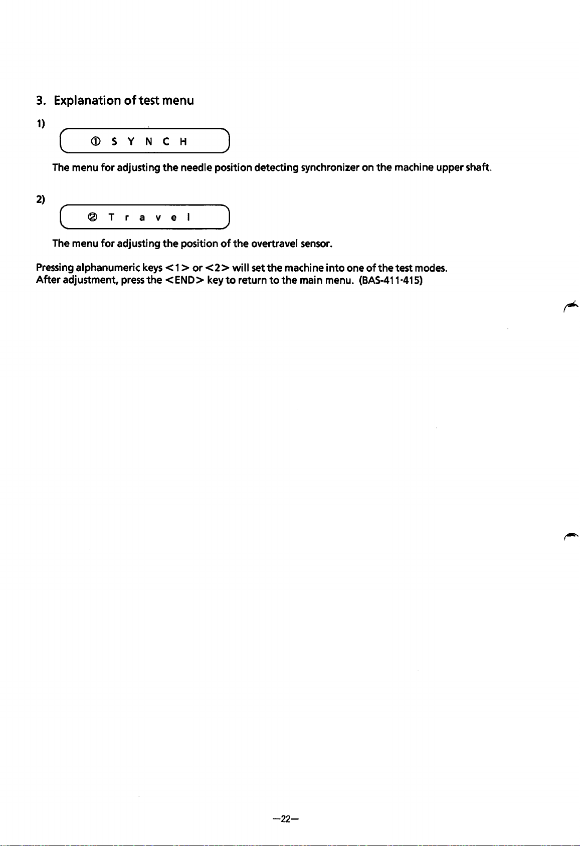
3.
Explanation
of
test menu
1)
( ____
~
___ s __ v __ N
__
c ___ H
_____
)
The
menu
for
adjusting
the
needle
position
detecting
synchronizer
on
the
machine
upper
shaft.
2)
(
____
®
___
r
___
r
__
a
__
v
___
e
__
l
____
_,)
The
menu
for
adjusting
the
position
of
the
overtravel sensor.
Pressing
alphanumeric
keys < 1 >
or
< 2 > will set
the
machine
into
one
of
the
test
modes.
After
adjustment,
press
the
<END>
key
to
return
to
the
main
menu. (BAS-411·415)
-22-
From the library of: Superior Sewing Machine & Supply LLC
IDJ
Adjusting synchronizer
The
synchronizer detects
the
needle position and synchronizes
the
motion
of
the
needle and
the
holder
base.
When
the
emergency stop operates
after
the
power switch
is
turned on,
or
when
the
machine stops
after
thread trimming,
the
needle bar
will
be released in
the
jump
condition, and
the
thread take-up
will
stop
at
the
same position
as
the
other
8 needle bars.
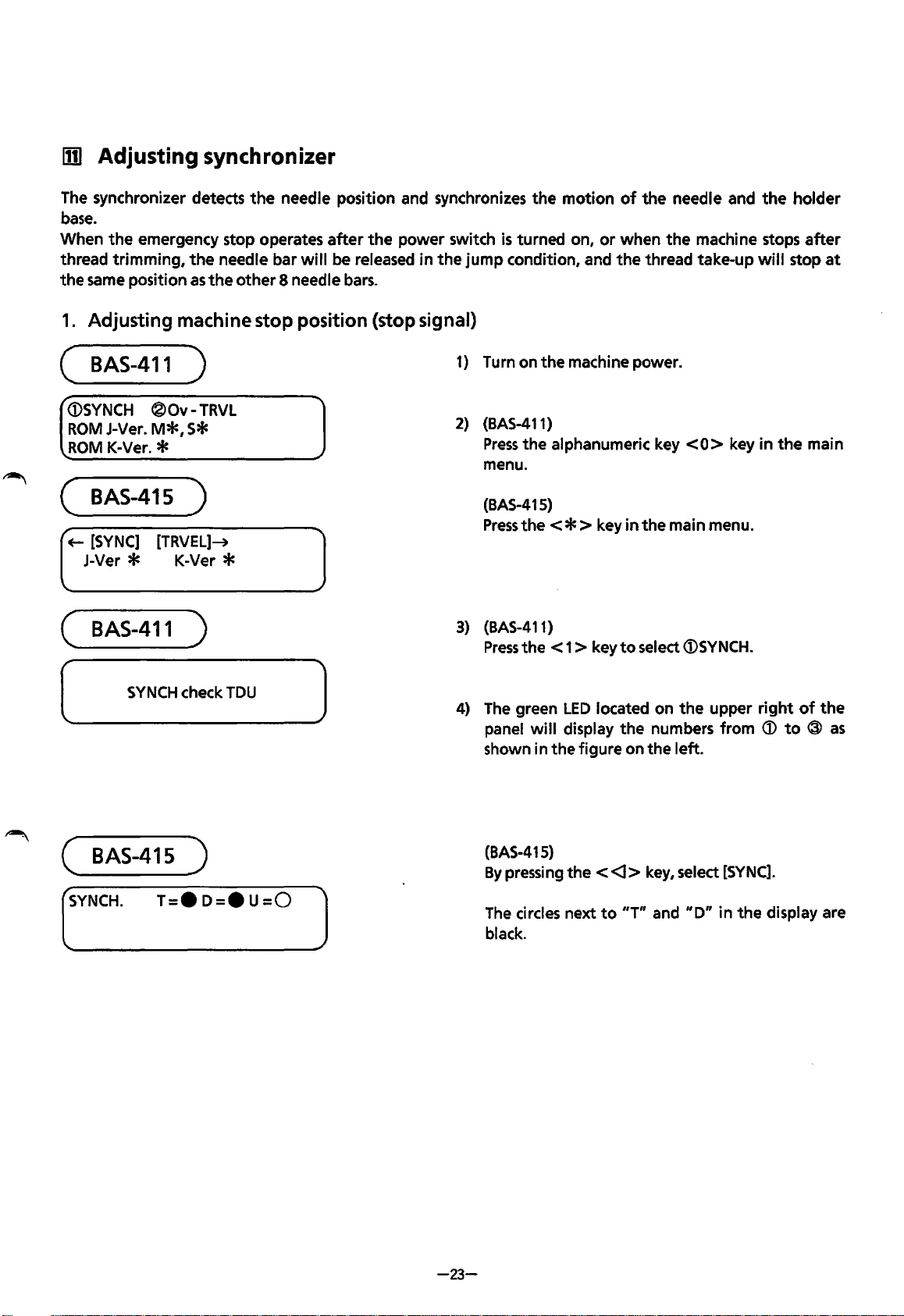
1.
Adjusting machine stop position (stop signal)
(
BAS-411
)
<DSYNCH
®Ov-
TRVL
ROM
J-Ver.
M*,
S*
ROM
K-Ver. *
(
BAS-415
)
+-
[SYNC]
[TRVEL]-+
J-Ver * K-Ver *
(
BAS-411
)
(
SYNCH
check
TDU
(
BAS-415
)
)
(_SY_N_C_H·
__
T_=_·_D_=_•_U_=_O
__
]
1) Turn on
the
machine power.
2)
(BAS-411)
Press
the
alphanumeric key
<0>
key
in
the
main
menu.
(BAS-415)
Press
the<*>
key
in
the main menu.
3)
(BAS-411)
Press
the
< 1 > key
to
select
<DSYNCH.
4)
The
green
LED
located on
the
upper
right
of
the
panel
will
display
the
numbers from
<D
to
®
as
shown in
the
figure on
the
left.
-23-
(BAS-415)
By
pressing
the
<
<l>
key, select
[SYNC].
The
circles next
to
"T"
and
"D"
in
the
display are
black.
From the library of: Superior Sewing Machine & Supply LLC
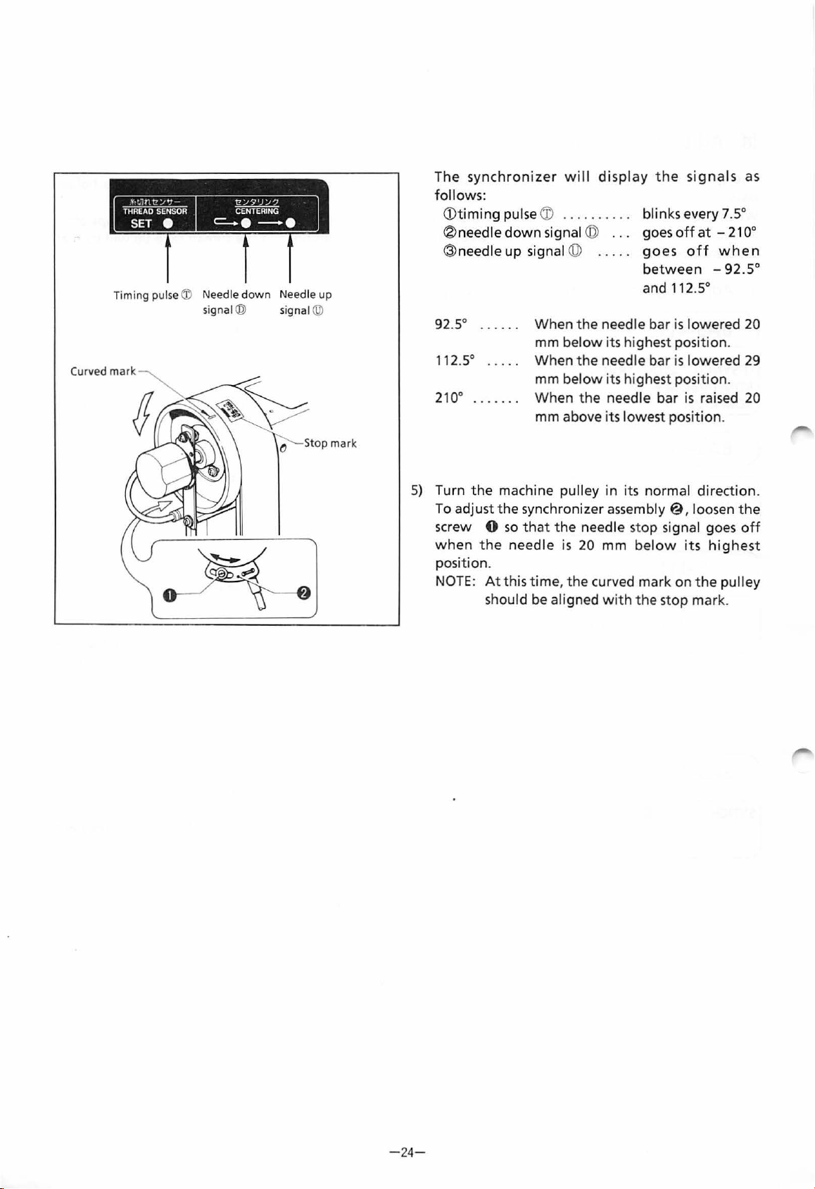
Timing pulse ® N
ee
dle do
wn
N
ee
dl e up
si
gnal@
si
gnal @
Curved mark
Stop
mar
k
The
synchronizer
wi
ll
disp
l
ay
the
signals
as
follows:
<D
timing
pulse
CD
.
...
.
....
.
® needle
down
signal ©
..
.
@needle
up
signal @
bl
in
ks every 7.5°
goes
off
at
-
21
oo
goes
off
when
between
-92.5
°
and 112.5°
92
.5° . . . . . . When t he needle bar
is
lowered 20
112S
mm
below
its highest position.
When the
needle bar is lowered
29
mm b
elow
its highest
pos
i
tio
n.
210
° . . . . . . .
When
the needle bar
is
raised
20
mm above its lowest position.
5)
Turn
the
machine pulley in i
ts
normal direct
ion
.
-24
-
To adjust
the
synchronizer
assem
bl
y@
, loosen the
sc
rew
0
so
th
at
the
needle s
top
si
gnal goes
off
when
the ne ed
le
is
20 mm bel
ow
it
s
highe
st
pos
ition
.
NOTE:
At
this time, the curved mark on
the
pulley
should
be aligned wi
th th
e st
op
mark.
From the library of: Superior Sewing Machine & Supply LLC
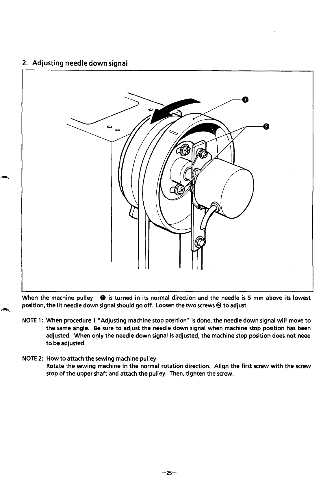
2.
Adjusting needle down signal
When
the
machine pulley 0
is
turned
in
its normal direction and
the
needle
is
5 mm above its lowest
position,
the
lit
needle
down
signal should
go
off.
Loosen
the
two
screws@
to
adjust.
NOTE
1:
When procedure 1 "Adjusting machine stop position"
is
done,
the
needle
down
signal
will
move
to
the
same
angle.
Be
sure
to
adjust
the
needle down signal when machine stop position
has
been
adjusted. When only
the
needle
down
signal
is
adjusted,
the
machine stop position does
not
need
to
be adjusted.
NOTE
2: How
to
attach
the
sewing machine pulley
Rotate
the
sewing machine
in
the
normal rotation direction. Align
the
first screw
with
the
screw
stop
of
the
upper shaft and attach
the
pulley. Then,
tighten
the
screw.
-25-
From the library of: Superior Sewing Machine & Supply LLC
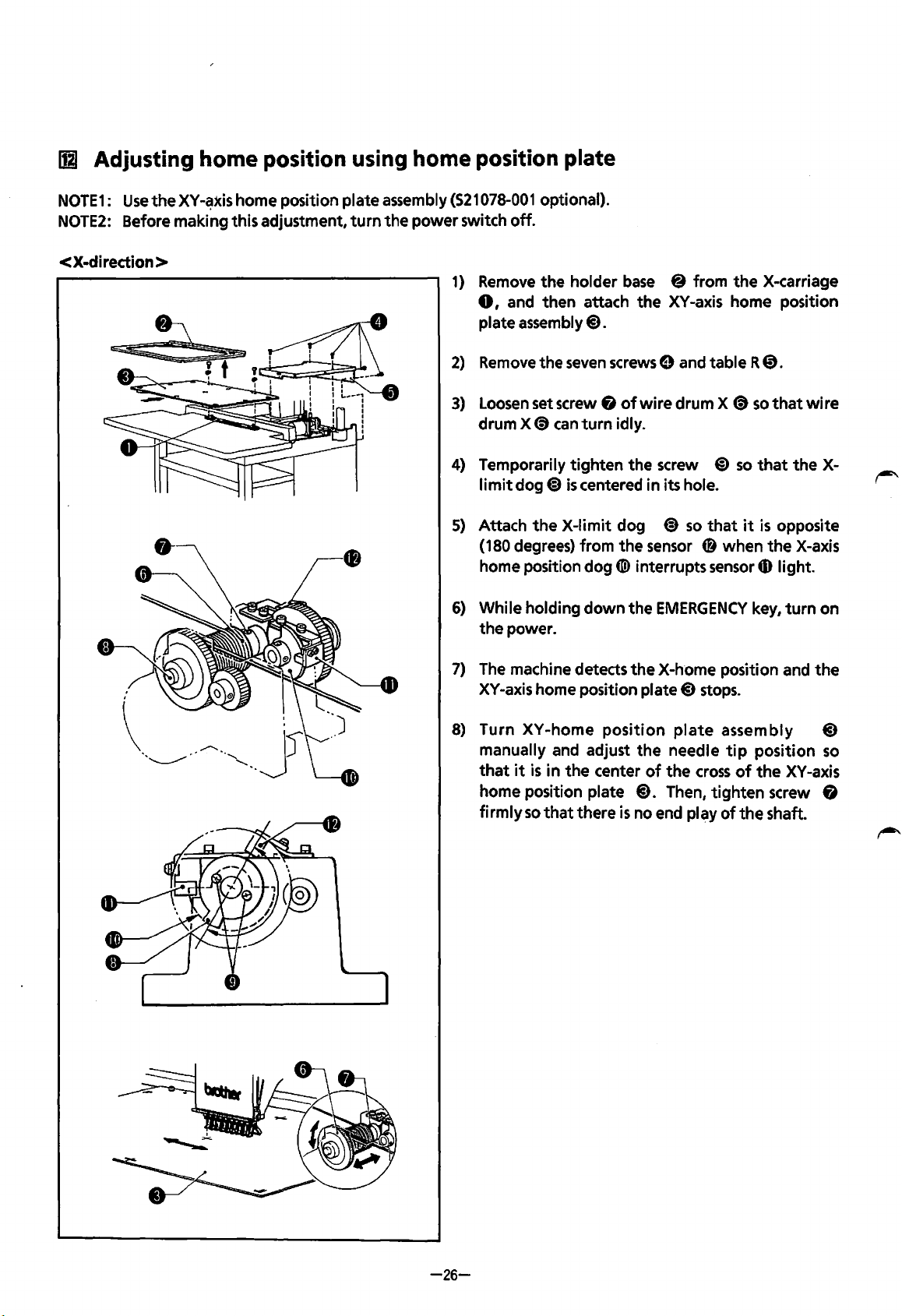
Ill
Adjusting
home
position using home position plate
NOTE1:
Use
the
XY-~xis
home position plate assembly
(521078-001
optional).
NOTE2:
Before making this adjustment,
turn
the power switch
off.
< X-direction >
1)
Remove
the holder
base
8 from
the
X-carriage
0,
and then attach the
XY
-axis home position
plate
assembly@).
2)
Remove
the
seven
screws
0 and table R
0.
3)
Loosen
set screw &
of
wire drum X
<9
so
that
wire
drum X
<9
can
turn
idly.
4)
Temporarily tighten the screw
@)
so
that
the
X-
limit
dog~
is
centered in its hole.
5)
Attach
the
X-limit dog
~
so
that
it
is
opposite
(180 degrees) from
the
sensor
CD
when
the
X-axis
home position
dog([!) interrupts
sensor
4D
light.
6)
While holding down the
EMERGENCY
key,
turn
on
the power.
7)
The
machine detects
the
X-home position and
the
XY-axis home position plate@)
stops.
8)
Turn XY-home
position
plate
assembly
@)
-26-
manually and adjust
the
needle
tip
position
so
that
it
is
in
the
center
of
the
cross
of
the
XV
-axis
home position plate
@).
Then, tighten screw &
firmly
so
that
there
is
no end play
of
the
shaft.
From the library of: Superior Sewing Machine & Supply LLC
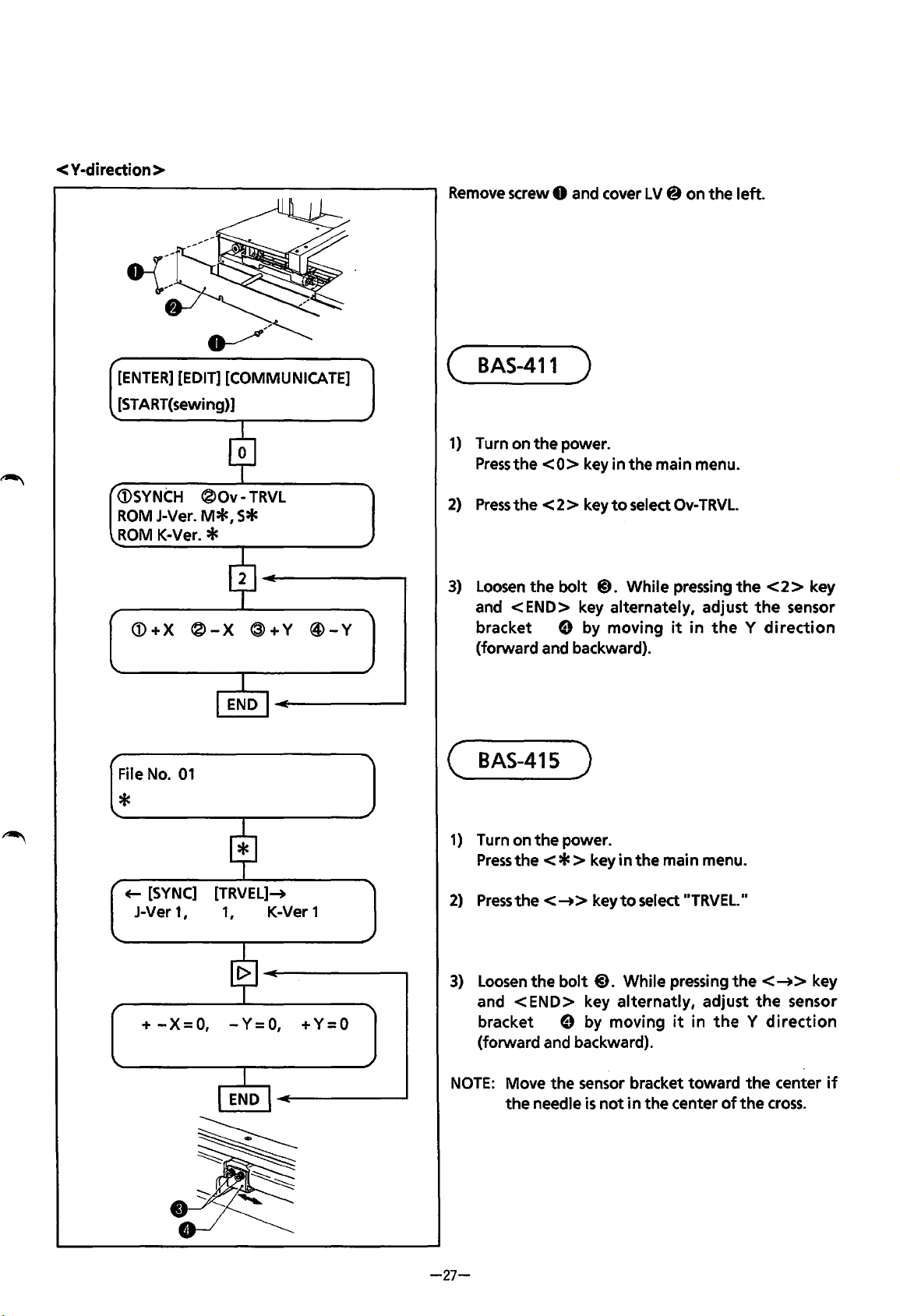
< Y·diredion >
[ENTER]
[EDIT]
[COMMUNICATE]
[START(sewing)]
<DSYNCH
®Ov-
TRVL
ROM
J-Ver.
M*,
S*
ROM
K-Ver. *
<D+X
®-X
®+Y
@-Y
File
No.
01
*
~
[SYNC]
[TRVEL]-+
J-Ver 1 I 1
1
K-Ver 1
+
-X=
0,
- Y =
0,
+ Y = 0
Remove
screw 0 and cover LV@ on the left.
(
BAS-411
)
1)
Turn on the power.
Press
the
<0>
key in the main menu.
2)
Press
the
< 2 > key
to
select
Ov-
TRVL.
3)
Loosen
the
bolt
@).
While pressing
the
<2>
key
and
<END>
key alternately, adjust
the
sensor
bracket
e by moving
it
in
the
y
direction
(forward and backward).
(
BAS-415
)
1)
Turn on
the
power.
Press
the<*>
key
in
the main menu.
2)
Press
the<-+>
key
to
select
..
TRVEL.
..
3)
Loosen
the bolt@). While pressing
the<-+>
key
and
<END>
key alternatly, adjust
the
sensor
bracket
e by moving
it
j n
the
y
direction
(forward and backward).
NOTE:
Move the sensor bracket toward
the
center
if
the
needle
is
not
in
the center
of
the
cross.
-27-
From the library of: Superior Sewing Machine & Supply LLC
 Loading...