


BAS-341H
Table of contents
 Loading...
INSTRUCTION MANUALINSTRUCTION MANUAL
BAS-341H
BAS-342H
Please read this manual before using the machine.
Please keep this manual within easy reach for quick reference.
DIRECT DRIVE
PROGRAMMABLE ELECTRONIC PATTERN SEWER

Thank you very much for buying a BROTHER sewing machine. Before using your new machine,
please read the safety instructions below and the explanations given in the instruction manual.
With industrial sewing machines, it is normal to carry out work while positioned directly in front of
moving parts such as the needle and thread take-up lever, and consequently there is always a
danger of injury that can be caused by these parts. Follow the instructions from training personnel
and instructors regarding safe and correct operation before operating the machine so that you will
know how to use it correctly.
BAS-341H, BAS-342H
SAFETY INSTRUCTIONS
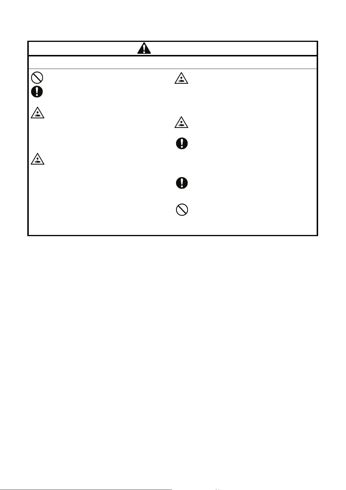
[1] Safety indications and their meanings
This instruction manual and the indications and symbols that are used on the machine itself are provided in order to ensure
safe operation of this machine and to prevent accidents and injury to yourself or other people.
The meanings of these indications and symbols are given below.
Indications
DANGER
The instructions which follow this term indicate situations where failure to follow the
instructions will result in death or serious injury.
WARNING
CAUTION
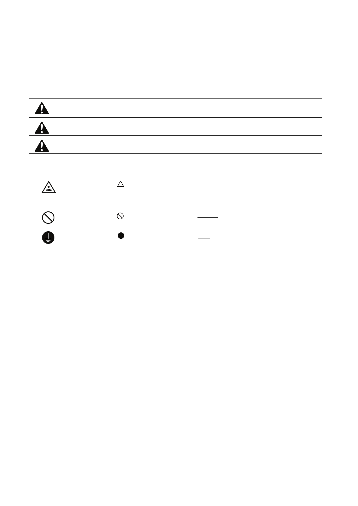
Symbols
・・・・・・
・・・・・・
・・・・・・
The instructions which follow this term indicate situations where failure to follow the
instructions could result in death or serious injury.
The instructions which follow this term indicate situations where failure to follow the
instructions may result in minor or moderate injury.
This symbol ( ) indicates something that you should be careful of. The picture inside the triangle
indicates the nature of the caution that must be taken.
(For example, the symbol at left means “beware of injury”.)
This symbol ( ) indicates something that you must not do.
This symbol ( ) indicates something that you must do. The picture inside the circle indicates the
nature of the thing that must be done.
(For example, the symbol at left means “you must make the ground connection”.)
BAS-341H, BAS-342H
i
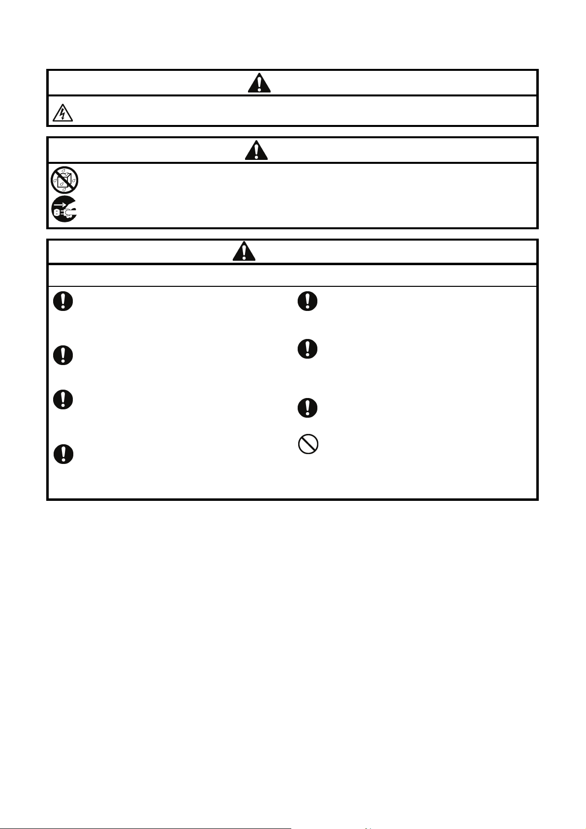
[2] Notes on safety
Wait at least 5 minutes after turning off the power switch and disconnecting the power cord from the wall outlet
before opening the control box cover. Touching areas where high voltages are present can result in severe injury.
Do not allow any liquids to get onto this sewing machine, otherwise fire, electric shocks or operating problems may
occur.
If any liquid gets inside the sewing machine (machine head or control box), immediately turn off the power and
disconnect the power plug from the electrical outlet, and then contact the place of purchase or a qualified
technician.
DANGER
WARNING
CAUTION
Environmental requirements
Use the sewing machine in an area which is free from
sources of strong electrical noise such as electrical
line noise or static electric noise.
Sources of strong electrical noise may cause
problems with correct operation.
Any fluctuations in the power supply voltage should
be within ±10% of the rated voltage for the machine.
Voltage fluctuations which are greater than this may
cause problems with correct operation.
The power supply capacity should be greater than the
requirements for the sewing machine's power
consumption.
Insufficient power supply capacity may cause
problems with correct operation.
The pneumatic delivery capability should be greater
than the requirements for the sewing machine's total
air consumption.
Insufficient pneumatic delivery capability may cause
problems with correct operation.
The ambient temperature should be within the range
of 5°C to 35°C during use.
Temperatures which are lower or higher than this
may cause problems with correct operation.
The relative humidity should be within the range of
45% to 85% during use, and no dew formation should
occur in any devices.
Excessively dry or humid environments and dew
formation may cause problems with correct operation.
In the event of an electrical storm, turn off the power
and disconnect the power cord from the wall outlet.
Lightning may cause problems with correct operation.
Do not connect anything to the USB port other than
the USB memory. If this is not observed, problems
with operation may result.
ii
BAS-341H, BAS-342H
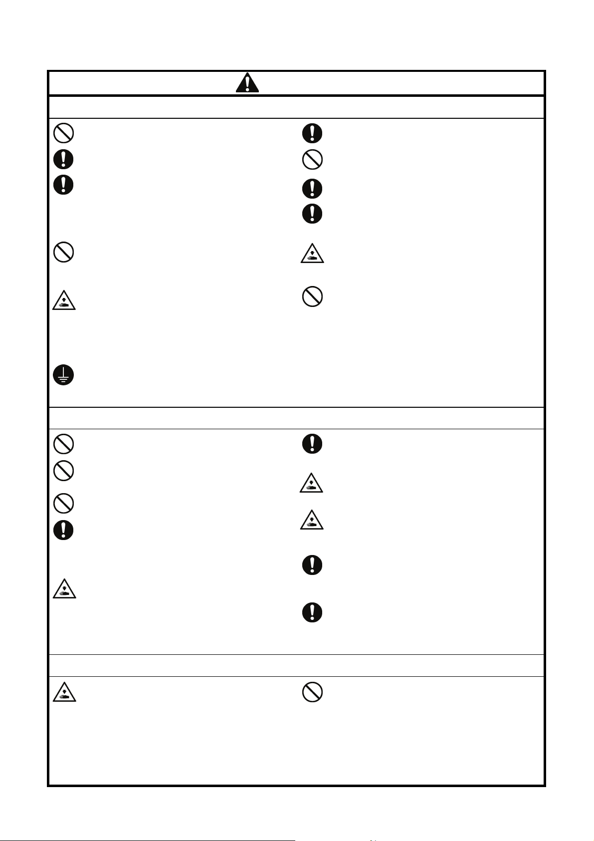
CAUTION
Installation
Machine installation should only be carried out by a
qualified technician.
Contact your Brother dealer or a qualified electrician
for any electrical work that may need to be done.
The sewing machine weighs approximately 160 kg.
Use equipment such as a crane or hoist when
installing the machine head and adjusting the height
of the table.
If you try to lift the machine head yourself, it may
cause injuries such as back injury.
Do not connect the power cord until installation is
complete. If the foot switch is depressed by mistake,
the sewing machine might start operating and injury
could result.
Hold the machine head with both hands when tilting it
back or returning it to its original position.
In addition, do not subject the machine head to extra
force while it is tilted back. If this is not observed, the
machine head may become unbalanced and fall
down, and serious injury or damage to the sewing
machine may result.
Be sure to connect the ground. If the ground
connection is not secure, you run a high risk of
receiving a serious electric shock, and problems with
correct operation may also occur.
All cords should be secured at least 25 mm away
from any moving parts. Furthermore, do not
excessively bend the cords or secure them too firmly
with staples, otherwise there is the danger that fire or
electric shocks could occur.
Install the safety covers to the machine head and
motor.
If using a work table which has casters, the casters
should be secured in such a way so that they cannot
move.
Use a table with a height of 84 cm or less. If the table
is too high, the machine head may become
unbalanced and fall down, and serious injury or
damage to the sewing machine may result.
Be sure to wear protective goggles and gloves when
handling the lubricating oil and grease, so that they
do not get into your eyes or onto your skin. If the oil
and grease get into your eyes or onto your skin,
inflammation can result.
Furthermore, do not drink or eat the lubricating oil or
grease. They may cause diarrhea or vomiting.
Keep the oil out of the reach of children.
Sewing
To prevent problems, do not use objects with sharp
points to operate the LCD panel.
This sewing machine should only be used by
operators who have received the necessary training
in safe use beforehand.
The sewing machine should not be used for any
applications other than sewing.
Be sure to wear protective goggles when using the
machine.
If goggles are not worn, there is the danger that if a
needle breaks, parts of the broken needle may enter
your eyes and injury may result.
Turn off the power switch at the following times. If the
foot switch is depressed by mistake, the sewing
machine might start operating and injury could result.
• When replacing the bobbin and needle
• When not using the machine and when leaving the
machine unattended
Cleaning
Turn off the power switch before carrying out
cleaning. If the foot switch is depressed by mistake,
the sewing machine might start operating and injury
could result.
If using a work table which has casters, the casters
should be secured in such a way so that they cannot
move.
Attach all safety devices before using the sewing
machine. If the machine is used without these
devices attached, injury may result.
Do not touch any of the moving parts or press any
objects against the machine while sewing, as this
may result in personal injury or damage to the
machine.
If an error occurs in machine operation, or if abnormal
noises or smells are noticed, immediately turn off the
power switch. Then contact your nearest Brother
dealer or a qualified technician.
If the machine develops a problem, contact your
nearest Brother dealer or a qualified technician.
Be sure to wear protective goggles and gloves when
handling the lubricating oil and grease, so that they
do not get into your eyes or onto your skin. If the oil
and grease get into your eyes or onto your skin,
inflammation can result.
Furthermore, do not drink or eat the lubricating oil or
grease. They may cause diarrhea or vomiting.
Keep the oil out of the reach of children.
BAS-341H, BAS-342H
iii
CAUTION
Maintenance and inspection
Maintenance and inspection of the sewing machine
should only be carried out by a qualified technician.
Ask your Brother dealer or a qualified electrician to
carry out any maintenance and inspection of the
electrical system.
Turn off the power switch and disconnect the power
cord before carrying out the following operations. If
the foot switch is depressed by mistake, the sewing
machine might start operating and injury could result.
• Inspection, adjustment and maintenance
• Replacing consumable parts such as the rotary
hook
Disconnect the air hoses from the air supply and wait
for the needle on the pressure gauge to drop to “0”
before carrying out inspection, adjustment and repair
of any parts which use the pneumatic equipment.
Hold the machine head with both hands when tilting it
back or returning it to its original position.
In addition, do not subject the machine head to extra
force while it is tilted back. If this is not observed, the
machine head may become unbalanced and fall
down, and serious injury or damage to the sewing
machine may result.
If the power switch needs to be left on when carrying
out some adjustment, be extremely careful to observe
all safety precautions.
When replacing parts and installing optional
accessories, be sure to use only genuine Brother
parts.
Brother will not be held responsible for any accidents
or problems resulting from the use of non-genuine
parts.
If any safety devices have been removed, be
absolutely sure to re-install them to their original
positions and check that they operate correctly before
using the machine.
To prevent accidents and problems, do not modify
the machine yourself.
Brother will not be held responsible for any accidents
or problems resulting from modifications made to the
machine.
iv
BAS-341H, BAS-342H
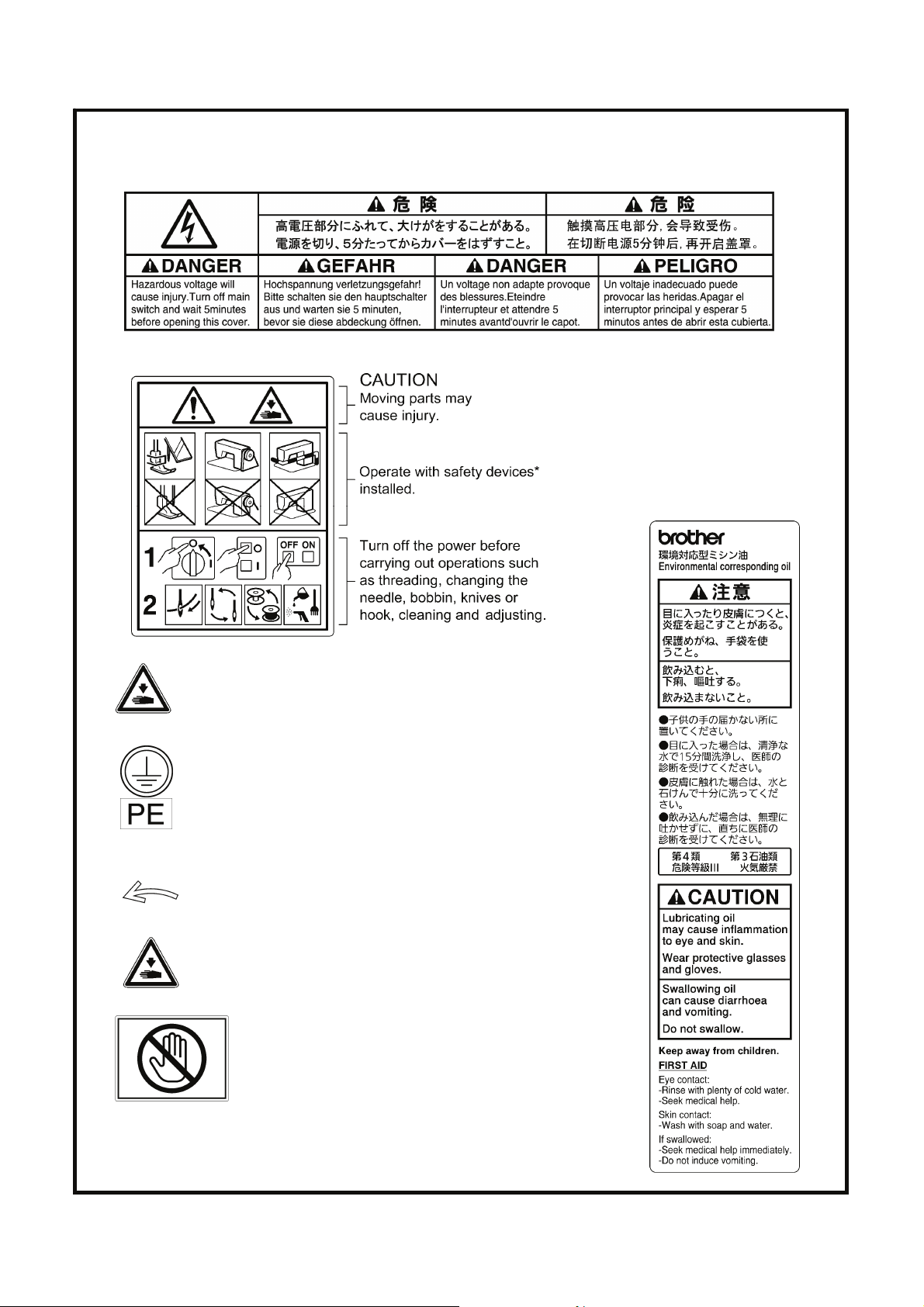
[3] Warning labels
The following warning labels appear on the sewing machine.
Please follow the instructions on the labels at all times when using the machine. If the labels have been removed or are
difficult to read, please contact your nearest Brother dealer.
1
2
3
4
Be careful to avoid injury from moving parts.
Be sure to connect the ground.
If the ground connection is not secure, you run a high
risk of receiving a serious electric shock, and problems
with correct operation may also occur.
.
*Safety devices
Devices such as eye guard, finger guard,
thread take-up cover, motor cover,
X motor cover, rear cover, solenoid cover,
inner cover, outer cover, fixed cover and
gas spring support cover
8
5
6
7
Direction of operation
Be careful not to get your hand caught when tilting back
the machine head and returning it to its original position.
Do not hold, otherwise problems with
operation or injury may occur.
BAS-341H, BAS-342H
v
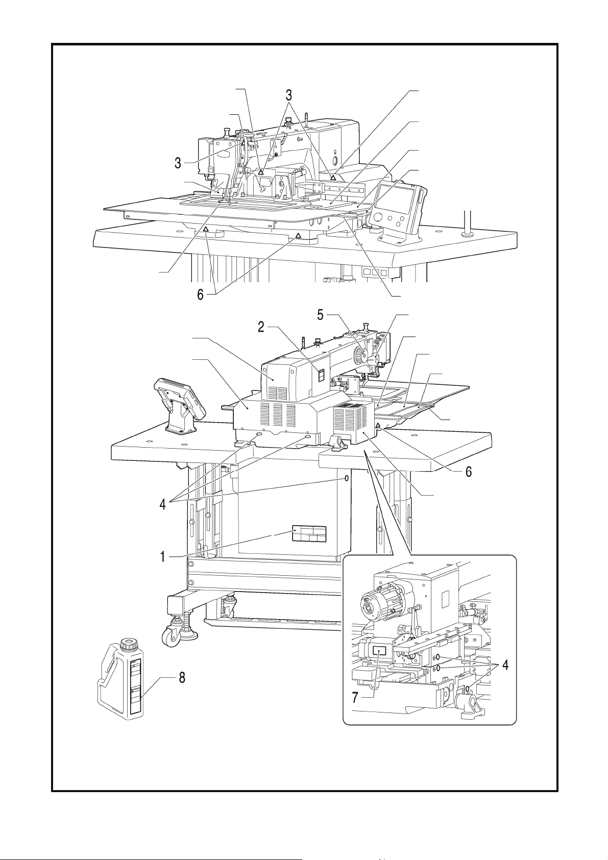
Eye guard
Rear cover FL
Thread take-up cover
Rear cover FR
Inside cover R
Middle cover
Outside cover
Finger guard
Fixed cover
Solenoid cover
Motor cover
Rear cover
Inside cover L
Middle cover
Outside cover
Fixed cover
X motor cover
vi
3461B
BAS-341H, BAS-342H

CONTENTS
1. NAMES OF MAJOR PARTS ................ 1
2. SPECIFICATIONS ................................ 2
3. INSTALLATION.................................... 3
3-1. Table processing diagram ................................ 4
3-2. Installing the control box................................... 5
3-3. Installing the oil pan and support lever base.... 6
3-4. Installing the machine head.............................. 6
3-5. Tilting back and returning the machine head ... 7
3-6. Installing the gas spring .................................. 8
3-7. Installing the LCD panel ................................... 9
3-8. Installing the solenoid valve assembly ............. 10
3-9. Connecting the air tubes................................... 10
3-10. Installing the air hose...................................... 10
3-11. Installing the two-pedal foot switch................. 11
3-12. Installing the cords.......................................... 11
3-13. Connecting the ground wire............................ 15
3-14. Securing the cords and air tubes.................... 16
3-15. Connecting the power cord............................. 17
3-16. Installing the eye guard .................................. 20
3-17. Installing the cotton stand...............................20
3-18. Lubrication ...................................................... 21
3-19. Checking the machine head switch................ 22
4. PREPARATION BEFORE SEWING.....23
4-1. Installing the needle.......................................... 23
4-2. 2-pedal foot switch operation method .............. 23
4-3. Threading the upper thread .............................. 24
4-4. Winding the lower thread..................................26
4-5. Installing the bobbin case................................. 27
4-6. Thread tension.................................................. 28
4-6-1. Lower thread tension .............................. 28
4-6-2. Upper thread tension .............................. 29
4-7. Starting up ........................................................30
4-8. Setting 2-step operation for the work clamp.....31
7.STANDARD ADJUSTMENTS................36
7-1. Adjusting the sensitivity of the thread breakage
sensor ...............................................................36
7-2. Thread take-up spring.......................................37
7-3. Arm thread guide R...........................................37
7-4. Adjusting the needle bar height ........................38
7-5. Adjusting the needle and rotary hook timing.....38
7-6. Adjusting the driver (needle guard) position .....39
7-7. Adjusting the clearance between the
needle and rotary hook tip ................................39
7-8. Adjusting the shuttle race thread guide ............39
7-9. Rotary hook lubrication amount ........................40
7-10. Adjusting the position of the movable knife ....41
7-11. Replacing the movable and fixed knives ........43
7-12. Installing the feed plate ...................................44
7-13. Adjusting the thread wiper ..............................44
7-14. Intermittent presser foot installation position ..45
7-15. Adjusting the intermittent presser foot ............45
7-16. Adjusting the work clamp lift amount ..............47
7-17. Adjusting the air pressure ...............................47
7-18. Adjusting the speed controller.........................48
7-19. If processing the work clamps and the
feed plate to a shape that matches the
sewing pattern ................................................49
8. LIST OF ERROR CODES.....................51
9. TROUBLESHOOTING.......................... 57
5. SEWING................................................32
5-1. Sewing .............................................................. 32
5-2. Using the STOP switch..................................... 33
6. CLEANING ...........................................34
6-1. Cleaning the rotary hook ..................................34
6-2. Draining the oil.................................................. 34
6-3. Cleaning the regulator ...................................... 35
6-4. Checking the control box air inlet ports ............ 35
6-5. Cleaning the eye guard ................................... 35
6-6. Checking the needle ....................................... 35
6-7. Lubrication ........................................................ 35
BAS-341H, BAS-342H
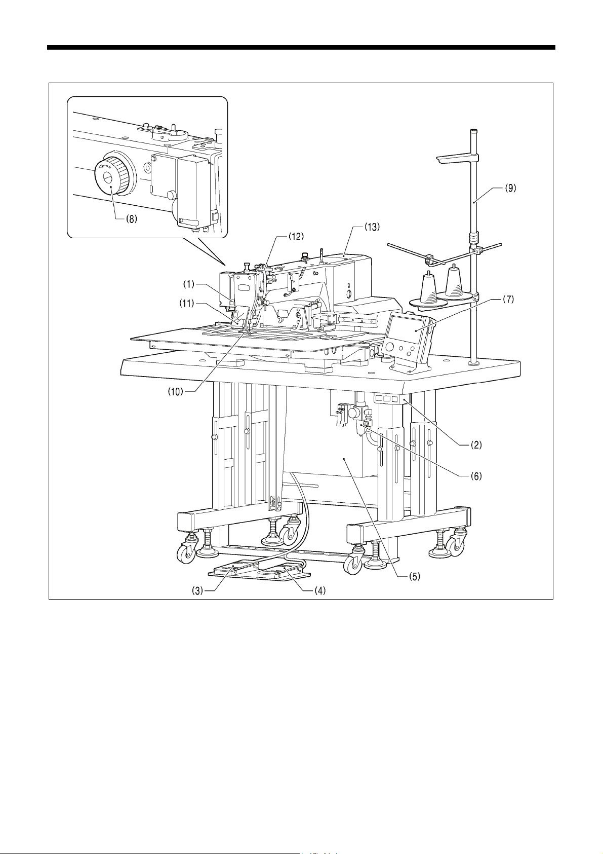
1. NAMES OF MAJOR PARTS
1. NAMES OF MAJOR PARTS
(1) STOP switch
(2) Power switch (10) Finger guard
(3) Work clamp switch (11) Eye guard
(4) Start switch (12) Thread take-up cover
(5) Control box (13) Motor cover
(6) Solenoid valve
(7) LCD panel
(8) Pulley
(9) Cotton stand
Safety devices:
3462B
1
BAS-341H, BAS-342H

2. SPECIFICATIONS
2. SPECIFICATIONS
Sewing machine Lock stitch pattern tacking sewing machine
Stitch formation Single needle lock stitch
Max. sewing speed 2,800 sti/min
Max. sewing area (XxY) BAS-341H: 250 x 160 mm BAS-342H: 300 x 200 mm
Feed mechanism Intermittent feed, pulse motor drive
Stitch length
Maximum No. of stitches 20,000 stitches (per program)
No. of sewing data items
that can be stored
Work clamp lift method Pneumatic cylinder method
Work clamp height Max. 30 mm
2-step work clamp Integrated-type work clamp
Intermittent presser foot lift
amount
Intermittent presser foot
stroke
Hook Double-capacity shuttle hook
Wiper device Standard equipment
Thread trimmer Standard equipment
Digital tension Standard equipment
Thread breakage detector Standard equipment
Cycle programs 30
Motor 550 W AC servo motor
Weights
Power source
Air pressure 0.5 MPa 1.8 l/min.
(*1) The number of data items and stitches that can be stored will vary depending on the number of stitches in each
program.
No guarantees of operation can be given for any media.
999 (Internal memory, SD card, USB memory) (*1)
2 − 4.5 mm, 4.5 − 10 mm or 0 (Default setting 3 mm)
Machine head Approx. 160 kg, LCD panel Approx. 0.8 kg
Control box 12 kg (Differs depending on destination)
Single-phase 220V / 230V, 3-phase 220V / 380V / 400V
(For three-phase 380 V/400 V, the trans box is required.)
0.05 − 12.7 mm
22 mm
BAS-341H, BAS-342H
2
3. INSTALLATION
3. INSTALLATION
CAUTION
Machine installation should only be carried out by a
qualified technician.
Contact your Brother dealer or a qualified electrician
for any electrical work that may need to be done.
The sewing machine head weighs approximately 160
kg.
Use equipment such as a crane or hoist when
installing the machine head and adjusting the height of
the table.
If you try to lift the machine head yourself, it may cause
injuries such as back injury.
Do not connect the power cord until installation is
complete.
If the foot switch is depressed by mistake, the sewing
machine might start operating and injury could result.
If using a work table which has casters, the casters
should be secured in such a way so that they cannot
move.
Use a table with a height of 84 cm or less. If the table
is too high, the machine head may become
unbalanced and fall down, and serious injury or
damage to the sewing machine may result.
Hold the machine head with both hands when tilting it
back or returning it to its original position.
In addition, do not subject the machine head to extra
force while it is tilted back. If this is not observed, the
machine head may become unbalanced and fall down,
and serious injury or damage to the sewing machine
may result.
All cords should be secured at least 25 mm away from
any moving parts. Furthermore, do not excessively
bend the cords or secure them too firmly staples,
otherwise there is the danger that fire or electric
shocks could occur.
Be sure to connect the ground. If the ground
connection is not secure, you run a high risk of
receiving a serious electric shock, and problems with
correct operation may also occur.
Install the safety covers to the machine head and
motor.
3
BAS-341H, BAS-342H
3. INSTALLATION
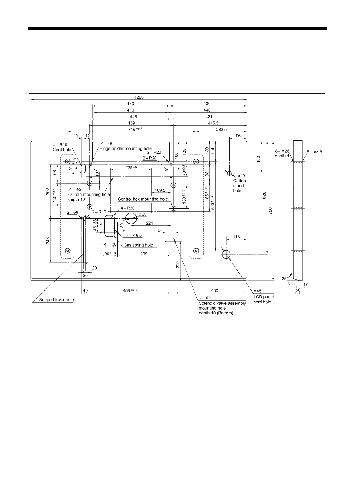
3-1. Table processing diagram
・ The thickness of the table should be at least 50 mm, and it should be strong enough to bear the weight and vibration of the
sewing machine.
・ If using casters, use ones which can bear the total weight of sewing machine and table.
・ Check that the control box is at least 10 mm away from the leg. If the control box and the leg are too close together, it may result
in incorrect sewing machine operation.
3635B
BAS-341H, BAS-342H
4
3. INSTALLATION
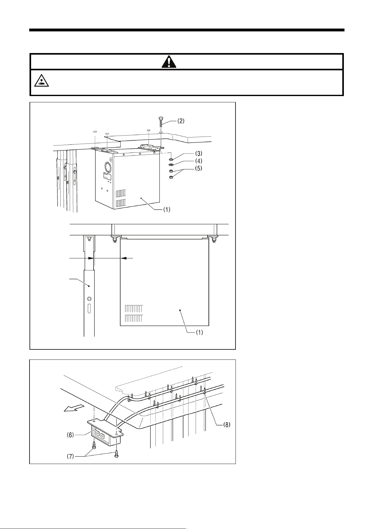
3-2. Installing the control box
The control box is heavy, so installation should be carried out by two or more people.
In addition, take steps to make sure that the control box does not fall down.
If this is not done, injury to feet or damage to the control box may result.
CAUTION
3606B
10mm or more
Leg
Operator
3599B
3608B
(1) Control box
(2) Bolts [4 pcs.]
(3) Plain washers [4 pcs.]
(4) Spring washers [4 pcs.]
(5) Nuts [8 pcs.]
NOTE:
Check that the control box (1) is at
least 10 mm away from the leg. If the
control box (1) and the leg are too
close together, it may result in
incorrect sewing machine operation.
(6) Power switch
(7) Wood screws [2 pcs.]
(8) Staples [7 pcs.]
NOTE:
Take care when tapping in the staples
(8) to make sure that they do not
pierce the power cord.
5
BAS-341H, BAS-342H
3-3. Installing the oil pan and support lever base
Table
3964M
3. INSTALLATION
(1) Oil pan
(2) Wood screws [4 pcs.]
(3) Oiler
(4) Support lever base
(5) Plain washers [2 pcs.]
(6) Spring washers [2 pcs.]
(7) Bolts [2 pcs.]
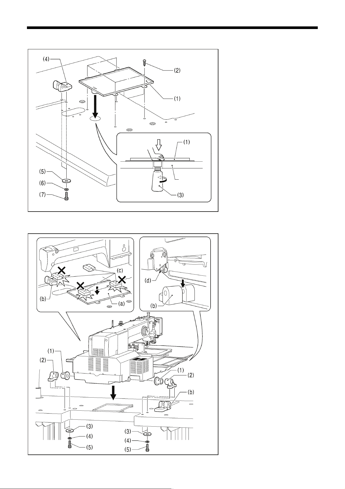
3-4. Installing the machine head
2585B
1. Place the machine head onto the
table.
NOTE:
・ Use a crane or hoist to install the
sewing machine.
・ Be careful of the following when
lowering the machine head onto the
table.
! Do not let any cords get clamped
between the machine head and
the table.
! Do not place the machine head
cushion (c) on top of the oil pan
(a) or the support lever base (b).
! Do not let the side (d) of the
machine head switch lever touch
the support lever base (b).
(1) Rubber bushes (2 pcs.)
(2) Hinge holders (2 pcs.)
(3) Plain washers [4 pcs.]
(4) Spring washers [4 pcs.]
(5) Bolts [4 pcs.]
(Continued on next page)
BAS-341H, BAS-342H
6
3. INSTALLATION
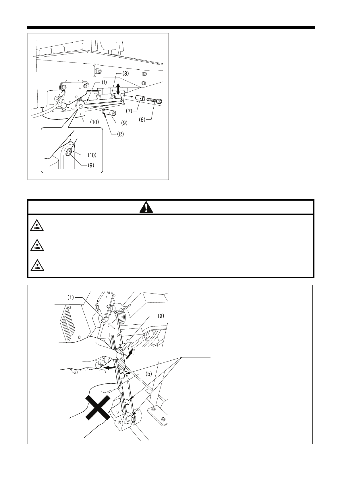
2. After placing the machine head onto the table, remove the
bolt (6) and the spacer (7).
* The bolt (6) and the spacer (7) are necessary for
securing the support lever (8) when the machine head is
removed from the table, so keep them in a safe place.
3. Pass the support lever shaft (9) through the hole in the
support lever base (10) and through the groove (f) in the
support lever (8), and push it in until it is flush with the
surface of the support lever base (10).
* Be sure to insert so that the groove (g) in the support
lever shaft (9) faces in the direction shown in the
illustration.
Flush
* If it is difficult to pass the support lever shaft (9) through
the groove (f) in the support lever (8), move the end of
the support lever (8) up and down while passing the
support lever shaft (9) through.
3601B
3-5. Tilting back and returning the machine head
CAUTION
Hold the machine head with both hands when tilting it back or returning it to its original position.
In addition, do not subject the machine head to extra force while it is tilted back. If this is not observed, the machine head
may become unbalanced and fall down, and serious injury or damage to the sewing machine may result.
Always be sure to engage the stopper of the support lever (1) when tilting back the machine head.
If the stopper is not engaged, the machine head may return to its original position and your hands may get caught and
injury may result.
When disengaging the stopper, hold it by the knob (a).
If you hold at the place indicated by (b), your hand will get caught between the support lever (1) and the table when the
machine head is returned to its original position and injury will result.
Disengaging
the stopper
Engaging
the stopper
The machine head can be tilted
back and returned to one of three
heights.
3967M
7
BAS-341H, BAS-342H
3-6. Installing the gas spring
3466B
Crane or hoist
Engaging
the stopper
3. INSTALLATION
Disengaging
the stopper
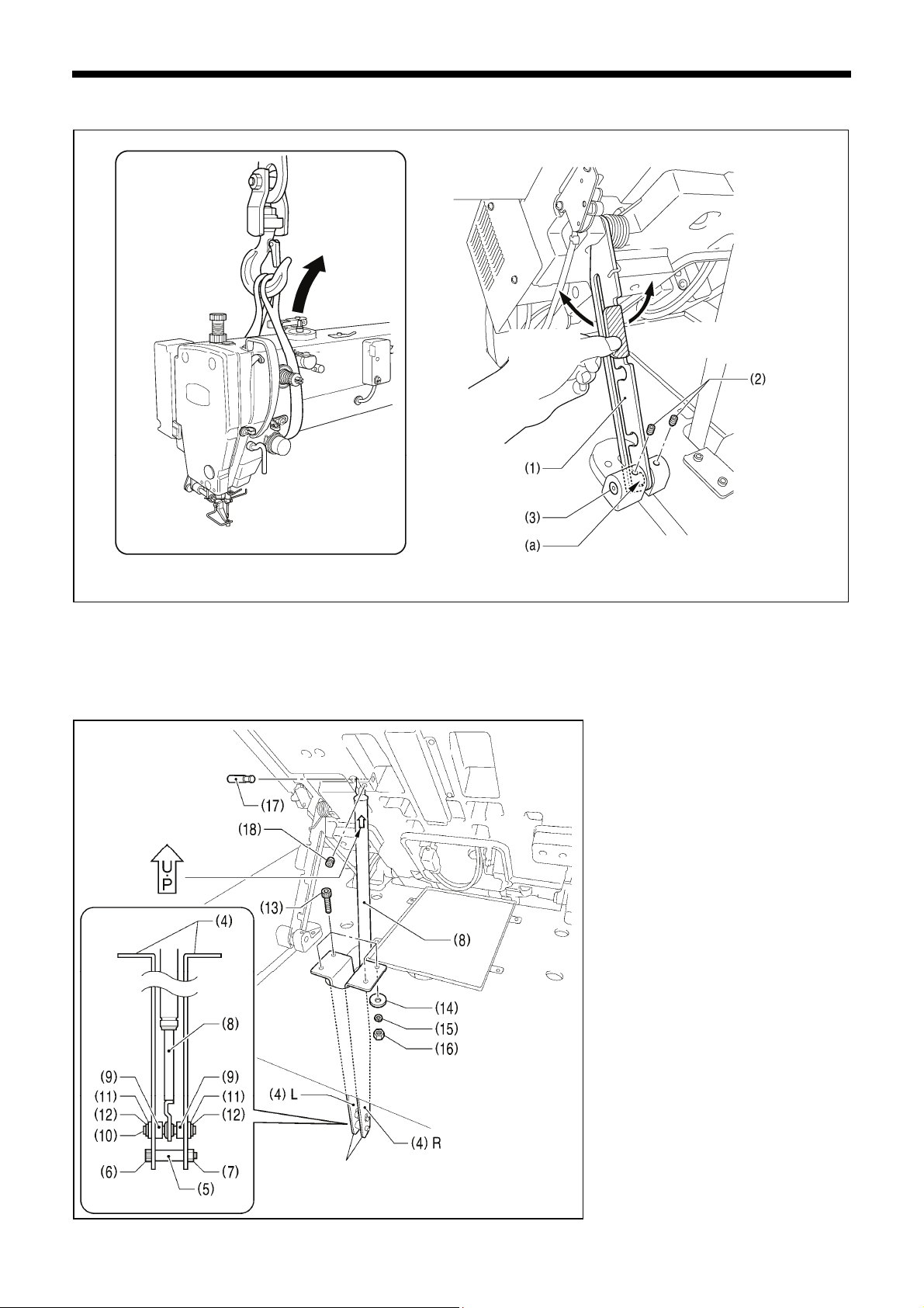
1. Tilt back the machine head, and then secure the support lever (1) at stopper position (a).
(Refer to "3-5. Tilting back and returning the machine head".)
NOTE: Use equipment such as a crane or hoist to tilt back the machine head.
2. Tighten the two set screws (2) to secure the support lever shaft (3).
Be sure to install so that
the side with “UP” on it is
facing upward.
(10) Gas spring shaft D
(11) Plain washers [2 pcs.]
(12) Retaining rings E [2 pcs.]
(13) Bolts [4 pcs.]
(14) Plain washers [4 pcs.]
(15) Spring washers [4 pcs.]
(16) Nuts [4 pcs.]
(17) Gas spring shaft U
(18) Set screw
* After installing the gas spring (8), gently
Note that the L and R
shapes are different.
2915B
3. Install the gas spring (8).
(4) Gas spring holders [L and R]
(5) Spacer
(6) Bolt
(7) Nut
(8) Gas spring
(9) Shaft collars [2 pcs.]
return the machine head to its original
position.
(Refer to "3-5. Tilting back and returning
the machine head".)
BAS-341H, BAS-342H
8
3. INSTALLATION
3-7. Installing the LCD panel
3574B
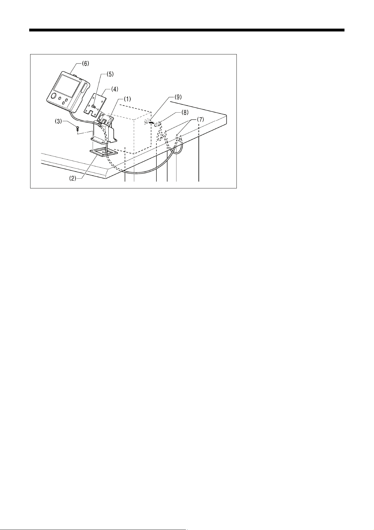
(1) Cradle
(2) Rubber cushion
(3) Wood screws [4 pcs.]
(4) Setting plate
(5) Flat screws [4 pcs.]
(6) LCD panel
(7) Staples [2 pcs.]
・ Pass the cord of the LCD panel (8)
through the table hole, and then
insert it into the (PANEL) connector
(9) on the side of the control box.
・ Tighten the four wood screws (3) so
that the thickness of the rubber
cushion (2) is 5 mm.
9
BAS-341H, BAS-342H
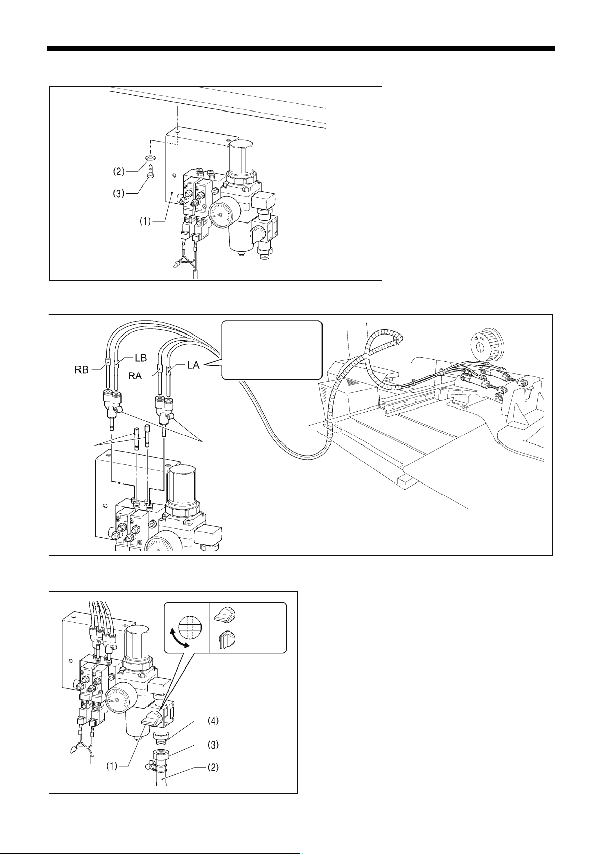
3-8. Installing the solenoid valve assembly
3-9. Connecting the air tubes
Plugs 4
Connect as shown in
the illustration while
checking the marks.
Branch unions Y
2562B
3. INSTALLATION
Install underneath the work table. (Refer
to "3-1. Table processing diagram" for the
installation positions.)
(1) Solenoid valve assembly
(2) Washers [2 pcs.]
(3) Wood screws [2 pcs.]
NOTE:
Make sure that the solenoid valve
assembly does not touch the control
box or the leg of the table.
2563B
3-10. Installing the air hose
Close
Open
2564B
BAS-341H, BAS-342H
1. Close the cock (1).
2. Turn the nut (3) at the end of the air hose (2) and connect it
to the valve (4).
3. Open the cock at the compressor.
* Check that no air is leaking from the connection of the
valve (4) and air hose (2).
4. Open the cock (1).
(The meter pointer will turn clockwise.)
NOTE:
Turn the cock (1) gently to open it.
5. Adjust the air pressure. (Refer to "7-18. Adjusting the speed
controller".)
10
3. INSTALLATION
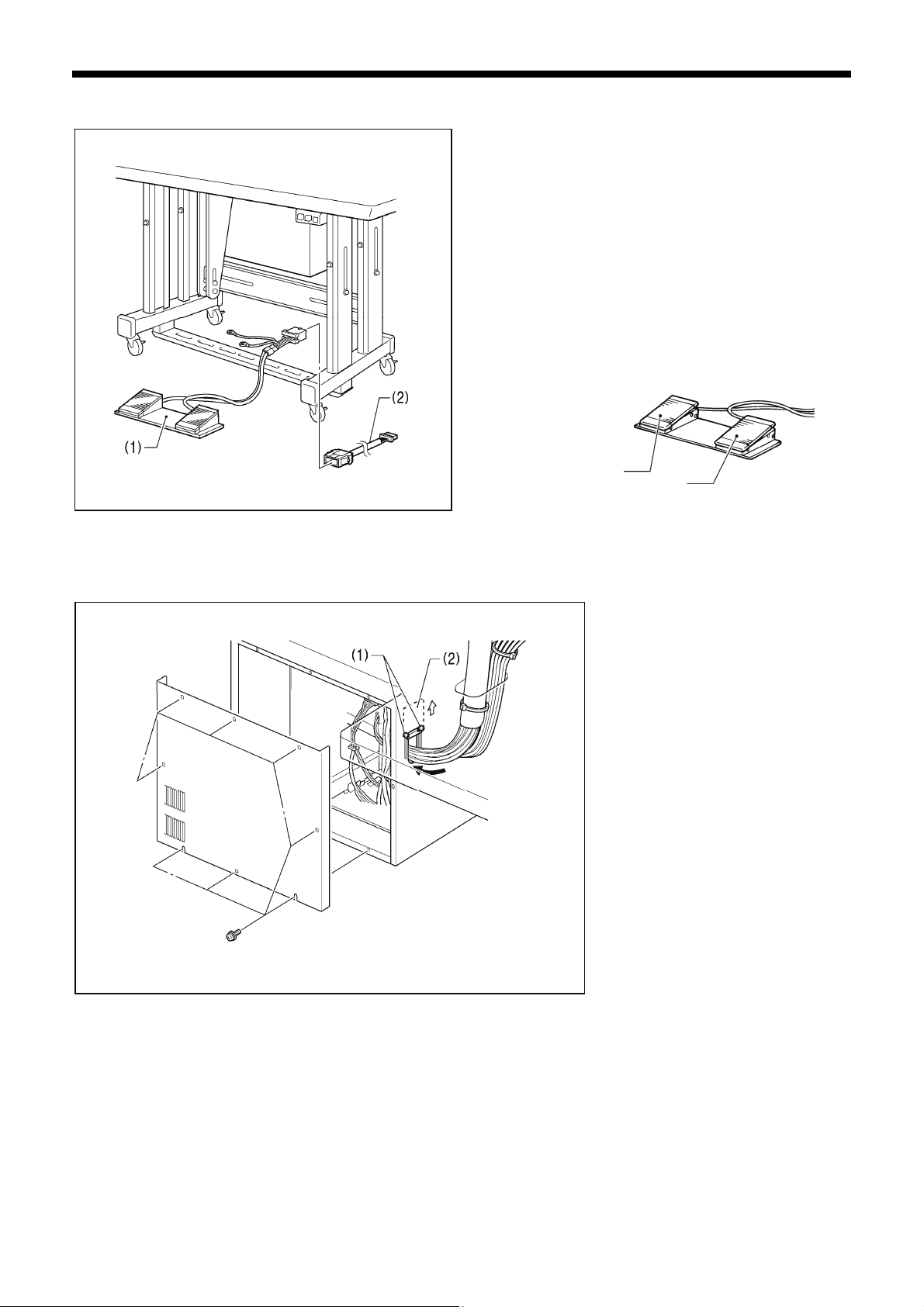
3-11. Installing the two-pedal foot switch
3530B
(1) Two-pedal foot switch
(2) Conversion harness
Connect the connector for the two-pedal foot switch (1) to the
conversion harness (2). Insert the conversion harness (2) into
the P15 (PEDAL) connector on the main P.C. board. (Refer to
"3-12. Connecting the cords".)
* Be sure to make the ground connection. (Refer to “3-13.
Connecting the ground wire”.)
<Two-pedal foot switch operating method>
When the work clamp switch (left) is depressed, the work clamp
is lowered, and when the start switch (right) is depressed, the
sewing machine starts sewing.
Work clamp switch (2-step)
Start switch
4923Q
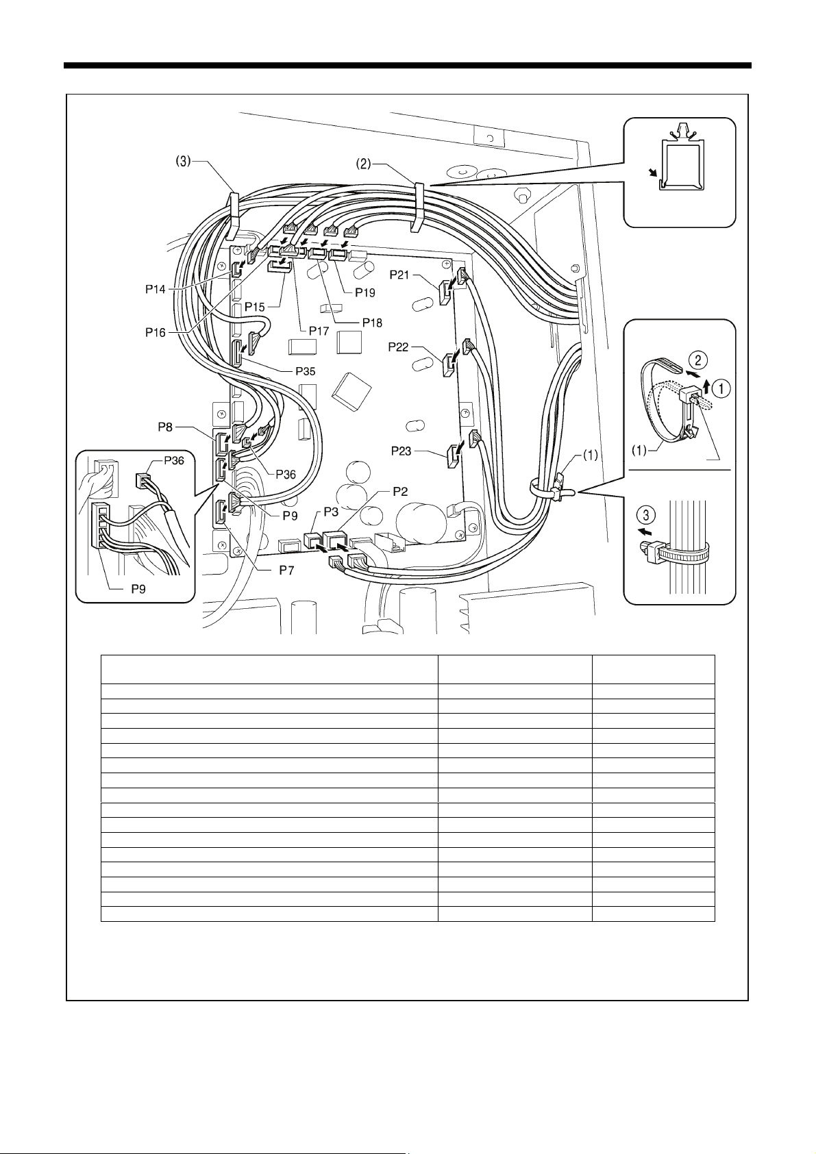
3-12. Connecting the cords
1. Remove the cover of the control box.
2. Loosen the two screws (1), and then
open the cord presser plate (2) in the
direction of the arrow.
3. Pass the bundle of cords from the
machine head through the hole in the
table, and then pass it through the
hole in the control box together with
the solenoid valve.
4. Securely connect the connectors as
indicated in the table.
(Refer to next page)
NOTE:
・ Check that the connector is facing
the correct way, and then insert it
firmly until it locks into place.
・ Secure the cables with cable ties
and cord clamps, while being careful
not to pull on the connector.
3568B
11
BAS-341H, BAS-342H
3. INSTALLATION
< Main P. C. board >
Lock the cord
clamp securely.
<Removal>
Press the tab.
<Securing>
3672B
X pulse motor encoder [5-pin] White P17 (X-ENC) (2)
Y pulse motor encoder [5-pin] Blue P18 (Y-ENC) (2)
Intermittent presser foot pulse motor encoder [5-pin] Black P19 (P-ENC) (2)
Machine head switch [3-pin] P14 (HEAD-SW) (2)
Conversion harness [7-pin] White P15 (PEDAL) (2)
Machine head memory [6-pin] P16 (HEAD-M) (2)
Thread trimmer solenoid [6-pin] P2 (SOL1) (1)
Digital tension solenoid / Tension release solenoid [4-pin] P3 (SOL2) (1)
X pulse motor [4-pin] White P21 (XPM) (1)
Y pulse motor [4-pin] Blue P22 (YPM) (1)
Work clamp pulse motor [4-pin] Black P23 (PPM) (1)
Home position sensor [12-pin] White P8 (SENSOR1) (2) (3)
STOP switch [6-pin] White P9 (HEAD) (2) (3)
Valve harness [12-pin] P35 (EX-OUT1) (2) (3)
Upper thread breakage detector [2-pin] White P36, P9(HEAD) (2) (3)
Fan [6-pin] P7 (SENSOR2) (2) (3)
Connectors
Connection location on
main P. C. board
Cord clamps /
cable ties
NOTE: Route the X, Y and work clamp pulse motor harnesses so that they do not touch the power supply P.C. board at
the bottom of the control box.
BAS-341H, BAS-342H
12
Loading...