


VDX 6710-54
Table of contents
 Loading...
53-1002338-03
5 August 2013
®
53-1002338-03
*53-1002338-03*
Brocade VDX 6710-54
QuickStart Guide
Supporting the VDX 6710-54
2 of 12 Brocade VDX 6710-54 QuickStart Guide
Publication Number: 53-1002338-03
Copyright © 2011-2013 Brocade Communications Systems, Inc. All Rights Reserved.
ADX, AnyIO, Brocade, Brocade Assurance, the B-wing symbol, DCX, Fabric OS, ICX, MLX, MyBrocade, OpenScript, VCS, VDX, and Vyatta are
registered trademarks, and HyperEdge, The Effortless Network, and The On-Demand Data Center are trademarks of Brocade Communications
Systems, Inc., in the United States and/or in other countries. Other brands, products, or service names mentioned may be trademarks of their
respective owners.
Notice: This document is for informational purposes only and does not set forth any warranty, expressed or implied, concerning any equipment,
equipment feature, or service offered or to be offered by Brocade. Brocade reserves the right to make changes to this document at any time,
without notice, and assumes no responsibility for its use. This informational document describes features that may not be currently available.
Contact a Brocade sales office for information on feature and product availability. Export of technical data contained in this document may
require an export license from the United States government.
The authors and Brocade Communications Systems, Inc. shall have no liability or responsibility to any person or entity with respect to any loss,
cost, liability, or damages arising from the information contained in this book or the computer programs that accompany it.
The product described by this document may contain “open source” software covered by the GNU General Public License or other open source
license agreements. To find out which open source software is included in Brocade products, view the licensing terms applicable to the open
source software, and obtain a copy of the programming source code, please visit
http://www.brocade.com/support/oscd.
Brocade Communications Systems, Incorporated
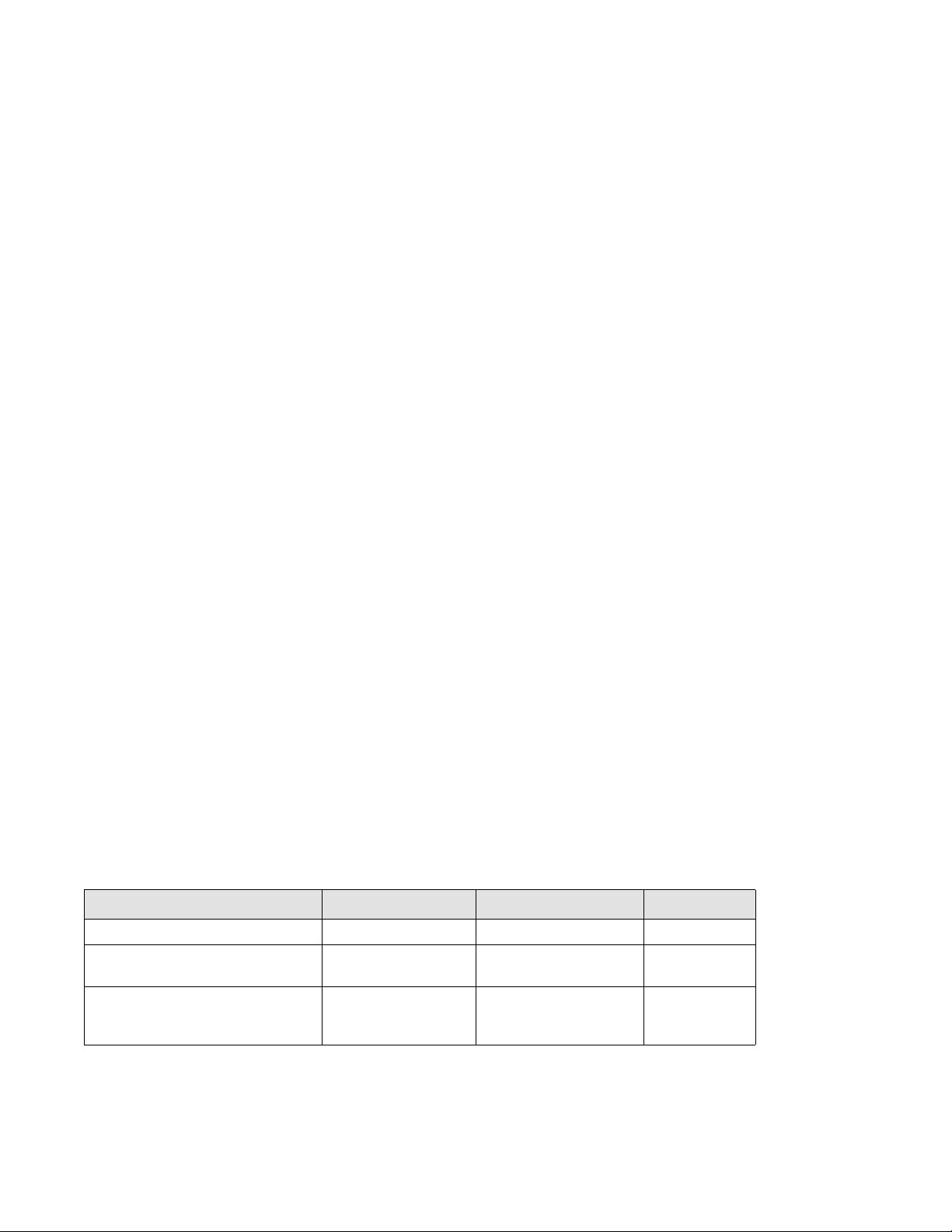
Document History
The following table lists all published versions of the Brocade VDX 6710-54 QuickStart Guide.
Corporate and Latin American Headquarters
Brocade Communications Systems, Inc.
130 Holger Way
San Jose, CA 95134
Tel: 1-408-333-8000
Fax: 1-408-333-8101
E-mail: info@brocade.com
Asia-Pacific Headquarters
Brocade Communications Systems China HK, Ltd.
No. 1 Guanghua Road
Chao Yang District
Units 2718 and 2818
Beijing 100020, China
Tel: +8610 6588 8888
Fax: +8610 6588 9999
E-mail: china-info@brocade.com
European Headquarters
Brocade Communications Switzerland Sàrl
Centre Swissair
Tour B - 4ème étage
29, Route de l'Aéroport
Case Postale 105
CH-1215 Genève 15
Switzerland
Tel: +41 22 799 5640
Fax: +41 22 799 5641
E-mail: emea-info@brocade.com
Asia-Pacific Headquarters
Brocade Communications Systems Co., Ltd. (Shenzhen WFOE)
Citic Plaza
No. 233 Tian He Road North
Unit 1308 – 13th Floor
Guangzhou, China
Tel: +8620 3891 2000
Fax: +8620 3891 2111
E-mail: china-info@brocade.com
Title Publication number Summary of changes Date
Brocade VDX 6710-54 QuickStart Guide 53-1002338-01 New document September 2011
Brocade VDX 6710-54 QuickStart Guide 53-1002338-02 Rack mount information was
updated.
August 2012
Brocade VDX 6710-54 QuickStart Guide 53-1002338-03 Updated Items Included with
USB device. Updated hub
connections.
August 2013

Brocade VDX 6710-54 QuickStart Guide 3 of 12
Publication Number: 53-1002338-03
Overview
This Quick Start guide is intended as an overview to help experienced installers unpack, install, and configure the
Brocade VDX 6710-54 quickly. For more detailed installation and configuration instructions, see the Brocade
Network OS Administrator’s Guide and the Brocade Network OS Command Reference Manual.
NOTE
Throughout this document, the Brocade VDX 6710 is referred to as the switch.
Items included with the Brocade VDX 6710-54
The following items are included with the standard shipment of a fully-configured Brocade VDX 6710-54. When you
open the Brocade VDX 6710-54 packaging, verify that the items are included in the package and that no damage
has occurred during shipping:
• The Brocade VDX 6710-54 switch
• One accessory kit, containing the following items:
- Serial cable with an RJ45 connector
- 6 ft. power cords (2)
- Rubber feet, required for setting up the switch as a standalone unit
- Brocade 2 GB USB memory device
- Brocade VDX 6710-54 QuickStart Guide (this publication)
Installation and safety considerations
You can install a Brocade VDX 6710-54 switch in the following ways:
• As a standalone unit on a flat surface.
• In an EIA four-post rack using a fixed-rail rack mount kit. The fixed-rail rack mount kit can be ordered from your
switch retailer.
• In a Telco rack using a flush mount rack kit. The flush mount rack kit for switches can be ordered from your
switch retailer.
Electrical considerations
To install and operate the switch successfully, ensure compliance with the following requirements:
• The primary outlet is correctly wired, protected by a circuit breaker, and grounded in accordance with local
electrical codes.
• The supply circuit, line fusing, and wire size are adequate, as specified by the electrical rating on the switch
nameplate.
• The power supply standards are met. Refer to Table 1 on page 4 for more information.

4 of 12 Brocade VDX 6710-54 QuickStart Guide
Publication Number: 53-1002338-03
.
Environmental considerations
For successful installation and operation of the switch, ensure that the following environmental requirements are
met:
• Because the Brocade VDX 6710-54 switch can be ordered with fans that move air either front to back or back to
front, be sure to orient your switch with the airflow pattern of any other devices in the rack. All equipment in the
rack should force air in the same direction to avoid intake of exhaust air.
• A maximum of 101.9 cubic meters/hour (60 cubic feet/minute) and a nominal flow of 74.8 cubic meters/hour
(44 cubic feet/minute) of airflow is available to the air intake vents.
• The ambient air temperature does not exceed 40° C (104° F) while the switch is operating.
Rack considerations
For successful installation and operation of the switch in a rack, ensure the following rack requirements are met:
• The rack must be a standard EIA cabinet.
• The rack space required is one rack unit (1U); 4.45 cm (1.75 in.) high and 48.3 cm (19 in.) wide.
• The equipment in the rack is grounded through a reliable branch circuit connection and maintains ground at all
times. Do not rely on a secondary connection to a branch circuit, such as a power strip.
• Airflow and temperature requirements are met on an ongoing basis, particularly if the switch is installed in a
closed or multirack assembly.
• The additional weight of the switch does not exceed the rack’s weight limits or unbalance the cabinet in any way.
• The rack is secured to ensure stability in case of unexpected movement, such as an earthquake.
Recommendations for cable management
The minimum radius to which a 50 micron cable can be bent under full tensile load is 5.1 cm (2 in.). For a cable
under no tensile load, that minimum is 3.0 cm (1.2 in.).
Cables can be organized and managed in a variety of ways; for example, use cable channels on the sides of the
cabinet or patch panels to reduce the potential for tangling the cables. The following list provides some
recommendations for cable management:
TABLE 1 System power specifications
Specification Value
Maximum output (per power supply) 250 watts, 12 VDC
AC input power draw Idle: 106 W
Maximum: 131 W
AC input voltage 85-264 VAC, nominal 100-240 VAC
AC input line frequency 47-63 Hz, nominal 50-60 Hz
AC inrush current Maximum of 50A @ 240 VAC for 10ms or less
Input line protection AC lines are fused
Loading...