


 Loading...
53-1003077-01
08 January 2014
Brocade FCX Series
Hardware Installation Guide
Supporting FastIron Software Release 08.0.10
© 2014, Brocade Communications Systems, Inc. All Rights Reserved.
Brocade, the B-wing symbol, Brocade Assurance, ADX, AnyIO, DCX, Fabric OS, FastIron, HyperEdge, ICX, MLX, MyBrocade, NetIron, OpenScript, VCS, VDX, and Vyatta are registered trademarks, and The Effortless Network and the On-Demand Data Center are trademarks of Brocade Communications Systems, Inc., in the United States and in other countries. Other brands and product names mentioned may be trademarks of others.
Notice: This document is for informational purposes only and does not set forth any warranty, expressed or implied, concerning any equipment, equipment feature, or service offered or to be offered by Brocade. Brocade reserves the right to make changes to this document at any time, without notice, and assumes no responsibility for its use. This informational document describes features that may not be currently available. Contact a Brocade sales office for information on feature and product availability. Export of technical data contained in this document may require an export license from the United States government.
The authors and Brocade Communications Systems, Inc. assume no liability or responsibility to any person or entity with respect to the accuracy of this document or any loss, cost, liability, or damages arising from the information contained herein or the computer programs that accompany it.
The product described by this document may contain open source software covered by the GNU General Public License or other open source license agreements. To find out which open source software is included in Brocade products, view the licensing terms applicable to the open source software, and obtain a copy of the programming source code, please visit http://www.brocade.com/support/oscd.

Contents
Preface..................................................................................................................................... |
5 |
Document conventions...................................................................................... |
5 |
Text formatting conventions.................................................................. |
5 |
Command syntax conventions.............................................................. |
5 |
Notes, cautions, and warnings.............................................................. |
6 |
Brocade resources............................................................................................ |
7 |
Getting technical help........................................................................................ |
7 |
Document feedback.......................................................................................... |
8 |
About This Document................................................................................................................ |
9 |
Introduction....................................................................................................... |
9 |
Supported Software.............................................................................. |
9 |
What’s new in this document ........................................................................... |
9 |
Product Overview.................................................................................................................... |
11 |
Hardware features........................................................................................... |
11 |
Control features................................................................................... |
15 |
Power supplies.................................................................................... |
31 |
Installing the FCX Switch......................................................................................................... |
33 |
Unpacking the device...................................................................................... |
33 |
Package contents................................................................................ |
33 |
General requirements......................................................................... |
33 |
Installation tasks.............................................................................................. |
34 |
Installation precautions................................................................................... |
35 |
General precautions............................................................................ |
35 |
Lifting precautions............................................................................... |
35 |
Power precautions.............................................................................. |
35 |
Preparing the installation site.......................................................................... |
36 |
Cabling infrastructure.......................................................................... |
36 |
Installation location.............................................................................. |
36 |
Installing the device............................................................................. |
37 |
Desktop installation............................................................................. |
37 |
Rack mount installation....................................................................... |
38 |
Connecting devices in a traditional stack........................................................ |
41 |
Stacking ports..................................................................................... |
41 |
Stacking configuration requirements................................................... |
44 |
Stacking cables................................................................................... |
44 |
Stack size............................................................................................ |
44 |
Stacking topologies............................................................................. |
44 |
Extended distance stacking................................................................ |
48 |
Powering on the system.................................................................................. |
48 |
Attaching a PC or terminal.............................................................................. |
49 |
Wiring map for serial cable.................................................................. |
50 |
Installing and replacing a power supply unit................................................... |
50 |
Installing or replacing fan trays....................................................................... |
52 |
Installing an optional module .......................................................................... |
53 |
Brocade FCX Series Hardware Installation Guide |
1 |
53-1003077-01 |
|
Optional 2-port 10 Gbps SFP+ uplink module.................................. |
55 |
Checking Network Devices and Testing Connectivity............................................................... |
59 |
Assigning permanent passwords.................................................................. |
59 |
Setting passwords............................................................................. |
60 |
Recovering from a lost password...................................................... |
60 |
Configuring IP addresses.............................................................................. |
61 |
Devices running Layer 2 software..................................................... |
61 |
Devices running Layer 3 software..................................................... |
62 |
Connecting network devices............................................................. |
65 |
Connectors........................................................................................ |
65 |
Cable specifications.......................................................................... |
65 |
Connecting to Ethernet or fast Ethernet hubs................................... |
65 |
Connecting to workstations, servers, or routers................................ |
66 |
Connecting a network device to a fiber port...................................... |
67 |
Testing connectivity....................................................................................... |
71 |
Pinging an IP address....................................................................... |
71 |
Observing LEDs................................................................................ |
71 |
Tracing a route.................................................................................. |
73 |
Troubleshooting network connections.......................................................... |
74 |
Using Virtual Cable Testing to diagnose a cable.............................. |
74 |
Digital optical monitoring................................................................... |
75 |
Managing the FCX Hardware................................................................................................. |
77 |
Managing temperature settings.................................................................... |
77 |
Using the temperature sensor........................................................... |
77 |
Removing MAC address entries....................................................... |
80 |
Displaying FCX CPU usage.......................................................................... |
81 |
Hardware maintenance schedule................................................................. |
81 |
Replacing a copper or fiber optic module..................................................... |
81 |
Removing a copper or fiber optic module......................................... |
81 |
Cabling a fiber optic module.............................................................. |
83 |
Cleaning the fiber optic connectors................................................... |
83 |
Hardware Specifications....................................................................................................... |
85 |
Hardware specifications................................................................................ |
85 |
Physical dimensions and weight....................................................... |
85 |
Environmental considerations........................................................... |
85 |
Cooling system and fans................................................................... |
86 |
Pinouts and signalling....................................................................... |
89 |
Cable specifications.......................................................................... |
91 |
Power cords...................................................................................... |
92 |
AC power supply specifications........................................................ |
93 |
Troubleshooting ................................................................................................................... |
95 |
Diagnosing switch indicators ........................................................................ |
95 |
Power and cooling problems............................................................. |
95 |
Installation......................................................................................... |
95 |
In-band access.................................................................................. |
95 |
Regulatory Statements.......................................................................................................... |
97 |
USA (FCC CFR 47 Part 15 Warning)............................................................ |
97 |
2 |
Brocade FCX Series Hardware Installation Guide |
|
53-1003077-01 |
Industry Canada statement............................................................................. |
97 |
Europe and Australia (CISPR 22 Class A Warning)....................................... |
98 |
Germany (Noise Warning).............................................................................. |
98 |
Japan (VCCI).................................................................................................. |
98 |
Japan power cord............................................................................................ |
98 |
Korea............................................................................................................... |
99 |
China............................................................................................................. |
100 |
BSMI statement (Taiwan).............................................................................. |
100 |
Regulatory compliance.................................................................................. |
101 |
Cautions and Danger Notices................................................................................................ |
103 |
Cautions........................................................................................................ |
103 |
Danger notices.............................................................................................. |
107 |
Brocade FCX Series Hardware Installation Guide |
3 |
53-1003077-01 |
|
4 |
Brocade FCX Series Hardware Installation Guide |
|
53-1003077-01 |

Preface
● Document conventions...................................................................................................... |
5 |
● Brocade resources............................................................................................................ |
7 |
● Getting technical help........................................................................................................ |
7 |
● Document feedback.......................................................................................................... |
8 |
Document conventions
The document conventions describe text formatting conventions, command syntax conventions, and important notice formats used in Brocade technical documentation.
Text formatting conventions
Text formatting conventions such as boldface, italic, or Courier font may be used in the flow of the text to highlight specific words or phrases.
Format
bold text
italic text
Courier font
Description
Identifies command names
Identifies keywords and operands
Identifies the names of user-manipulated GUI elements Identifies text to enter at the GUI
Identifies emphasis
Identifies variables and modifiers
Identifies paths and Internet addresses
Identifies document titles
Identifies CLI output
Identifies command syntax examples
Command syntax conventions
Bold and italic text identify command syntax components. Delimiters and operators define groupings of parameters and their logical relationships.
Convention |
Description |
bold text |
Identifies command names, keywords, and command options. |
italic text |
Identifies a variable. |
Brocade FCX Series Hardware Installation Guide |
5 |
53-1003077-01 |
|

Notes, cautions, and warnings
Convention
value
[ ]
{x | y | z }
x | y
< >
...
\
Description
In Fibre Channel products, a fixed value provided as input to a command option is printed in plain text, for example, --show WWN.
Syntax components displayed within square brackets are optional.
Default responses to system prompts are enclosed in square brackets.
A choice of required parameters is enclosed in curly brackets separated by vertical bars. You must select one of the options.
In Fibre Channel products, square brackets may be used instead for this purpose.
A vertical bar separates mutually exclusive elements.
Nonprinting characters, for example, passwords, are enclosed in angle brackets.
Repeat the previous element, for example, member[member...].
Indicates a “soft” line break in command examples. If a backslash separates two lines of a command input, enter the entire command at the prompt without the backslash.
Notes, cautions, and warnings
Notes, cautions, and warning statements may be used in this document. They are listed in the order of increasing severity of potential hazards.
NOTE
A note provides a tip, guidance, or advice, emphasizes important information, or provides a reference to related information.
ATTENTION
An Attention statement indicates potential damage to hardware or data.
CAUTION
A Caution statement alerts you to situations that can be potentially hazardous to you or cause damage to hardware, firmware, software, or data.
DANGER
A Danger statement indicates conditions or situations that can be potentially lethal or extremely hazardous to you. Safety labels are also attached directly to products to warn of these conditions or situations.
6 |
Brocade FCX Series Hardware Installation Guide |
|
53-1003077-01 |

Brocade resources
Brocade resources
Visit the Brocade website to locate related documentation for your product and additional Brocade resources.
You can download additional publications supporting your product at www.brocade.com.
•Adapter documentation is available on the Downloads and Documentation for Brocade Adapters page. Select your platform and scroll down to the Documentation section.
•For all other products, select the Brocade Products tab to locate your product, then click the Brocade product name or image to open the individual product page. The user manuals are available in the resources module at the bottom of the page under the Documentation category.
To get up-to-the-minute information on Brocade products and resources, go to MyBrocade. You can register at no cost to obtain a user ID and password.
Release notes are available on MyBrocade under Product Downloads.
White papers, online demonstrations, and data sheets are available through the Brocade website.
Getting technical help
You can contact Brocade Support 24x7 online, by telephone, or by e-mail.
For product support information and the latest information on contacting the Technical Assistance Center, go to http://www.brocade.com/services-support/index.html.
Use one of the following methods to contact the Brocade Technical Assistance Center.
Online |
Telephone |
|
|
|
|
Preferred method of contact for non- |
Required for Sev 1-Critical and Sev |
||
urgent issues: |
2-High issues: |
||
• |
My Cases through MyBrocade |
• |
Continental US: |
• |
Software downloads and |
|
1-800-752-8061 |
|
licensing tools |
• |
Europe, Middle East, Africa, |
• |
Knowledge Base |
|
and Asia Pacific: +800-AT |
|
|
|
FIBREE (+800 28 34 27 33) |
|
|
• |
For areas unable to access toll |
|
|
|
free number: +1-408-333-6061 |
|
|
• |
Toll-free numbers are available |
|
|
|
in many countries. |
support@brocade.com
Please include:
•Problem summary
•Serial number
•Installation details
•Environment description
Brocade FCX Series Hardware Installation Guide |
7 |
53-1003077-01 |
|
Document feedback
Document feedback
To send feedback and report errors in the documentation you can use the feedback form posted with the document or you can e-mail the documentation team.
Quality is our first concern at Brocade and we have made every effort to ensure the accuracy and completeness of this document. However, if you find an error or an omission, or you think that a topic needs further development, we want to hear from you. You can provide feedback in two ways:
•Through the online feedback form in the HTML documents posted on www.brocade.com.
•By sending your feedback to documentation@brocade.com.
Provide the publication title, part number, and as much detail as possible, including the topic heading and page number if applicable, as well as your suggestions for improvement.
8 |
Brocade FCX Series Hardware Installation Guide |
|
53-1003077-01 |
About This Document
● Introduction....................................................................................................................... |
9 |
● What’s new in this document ........................................................................................... |
9 |
Introduction
This guide includes procedures for installing and maintaining the hardware. The hardware procedures show how to install or assemble the various hardware components with the necessary precautions, warnings, and regulatory statements. This guide also describes the required device specifications for running the hardware.
Supported Software
For information about the features supported on a hardware platform, refer to the appropriate configuration guide.
What’s new in this document
This document is enhanced to support the current FastIron release 08.0.10.
Brocade FCX Series Hardware Installation Guide |
9 |
53-1003077-01 |
|
What’s new in this document
10 |
Brocade FCX Series Hardware Installation Guide |
|
53-1003077-01 |

Product Overview
● Hardware features........................................................................................................... |
11 |
Hardware features
The following hardware platforms are supported by this release of this guide:
•The Brocade FCX 624S stackable switch has twenty 10/100/1000 Mbps ports plus four Combo ports, which include four 10/100/1000 Mbps RJ45 ports and four 100/1000 Mbps SFP ports. The switch has two management interfaces, a DB9 serial port (Console) on the front panel and an RJ45 port (Out-of-band Management Interface) on the rear panel. Two rear-panel power supply receptacles allow for up to two power supply units. Two dedicated 16 GbE CX4 ports on the rear panel allow stacking for up to eight units. The front panel also has a module slot for an optional two-port 10 Gbps XFP module.
•The Brocade FCX 648S stackable switch has forty four 10/100/1000 Mbps RJ45 ports plus four Combo ports, which include four 10/100/1000 Mbps RJ45 ports and four 100/1000 Mbps SFP ports. The switch has two management interfaces, a DB9 serial port (Console) on the front panel and an RJ45 port (Out-of-band Management Interface) on the rear panel. Two rear-panel power supply receptacles allow for up to two power supply units. Two dedicated 16 Gbps Ethernet CX4 ports on the rear panel allow stacking for up to eight units. The front panel also has a module slot for an optional two-port 10 Gbps Ethernet XFP module.
•The Brocade FCX 624S-F stackable switch has two management interfaces, a DB9 serial port (Console) on the front panel and an RJ45 port (Out-of-band Management Interface) on the rear panel. Two rear-panel power supply receptacles allow for up to two power supply units. Two dedicated 16 Gbps Ethernet CX4 ports on the rear panel allow stacking for up to eight units. The front panel also has a module slot for an optional two-port 10 Gbps Ethernet XFP module.
•The Brocade FCX 624S-HPOE stackable switch has twenty 100/1000 Mbps ports plus four Combo ports, which include four 10/100/1000 Mbps RJ45 ports and four 100/1000 Mbps SFP ports. The switch has two management interfaces, a DB9 serial port (Console) on the front panel and an RJ45 port (Out-of-band Management Interface) on the rear panel. Two rear-panel power supply receptacles allow for up to two power supply units. Two dedicated 16 Gbps Ethernet CX4 ports on the rear panel allow stacking for up to eight units. The front panel also has a module slot for an optional two-port 10 Gbps Ethernet XFP module.
•The Brocade FCX 648S-HPOE has is a stackable switch with forty four 10/100/1000 Mbps ports plus four Combo ports, which include four 10/100/1000 Mbps RJ45 ports and four 100/1000 Mbps SFP ports. The switch has two management interfaces, a DB9 serial port (Console) on the front panel and an RJ45 port (Out-of-band Management Interface) on the rear panel. Two rear-panel power supply receptacles allow for up to two power supply units. Two dedicated 16 Gbps Ethernet CX4 ports on the rear panel allow stacking for up to eight units. The front panel also has a module slot for an optional two-port 10 Gbps Ethernet XFP module.
•The Brocade FCX 624-E switch has twenty four 10/100/1000 Mbps ports. The device has two management interfaces on the front panel, a DB9 serial port (Console) and an RJ45 port (Out-of- band Management Interface). The front panel has a slot for an optional four-port 1GbE SFP module (works as Combo port) or four-port 10 Gbps SFP+ module. On the rear panel a removable fan tray provides a cooling airflow from the front to the rear of the device. Two rear-panel power supply receptacles accommodate up to two power supply units that also support a front-to-rear cooling airflow.
Brocade FCX Series Hardware Installation Guide |
11 |
53-1003077-01 |
|

Product Overview
•The Brocade FCX 624-I switch has twenty four 10/100/1000 Mbps ports. The device has two management interfaces on the front panel, a serial port (Console) and an RJ45 port (Out-of-band Management Interface). The front panel has a slot for an optional four-port 1GbE SFP module (works as Combo port) or four-port 10 Gbps SFP+ module. On the rear panel a removable fan tray provides a cooling airflow from the rear to the front of the device. Two rear-panel power supply receptacles accommodate up to two power supply units that also support a rear-to-front cooling airflow.
•The Brocade FCX 648-E switch has forty four 10/100/1000 Mbps ports. The device has two management interfaces on the front panel, a serial port (Console) and an RJ45 port (Out-of-band Management Interface). The front panel has a slot for an optional four-port 1GbE SFP module (works as Combo port) or four-port 10 Gbps SFP+ module. On the rear panel a removable fan tray provides a cooling airflow from the front to the rear of the device. Two rear-panel power supply receptacles accommodate up to two power supply units that also support a front-to-rear cooling airflow..
•The Brocade FCX 648-I switch has forty four 10/100/1000 Mbps ports. The device has two management interfaces on the front panel, a serial port (Console) and an RJ45 port (Out-of-band Management Interface). The front panel has a slot for an optional four-port 1GbE SFP module, (works as Combo port) or four-port 10 Gbps SFP+ module. On the rear panel a removable fan tray provides a cooling airflow from the rear to the front of the device. Two rear-panel power supply receptacles accommodate up to two power supply units that also support a rear-to-front cooling airflow.
NOTE
All FCX models support Layer 2 and Enterprise Layer 3 protocols (RIP, OSPF, PIM). FCX models can be ordered from the factory as -ADV (Advanded Layer 3) models, which adds support for the Layer 3 BGP routing protocol and GRE.
The following sections describe the physical characteristics of the FastIron CX models. For more details about physical dimensions, power supply specifications, and pinouts, refer to the "Hardware Specifications" section.
The following figures show the front panels of the FastIron CX models. For more information about Combo ports, see Network interfaces for Brocade FCX 624-E, FCX 624-I, FCX 648-E, and FCX 648-I
12 |
Brocade FCX Series Hardware Installation Guide |
|
53-1003077-01 |

Product Overview
on page 15. For more information about control features in general, see Control features on page 15.
FIGURE 1 Brocade FCX 624S front panel
FIGURE 2 Brocade FCX 648S front panel
FIGURE 3 Brocade FCX 624S-F front panel
FIGURE 4 Brocade FCX 624S-HPOE front panel
FIGURE 5 Brocade FCX 648S-HPOE front panel
FIGURE 6 Brocade FCX 648S-HPOE rear panel
FIGURE 7 Brocade FCX 624-E front panel
FIGURE 8 Brocade FCX 624-I front panel
Brocade FCX Series Hardware Installation Guide |
13 |
53-1003077-01 |
|

Product Overview
FIGURE 9 Brocade FCX 648-E front panel
FIGURE 10 Brocade FCX 648-I front panel
FIGURE 11 Brocade FCX 624-E, FCX 624-I, FCX 648-E, and FCX 648-I rear panels
CAUTION
For the Brocade FCX 624-E, FCX 624-I, FCX 648-E, and FCX 648-I devices, be sure that the airflow direction of the power supply unit matches that of the installed resiliant quad-fan fan tray. The power supplies and fan trays are clearly labeled with either a green arrow with an "E", or an orange arrow with an "I".
Device |
Label on required power supply |
Label on |
|
|
required fan |
|
|
tray |
Brocade FCX 624-E
and Brocade FCX 648-
E
14 |
Brocade FCX Series Hardware Installation Guide |
|
53-1003077-01 |

Control features
Device |
Label on required power supply |
Label on |
|
|
required fan |
|
|
tray |
|
|
|
Brocade FCX 624-I and |
|
|
Brocade FCX 648-I |
|
|
Control features
Each device front panel includes the following control features:
•Serial management interface (the DB9 port labeled Console )
•Out-of-band RJ45 management Interface
Serial management interface (DB9 Console port)
The serial management interface allows you to configure and manage the device using a third-party terminal emulation application on a directly-connected PC. A straight-through EIA or TIA DB9 serial cable (M or F) ships with the device. The serial management interface (the DB9 Console port) is located in the left corner of the front panel.
Out-of-band RJ45 management interface
The out-of-band RJ45 management interface enables you to configure and manage the device using a third-party terminal emulation application on a directly-connected PC.
Network interfaces for Brocade FCX 624S, FCX 648S, FCX 624S-F, FCX 624S-HPOE, and FCX 648S-HPOE
FCX devices contain the following interfaces:
•10/100/1000 Mbps ports with RJ45 copper connectors
•100/1000 Mbps ports with mini-GBIC slots for SFP MSA-compliant fiber transceivers
•Optional 2-port 10Gbps Ethernet XFP module
•CX4 stacking ports
NOTE
Brocade recommends that you refer to Cable specifications on page 65 before connecting a cable to any of the ports.
Network interfaces for Brocade FCX 624-E, FCX 624-I, FCX 648-E, and FCX 648-I
FastIron CX devices contain the following interfaces:
Brocade FCX Series Hardware Installation Guide |
15 |
53-1003077-01 |
|

Product Overview
•10/100/1000 ports with RJ45 copper connectors
•100/1000 ports with mini-GBIC slots for MSA-compliant SFP transceivers
•Optional 4-port 1Gbps Ethernet SFP module
•Optional 4-port 10Gbps Ethernet SFP+ module
NOTE
Brocade recommends that you refer to Cable specifications on page 65 before connecting a cable to any of the ports.
FastIron CX 10/100/1000 BASE-T ports
All FastIron CX devices except for the fiber models contain 24 or 48 RJ45 ports that operate at 10 Mbps or 100 Mbps, half or full duplex, or at 1000 Mbps, full duplex. FCX fiber models contain 24 SFP ports. Because all ports support automatic MDI or MDI-X operation, you can use straight-through cables for all network connections to PCs or servers, or to other switches or hubs. In addition, it is ideal and preferred to use straight-through cable for switch-to-switch connections.
Each of these ports supports auto-negotiation, so the optimum transmission mode (half or full duplex), and the data rate (10, 100, or 1000 Mbps) can be selected automatically. If a device connected to one of these ports does not support auto-negotiation, the communication mode of the port can be configured manually.
Combination ports
FCX devices contain four combination ports, which are four Small Form Factor Pluggable (SFP) network interfaces (1F~4F) that are shared with four of the RJ45 ports (ports 1~4). In the default configuration, if an SFP transceiver is installed in a slot and has a valid link on its port, the associated RJ45 port is disabled and cannot be used. The switch can also be configured to force the use of a combination RJ45 port or SFP slot, as required.
NOTE
Brocade FCX 624-E, FCX 624-I, FCX 648-E, and FCX 648-I devices do not ship with SFP ports. You must install the optional SFP module for SFP support.
Slot locations
There are three slot locations on Brocade FCX Series devices: slots 3 and 1 on the front panel and slot 2 on the rear panel.
FIGURE 12 Slot locations on the front panel of Brocade FCX Series devices
16 |
Brocade FCX Series Hardware Installation Guide |
|
53-1003077-01 |

Product Overview
1.Slot 3
2.Slot 1
FIGURE 13 Slot location on the rear panel of Brocade FCX Series devices
1.Slot 2 (default stacking ports)
Slot designations
The slot designations for FCX models:
TABLE 1 Stack unit slots for FCX stackable devices
Device |
Slot 1 |
Slot 2 |
Slot 3 |
Brocade FCX 624S |
20 10/100/1000 Mbps ports plus 4 |
|
Combo ports (RJ45 ports 1-4, or SFP |
|
ports 1F-4F) |
2-port 16 Gbps CX4 |
2-port 10 Gbps |
stacking module on rear |
XFP module |
panel |
|
Brocade FCX 648S |
44 20 10/100/1000 Mbps ports plus 4 |
|
Combo ports (RJ45 ports 1-4, or SFP |
|
ports 1F-4F) |
2-port 16 Gbps CX4 |
2-port 10 Gbps |
stacking module on rear |
XFP module |
panel |
|
Brocade FCX 624S-F |
20 100/1000 Mbps SFP ports plus 4 |
|
Combo ports 10/100/1000 Mbps RJ45 |
|
on front panel |
2-port 16 Gbps CX4 |
2-port 10 Gbps |
stacking module on rear |
XFP module |
panel |
|
Brocade FCX 624-E and Brocade FCX 624-I devices with optional 4-port 1 Gbps SFP module
20 10/100/1000 Mbps RJ45 ports, plus N/A |
N/A |
4-port 1 Gbps SFP module (optional |
|
module) combined with the first four |
|
10/100/1000 Mbps RJ45 copper ports |
|
(acting as a Combo port). |
|
Brocade FCX 648-E and Brocade FCX 648-I devices with optional 4-port 1 Gbps SFP module
44 10/100/1000 Mbps RJ45 ports, plus N/A |
N/A |
4-port 1 Gbps SFP module (optional) |
|
combined with the first four |
|
10/100/1000 Mbps RJ45 copper ports |
|
(acting as a Combo port). |
|
Brocade FCX 624-E and |
24 10/100/1000 Mbps RJ45 ports |
4-port 10 Gbps SFP+ |
N/A |
Brocade FCX 624-I devices |
|
module on front panel |
|
with optional 4-port 10 Gbps |
|
(optional module) |
|
SFP+ module |
|
|
|
|
|
|
|
|
|
|
|
Brocade FCX Series Hardware Installation Guide |
17 |
53-1003077-01 |
|

SFP interfaces
TABLE 1 Stack unit slots for FCX stackable devices (Continued)
Device |
Slot 1 |
Slot 2 |
Slot 3 |
|
|
|
|
Brocade FCX 648-E and |
48 10/100/1000 Mbps RJ45 ports |
4-port 10 Gbps SFP+ |
N/A |
Brocade FCX 648-I devices |
|
module on front panel |
|
with optional 4r-port 10 Gbps |
|
(optional module) |
|
SFP+ module |
|
|
|
|
|
|
|
|
|
|
|
SFP interfaces
This section describes the network interfaces supported on FCX devices. For information about supported SFP and SFP+ transceivers, refer to the following Brocade website:
http://www.brocade.com/downloads/documents/data_sheets/product_data_sheets/Optics_DS.pdf
TABLE 2 SFP network interfaces
Interface |
Show Media Description |
|
|
1000Base-BX-D |
M-GBXD |
|
|
1000Base-BX-U |
M-GBXU |
|
|
1000Base-LHA |
M-LHA |
|
|
1000Base-LHB |
M-LHB |
|
|
1000Base-LX |
M-LX |
|
|
1000Base-LH |
M-LH |
|
|
1000Base-SX |
M-SX |
|
|
1000Base-T |
C |
|
|
100Base-T |
C** |
|
|
10Base-T |
C** |
|
|
100Base-FX |
M-FX |
|
|
Optional two-port 10 Gbps XFP uplink module
The Brocade FCX 624S, FCX 648S, FCX 624S-F, FCX 624S-HPOE, and FCX 648S-HPOE devices include a slot on the front panel for a two-port 10 Gbps XFP uplink module. This module operates at 10 Gbps full duplex.
18 |
Brocade FCX Series Hardware Installation Guide |
|
53-1003077-01 |
Optional 4x1G SFP+ and 4x10G SFP+ modules
NOTE
The 10 Gbps XFP module is not hot-swappable.
FIGURE 14 Two-port 10 Gbps XFP module
TABLE 3 Two-port 10 Gbps XFP module port status LEDs
LED |
Condition |
Status |
|
|
|
Link or Act LED (Link or |
On or flashing Green |
Port has a valid link at 10 Gbps. Flashing |
Activity) |
|
indicates activity. |
|
|
|
|
Off |
The link is down. |
|
|
|
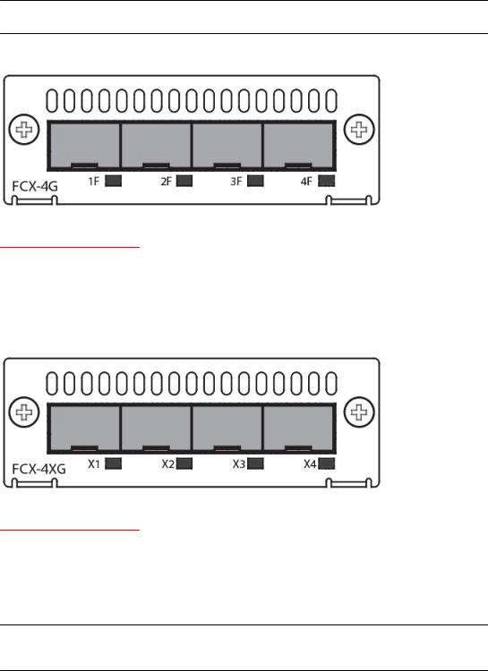
Optional 4x1G SFP+ and 4x10G SFP+ modules
The Brocade FCX 624-E, FCX 624-I, FCX 648-E, and FCX 648-I devices include a slot on the front panel for a four-port 1 Gbps SFP module, or a four-port 10 Gbps SFP+ module. The 1 Gbps SFP module operates at 1 Gbps full duplex, and the 10 Gbps SFP+ module operates at 10 Gbps full duplex.
FCX-I and FCX-E devices can be used in a homogeneous stack by installing the optional 4-port 10 Gbps SFP+ module, and connecting devices using standard duplex LC cables. These devices cannot be combined in a stack with non-FCX devices. For detailed information about how to configure FCX devices in a homogeneous stack, see the FastIron Ethernet Switch Stacking Configuration Guide .
Brocade FCX Series Hardware Installation Guide |
19 |
53-1003077-01 |
|
Product Overview
NOTE
The 1 Gbps SFP and 10 Gbps SFP+ modules are not hot-swappable.
FIGURE 15 Four-port 1 Gbps SFP module
TABLE 4 Four-port 1 Gbps SFP module status LEDs
LED |
Condition |
Status |
|
|
|
Link or Act LED (Link or |
On or flashing Green |
Port has a valid link at 1 Gbps. Flashing |
Activity) |
|
indicates activity. |
|
|
|
|
Off |
The link is down. |
|
|
|
FIGURE 16 Four-port 10 Gbps SFP+ module
TABLE 5 Four-port 10 Gbps SFP+ module status LEDs
LED |
Condition |
Status |
|
|
|
Link or Act LED (Link or |
On or flashing Green |
Port has a valid link at 10 Gbps. Flashing |
Activity) |
|
indicates activity. |
|
|
|
|
Off |
The link is down. |
|
|
|
NOTE
The two left ports on the SFP+ module do not pass regular Ethernet traffic by default. The stack disable CLI command must be configured on these two ports in order for them to pass regular traffic.
20 |
Brocade FCX Series Hardware Installation Guide |
|
53-1003077-01 |

16/10 Gbps Ethernet CX4 stacking module
16/10 Gbps Ethernet CX4 stacking module
The Brocade FCX 624S, FCX 648S, FCX 624S-F, FCX 624S-HPOE, and FCX 648S-HPOE devices include two 16/10 Gbps Ethernet CX4 ports on the rear panel (the stacking ports). The device can perform data transmission directly through copper links of up to 3 meters.
The Up Link and Down Link LEDs on the front panel indicate operational status. If the Up Link or Down Link LED is on, the port is connected. If the Up Link or Down Link LED is off, no connection exists, or the link is down.
Cable specifications for CX4 stacking ports
The following cable specifications apply to the CX4 stacking ports:
•Support for 802.3ak or 10 Gbps Ethernet CX4 standard and 16 Gbps inter-unit stacking (up to 8 units in a stack)
•Support for cables up to 3 meters in length
•Requires latch-style receptacle or SFF-8470 plug
NOTE
Brocade FCX 624-E, FCX 624-I, FCX 648-E, and FCX 648-I devices can be added to a stack using the first two ports on a four-port 10 Gbps SFP+ module (optional) using standard duplex LC cables.
Optional 2-port 10 Gbps SFP+ uplink module
Feature description for the 2-port 10 Gbps SFP+ module including modified CLI examples
The following Brocade FCX devices include a slot on the front panel for a two-port 10 Gbps SPF+ uplink module. This module operates at 10 Gbps full duplex.
•Brocade FCX 624S
•Brocade FCX 648S
•Brocade FCX 624S-F
•Brocade FCX 624S-HPOE
•Brocade FCX 648S-HPOE
The 2-port 10 Gbps SPF+ uplink module can replace the 2-port XFP module in the fixed slot 3. Port mapping is the same as for the 2x10 XFP with slot 3 and port 1 or 2, for example, 1/3/1 and 1/3/2. Stacking is supported using the stack default-port command with the 1/3/1 and 1/3/2 options.
The module is named FCX-2SFPP 2-port 10G Module (2-SFP+) in configuration and output.
NOTE
Reload the device whenever you install or replace the module because the 2x10 SFP+ module is not hot swappable.
Brocade FCX Series Hardware Installation Guide |
21 |
53-1003077-01 |
|

Product Overview
CAUTION
Power-down your device before you install or replace a module for safety purposes and to avoid instability due to a delay in power cycling.
FIGURE 17 Two-port 10 Gbps SFP+ module
TABLE 6 10 Gbps SFP+ module port status LEDs
LED |
Condition |
Status |
|
|
|
Link or Act LED (Link or |
On or flashing green |
Port has a valid link at 10 Gbps. |
Activity |
|
Flashing indicates activity. |
|
|
|
|
Off |
The port is down. |
|
|
|
22 |
Brocade FCX Series Hardware Installation Guide |
|
53-1003077-01 |
Product Overview
Modified CLI examples for the 2-port 10 Gbps SFP+ module
The following sample output from the show module command displays an entry for the 2-port 10G SFP+ module.
device# show module |
Status Ports Starting MAC |
|||
U1:M1 |
Module |
|||
FCX-48GS POE 48-port Management Module |
OK |
48 |
0024.38c9.4d00 |
|
U1:M2 |
FCX-2XGC 2-port 16G Module (2-CX4) |
OK |
2 |
0024.38c9.4d31 |
U1:M3 |
FCX-2SFPP 2-port 10G Module (2-SFP+) |
OK |
2 |
0024.38c9.4d33 |
The following sample output from the show version command shows that the 2- port 10G SFP+ module is in slot 3.
device# show version
Copyright (c) 1996-2011 Brocade Communications Systems, Inc.
UNIT 1: compiled on Oct 18 2012 at 16:01:04 labeled as FCXS07300b1 (5373912 bytes) from Primary FCXS07300b1.bin
SW: Version 07.3.00b1T7f1
Boot-Monitor Image size = 370663, Version:07.3.00T7f5 (grz07300b1) HW: Stackable FCX648S-HPOE-PREM (PROM-TYPE FCX-ADV-U)
==========================================================================
UNIT 1: SL 1: FCX-48GS POE |
48-port Management Module |
|
Serial |
#: BCYXXXXXXXX |
|
License: BASE_SOFT_PACKAGE (LID: deaHHJIhFNb) |
||
P-ENGINE |
0: type |
DB90, rev 01 |
P-ENGINE |
1: type |
DB90, rev 01 |
PROM-TYPE: FCX-ADV-U
==========================================================================
UNIT 1: SL 2: FCX-2XGC 2-port 16G Module (2-CX4)
==========================================================================
UNIT 1: SL 3: FCX-2SFPP 2-port 10G Module (2-SFP+)
==========================================================================
800 MHz Power PC processor 8544E (version 0021/0022) 400 MHz bus 65536 KB flash memory
256 MB DRAM
STACKID 1 system uptime is 2 days 10 minutes 24 seconds The system : started=warm start reloaded=by "reload"
The following is sample output of the show running-config command.
device# show running-config
!
Startup-config data location is flash memory
!
Startup configuration:
!
ver 07.3.00a001T7f1
!
stack unit 1
module 1 |
fcx-48-poe-port-management-module |
|
module |
2 |
fcx-cx4-2-port-16g-module |
module |
3 |
fcx-sfpp-2-port-10g-module |
!
The following is sample output of the show media and show optic commands with some configuration.
device# show media |
|
1/1/3:C |
1/1/4:C |
1/1/5:C |
1/1/6:C |
1/1/7:C |
1/1/8:C |
|
1/1/1:C |
1/1/2:C |
|
||||||
1/1/9:C |
1/1/10:C |
1/1/11:C |
1/1/12:C |
1/1/13:C |
1/1/14:C |
1/1/15:C |
1/1/16:C |
|
1/1/17:C |
1/1/18:C |
1/1/19:C |
1/1/20:C |
1/1/21:C |
1/1/22:C |
1/1/23:C |
1/1/24:C |
|
1/1/25:C |
1/1/26:C |
1/1/27:C |
1/1/28:C |
1/1/29:C |
1/1/30:C |
1/1/31:C |
1/1/32:C |
|
1/1/33:C |
1/1/34:C |
1/1/35:C |
1/1/36:C |
1/1/37:C |
1/1/38:C |
1/1/39:C |
1/1/40:C |
|
1/1/41:C |
1/1/42:C |
1/1/43:C |
1/1/44:C |
1/1/45:C |
1/1/46:C |
1/1/47:C |
1/1/48:C |
|
1/2/1:XG-CX4 1/2/2:XG-CX4 |
|
|
|
|
|
|||
1/3/1:XG-SR 1/3/2:XG-SR |
|
|
|
|
|
|||
device# show media |
e |
1/3/1 |
|
|
|
|
|
|
Port 1/3/1: Type |
: |
10G XG-SR(SFP +) |
Version: 1 |
|
|
|
||
|
Vendor: Brocade |
|
|
|
|
|||
|
Part# |
: PLRXPLSCS4371 |
Serial#: CXXXXXXXX |
|
|
|||
device(config)# op |
1 |
|
|
|
|
|
|
|
Enable optical monitoring and set alarm/warn interval to 1 minute(s)
Brocade FCX Series Hardware Installation Guide |
23 |
53-1003077-01 |
|
Specifying a port address
device(config)# show |
optic 1/3/1 |
|
Tx Bias Current |
|
||||||
Port |
Temperature |
|
Tx Power |
Rx Power |
|
|||||
+----+-----------+--------------+--------------+---------------+ |
|
|||||||||
1/3/1 |
|
32.7421 C |
-002.3195 dBm -002.5947 dBm |
6.212 mA |
|
|
||||
|
|
Normal |
e |
Normal |
Normal |
|
Normal |
|
|
|
device# show |
media |
1/3/1 |
|
|
|
|
|
|||
Port |
1/3/1: Type |
: |
10G XG-ER(SFP +) |
Version: A |
|
|
||||
|
|
|
Vendor: |
BROCADE |
|
|
|
|||
|
|
|
Part# |
: |
57-0000085-01 |
Serial#: XXXXXXXXXXXXXXX |
|
|||
device# show media |
e |
1/3/2 |
|
|
|
|
|
|||
Port |
1/3/2: Type |
: |
10G XG-USR (SFP +) |
Version: A |
|
|
||||
|
|
|
Vendor: |
BROCADE |
|
|
|
|||
|
|
|
Part# |
: |
57-1000130-01 |
Serial#: XXXXXXXXXXXXXXX |
|
|||
device# show media |
|
1/1/3:C |
1/1/4:C |
1/1/5:C |
1/1/6:C |
1/1/7:C |
1/1/8:C |
|||
1/1/1:C |
1/1/2:C |
|
||||||||
1/1/9:C |
1/1/10:C |
|
1/1/11:C |
1/1/12:C |
1/1/13:C |
1/1/14:C |
1/1/15:C |
1/1/16:C |
||
1/1/17:C 1/1/18:C |
|
1/1/19:C |
1/1/20:C |
1/1/21:C |
1/1/22:C |
1/1/23:C |
1/1/24:C |
|||
1/1/25:C 1/1/26:C |
|
1/1/27:C |
1/1/28:C |
1/1/29:C |
1/1/30:C |
1/1/31:C |
1/1/32:C |
|||
1/1/33:C 1/1/34:C |
|
1/1/35:C |
1/1/36:C |
1/1/37:C |
1/1/38:C |
1/1/39:C |
1/1/40:C |
|||
1/1/41:C 1/1/42:C |
|
1/1/43:C |
1/1/44:C |
1/1/45:C |
1/1/46:C |
1/1/47:C |
1/1/48:C |
|||
1/2/1:XG-CX4 1/2/2:XG-CX4 |
|
|
|
|
|
|||||
1/3/1:XG-ER |
1/3/2:XG-USR |
|
|
|
|
|
||||
Specifying a port address
You can specify a port address for a data port, stacking port, or a management port.
Specifying a data port
The port address format is stack unit/slot/port, where:
•stack unit--Specifies the stack unit ID. Range is from 1 to 8. If the device is not part of a stack, the stack unit ID is 1.
•slot--Specifies the slot number. Can be 1 or 3.
•port--Specifies the port number in the slot. Range is from 1 to 24 (24-port models) or 1 to 48 (48port models).
This example indicates it is Stack Unit 1:
Brocade(config)# interface ethernet 1/1/2
Specifying a stacking port
The port address format is stack unit/slot/port, where:
•stack unit--Specifies the stack unit ID. Range is from 1 to 8.
•slot--Specifies the slot number. Default stacking ports are in slot 2 (FCX S/S-F).
•port--Specifies the port number in the slot. Default stacking ports in slot 2 are ports 1 and 2.
This example shows how to specify port 2 in slot 2 of unit 3 in a stack:
Brocade(config)# interface ethernet 3/2/2
Specifying a management port
The management port number is always 1. This example shows how to specify the management port:
Brocade(config)# interface management 1
24 |
Brocade FCX Series Hardware Installation Guide |
|
53-1003077-01 |

Port, system, and power status LEDs for Brocade FCX 624S, FCX 648S, FCX 624S-F, FCX 624S-HPOE, and FCX 648S-HPOE
Port, system, and power status LEDs for Brocade FCX 624S, FCX 648S, FCX 624S-F, FCX 624S-HPOE, and FCX 648S-HPOE
FCX switches include a display panel for key system and port indicators that simplifies installation and network troubleshooting. The LEDs are located on the front panel for easy viewing.
FIGURE 18 Port status LEDs
1.Port status LEDs
2.Port status LEDs
TABLE 7 Port status LEDs
LED |
Condition |
Status |
|
|
|
|
|
Ethernet(1~24/48) |
On/Flashing Green |
The port has established a valid link at 1000 Mbps. Flashing |
|
Link or Activity or Speed |
|
indicates the port is transmitting and receiving user packets. |
|
|
|
||
|
On/Flashing Amber |
The port has established a valid link at 10 or 100 Mbps. Flashing |
|
|
|
indicates the port is transmitting and receiving user packets. |
|
|
|
|
|
|
Off |
A link is not established with a remote port. |
|
|
|
|
|
HPOE(1~24/48) |
On Green |
The port is providing HPOE power to a connected device. |
|
|
|
|
|
|
Off |
The port is not providing HPOE power. |
|
|
|
|
|
SFP(1F~4F) |
On/Flashing Green |
The SFP port has established a valid link. Flashing indicates the |
|
Link or Activity |
|
port is transmitting and receiving user packets. |
|
|
|
||
|
Off |
A link is not established with a remote port. |
|
|
|
|
|
SFP(1F~4F) |
On Green |
The SFP port is operating at 1000 Mbps. |
|
Speed |
|
|
|
On Amber |
The SFP port is operating at 100 Mbps. |
||
|
|||
|
|
|
Brocade FCX Series Hardware Installation Guide |
25 |
53-1003077-01 |
|

Product Overview
TABLE 7 Port status LEDs
LED |
Condition |
Status |
|
|
|
|
Off |
A link is not established with a remote port. |
|
|
|
FIGURE 19 System status LEDs
1. System status LEDs
TABLE 8 System status LEDs
LED |
Condition |
Status |
|
|
|
|
|
PS1 |
Green |
Power supply is operating normally. |
|
PS2 |
|
|
|
Amber |
Power supply fault. |
||
(Power Supply Status) |
|||
|
|
||
|
Off |
Power off or failure. |
|
|
|
|
|
Diag |
Flashing Green |
System self-diagnostic test in progress. |
|
(Diagnostic) |
|
|
|
Green |
System self-diagnostic test successfully completed. |
||
|
|||
|
|
|
|
|
Amber |
System self-diagnostic test has detected a fault. |
|
|
|
(Blower, thermal or any interface fault.) |
|
|
|
|
|
A or S |
Green |
The device is the Active controller. If this LED is |
|
(Active or Standby) |
|
flashing green, the system is initializing. |
|
|
|
||
|
|
|
|
|
Amber |
Indicates the device is the Standby controller. |
|
|
|
|
|
|
Off |
Device is operating as a stack member, or is in |
|
|
|
standalone mode. |
|
|
|
|
|
Up Link or Down Link (Stacking uplink or |
Green |
Uplink is operating normally. |
|
downlink port status) |
|
|
|
Off |
Uplink has failed or there is no link. |
||
|
|||
|
|
|
26 |
Brocade FCX Series Hardware Installation Guide |
|
53-1003077-01 |
Product Overview
TABLE 8 System status LEDs
LED |
Condition |
Status |
|
|
|
Stack ID (1-8) |
Green |
Indicates the device stack ID. |
|
|
|
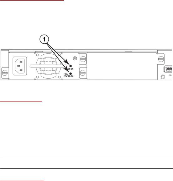
FIGURE 20 Power status LEDs |
|
|
1.Power status LEDs
TABLE 9 Power status LEDs
LED |
Condition |
Status |
|
|
|
DC OK |
Green |
DC output ok |
|
|
|
|
Red |
DC output fail |
|
|
|
AC OK |
Green |
AC input ok |
|
|
|
|
Off |
AC input fail |
|
|
|
NOTE
Both "AC OK" and "DC OK" LEDs must be green for the device to function normally.
TABLE 10 Switch status for two installed power supply units
State |
LED |
PSU1 |
PSU2 |
Switch Status |
Load Sharing |
HPOE Budget(HPOE |
|
|
|
|
|
|
models only) |
|
|
|
|
|
|
|
Four Green PSU LEDs |
AC OK |
Green |
Green |
Running |
Yes |
820W |
|
|
|
|
|
|
|
|
DC OK |
Green |
Green |
|
|
|
|
|
|
|
|
|
|
Single Red ‘DC OK’ LED |
AC OK |
Green |
Green |
Running |
No |
410W |
|
|
|
|
|
|
|
|
DC OK |
Green |
Red |
|
|
|
|
|
|
|
|
|
|
Both ‘DC OK’ LEDs Red |
AC OK |
Green |
Green |
Failure |
No |
None |
|
|
|
|
|
|
|
|
DC OK |
Red |
Red |
|
|
|
|
|
|
|
|
|
|
Brocade FCX Series Hardware Installation Guide |
27 |
53-1003077-01 |
|
Port, system, and power status LEDs for Brocade FCX 624-E, FCX 624-I, FCX 648-E, and FCX 648-I
TABLE 10 Switch status for two installed power supply units (Continued)
State |
LED |
PSU1 |
PSU2 |
Switch Status |
Load Sharing |
HPOE Budget(HPOE |
|
|
|
|
|
|
models only) |
|
|
|
|
|
|
|
One PSU with both ‘AC |
AC OK |
Green |
Off |
Running |
No |
410W |
OK’ ‘DC OK’ LEDs Off |
|
|
|
|
|
|
DC OK |
Green |
Off |
|
|
|
|
|
|
|
|
|||
|
|
|
|
|
|
|
‘DC OK’ LEDs Red and Off |
AC OK |
Green |
Off |
Failure |
No |
None |
|
|
|
|
|
|
|
|
DC OK |
Red |
Off |
|
|
|
|
|
|
|
|
|
|
All ‘AC OK’ LEDs Off |
AC OK |
Off |
Off |
Power Off or |
No |
None |
|
|
|
|
Failure |
|
|
|
DC OK |
Off |
Off |
|
|
|
|
|
|
|
|||
|
|
|
|
|
|
|
NOTE
When two 620W power supplies are installed in an HPOE system that has no load or light load on the POE function, one of two power supplies may have its "DC OK" LED light red. There is no fault in the power supply or the system and the switch is functioning normally. The LED will turn to green automatically once the load is increased over the minimum load requirement. In configurations with a single power supply installed the "DC OK" LED will light green in a no-load or light-load condition.
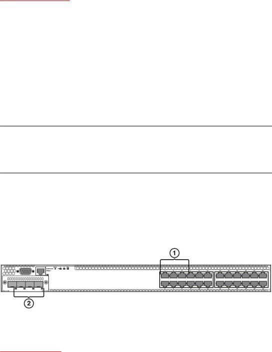
Port, system, and power status LEDs for Brocade FCX 624-E, FCX 624-I, FCX 648-E, and FCX 648-I
FCX switches include a display panel for key system and port indicators that simplifies installation and network troubleshooting. The LEDs are located on the front panel for easy viewing.
FIGURE 21 Port status LEDs
1.Port status LEDs
2.SFP or SFP+ port status LEDs
TABLE 11 Port status LEDs
LED |
Condition |
Status |
|
|
|
Ethernet(1~24/48) |
On/Flashing Green |
The port has established a valid link at 10/100/1000 Mbps. |
Link or Activity or Speed |
|
Flashing indicates the port is transmitting and receiving user |
|
packets. |
|
|
|
|
|
|
|
|
Off |
A link is not established with a remote port. |
|
|
|
28 |
Brocade FCX Series Hardware Installation Guide |
|
53-1003077-01 |
Loading...