


 Loading...
53-1002180-07
27 June 2014
Brocade DCX 8510-8
Backbone
Hardware Reference Manual
© 2014, Brocade Communications Systems, Inc. All Rights Reserved.
Brocade, the B-wing symbol, Brocade Assurance, ADX, AnyIO, DCX, Fabric OS, FastIron, HyperEdge, ICX, MLX, MyBrocade, NetIron, OpenScript, VCS, VDX, and Vyatta are registered trademarks, and The Effortless Network and the On-Demand Data Center are trademarks of Brocade Communications Systems, Inc., in the United States and in other countries. Other brands and product names mentioned may be trademarks of others.
Notice: This document is for informational purposes only and does not set forth any warranty, expressed or implied, concerning any equipment, equipment feature, or service offered or to be offered by Brocade. Brocade reserves the right to make changes to this document at any time, without notice, and assumes no responsibility for its use. This informational document describes features that may not be currently available. Contact a Brocade sales office for information on feature and product availability. Export of technical data contained in this document may require an export license from the United States government.
The authors and Brocade Communications Systems, Inc. assume no liability or responsibility to any person or entity with respect to the accuracy of this document or any loss, cost, liability, or damages arising from the information contained herein or the computer programs that accompany it.
The product described by this document may contain open source software covered by the GNU General Public License or other open source license agreements. To find out which open source software is included in Brocade products, view the licensing terms applicable to the open source software, and obtain a copy of the programming source code, please visit http://www.brocade.com/support/oscd.

Contents
Preface..................................................................................................................................... |
7 |
Document conventions...................................................................................... |
7 |
Text formatting conventions.................................................................. |
7 |
Command syntax conventions.............................................................. |
7 |
Notes, cautions, and warnings.............................................................. |
8 |
Brocade resources............................................................................................ |
9 |
Contacting Brocade Technical Support............................................................. |
9 |
Document feedback........................................................................................ |
10 |
About This Document.............................................................................................................. |
11 |
Supported hardware and software.................................................................. |
11 |
What’s new in this document.......................................................................... |
11 |
Brocade DCX 8510-8 Overview................................................................................................ |
13 |
Brocade DCX 8510-8 features........................................................................ |
13 |
Brocade DCX 8510-8 hardware components................................................. |
14 |
Port side of the Brocade DCX 8510-8................................................. |
15 |
Nonport side of the Brocade DCX 8510-8........................................... |
16 |
Brocade DCX 8510-8 blades.......................................................................... |
17 |
High availability............................................................................................... |
19 |
Reliability......................................................................................................... |
19 |
Serviceability................................................................................................... |
20 |
Software features............................................................................................ |
20 |
Security........................................................................................................... |
20 |
Network manageability.................................................................................... |
21 |
Installation of the Brocade DCX 8510-8.................................................................................. |
23 |
Time and items required................................................................................. |
23 |
Preparing for the Brocade DCX 8510-8 installation........................................ |
24 |
Unpacking and installing the Brocade DCX 8510-8........................................ |
25 |
Items included with the Brocade DCX 8510-8................................................ |
26 |
Providing power to the Brocade DCX 8510-8 Backbone................................ |
27 |
Port numbering................................................................................................ |
27 |
Chassis slots................................................................................................... |
29 |
Cable management......................................................................................... |
29 |
High-density cabling............................................................................ |
30 |
Installing ICL cables............................................................................ |
31 |
Logging In and Configuring the Brocade DCX 8510-8.............................................................. |
33 |
Configuring the Brocade DCX 8510-8............................................................. |
33 |
Establishing a serial connection to the Brocade DCX 8510-8......................... |
34 |
Logging in to the serial console port............................................................... |
35 |
Configuring the IP addresses.......................................................................... |
36 |
Logging off the serial console port and disconnecting the serial cable........... |
37 |
Establishing an Ethernet connection to the Brocade DCX 8510-8.................. |
37 |
Customizing a switch name............................................................................ |
38 |
Brocade DCX 8510-8 Backbone Hardware Reference Manual |
3 |
53-1002180-07 |
|
Customizing a chassis name........................................................................ |
38 |
Setting the domain ID.................................................................................... |
38 |
Setting the date and time.............................................................................. |
39 |
Setting the date................................................................................. |
39 |
Setting the time zone........................................................................ |
39 |
Synchronizing local time................................................................... |
40 |
Verifying the PID mode................................................................................. |
41 |
Determining installed software licenses........................................................ |
41 |
Installing transceivers and attaching cables................................................. |
41 |
Installing SFP+ and mSFP transceivers and cables......................... |
42 |
Qualified transceivers for the FC16-64 port blade and the core |
|
blades.......................................................................................... |
42 |
Installing QSFP transceivers and cables.......................................... |
43 |
Managing cables........................................................................................... |
44 |
Verifying correct operation and backing up the configuration....................... |
45 |
Powering off the Brocade DCX 8510-8......................................................... |
46 |
Monitoring System Components............................................................................................ |
47 |
Monitoring overview...................................................................................... |
47 |
Determining the status of a port or application blade.................................... |
52 |
Blade illustrations.............................................................................. |
52 |
Determining the status of a control processor blade (CP8).......................... |
63 |
Determining the status of a core switch blade (CR16-8).............................. |
65 |
Determining the status of a power supply..................................................... |
67 |
Determining the status of a blower assembly............................................... |
68 |
Determining the status of a WWN card......................................................... |
70 |
Removal and Replacement Procedures................................................................................. |
73 |
Introduction................................................................................................... |
73 |
ESD precautions........................................................................................... |
73 |
Chassis door removal and replacement....................................................... |
74 |
Time and items required................................................................... |
74 |
Removing a chassis door.................................................................. |
74 |
Replacing a chassis door.................................................................. |
75 |
Cable management comb removal and replacement................................... |
75 |
Time and items required................................................................... |
75 |
Removing a cable management comb.............................................. |
75 |
Replacing a cable management comb.............................................. |
76 |
Port, application, and encryption blade removal and replacement............... |
76 |
Time and items required................................................................... |
77 |
Removing a blade............................................................................. |
78 |
Replacing a blade............................................................................. |
79 |
Blade filler panel removal and replacement.................................................. |
80 |
Removing a filler panel...................................................................... |
80 |
Replacing a filler panel...................................................................... |
81 |
Control processor blade (CP8) removal and replacement............................ |
82 |
Time and items required................................................................... |
82 |
Faulty CP blade indicators................................................................ |
82 |
Recording critical Brocade DCX 8510-8 information........................ |
83 |
Removing a control processor blade (CP8)...................................... |
84 |
Replacing a control processor blade (CP8)...................................... |
85 |
Verifying operation of the new CP blade........................................... |
86 |
Completing the replacement............................................................. |
89 |
Core switch blade (CR16-8) removal and replacement................................ |
90 |
Time and items required................................................................... |
90 |
Faulty core switch blade indicators................................................... |
90 |
4 |
Brocade DCX 8510-8 Backbone Hardware Reference Manual |
|
53-1002180-07 |
Removing a core switch blade (CR16-8)............................................ |
90 |
Replacing a core switch blade (CR16-8)............................................. |
92 |
Power supply removal and replacement......................................................... |
93 |
Time and items required..................................................................... |
93 |
Identifying power supplies................................................................... |
93 |
Removing a power supply................................................................... |
94 |
Replacing a power supply................................................................... |
95 |
Blower assembly removal and replacement................................................... |
96 |
Time and items required..................................................................... |
96 |
Removing a blower assembly ............................................................ |
96 |
Replacing a blower assembly............................................................. |
97 |
WWN card removal and replacement............................................................. |
97 |
Time and items required..................................................................... |
98 |
Verifying the need for replacement..................................................... |
98 |
Preparing for the WWN card replacement.......................................... |
98 |
Removing the WWN card and WWN bezel (logo plate)...................... |
99 |
Replacing the WWN card and WWN bezel (logo plate).................... |
101 |
Transceiver removal and replacement.......................................................... |
101 |
Time Required................................................................................... |
102 |
Items Required.................................................................................. |
102 |
Removing an SFP+ transceiver........................................................ |
102 |
Replacing an SFP+ transceiver......................................................... |
103 |
Removing and replacing an mSFP optical transceiver..................... |
104 |
Removing and replacing a QSFP optical transceiver........................ |
105 |
Qualified transceivers for the FC16-64 port blade and the core |
|
blades.......................................................................................... |
106 |
Inter-chassis link (ICL) cable removal and replacement............................... |
106 |
Time and items required................................................................... |
108 |
Removing an ICL cable..................................................................... |
108 |
Replacing an ICL cable..................................................................... |
108 |
Possible ICL configurations............................................................... |
108 |
Brocade DCX 8510-8 chassis removal and replacement............................. |
111 |
Time and items required................................................................... |
112 |
Faulty Brocade DCX 8510-8 chassis indicators................................ |
112 |
Recording critical Brocade DCX 8510-8 and SAN information......... |
113 |
Disconnecting from network and fabric............................................. |
115 |
Removing components from the chassis.......................................... |
116 |
Installing the replacement chassis.................................................... |
116 |
Installing components into the new chassis...................................... |
117 |
Downloading the configuration.......................................................... |
118 |
Verifying correct operation of system................................................ |
118 |
Reconnecting the system to the network and fabric......................... |
120 |
Verifying correct configuration of the fabric....................................... |
120 |
Cable routing table............................................................................ |
121 |
Specifications....................................................................................................................... |
125 |
General specifications................................................................................... |
125 |
System architecture...................................................................................... |
126 |
System size and weight................................................................................ |
128 |
System blade and FRU weights.................................................................... |
128 |
Facility requirements..................................................................................... |
129 |
Environmental requirements......................................................................... |
130 |
Fibre Channel port specifications.................................................................. |
130 |
Power specifications..................................................................................... |
131 |
Power cords.................................................................................................. |
133 |
Power-cord notice............................................................................. |
136 |
Data transmission ranges............................................................................. |
137 |
Brocade DCX 8510-8 Backbone Hardware Reference Manual |
5 |
53-1002180-07 |
|
Qualified cables for the FC8-64 port blade................................................. |
138 |
Cable types supported on the FC16-64 port blade..................................... |
139 |
Application and Encryption Blades...................................................................................... |
141 |
Introduction................................................................................................. |
141 |
FS8-18 blade............................................................................................... |
141 |
FX8-24 blade............................................................................................... |
141 |
FCOE10-24 blade....................................................................................... |
143 |
Limitations of FCOE10-24 blade..................................................... |
144 |
Diagnostics and Troubleshooting........................................................................................ |
145 |
Introduction................................................................................................. |
145 |
Obtaining chassis and component status................................................... |
145 |
Interpreting POST and boot results............................................................ |
146 |
POST.............................................................................................. |
146 |
Boot................................................................................................. |
147 |
Diagnostics.................................................................................................. |
147 |
Troubleshooting.......................................................................................... |
148 |
Port Numbering Template................................................................................................... |
151 |
Regulatory Statements....................................................................................................... |
163 |
Regulatory compliance................................................................................ |
163 |
FCC warning (US only)................................................................... |
163 |
KCC statement (Republic of Korea)................................................ |
163 |
VCCI statement (Japan).................................................................. |
163 |
Power-cord notice (Japan, Denan)................................................. |
164 |
BSMI statement (Taiwan)................................................................ |
164 |
CE statement.................................................................................. |
164 |
Canadian requirements................................................................... |
165 |
German statement.......................................................................... |
165 |
Regulatory compliance standards................................................... |
165 |
Environmental regulation compliance......................................................... |
166 |
China RoHS.................................................................................... |
166 |
Caution and Danger Notices................................................................................................ |
167 |
Cautions...................................................................................................... |
167 |
Danger Notices........................................................................................... |
168 |
Index.................................................................................................................................. |
173 |
6 |
Brocade DCX 8510-8 Backbone Hardware Reference Manual |
|
53-1002180-07 |

Preface
● Document conventions...................................................................................................... |
7 |
● Brocade resources............................................................................................................ |
9 |
● Contacting Brocade Technical Support............................................................................. |
9 |
● Document feedback........................................................................................................ |
10 |
Document conventions
The document conventions describe text formatting conventions, command syntax conventions, and important notice formats used in Brocade technical documentation.
Text formatting conventions
Text formatting conventions such as boldface, italic, or Courier font may be used in the flow of the text to highlight specific words or phrases.
Format
bold text
italic text
Courier font
Description
Identifies command names
Identifies keywords and operands
Identifies the names of user-manipulated GUI elements Identifies text to enter at the GUI
Identifies emphasis
Identifies variables and modifiers
Identifies paths and Internet addresses
Identifies document titles
Identifies CLI output
Identifies command syntax examples
Command syntax conventions
Bold and italic text identify command syntax components. Delimiters and operators define groupings of parameters and their logical relationships.
Convention |
Description |
bold text |
Identifies command names, keywords, and command options. |
italic text |
Identifies a variable. |
Brocade DCX 8510-8 Backbone Hardware Reference Manual |
7 |
53-1002180-07 |
|

Notes, cautions, and warnings
Convention |
Description |
value |
In Fibre Channel products, a fixed value provided as input to a command |
|
option is printed in plain text, for example, --show WWN. |
[ ] |
Syntax components displayed within square brackets are optional. |
|
Default responses to system prompts are enclosed in square brackets. |
{ x | y | z }
x | y
< >
...
\
A choice of required parameters is enclosed in curly brackets separated by vertical bars. You must select one of the options.
In Fibre Channel products, square brackets may be used instead for this purpose.
A vertical bar separates mutually exclusive elements.
Nonprinting characters, for example, passwords, are enclosed in angle brackets.
Repeat the previous element, for example, member[member...].
Indicates a “soft” line break in command examples. If a backslash separates two lines of a command input, enter the entire command at the prompt without the backslash.
Notes, cautions, and warnings
Notes, cautions, and warning statements may be used in this document. They are listed in the order of increasing severity of potential hazards.
NOTE
A Note provides a tip, guidance, or advice, emphasizes important information, or provides a reference to related information.
ATTENTION
An Attention statement indicates a stronger note, for example, to alert you when traffic might be interrupted or the device might reboot.
CAUTION
A Caution statement alerts you to situations that can be potentially hazardous to you or cause damage to hardware, firmware, software, or data.
DANGER
A Danger statement indicates conditions or situations that can be potentially lethal or extremely hazardous to you. Safety labels are also attached directly to products to warn of these conditions or situations.
8 |
Brocade DCX 8510-8 Backbone Hardware Reference Manual |
|
53-1002180-07 |

Brocade resources
Brocade resources
Visit the Brocade website to locate related documentation for your product and additional Brocade resources.
You can download additional publications supporting your product at www.brocade.com. Select the Brocade Products tab to locate your product, then click the Brocade product name or image to open the individual product page. The user manuals are available in the resources module at the bottom of the page under the Documentation category.
To get up-to-the-minute information on Brocade products and resources, go to MyBrocade. You can register at no cost to obtain a user ID and password.
Release notes are available on MyBrocade under Product Downloads.
White papers, online demonstrations, and data sheets are available through the Brocade website.
Contacting Brocade Technical Support
As a Brocade customer, you can contact Brocade Technical Support 24x7 online, by telephone, or by e- mail. Brocade OEM customers contact their OEM/Solutions provider.
Brocade customers
For product support information and the latest information on contacting the Technical Assistance Center, go to http://www.brocade.com/services-support/index.html.
If you have purchased Brocade product support directly from Brocade, use one of the following methods to contact the Brocade Technical Assistance Center 24x7.
Online |
Telephone |
|
|
|
|
Preferred method of contact for nonurgent issues:
Required for Sev 1-Critical and Sev support@brocade.com
2-High issues:
Please include:
• My Cases through MyBrocade |
• Continental US: 1-800-752-8061 |
• Software downloads and licensing |
• Europe, Middle East, Africa, and |
tools |
Asia Pacific: +800-AT FIBREE |
• Knowledge Base |
(+800 28 34 27 33) |
|
• For areas unable to access toll |
|
free number: +1-408-333-6061 |
|
• Toll-free numbers are available in |
|
many countries. |
•Problem summary
•Serial number
•Installation details
•Environment description
Brocade OEM customers
If you have purchased Brocade product support from a Brocade OEM/Solution Provider, contact your OEM/Solution Provider for all of your product support needs.
•OEM/Solution Providers are trained and certified by Brocade to support Brocade® products.
•Brocade provides backline support for issues that cannot be resolved by the OEM/Solution Provider.
Brocade DCX 8510-8 Backbone Hardware Reference Manual |
9 |
53-1002180-07 |
|
Document feedback
•Brocade Supplemental Support augments your existing OEM support contract, providing direct access to Brocade expertise. For more information, contact Brocade or your OEM.
•For questions regarding service levels and response times, contact your OEM/Solution Provider.
Document feedback
To send feedback and report errors in the documentation you can use the feedback form posted with the document or you can e-mail the documentation team.
Quality is our first concern at Brocade and we have made every effort to ensure the accuracy and completeness of this document. However, if you find an error or an omission, or you think that a topic needs further development, we want to hear from you. You can provide feedback in two ways:
•Through the online feedback form in the HTML documents posted on www.brocade.com.
•By sending your feedback to documentation@brocade.com.
Provide the publication title, part number, and as much detail as possible, including the topic heading and page number if applicable, as well as your suggestions for improvement.
10 |
Brocade DCX 8510-8 Backbone Hardware Reference Manual |
|
53-1002180-07 |
About This Document
● Supported hardware and software.................................................................................. |
11 |
● What’s new in this document.......................................................................................... |
11 |
Supported hardware and software
This document includes information specific to the Brocade DCX 8510-8 running Brocade Fabric OS version 7.0.0 and later.
What’s new in this document
The following information has been added or modified:
•Support for the new FC16-64 port blade.
•Support for the new FCOE10-24 port blade.
•WWN card removal and replacement procedure.
Brocade DCX 8510-8 Backbone Hardware Reference Manual |
11 |
53-1002180-07 |
|
What’s new in this document
12 |
Brocade DCX 8510-8 Backbone Hardware Reference Manual |
|
53-1002180-07 |

Brocade DCX 8510-8 Overview |
|
● Brocade DCX 8510-8 features........................................................................................ |
13 |
● Brocade DCX 8510-8 hardware components................................................................. |
14 |
● Brocade DCX 8510-8 blades.......................................................................................... |
17 |
● High availability............................................................................................................... |
19 |
● Reliability......................................................................................................................... |
19 |
● Serviceability................................................................................................................... |
20 |
● Software features............................................................................................................ |
20 |
● Security........................................................................................................................... |
20 |
● Network manageability.................................................................................................... |
21 |
Brocade DCX 8510-8 features |
|
Key features of the Brocade DCX 8510-8 include: |
|
•Up to 512 16-Gbps external ports in a single chassis , enabling high density SAN configurations with reduced footprint.
•Support for 2, 4, 8, and 16 Gbps autosensing Fibre Channel ports. Trunking technology groups up to eight ports to create high performance 128-Gbps ISL trunks between switches.
•The Brocade DCX 8510-8 also supports 10-Gbps FC-type SFPs in 32/48-port 16-Gbps port blades, and 10-GbE SFPs in the FX8-24 and FCOE10-24 application blades . The two types of SFPs are not interchangeable.
•The 10-Gbps port speed can be manually configured on any port of the 32and 48-port 16-Gbps port blades.
•Support for many of the application, port blade, and control processor (CP) blades supported in the Brocade DCX family of backbones (with the exception of the Core Switch Blade), thereby providing flexible system configurations and fewer types of new blades.
•Beginning with Fabric OS v7.0.1, up to nine chassis can be connected with the use of 4x16 Gbps quad SFP (QSFP) inter-chassis links (ICLs). Fabric OS v7.0.0 permits up to six chassis to be linked.
•Support for high-performance port blades running at 2, 4, 8, 10, or 16-Gbps, enabling flexible system configuration.
•Redundant and hot-swappable control processor and core switch blades, power supplies, blower assemblies, and WWN cards that enable a high availability platform and enable nondisruptive software upgrades for mission-critical SAN applications.
•Universal ports that self-configure as E_Ports, F_Ports, EX_Ports and M_Ports (mirror ports). 10Gbps ports are E_Ports only.
•Diagnostic port (D_Port) functionality.
•In-flight data cryptographic (encryption/decryption) and data compression capabilities through the 16Gbps port blades when configured as ISLs.
•Fibre Channel over IP (FCIP) functionality through the FX8-24 blade.
•Fibre Channel over Ethernet (FCoE) capability through the FCOE10-24 blade.
Brocade DCX 8510-8 Backbone Hardware Reference Manual |
13 |
53-1002180-07 |
|
Brocade DCX 8510-8 hardware components
Brocade DCX 8510-8 hardware components
The Brocade DCX 8510-8 features a modular and scalable mechanical construction that allows a wide range of flexibility in installation, fabric design, and maintenance. The chassis can be mounted with the cables facing the front of the equipment rack or to the rear, and consists of the following:
•Up to eight hot-swappable port blade assemblies that can be configured in a single chassis, delivering up to 512 16-Gbps Fibre Channel ports.
•Two slots for control processor blades (CP8):
A single active CP8 blade can control all 512 ports in the chassis.
The standby CP8 blade assumes control of the Brocade DCX 8510-8 if the active CP fails.
•Two slots for core switch blades (CR16-8):
CR16-8 blade interconnects all port blades.
Inter-chassis link (ICL) connectors to connect to as many as nine neighboring chassis using Fabric OS v7.0.1 or later. Only six chassis can be connected using Fabric OS v7.0.0.
Both CR16-8 blades are active.
•Modular, hot-swappable port blades:
32-port, 8-Gbps blades (FC8-32E)
48-port, 8-Gbps blades (FC8-48E)
64-port, 8-Gbps blades (FC8-64)
32-port, 16-Gbps blades (FC16-32)
48-port, 16-Gbps blades (FC16-48)
64-port, 16-Gbps blades (FC16-64)
•Modular, hot-swappable application blades:
FX8-24: 24-port (12 FC, 10 1-GbE, and 2 10-GbE) FCIP extension blade enabling long distance communication over existing IP infrastructure.
FCOE10-24: 24-port (24 10-GbE) CEE-based FCoE blade enabling enhanced connectivity using existing Ethernet infrastructure. The FCoE blade can be used in the same chassis with only the FC8-32E and FC16-32 port blades. The FCoE blade cannot be used with any other FC port or application blades in the same chassis.
•Modular, hot-swappable encryption blades:
FS8-18: 16-port, up to 4 blades per chassis, supporting in-flight data cryptographic (encryption/decryption) and data-compression capabilities.
•Modular, hot-swappable field-replaceable units (FRUs):
Three blower assemblies.
Up to four power supplies (100-240 VAC autosensing).
At 110 VAC (nominal): Four power supplies are required for high availability.
220 VAC (nominal) is recommended for efficiency. Two or four power supplies are provided depending on the quantity ordered. Refer to "Power specifications" in the "Specifications" appendix for specific requirements for high availability.
Redundant AC primary power connections ensure high availability. Each power supply has its own connector, so the number of primary power connections is four for optimum efficiency and redundancy.
Two WWN cards.
Blades use small form-factor pluggable (SFP+, mSFP, and QSFP) optical transceivers.
The 8-Gbps SFP+s and mSFPs auto-negotiate at 2, 4, and 8 Gbps.
The 10-Gbps speeds must be manually set and require special 10-Gbps FC SFP + transceivers.
The 16-Gbps SFP+ transceivers support speeds of 2, 4, 8, 10, and 16 Gbps.
14 |
Brocade DCX 8510-8 Backbone Hardware Reference Manual |
|
53-1002180-07 |

Port side of the Brocade DCX 8510-8
The 16-Gbps QSFPs supported on FC16-64 prot blade auto-negotiate at 4, 8, and 16 Gbps.
The 16-Gbps QSFPs based inter-chassis link (ICL) on the core blades run at 64 Gbps (four fixed 16-Gbps clustered in a single quad connector and cable).
•Blades that are serviced from the port side of the Brocade DCX 8510-8. Blowers, power supplies, and power cables that are serviced from the nonport side.
•World Wide Name (WWN) cards on the nonport side, to maintain chassis-specific information such as WWNs, IP addresses, and summary status information of each port blade and power supply through LEDs.
•Redesigned cable management comb and chassis door.
Port side of the Brocade DCX 8510-8
NOTE
Airflow in the Brocade DCX 8510-8 is from the nonport (noncable) side to the port (cable) side and out the exhaust vent.
Brocade DCX 8510-8 Backbone Hardware Reference Manual |
15 |
53-1002180-07 |
|

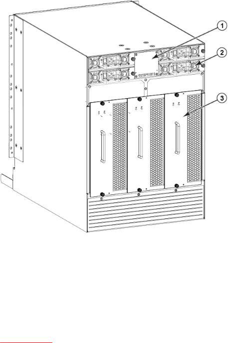
Nonport side of the Brocade DCX 8510-8
FIGURE 1 Port side of the Brocade DCX 8510-8 (sample configuration)
1.Exhaust vent
2.Core switch blade (CR16-8)
3.Control processor blade (CP8)
4.FC16-32 port blade
5.Cable management comb
Nonport side of the Brocade DCX 8510-8
The following figure shows a sample configuration of the nonport side view of the Brocade DCX 8510-8.
16 |
Brocade DCX 8510-8 Backbone Hardware Reference Manual |
|
53-1002180-07 |
Brocade DCX 8510-8 blades
FIGURE 2 Nonport side of the Brocade DCX 8510-8 (sample configuration)
1.WWN bezel (logo plate - WWN card behind)
2.Power supply
3.Blower assembly
Brocade DCX 8510-8 blades
The following table summarizes the port, application, control processor, and core switch blades that are available for the Brocade DCX 8510-8.
TABLE 1 Blades available for the Brocade DCX 8510-8
Description |
Name |
Function |
|
|
|
Brocade DCX |
CP8 |
The CP8 blade contains the control plane for the chassis. There are two CP8 |
8510-8 control |
|
blades for redundancy. This control processor blade is compatible with the |
processor blade |
|
Brocade DCX 8510-8, Brocade DCX 8510-4, Brocade DCX, and Brocade |
|
|
DCX-4S. |
|
|
|
Brocade DCX 8510-8 Backbone Hardware Reference Manual |
17 |
53-1002180-07 |
|

Brocade DCX 8510-8 Overview
TABLE 1 Blades available for the Brocade DCX 8510-8 (Continued)
Description |
Name |
Function |
|
|
|
Brocade DCX |
CR16-8 |
The CR16-8 blade contains the ASICs for switching between port blades. |
8510-8 core switch |
|
Every port blade connects to each core switch blade. There can be up to 512 |
blade |
|
16-Gbps or 8-Gbps total ports for port blades. Each core switch blade connects |
|
|
to 128 backplane ports. Core switch blades have additional front port |
|
|
connectivity to connect multiple chassis and backplane connections for the |
|
|
storage server blade. This core switch blade is compatible only with the |
|
|
Brocade DCX 8510-8. Requires specific type of QSFP transceivers. |
|
|
|
32-port 8-Gbps port |
FC8-32E |
A 32-port Brocade port blade supporting 2, 4, and 8 Gbps Fibre Channel port |
blade |
|
speeds. This port blade is compatible with the Brocade DCX 8510-8 and |
|
|
Brocade DCX 8510-4. This blade requires Fabric OS v7.0.1 or later to run in |
|
|
this chassis. |
|
|
|
48-port 8-Gbps port |
FC8-48E |
A 48-port Brocade port blade supporting 2, 4, and 8 Gbps Fibre Channel port |
blade |
|
speeds. This port blade is compatible with the Brocade DCX 8510-8 and |
|
|
Brocade DCX 8510-4. This blade requires Fabric OS v7.0.1 or later to run in |
|
|
this chassis. |
|
|
|
64-port 8-Gbps port |
FC8-64 |
A 64-port Brocade port blade supporting 2, 4, and 8 Gbps port speeds with |
blade |
|
mSFPs. This port blade is compatible with the Brocade DCX 8510-8, Brocade |
|
|
DCX 8510-4, Brocade DCX, and Brocade DCX-4S. |
|
|
|
32-port 16-Gbps |
FC16-32 |
A 32-port Brocade port blade supporting 2, 4, 8, 10, and 16 Gbps Fibre |
port blade |
|
Channel port speeds. The blade also supports port-based in-flight encryption/ |
|
|
decryption and compression/decompression. This port blade is compatible with |
|
|
the Brocade DCX 8510-8 and Brocade DCX 8510-4 and requires Fabric OS |
|
|
v7.0.0 or later to run in this chassis. |
|
|
|
48-port 16-Gbps |
FC16-48 |
A 48-port Brocade port blade supporting 2, 4, 8, 10, and 16 Gbps Fibre |
port blade |
|
Channel port speeds. The blade also supports port-based in-flight encryption/ |
|
|
decryption and compression/decompression. This port blade is compatible with |
|
|
the Brocade DCX 8510-8 and Brocade DCX 8510-4 and requires Fabric OS |
|
|
v7.0.0 or later to run in this chassis. |
|
|
|
64-port 16-Gbps |
FC16-64 |
A 64-port Brocade port blade supporting 4, 8, and 16-Gbps Fibre Channel port |
port blade |
|
speeds. The blade also supports port-based in-flight encryption/decryption and |
|
|
compression/decompression. This port blade is compatible with the Brocade |
|
|
DCX 8510-8 and Brocade DCX 8510-4 and requires Fabric OS v7.3.0 or later |
|
|
to run in this chassis. Requires specific type of QSFP transceivers and those |
|
|
are not the same as used in the core blades. |
|
|
|
Fibre Channel over |
FCOE10-24 The FCOE10-24 blade enables FCoE functionality over existing Ethernet |
|
Ethernet blade |
|
infrastructure utilizing CEE protocols. It has 24 10-GbE ports available. This |
|
|
FCoE application blade is compatible with the Brocade DCX, Brocade |
|
|
DCX-4S, and Brocade DCX 8510-8 chassis.This FCoE blade can be used in |
|
|
the same chassis with only the FC8-32E and FC16-32 port blades. This FCoE |
|
|
blade cannot be used with any other FC port blades or application blades in |
|
|
the same chassis. Refer to the Fabric OS Release Notes for limitations in using |
|
|
this blade. |
|
|
|
Storage encryption |
FS8-18 |
The FS8-18 blade enables data cryptographic (encryption/decryption) and |
blade |
|
data-compression capabilities for data-at-rest. It has 16 Fibre Channel optical |
|
|
SFP ports. This application blade is compatible with the Brocade DCX 8510-8, |
|
|
Brocade DCX 8510-4, Brocade DCX, and Brocade DCX-4S and requires |
|
|
Fabric OS v7.0.0 or later to run in the 8510-4 and 8510-8 chassis. |
|
|
|
18 |
Brocade DCX 8510-8 Backbone Hardware Reference Manual |
|
53-1002180-07 |

High availability
TABLE 1 Blades available for the Brocade DCX 8510-8 (Continued)
Description |
Name |
Function |
|
|
|
FCIP extension |
FX8-24 |
The FX8-24 blade enables FCIP functionality over existing IP infrastructure. It |
blade |
|
has 12 FC ports, 10 1-GbE ports, and two 10-GbE ports available. This |
|
|
application blade is compatible with the Brocade DCX 8510-8, Brocade DCX |
|
|
8510-4, Brocade DCX, and Brocade DCX-4S and requires Fabric OS v7.0.0 or |
|
|
later to run in the DCX 8510-4 and DCX 8510-8 chassis. |
|
|
|
High availability
The following features contribute to the Brocade DCX 8510-8 high availability design:
•Redundant, hot-swappable FRUs, including blades, power supplies, blowers, and WWN cards
•Enhanced data integrity on all data paths
•Fabric Shortest Path First (FSPF) rerouting around failed links
•Integration with Simple Network Management Protocol (SNMP) managers
•Automatic control processor failover
•Nondisruptive "hot" software code loads and activation
•Easy configuration, save, and restore
The high availability software architecture of the Brocade DCX 8510-8 provides a common framework for all applications that reside on the system, allowing global and local states to be maintained through any component failure. High availability elements consist of the High Availability Manager, the heartbeat, the fault/health framework, the replicated database, initialization, and software upgrade.
The High Availability Manager controls access to the standby control processor, facilitates software upgrades, prevents extraneous CP failover activity, closes and flushes streams, provides flow control and message buffering, and supports a centralized active and standby state.
Reliability
The Brocade DCX 8510-8 uses the following error detection and correction mechanisms to ensure reliability of data:
•Error Detection and Correction over main control processor memory.
•Error Detection and Correction mechanism, which checks for encoder errors and fault isolation (EDFI), such as cyclic redundancy checking (CRC), parity checking, checksum, and illegal address checking.
•Power-on self-test (POST).
•Dual control processors that enable hot, nondisruptive fast firmware upgrades.
•One serial port and two Ethernet ports (on each control processor) for management and for service. Offline control processor diagnostics and remote diagnostics simplify troubleshooting. The standby control processor monitors diagnostics to ensure the system is operational should a failover be necessary.
•Bus monitoring and control of blades and other field-replaceable units (FRUs).
Brocade DCX 8510-8 Backbone Hardware Reference Manual |
19 |
53-1002180-07 |
|
Serviceability
Serviceability
The Brocade DCX 8510-8 provides the following features to enhance and ensure serviceability:
•Modular design with hot-swappable components.
•Flash memory that stores two firmware images per control processor.
•USB port on control processor blades for most tasks that formerly required an FTP/SCP server, including software and firmware upgrades.
•Nonvolatile random-access memory (NVRAM), containing the OEM serial number, Brocade serial number, revision information, and part number information.
•Background health-check daemon.
•Memory scrubber, self test, and bus ping to determine if a bus is not functioning.
•RASlog messages.
•SMI-S compliant.
•Hardware and software watchdog timers.
•Status LEDs.
•Predictive diagnostics analysis through Fabric Watch.
•SNMP (including version 3) integration with higher-layer managers.
Software features
The Fabric OS allows any Fibre Channel-compliant device to attach to the switches as long as it conforms to the device login, name service, and related Fibre Channel standards. Each operating environment requires that a Fibre Channel host bus adapter (HBA) be available with a standardscompliant driver for correct interface to the fabric.
Fabric OS consists of a set of embedded applications running on top of an embedded Linux operating system kernel. Some of these applications include:
•Name server
•Alias server
•Zone server
•Simple Network Management Protocol (SNMP) agent
•SMI-S compliant API
•Syslog auditing
•Reliable Commit Service (RCS)
•NTP
•Tasks to manage address assignment, routing, link initialization, fabric initialization, link shutdown, Brocade DCX 8510-8 shutdown, and the user interface
Security
The following list highlights some of the key security features available for the Brocade DCX 8510-8 and for other Brocade enterprise-class products running Fabric OS 7.0.1 or later. For details, contact your Brocade DCX 8510-8 supplier and refer to the Brocade White Paper, "The Growing Need for Security in Storage Area Networks."
20 |
Brocade DCX 8510-8 Backbone Hardware Reference Manual |
|
53-1002180-07 |
Network manageability
•DH-CHAP
•SSHv2 (using AES, 3DES, RSA)
•HTTPS (using AES)
•SNMPv3
•FC-SP
•Secure RPC
•Secure file copy (SCP)
•Telnet disable
•Telnet timeout
•IP filters (block listeners)
•Secure passwords (centralized control through RADIUS/CHAP)
•Multiple user accounts (MUAs) (Up to 255)
•Role-based access controls (RBACs)
•Administrative domains/Virtual fabrics
•Boot PROM password reset
•Password hardening policies
•Up front login in Web Tools
•Login banner
•Monitoring of attempted security breaches (through audit logging)
•Monitoring of attempted security breaches (through Fabric Watch Security Class)
•Fibre Channel security policies: DCC and SCC
•Trusted Switch (FCS) for central security management
•Management access controls (SNMPv3, Telnet, FTP, serial port, front panel)
•Hardware-enforced zoning by WWN, domain/port ID, or both
•Default zoning
•RSCN suppression and aggregation
•Configurable RSCN suppression by port
•NTPv3 (to synchronize timestamps)
•Event auditing
•Change tracking
•Firmware change alerts in Fabric Manager
•Persistent port disable
•Persistent domain ID
•E_Port disable
Network manageability
The Brocade DCX 8510-8 has a single domain and is managed as a single element with Brocade Network Advisor. The Brocade DCX 8510-8 responds to its own IP address and appears as a separate entity to the Telnet protocol and SNMP.
All management interfaces, such as Telnet, Web Tools, standards-compliant SMI-S, and Management Server, support a "port N within blade M" naming scheme.
The Brocade DCX 8510-8 supports SNMPv1 and SNMPv3. When SNMP devices send SNMP messages to a management console running SAN management software, the information is stored in a management information base (MIB). Fabric OS v7.0.0 and later supports the latest Fibre Alliance Fibre Channel Management (FCMGMT) and Storage Management Initiative (SMI) MIBs, which allow common information necessary for management software to provide information to a SAN administrator. Refer to the Fabric OS MIB Reference for additional MIB information.
Brocade DCX 8510-8 Backbone Hardware Reference Manual |
21 |
53-1002180-07 |
|
Network manageability
22 |
Brocade DCX 8510-8 Backbone Hardware Reference Manual |
|
53-1002180-07 |

Installation of the Brocade DCX 8510-8 |
|
● Time and items required................................................................................................. |
23 |
● Preparing for the Brocade DCX 8510-8 installation........................................................ |
24 |
● Unpacking and installing the Brocade DCX 8510-8........................................................ |
25 |
● Items included with the Brocade DCX 8510-8................................................................ |
26 |
● Providing power to the Brocade DCX 8510-8 Backbone................................................ |
27 |
● Port numbering................................................................................................................ |
27 |
● Chassis slots................................................................................................................... |
29 |
● Cable management......................................................................................................... |
29 |
Time and items required |
|
You can set up and install the Brocade DCX 8510-8 in the following ways: |
|
•As a standalone unit on a flat surface.
•In a 19-inch Electronic Industries Association (EIA) cabinet, using the 14U Rack Mount Kit (provided).
•In a mid-mount telecommunications (Telco) rack, using the Mid-Mount Rack Kit available from your Brocade DCX 8510-8 supplier.
This chapter describes how to set up the Brocade DCX 8510-8 as a standalone unit. For rack-mount installation instructions, refer to the appropriate manual as described in the following table.
The following table describes the main installation and setup tasks, the estimated time required for each, and the items required to complete the task based on a fully populated Brocade DCX 8510-8 (512 Fibre Channel ports using the FC16-64 port blades). Configurations with fewer ports require less time. These time estimates assume a prepared installation site and appropriate power and network connectivity.
TABLE 2 Installation tasks, time, and items required
Installation task |
Time estimate |
Items required |
|
|
|
|
|
Site preparation and unpacking |
30 minutes |
1/2-in. socket wrench (to remove pallet bolts). |
|
Brocade DCX 8510-8 |
|
#2 Phillips screwdriver(for cable management comb). |
|
|
|
||
|
|
Pallet jack. |
|
|
|
Hydraulic lift or assisted lift, able to raise to a minimum of |
|
|
|
140 cm (55 in.), with a minimum capacity of 115 kg (254 |
|
|
|
lb). The Brocade DCX 8510-8 weighs 161.2 kg (355 lb) |
|
|
|
with eight FC16-64 port blades installed (512 ports). |
|
|
|
|
|
Installing rack mount kit |
30 minutes |
Refer to the 14U Rack Mount Kit Installation Procedure or |
|
|
|
the Mid-Mount Rack Kit Installation Procedure. |
|
Mounting and securing Brocade |
30 minutes |
||
|
|||
DCX 8510-8 in rack |
|
|
|
|
|
|
Brocade DCX 8510-8 Backbone Hardware Reference Manual |
23 |
53-1002180-07 |
|

Preparing for the Brocade DCX 8510-8 installation
TABLE 2 Installation tasks, time, and items required (Continued)
Installation task |
Time estimate |
Items required |
|
|
|
Installing power cables and |
20 minutes |
Power cables (provided in the Brocade DCX 8510-8 |
powering on the Brocade DCX |
|
accessory kit). |
8510-8 |
|
|
Establishing serial connection, |
20 minutes |
logging in to Brocade DCX 8510-8, |
|
and configuring IP addresses |
|
Serial cable (provided in the accessory kit).
Workstation computer with a serial port or terminal server port and a terminal emulator application (such as
HyperTerminal).
Ethernet IP addresses for the Brocade DCX 8510-8 chassis and for both control processor blades: total three addresses.
Installing an Ethernet cable, |
20 minutes |
Ethernet cabling (optional) for Telnet access. |
opening a Telnet session, and |
|
Refer to the Fabric OS Administrator's Guide. |
configuring the Brocade DCX |
|
|
|
|
|
8510-8 domain ID, date and time, |
|
|
and additional system parameters. |
|
|
Verify and back up configuration. |
|
|
|
|
|
Installing transceivers as needed |
30 minutes |
SFP+, mSFP, and QSFP optical transceivers as needed. |
|
(longer if using |
|
|
high-density port |
|
|
blades) |
|
|
|
|
Attaching fiber-optic cables, cable |
2-3 hours |
Fiber-optic cables, cable ties, and cable management |
ties, and cable guides |
|
comb. |
|
|
|
Preparing for the Brocade DCX 8510-8 installation
NOTE
Read the Caution and Danger Notices before installation. Read Power specifications on page 131 to plan for meeting power supply standards before installing the chassis. Read Cable management on page 29 to plan for cable management.
The following steps are required to ensure correct installation and operation.
1.Provide a space that is 14 rack units (14U) high, 61.29 cm (24.09 in.) deep, and 43.74 cm (17.22 in.) wide. 1U is equal to 4.45 cm (1.75 in.).
Plan to install the Brocade DCX 8510-8 with the nonport side facing the air-intake aisle. The Brocade DCX 8510-8 can be installed facing either direction, if serviceability and cooling requirements are met.
2.Ensure that dedicated electrical branch circuits with the following characteristics are available:
NOTE
Refer to Power specifications on page 131 for specific requirements depending on your chassis configuration.
24 |
Brocade DCX 8510-8 Backbone Hardware Reference Manual |
|
53-1002180-07 |

Unpacking and installing the Brocade DCX 8510-8
•200 - 240 VAC, 50-60 Hz (two branch circuits) - recommended for high availability and maximum blade usage when configured with 192 16 Gbps ports (four circuits required for high availability if configured with 384 16 Gbps ports)
•110 - 120 VAC, 50-60 Hz (four branch circuits highly recommended)
•Two or four cables for 200 - 240 VAC service; up to four cables for 110 - 120 VAC service
•Protected by a circuit breaker in accordance with local electrical codes
•Supply circuit, line fusing, and wire size adequate to the electrical rating on the chassis nameplate
•Location close to the chassis and easily accessible
•Grounded outlets installed by a licensed electrician and compatible with the power cords
CAUTION
Use a separate branch circuit for each power cord, which provides redundancy in case one of the circuits fails.
3.Plan for cable management before installing the chassis.
Cables can be managed in a variety of ways, such as by routing cables below the chassis, to either side of the chassis, through cable channels on the sides of the cabinet, or by using patch panels.
4.Ensure that the following is available for configuration of the Brocade DCX 8510-8:
•Workstation with an installed terminal emulator, such as HyperTerminal
•Serial cable (provided)
•Three Ethernet cables (including one spare)
•Access to an FTP server for backing up the switch configuration or collecting supportsave output data (optional)
•A Brocade USB stick for collecting supportsave output data (optional)
•Transceivers (copper and optical) and compatible cables
5.Ensure that the air intake and exhaust vents have a minimum of 5.1 cm (2 in.) of airspace.
6.Ensure that the air temperature on the air intake side is less than 40°C (104°F) during operation.
Unpacking and installing the Brocade DCX 8510-8
Use the following procedure to unpack and install your Brocade DCX 8510-8.
DANGER
A fully populated Brocade DCX 8510-8 (eight FC16-64 port cards, 512 ports) weighs approximately 161.2 kg (355 lbs) and requires a hydraulic or assisted lift to install it.
1.Unpack the Brocade DCX 8510-8.
a)Cut the bands that encircle the packaging.
b)Remove the lid and the kits and foam from the top of the chassis.
c)Lift the cardboard box off the chassis and remove the plastic bag from around the chassis.Save the packing materials for use when returning the old chassis.
d)Leave the chassis on top of the plastic shipping tray if the chassis must be transported to the installation location.
Brocade DCX 8510-8 Backbone Hardware Reference Manual |
25 |
53-1002180-07 |
|

Items included with the Brocade DCX 8510-8
NOTE
The Brocade DCX 8510-8 packaging does not incorporate a wood pallet and pallet brackets. The chassis sits on top of a plastic shipping tray.
2.Use a pallet jack or other assisted lift to transport the new chassis to the installation area. Doorways must be wider than 36 in. (91 cm) to accommodate the chassis.
3.Remove the 14U Rack Mount Kit, accessory kit, packing foam, and antistatic plastic from the chassis and set aside.
4.Remove the chassis door from the Brocade DCX 8510-8.
5.Remove the cable management comb.
6.Use a lift to raise the chassis to the correct level. If installing the chassis in a cabinet, follow the instructions provided by the rack kit manufacturer.
7.If applicable, lock the wheels of the lift.
8.Gently slide the chassis onto the final installation surface, ensuring that it remains supported during the transfer.
9.Ensure that the chassis is oriented so that the nonport side has access to intake air (cool). 10.Reinstall the cable management comb.
11.Reinstall the door. The door must be installed to meet EMI compliance.
Items included with the Brocade DCX 8510-8
The Brocade DCX 8510-8 ships with the following:
•Brocade DCX 8510-8 chassis, populated with:
Control processor blades (CP8)
Core switch blades (CR16-8)
Port blades, application blades, and encryption blades (included based on customer specification)
Blade slot filler panels (for slots not filled by blades)
WWN cards
WWN bezel (logo plate)
Power supplies
Power supply filler panel (included if there are fewer than four power supplies)
Blower assemblies
Cable management comb
Chassis door
•Accessory kit containing the following items:
Brocade DCX 8510-8 Backbone QuickStart Guide
ESD grounding strap
USB device
RS-232 serial cable. The RS-232 cable has an adapter at one end that can be removed to provide an RJ-45-style connector.
•14U Rack Mount Kit with instructions (includes rear brackets and bottom support rails)
Order the Brocade-branded optical transceivers (SFP+, mSFP, and QSFP). The Brocade DCX 8510-8 supports SWL, LWL, and ELWL transceivers. The mSFPs and QSFPs are SWL transceivers only.
26 |
Brocade DCX 8510-8 Backbone Hardware Reference Manual |
|
53-1002180-07 |

Providing power to the Brocade DCX 8510-8 Backbone
NOTE
For information about the SFP+, mSFP, and QSFP transceivers that are qualified for the Brocade DCX 8510-8, go to http://www.brocade.com/downloads/documents/matrices/sfp-matrix-mx.pdf .
Providing power to the Brocade DCX 8510-8 Backbone
For this procedure, refer to Power specifications on page 131 for power supply requirements for your chassis.
Complete the following steps to provide power to the chassis.
DANGER
Make sure that the power source circuits are properly grounded, then use the power cord supplied with the device to connect it to the power source.
1.Connect the AC power cords to the power supply assemblies. Two or four power cords are required depending on electrical service and if the high availability option is selected.
2.Connect the power cords to a power source with voltage of 200 to 240 VAC, 47 to 63 Hz (normally two power cords or as many as four) or optionally to a power source with voltage of 110 to 120 VAC, 47 to 63 Hz (up to four power cords).
NOTE
Use of the high-voltage line (200 to 240 VAC) is highly recommended because of better powerconversion efficiency. A DCX 8510-8 chassis fully loaded with 16 Gbps port blades (512 ports total) should be supplied with four power supplies connected to 200-240 VAC lines.
3.Switch the AC power switches on the power supplies to I. The AC power switches light green when switched on and power is supplied.
The Brocade DCX 8510-8 performs a power-on self-test (POST) each time it is powered on. POST takes approximately 10 minutes and is complete when the indicator light activity displays the operational state. You can bypass POST by using the fastBoot command. You can also disable POST for successive reboots on the Brocade DCX 8510-8 using the diagDisablePost command.
NOTE
Do not connect the switch to the network until the IP addresses are configured.
For information about LED patterns, refer to Monitoring System Components on page 47.
Port numbering
The Brocade DCX 8510-8 uses the following port numbering method (Port Numbering Template on page 151" ):
Brocade DCX 8510-8 Backbone Hardware Reference Manual |
27 |
53-1002180-07 |
|

Installation of the Brocade DCX 8510-8
Blade |
Port numbering |
Trunking port groups |
|
|
|
FC8-32E port |
• 0 through 15 from bottom to top on the |
• 0-7, 8-15, 16-23, and 24-31 |
blade |
left set of ports. |
|
|
• 16 through 31 from bottom to top on the |
|
|
right set of ports. |
|
|
|
|
FC8-48E port |
• 0 through 23 from bottom to top on the |
• 0-7, 8-15, 16-23, 24-31, 32-39, and 40-47 |
blade |
left set of ports |
|
|
• 24 through 47 from bottom to top on the |
|
|
right set of ports. |
|
FC8-64 port |
• |
0 through 31 from bottom to top on the |
blade |
|
left set of ports. |
|
• |
32 through 63 from bottom to top on the |
|
|
right set of ports. |
•0-7, 8-15, 16-23, 24-31, 32-39, 40-47, 48-55, and 56-63*.
(* - Octet 56-63 E_Port trunks are permitted on the logical or base switch only.)
FC16-32 port |
• 0 through 15 from bottom to top on the |
• 0-7, 8-15, 16-23, and 24-31. |
blade |
left set of ports. |
|
|
• 16 through 31 from bottom to top on the |
|
|
right set of ports. |
|
|
|
|
FC16-48 port |
• 0 through 23 from bottom to top on the |
• 0-7, 8-15, 16-23, 24-31, 32-39, and 40-47. |
blade |
left set of ports. |
|
|
• 24 through 47 from bottom to top on the |
|
|
right set of ports. |
|
FC16-64 port blade
•0 through 63 from bottom to top.
These are QSFP ports 0-15. For supported QSFPs, refer to Qualified transceivers for the FC16-64 port blade and the core blades on page 42
•0-7, 8-15, 16-23, 24-31, 32-39, 40-47, 48-55, and 56-63.
FCOE10-24 |
• 0 through 23 in two vertical rows from |
• NA |
blade |
bottom left to top right. |
|
CR16-8 core blade
ICL connectors are numbered from:
•0 through 7 from bottom to top on the left set of ports.
•8 through 15 from bottom to top on the right set of ports.
Each connector is a group of four 16-Gbps ports. For supported QSFPs, refer to Qualified transceivers for the FC16-64 port blade and the core blades on page 42
•Trunk group 0: QSFP ports 0-3 and 8-11.
•Trunk group 1: QSFP ports 4-7 and 12-15.
NOTE
Individual FC ports within the same QSFP port cannot form a trunk. A trunk has to comprise of individual FC ports from different QSFP ports.
FS8-18 blade |
• The 16 physical Fibre Channel ports on • 0-7 and 8-15 |
|
this blade are numbered 0 through 15 |
|
from bottom to top . |
|
• The two 10/100/1000 BaseT ports are |
|
numbered from the bottom as GE0 and |
|
GE1. |
|
|
28 |
Brocade DCX 8510-8 Backbone Hardware Reference Manual |
|
53-1002180-07 |

Chassis slots
Blade |
Port numbering |
Trunking port groups |
FX8-24 blade |
Ports are numbered in groups: |
|
• The FC ports are numbered from 0 |
|
through 11 in two vertical columns of six |
|
ports starting from the bottom left and |
|
bottom right in the lower group of 12 |
|
ports. They are labeled FC on the front |
|
panel diagram. |
|
• The two 10-GbE ports are 0 and 1 and |
|
are in the left column just above the FC |
|
ports. They are labeled 10GE on the |
|
front panel diagram. |
|
• The 1-GbE ports are numbered 0 |
|
through 9 and are in both columns above |
|
the FC and 10GE ports. They are labeled |
|
GE on the front panel diagram. |
Up to three FC trunking groups are permitted. The three groups are defined as follows:
•Trunk group 0: FC ports 0, 1
•Trunk group 1: FC ports 6, 7
•Trunk group 2: FC ports 2, 3, 4, 5, 8, 9, 10,
11
Chassis slots
Chassis slots are numbered 1 through 12, from left to right when facing the port side of the Brocade DCX 8510-8. Control processor blades (CP8) can be installed only in slots 6 and 7. Core switch blades (CR16-8) can be installed only in slots 5 and 8. The rest of the slots, 1-4 and 9-12, can be filled with port, application, or encryption blades. Unused slots must be filled with blade filler panels to maintain adequate cooling.
Cable management
The cable management comb (Port side of the Brocade DCX 8510-8 on page 15) is attached to the chassis under the chassis door and allows for simple cable management. The comb can be installed without service disruption.
NOTE
The minimum radius to which a 50 micron cable can be bent under full tensile load is 5.1 cm (2 in.). For a cable under no tensile load, that minimum is 3.0 cm (1.2 in.).
Cables can be organized and managed in a variety of ways, for example, using cable channels on the sides of the cabinet or patch panels to minimize cable management. Following is a list of recommendations:
NOTE
You should not use tie wraps with optical cables because they are easily overtightened and can damage the optic fibers.
Brocade DCX 8510-8 Backbone Hardware Reference Manual |
29 |
53-1002180-07 |
|
High-density cabling
CAUTION
Before plugging a cable into to any port, be sure to discharge the voltage stored on the cable by touching the electrical contacts to ground surface.
•Plan for rack space required for cable management before installing the switch.
•Leave at least 1 m (3.28 ft) of slack for each port cable. This provides room to remove and replace the switch, allows for inadvertent movement of the rack, and helps prevent the cables from being bent to less than the minimum bend radius.
•If you are using Brocade ISL Trunking, consider grouping cables by trunking groups. The cables used in trunking groups must meet specific requirements, as described in the Fabric OS Administrator’s Guide .
•For easier maintenance, label the fiber-optic cables and record the devices to which they are connected.
•Keep LEDs visible by routing port cables and other cables away from the LEDs.
•Use Velcro ® type straps to secure and organize fiber-optic cables.
NOTE
Do not route the cables in front of the air exhaust vent, which is located at the top of the port side of the chassis.
High-density cabling
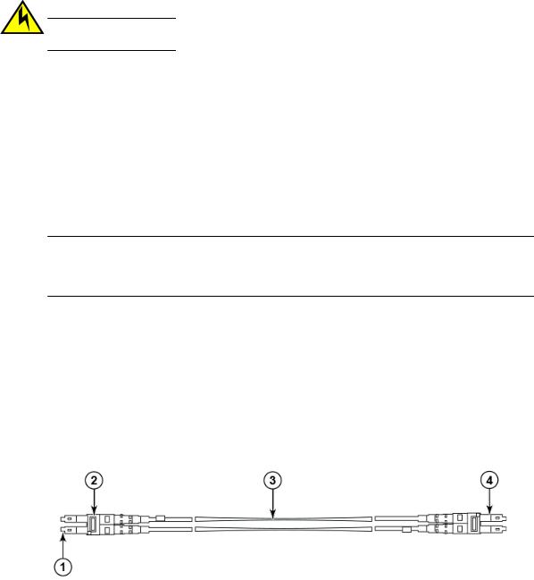
The FC8-64 high density port blade cannot use the standard LC cables because the pitch between optics in the new mini-SFP (mSFP) transceiver is smaller than in standard SFPs. Patch cables and panels can be used to attach standard size cabling to the blade if necessary. The following figure illustrates the mSFP to SFP patch cable. Refer to "Best Practices Guide: High Density Cable Management Solutions" (available at http://www.brocade.com ) for cable management guidelines for high-density port solutions, and cable and patch panel part numbers.
FIGURE 3 Cable design for the mSFP patch cables for the FC8-64 high density port blade
1.mSFP connector
2.Duplex clip (black)
3.6 mm cable
4.SFP connector
Note that the duplex clip on the mSFP end of the cable is black for easier recognition. Refer to Qualified cables for the FC8-64 port blade on page 138 for a listing of the qualified mSFP optical cables for the FC8-64 port blade.
If ISL Trunking is in use, group the cables by trunking group. The ports are color-coded to indicate which ports can be used in the same ISL Trunking group: eight ports marked with solid black ovals alternate with eight ports marked with oval outlines.
30 |
Brocade DCX 8510-8 Backbone Hardware Reference Manual |
|
53-1002180-07 |
Loading...