


 Loading...
53-1003084-01 |
® |
08 January 2014 |
|
Brocade ICX 7750
Hardware Installation Guide
Supporting FastIron Software Release 08.0.10
Copyright © 2014 Brocade Communications Systems, Inc. All Rights Reserved.
ADX, AnyIO, Brocade, Brocade Assurance, the B-wing symbol, DCX, Fabric OS, ICX, MLX, MyBrocade, OpenScript, VCS, VDX, and Vyatta are registered trademarks, and HyperEdge, The Effortless Network, and The On-Demand Data Center are trademarks of Brocade Communications Systems, Inc., in the United States and/or in other countries. Other brands, products, or service names mentioned may be trademarks of their respective owners.
Notice: This document is for informational purposes only and does not set forth any warranty, expressed or implied, concerning any equipment, equipment feature, or service offered or to be offered by Brocade. Brocade reserves the right to make changes to this document at any time, without notice, and assumes no responsibility for its use. This informational document describes features that may not be currently available. Contact a Brocade sales office for information on feature and product availability. Export of technical data contained in this document may require an export license from the United States government.
The authors and Brocade Communications Systems, Inc. shall have no liability or responsibility to any person or entity with respect to any loss, cost, liability, or damages arising from the information contained in this book or the computer programs that accompany it.
The product described by this document may contain “open source” software covered by the GNU General Public License or other open source license agreements. To find out which open source software is included in Brocade products, view the licensing terms applicable to the open source software, and obtain a copy of the programming source code, please visit http://www.brocade.com/support/oscd.
Brocade Communications Systems, Incorporated
Corporate and Latin American Headquarters |
Asia-Pacific Headquarters |
|
|
Brocade Communications Systems, Inc. |
Brocade Communications Systems China HK, Ltd. |
||
130 Holger Way |
No. 1 Guanghua Road |
|
|
San Jose, CA 95134 |
Chao Yang District |
|
|
Tel: 1-408-333-8000 |
Units 2718 and 2818 |
|
|
Fax: 1-408-333-8101 |
Beijing 100020, China |
|
|
E-mail: info@brocade.com |
Tel: +8610 6588 8888 |
|
|
|
Fax: +8610 6588 9999 |
|
|
|
E-mail: china-info@brocade.com |
|
|
European Headquarters |
Asia-Pacific Headquarters |
|
|
Brocade Communications Switzerland Sàrl |
Brocade Communications Systems Co., Ltd. (Shenzhen WFOE) |
||
Centre Swissair |
Citic Plaza |
|
|
Tour B - 4ème étage |
No. 233 Tian He Road North |
|
|
29, Route de l'Aéroport |
Unit 1308 – 13th Floor |
|
|
Case Postale 105 |
Guangzhou, China |
|
|
CH-1215 Genève 15 |
Tel: +8620 3891 2000 |
|
|
Switzerland |
Fax: +8620 3891 2111 |
|
|
Tel: +41 22 799 5640 |
E-mail: china-info@brocade.com |
|
|
Fax: +41 22 799 5641 |
|
|
|
E-mail: emea-info@brocade.com |
|
|
|
Document History |
|
|
|
|
|
|
|
Title |
Publication number |
Summary of changes |
Date |
|
|
|
|
Brocade ICX 7750 Hardware Installation |
53-1003084-01 |
Initial Release |
January 2014 |
Guide |
|
|
|
|
|
|
|

Contents
About This Guide
Audience . . . . . . . . . . . . . . . . . . . . . . . . . . . . . . . . . . . . . . . . . . . . . . . vii Supported hardware and software . . . . . . . . . . . . . . . . . . . . . . . . . . vii How this document is organized . . . . . . . . . . . . . . . . . . . . . . . . . . . . vii
Document conventions. . . . . . . . . . . . . . . . . . . . . . . . . . . . . . . . . . . . viii Text formatting . . . . . . . . . . . . . . . . . . . . . . . . . . . . . . . . . . . . . . . viii Command syntax conventions . . . . . . . . . . . . . . . . . . . . . . . . . . viii Notes, cautions, and danger notices . . . . . . . . . . . . . . . . . . . . . viii
Notice to the reader . . . . . . . . . . . . . . . . . . . . . . . . . . . . . . . . . . . . . . . ix Related publications . . . . . . . . . . . . . . . . . . . . . . . . . . . . . . . . . . . . . . . ix
Additional information. . . . . . . . . . . . . . . . . . . . . . . . . . . . . . . . . . . . . . x Brocade resources. . . . . . . . . . . . . . . . . . . . . . . . . . . . . . . . . . . . . x
Getting technical help. . . . . . . . . . . . . . . . . . . . . . . . . . . . . . . . . . . . . . x Document feedback . . . . . . . . . . . . . . . . . . . . . . . . . . . . . . . . . . . . . . . x
Chapter 1 |
Brocade ICX 7750 Overview |
|
|
In this chapter . . . . . . . . . . . . . . . . . . . . . . . . . . . . . . . . . . . . . . . . . . . . |
1 |
Brocade ICX 7750 features . . . . . . . . . . . . . . . . . . . . . . . . . . . . . . . . . 1 Brocade ICX 7750 orderable models . . . . . . . . . . . . . . . . . . . . . . 2 Brocade ICX 7750 customizable models . . . . . . . . . . . . . . . . . . . 2
Views of the Brocade ICX 7750 switch . . . . . . . . . . . . . . . . . . . . . . . . 3 Brocade ICX 7750 slot and Ethernet port numbering . . . . . . . . . . . . 5 Supported expansion module . . . . . . . . . . . . . . . . . . . . . . . . . . . . . . . 6 Supported transceivers and cables . . . . . . . . . . . . . . . . . . . . . . . . . . . 7
Chapter 2 |
Installing the Brocade ICX 7750 |
|
|
Unpacking the device . . . . . . . . . . . . . . . . . . . . . . . . . . . . . . . . . . . . . |
. 9 |
|
Installation and safety considerations. . . . . . . . . . . . . . . . . . . . . . . . |
10 |
|
Electrical considerations . . . . . . . . . . . . . . . . . . . . . . . . . . . . . . . |
10 |
|
Environmental considerations . . . . . . . . . . . . . . . . . . . . . . . . . . |
10 |
|
Location considerations . . . . . . . . . . . . . . . . . . . . . . . . . . . . . . . |
10 |
|
Cabinet considerations . . . . . . . . . . . . . . . . . . . . . . . . . . . . . . . . |
11 |
|
Recommendations for cable management . . . . . . . . . . . . . . . . |
11 |
Installation tasks. . . . . . . . . . . . . . . . . . . . . . . . . . . . . . . . . . . . . . . . .12
Brocade ICX 7750 Hardware Installation Guide |
iii |
53-1003084-01 |
|
Installation precautions . . . . . . . . . . . . . . . . . . . . . . . . . . . . . . . . . . .13 General precautions . . . . . . . . . . . . . . . . . . . . . . . . . . . . . . . . . .13 Lifting precautions . . . . . . . . . . . . . . . . . . . . . . . . . . . . . . . . . . . .13 Power precautions . . . . . . . . . . . . . . . . . . . . . . . . . . . . . . . . . . . . 14
Installing the device in a rack or cabinet. . . . . . . . . . . . . . . . . . . . . . 14 2-post rack mount installation . . . . . . . . . . . . . . . . . . . . . . . . . .15 4-post rack mount installation . . . . . . . . . . . . . . . . . . . . . . . . . . 17
Grounding the system. . . . . . . . . . . . . . . . . . . . . . . . . . . . . . . . . . . . .18 Powering on the system . . . . . . . . . . . . . . . . . . . . . . . . . . . . . . . . . . . 18
Power supplies . . . . . . . . . . . . . . . . . . . . . . . . . . . . . . . . . . . . . . . . . . 19 Installing and replacing a power supply unit . . . . . . . . . . . . . . .19 Installing an AC power supply . . . . . . . . . . . . . . . . . . . . . . . . . . .19 Installing a DC power supply . . . . . . . . . . . . . . . . . . . . . . . . . . . .20 DC-DC power source cautions. . . . . . . . . . . . . . . . . . . . . . . . . . .22
Attaching a PC or terminal . . . . . . . . . . . . . . . . . . . . . . . . . . . . . . . . .23 Connecting to the management port. . . . . . . . . . . . . . . . . . . . . . . . .23 Installing an SFP+ transceiver . . . . . . . . . . . . . . . . . . . . . . . . . . . . . . 24
Chapter 3 |
Brocade ICX 7750 Operation |
|
|
LED activity interpretation . . . . . . . . . . . . . . . . . . . . . . . . . . . . . . . . . |
25 |
|
Brocade ICX 7750 front panel LEDs . . . . . . . . . . . . . . . . . . . . . . . . . |
25 |
Brocade ICX 7750 rear panel LEDs . . . . . . . . . . . . . . . . . . . . . . . . . .28 LED patterns . . . . . . . . . . . . . . . . . . . . . . . . . . . . . . . . . . . . . . . . . . . .29 Diagnostic tests and monitoring . . . . . . . . . . . . . . . . . . . . . . . . . . . .32
Chapter 4 |
Managing the Brocade ICX 7750 |
|
|
Hardware maintenance schedule . . . . . . . . . . . . . . . . . . . . . . . . . . . |
35 |
Replacing a copper or fiber-optic module . . . . . . . . . . . . . . . . . . . . .35 Removing a copper or fiber-optic module . . . . . . . . . . . . . . . . .36 Cabling a fiber-optic module . . . . . . . . . . . . . . . . . . . . . . . . . . . .36 Cleaning the fiber-optic connectors . . . . . . . . . . . . . . . . . . . . . . 37
FRU removal and replacement procedures. . . . . . . . . . . . . . . . . . . . 37
Replacing a power supply unit . . . . . . . . . . . . . . . . . . . . . . . . . . . . . .38 Determining the need to replace a power supply . . . . . . . . . . .38 Time and items required . . . . . . . . . . . . . . . . . . . . . . . . . . . . . . .39 Replacing a power supply . . . . . . . . . . . . . . . . . . . . . . . . . . . . . .39
Replacing fan trays . . . . . . . . . . . . . . . . . . . . . . . . . . . . . . . . . . . . . . .40 Determining the need to replace a fan assembly . . . . . . . . . . .40 Time and items required . . . . . . . . . . . . . . . . . . . . . . . . . . . . . . .40 Installing or replacing the fan assembly . . . . . . . . . . . . . . . . . . 41
Replacing an expansion module . . . . . . . . . . . . . . . . . . . . . . . . . . . . 41 Time and items required . . . . . . . . . . . . . . . . . . . . . . . . . . . . . . .42 Installing or replacing an expansion module . . . . . . . . . . . . . . .42
iv |
Brocade ICX 7750 Hardware Installation Guide |
|
53-1003084-01 |
Appendix A |
Brocade ICX 7750 Specifications |
|
|
In this appendix. . . . . . . . . . . . . . . . . . . . . . . . . . . . . . . . . . . . . . . . . . |
45 |
|
Weight and physical dimensions . . . . . . . . . . . . . . . . . . . . . . . . . . . . |
45 |
|
Environmental considerations . . . . . . . . . . . . . . . . . . . . . . . . . . . . . . |
46 |
|
Cooling system and fans. . . . . . . . . . . . . . . . . . . . . . . . . . . . . . . . . . . |
47 |
|
Power supply specifications . . . . . . . . . . . . . . . . . . . . . . . . . . . . . . . . |
49 |
|
General specifications . . . . . . . . . . . . . . . . . . . . . . . . . . . . . . . . . . . . |
50 |
|
Supported media types . . . . . . . . . . . . . . . . . . . . . . . . . . . . . . . . . . . |
50 |
|
Pinouts and signaling . . . . . . . . . . . . . . . . . . . . . . . . . . . . . . . . . . . . . |
51 |
|
Memory specifications . . . . . . . . . . . . . . . . . . . . . . . . . . . . . . . . . . . . |
51 |
Appendix B |
Brocade ICX 7750 Regulatory Statements |
|
|
In this appendix. . . . . . . . . . . . . . . . . . . . . . . . . . . . . . . . . . . . . . . . . . |
53 |
|
USA (FCC CFR 47 Part 15 Warning) . . . . . . . . . . . . . . . . . . . . . . . . . . |
53 |
|
Industry Canada statement . . . . . . . . . . . . . . . . . . . . . . . . . . . . . . . . |
53 |
|
Europe and Australia (CISPR 22 Class A Warning) . . . . . . . . . . . . . . |
54 |
|
Germany (Noise Warning). . . . . . . . . . . . . . . . . . . . . . . . . . . . . . . . . . |
54 |
|
Japan (VCCI). . . . . . . . . . . . . . . . . . . . . . . . . . . . . . . . . . . . . . . . . . . . . |
54 |
|
Japan power cord . . . . . . . . . . . . . . . . . . . . . . . . . . . . . . . . . . . . . . . . |
54 |
|
Korea . . . . . . . . . . . . . . . . . . . . . . . . . . . . . . . . . . . . . . . . . . . . . . . . . . |
55 |
|
China . . . . . . . . . . . . . . . . . . . . . . . . . . . . . . . . . . . . . . . . . . . . . . . . . . |
55 |
|
BSMI statement (Taiwan) . . . . . . . . . . . . . . . . . . . . . . . . . . . . . . . . . . |
56 |
|
Regulatory compliance . . . . . . . . . . . . . . . . . . . . . . . . . . . . . . . . . . . . |
57 |
Appendix C |
Brocade ICX 7750 Cautions and Danger Notices |
|
|
In this appendix. . . . . . . . . . . . . . . . . . . . . . . . . . . . . . . . . . . . . . . . . . |
59 |
|
Cautions. . . . . . . . . . . . . . . . . . . . . . . . . . . . . . . . . . . . . . . . . . . . . . . . |
59 |
|
Danger Notices . . . . . . . . . . . . . . . . . . . . . . . . . . . . . . . . . . . . . . . . . . |
64 |
Index |
|
|
Brocade ICX 7750 Hardware Installation Guide |
v |
53-1003084-01 |
|
vi |
Brocade ICX 7750 Hardware Installation Guide |
|
53-1003084-01 |

About This Guide
The Brocade ICX 7750 are Ethernet switches for campus LAN aggregation and classic Ethernet data center Top-of-Rack (ToR) environments.
Audience
This document is designed for system administrators with a working knowledge of Layer 2 and Layer 3 switching and routing.
If you are using a Brocade Layer 3 Switch, you should be familiar with the following protocols if applicable to your network: IP, RIP, OSPF, BGP, ISIS, PIM, and VRRP.
Supported hardware and software
This document is specific to the Brocade ICX 7750 running FastIron release 08.0.10.
How this document is organized
The document contains the following components:
•Chapter 1, “Brocade ICX 7750 Overview” provides an overview of the Brocade ICX 7750.
•Chapter 2, “Installing the Brocade ICX 7750” provides the information needed to install the switch in your network.
•Chapter 3, “Brocade ICX 7750 Operation” discusses the day-to-day operational procedures for using the switch.
•Chapter 4, “Managing the Brocade ICX 7750” provides procedures for removing and replacing the field-replaceable units (FRUs), including the fan assemblies and power supplies.
•Appendix A, “Brocade ICX 7750 Specifications” provides tables of physical, environmental, and general specifications.
•Appendix B, “Brocade ICX 7750 Regulatory Statements” provides a list of the regulatory statements for safety compliance.
•Appendix C, “Brocade ICX 7750 Cautions and Danger Notices” provides a list of the international caution and danger statements for safety compliance.
Brocade ICX 7750 Hardware Installation Guide |
vii |
53-1003084-01 |
|
Document conventions
This section describes text formatting conventions and important notice formats used in this document.
Text formatting
The narrative-text formatting conventions that are used are as follows:
bold text |
Identifies command names |
|
Identifies the names of user-manipulated GUI elements |
|
Identifies keywords |
|
Identifies text to enter at the GUI or CLI |
italic text |
Provides emphasis |
|
Identifies variables |
|
Identifies paths and Internet addresses |
|
Identifies document titles |
code text |
Identifies CLI output |
For readability, command names in the narrative portions of this guide are presented in mixed lettercase: for example, switchShow. In actual examples, command lettercase is all lowercase.
Command syntax conventions
Command syntax in this manual follows these conventions:
command |
Commands are printed in bold. |
--option, option |
Command options are printed in bold. |
-argument, arg |
Arguments. |
[ ] |
Optional elements appear in brackets. |
variable |
Variables are printed in italics. In the help pages, values are underlined or |
|
enclosed in angled brackets < >. |
... |
Repeat the previous element, for example “member[;member...]” |
value |
Fixed values following arguments are printed in plain font. For example, |
|
--show WWN |
| |
Boolean. Elements are exclusive. Example: --show -mode egress | ingress |
Notes, cautions, and danger notices
The following notices and statements are used in this manual. They are listed below in order of increasing severity of potential hazards.
viii |
Brocade ICX 7750 Hardware Installation Guide |
|
53-1003084-01 |

NOTE
A note provides a tip, guidance, or advice, emphasizes important information, or provides a reference to related information.
ATTENTION
An Attention statement indicates potential damage to hardware or data.
CAUTION
A Caution statement alerts you to situations that can be potentially hazardous to you or cause damage to hardware, firmware, software, or data.
DANGER
A Danger statement indicates conditions or situations that can be potentially lethal or extremely hazardous to you. Safety labels are also attached directly to products to warn of these conditions or situations.
Notice to the reader
This document might contain references to the trademarks of the following corporations. These trademarks are the properties of their respective companies and corporations.
These references are made for informational purposes only.
Corporation |
Referenced Trademarks and Products |
|
|
Microsoft Corporation |
Windows, Windows NT, Internet Explorer |
|
|
Oracle Corporation |
Oracle, Java |
|
|
Netscape Communications Corporation |
Netscape |
|
|
Mozilla Corporation |
Mozilla Firefox |
|
|
Sun Microsystems, Inc |
Sun, Solaris |
|
|
Red Hat, Inc. |
Red Hat, Red Hat Network, Maximum RPM, Linux Undercover |
|
|
Related publications
The following Brocade documents supplement the information in this guide:
•Brocade ICX 7750 Release Notes
•Brocade ICX 7750 Administration Guide
•Brocade ICX 7750 Platform and Layer 2 Configuration Guide
•Brocade ICX 7750 Layer 3 Routing Configuration Guide
Brocade ICX 7750 Hardware Installation Guide |
ix |
53-1003084-01 |
|
•Brocade ICX 7750 Security Configuration Guide
•Brocade ICX 7750 IP Multicast Configuration Guide
•Brocade ICX 7750 Diagnostic Reference
•Unified IP MIB Reference
The latest versions of these guides are posted at http://www.myBrocade.com/ethernetproducts.
Additional information
This section lists additional Brocade and industry-specific documentation that you might find helpful.
Brocade resources
To get up-to-the-minute information, go to http://www.myBrocade.com to register at no cost for a user ID and password.
White papers, online demonstrations, and data sheets are available through the Brocade website at:
http://www.myBrocade.com/products-solutions/products/index.page For additional Brocade documentation, visit the Brocade website:
http://www.myBrocade.com
Release notes are available on the MyBrocade website.
Getting technical help
To contact Technical Support, go to http://www.myBrocade.com/services-support/index.page
for the latest e-mail and telephone contact information.
Document feedback
Quality is our first concern at Brocade and we have made every effort to ensure the accuracy and completeness of this document. However, if you find an error or an omission, or you think that a topic needs further development, we want to hear from you. Forward your feedback to:
documentation@brocade.com
Provide the title and version number of the document and as much detail as possible about your comment, including the topic heading and page number and your suggestions for improvement.
x |
Brocade ICX 7750 Hardware Installation Guide |
|
53-1003084-01 |
|
Chapter |
|
Brocade ICX 7750 Overview |
1 |
|
|
|
|
In this chapter
•Brocade ICX 7750 features . . . . . . . . . . . . . . . . . . . . . . . . . . . . . . . . . . . . . . . |
1 |
•Views of the Brocade ICX 7750 switch . . . . . . . . . . . . . . . . . . . . . . . . . . . . . . |
3 |
•Brocade ICX 7750 slot and Ethernet port numbering . . . . . . . . . . . . . . . . . . |
5 |
•Supported expansion module. . . . . . . . . . . . . . . . . . . . . . . . . . . . . . . . . . . . . . |
6 |
•Supported transceivers and cables . . . . . . . . . . . . . . . . . . . . . . . . . . . . . . . . . |
7 |
Brocade ICX 7750 features
The Brocade ICX 7750 are high-density aggregation switches that offer both 1/10 and 10/40 Gigabit Ethernet (GbE) line rates, low latency cut-through switching, and up to 2.56 Tbps throughput for campus LAN and classic Ethernet data center environments.
The Brocade ICX 7750 switches feature:
•Comprehensive support for a range of 1 GbE, 10 GbE, and 40 GbE optics (refer to the Brocade Optics Family Data Sheet).
•Dual redundant, hot-swappable 504 W AC or DC power supplies available with intake or exhaust airflow.
•Optional hot-swappable 6-port 10/40 GbE QSFP+ expansion module.
•Four redundant, hot-swappable fan units available with intake or exhaust airflow.
•One Gigabit Ethernet port (RJ-45) and one serial management port (mini-USB) to configure and manage the switch through the CLI.
•One USB port for the transfer of software and configuration files from an external disk drive.
•Two high-availability (HA) ports that enable up to 32 switches to be connected together to form a CPU cluster within the stack.
Brocade ICX 7750 Hardware Installation Guide |
1 |
53-1003084-01 |
|
1 Brocade ICX 7750 features
Brocade ICX 7750 orderable models
The Brocade ICX 7750 switches consist of these orderable models:
TABLE 1 Brocade ICX 7750 orderable switch models
Model |
Description |
|
|
|
|
ICX 7750-26Q |
Brocade ICX 7750 with 26 |
10/40 GbE QSFP+ ports. No power supplies, fan units, or |
|
expansion module (need to be ordered separately). Advanced software. No optics. |
|
|
|
|
ICX 7750-48F |
Brocade ICX 7750 with 48 |
1/10 GbE SFP+ ports and six 10/40 GbE QSFP+ ports. No |
|
power supplies, fan units, or expansion module (need to be ordered separately). |
|
|
Advanced software. No optics. |
|
|
|
|
ICX 7750-48C |
Brocade ICX 7750 with 48 |
1/10 GbE RJ-45 ports and six 10/40 GbE QSFP+ ports. No |
|
power supplies, fan units, or expansion module (need to be ordered separately). |
|
|
Advanced software. No optics. |
|
|
|
|
Brocade ICX 7750 customizable models
The Brocade ICX 7750 base systems do not ship with power supplies or fans, these are ordered separately to allow for building the system that meets your network needs. Table 2 lists the available power supplies, fans, and the optional module.
TABLE 2 |
SKUs for creating custom Brocade ICX 7750 switch models |
||
|
|
|
|
Model |
|
Description |
|
|
|
|
|
RPS9+E |
|
504 |
W AC power supply; power-supply-side exhaust (port-side intake) airflow. |
|
|
|
|
RPS9+I |
|
504 |
W AC power supply; power-supply-side intake (port-side exhaust) airflow. |
|
|
|
|
RPS9DC+E |
|
504 |
W DC power supply; power-supply-side exhaust (port-side intake) airflow. |
|
|
|
|
RPS9DC+I |
|
504 |
W DC power supply; power-supply-side intake (port-side exhaust) airflow. |
|
|
||
ICX 7750-FAN-E |
Brocade ICX 7750 fan kit of 4, exhaust airflow. |
||
|
|
||
ICX 7750-FAN-I |
Brocade ICX 7750 fan kit of 4, intake airflow. |
||
|
|
||
ICX 7750-FAN-E-SINGLE |
Brocade ICX 7750 fan, exhaust airflow. |
||
|
|
||
ICX 7750-FAN-I-SINGLE |
Brocade ICX 7750 fan, intake airflow. |
||
|
|
|
|
ICX 7750-6Q |
|
Brocade ICX 7750 6-port QSFP+ expansion module. |
|
|
|
|
|
2 |
Brocade ICX 7750 Hardware Installation Guide |
|
53-1003084-01 |
Views of the Brocade ICX 7750 switch |
1 |
Views of the Brocade ICX 7750 switch
Figure 1 shows the front view of the Brocade ICX 7750-26Q switch.
FIGURE 1 Front view of the Brocade ICX 7750-26Q
1 |
QSFP+ ports XL1/1 - XL1/20 and XL2/1 - XL2/6 |
4 |
Console port |
2 |
System LEDs |
5 |
Reset button |
3 |
Stack unit ID display |
6 |
QSFP+ port LEDs |
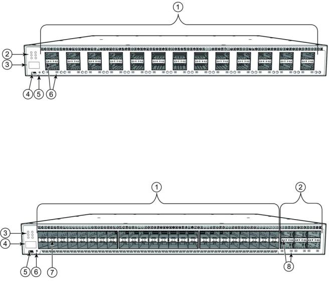
Figure 2 shows the front view of the Brocade ICX 7750-48F switch.
FIGURE 2 Front view of the Brocade ICX 7750-48F
1 |
SFP+ ports 1/1 - 1/48 |
5 |
Console port |
2 |
QSFP+ ports XL2/1 - XL2/6 |
6 |
Reset button |
3 |
System LEDs |
7 |
SFP+ port LEDs |
4 |
Stack unit ID display |
8 |
QSFP+ port LEDs |
Brocade ICX 7750 Hardware Installation Guide |
3 |
53-1003084-01 |
|

1 Views of the Brocade ICX 7750 switch
Figure 3 shows the front view of the Brocade ICX 7750-48C switch.
Front view of the Brocade ICX 7750-48C
1 |
10GBase-T RJ-45 ports 1/1 - 1/48 |
5 |
Console port |
2 |
QSFP+ ports XL2/1 - XL2/6 |
6 |
Reset button |
3 |
System LEDs |
7 |
10GBase-T port LEDs |
4 |
Stack unit ID display |
8 |
QSFP+ port LEDs |
Figure 4 shows the rear view of the Brocade ICX 7750 switch.
Rear view of the Brocade ICX 7750
1 |
Power supply unit 2 |
9 |
Fan tray 3 |
2 |
Fan tray LED |
10 |
HA port LEDs |
3 |
Management port |
11 |
HA ports |
4 |
USB port |
12 |
QSFP+ module LEDs |
5 |
6-port 10/40G QSFP+ expansion module |
13 |
Expansion module power LED |
6 |
Power supply unit 1 |
14 |
Fan tray 2 |
7 |
Power supply unit 2 LED |
15 |
Fan tray 1 |
8 |
Fan tray 4 |
|
|
4 |
Brocade ICX 7750 Hardware Installation Guide |
|
53-1003084-01 |

Brocade ICX 7750 slot and Ethernet port numbering |
1 |
Brocade ICX 7750 slot and Ethernet port numbering
Many CLI commands require users to enter port numbers as part of the command syntax, and many show command outputs display port numbers. The port numbers are entered and displayed in stack-unit/slot number/port number format.
The Brocade ICX 7750 contains the following slots and Ethernet ports:
•Slot 1 and Slot 2 are located on the front of the Brocade ICX 7750-26Q device. Slot 1 contains 10/40 GbE QSFP+ ports XL1/1 through XL1/20; odd port numbers on the top row with port XL1/1 on the left and port XL1/19 on the right. Slot 2 contains 10/40 GbE QSFP+ ports XL2/1 through XL2/6; ports XL2/1, XL2/3, and XL2/5 are on the top row (left to right), and ports XL2/2, XL2/4, and XL2/6 are on the bottom row (left to right). Refer to the following figure.
FIGURE 5 Brocade ICX 7750-26Q slot numbering
•Slot 1 and Slot 2 are located on the front of the Brocade ICX 7750-48F device. Slot 1 contains 1/10 GbE SFP+ ports 1/1 through 1/48, with odd port numbers on the top row and port 1/1 on the left. Slot 2 contains 10/40 GbE QSFP+ ports XL2/1, XL2/3, and XL2/5 on the top row (left to right), and ports XL2/2, XL2/4, and XL2/6 on the bottom row (left to right). Refer to the following figure.
FIGURE 6 Brocade ICX 7750-48F slot numbering
•Slot 1 and Slot 2 are located on the front of the Brocade ICX 7750-48C device. Slot 1 contains 1/10 GbE RJ-45 ports 1/1 through 1/48, with odd port numbers on the top row and port 1/1 on the left. Slot 2 contains 10/40 GbE QSFP+ ports XL2/1, XL2/3, and XL2/5 on the top row (left to right), and ports XL2/2, XL2/4, and XL2/6 on the bottom row (left to right). Refer to the following figure.
Brocade ICX 7750 Hardware Installation Guide |
5 |
53-1003084-01 |
|

1 Supported expansion module
FIGURE 7 Brocade ICX 7750-48C slot numbering
•Slot 3 is located on the rear of the Brocade ICX 7750 switches and contains ports XL3/1, XL3/3, and XL3/5 on the top row (left to right) and ports XL3/2, XL3/4, and XL3/6 on the bottom row (left to right). These ports are 10/40 GbE QSFP+ ports. Refer to the following figure.
FIGURE 8 Brocade ICX 7750 rear slot numbering
Supported expansion module
A 6-port 10/40 GbE QSFP+ expansion module can be purchased and installed in the rear of the Brocade ICX 7750. The expansion module is hot-swappable and supports a range of 10 GbE and 40 GbE optics (refer to the Brocade Optics Family Data Sheet).
6 |
Brocade ICX 7750 Hardware Installation Guide |
|
53-1003084-01 |

Supported transceivers and cables |
1 |
Instructions for installing or replacing an expansion module are described in “Replacing an expansion module” on page 41.
FIGURE 9 10/40 GbE QSFP+ expansion module
|
|
|
|
|
1 |
Assembly screws |
3 |
Expansion module power LED |
|
2 |
Release lever latch |
4 |
QSFP+ slot LEDs |
|
Supported transceivers and cables
For a list of supported transceivers and cables, refer to the Brocade Optics Family Data Sheet.
Brocade ICX 7750 Hardware Installation Guide |
7 |
53-1003084-01 |
|
1 Supported transceivers and cables
8 |
Brocade ICX 7750 Hardware Installation Guide |
|
53-1003084-01 |

|
Chapter |
|
Installing the Brocade ICX 7750 |
2 |
|
|
|
|
This chapter includes these sections:
•Unpacking the device . . . . . . . . . . . . . . . . . . . . . . . . . . . . . . . . . . . . . . . . . . . . 9
•Installation and safety considerations . . . . . . . . . . . . . . . . . . . . . . . . . . . . . . 10
•Installation tasks . . . . . . . . . . . . . . . . . . . . . . . . . . . . . . . . . . . . . . . . . . . . . . . 12
•Installation precautions . . . . . . . . . . . . . . . . . . . . . . . . . . . . . . . . . . . . . . . . . 13
•Installing the device in a rack or cabinet . . . . . . . . . . . . . . . . . . . . . . . . . . . . 14
•Grounding the system . . . . . . . . . . . . . . . . . . . . . . . . . . . . . . . . . . . . . . . . . . . 18
•Powering on the system . . . . . . . . . . . . . . . . . . . . . . . . . . . . . . . . . . . . . . . . . 18
•Power supplies. . . . . . . . . . . . . . . . . . . . . . . . . . . . . . . . . . . . . . . . . . . . . . . . . 19
•Attaching a PC or terminal . . . . . . . . . . . . . . . . . . . . . . . . . . . . . . . . . . . . . . . 23
•Connecting to the management port . . . . . . . . . . . . . . . . . . . . . . . . . . . . . . . 23
•Installing an SFP+ transceiver . . . . . . . . . . . . . . . . . . . . . . . . . . . . . . . . . . . . 24
CAUTION
Procedures in this manual are intended for qualified service personnel.
CAUTION
Before beginning the installation, see the precautions in “Power precautions” on page 14“.
Unpacking the device
The Brocade ICX 7750 ships with all of the items listed below. Verify the contents of your shipping container. If any items are missing, contact the place of purchase.
The following items are included in your shipping carton:
•A Brocade ICX 7750 switch
•One accessory kit, containing two mounting ears and eight screws
•One console cable (Mini-USB to RJ-45)
•Two Micro-HDMI to RJ-45 HA cables
•One HA cable holder kit, containing one HA cable holder and one screw
•One grounding kit, containing one grounding lug and one grounding screw
•Installed filler panels for the PSU 2 slot, expansion module slot, and fan tray slot 1
Brocade ICX 7750 Hardware Installation Guide |
9 |
53-1003084-01 |
|

2 Installation and safety considerations
NOTE
The HA cables and HA cable holder kit should be stored in a safe place for future use when the stacking feature is available.
Installation and safety considerations
You can install the Brocade ICX 7750 in the following ways:
•As a standalone unit on a flat surface.
•In an EIA cabinet using a fixed-rail rack mount kit. The optional 4-post universal rack mount kit can be order from your switch retailer to support up to a 30" deep rack. The 4-post rack mount kit includes mid-mount and rear-mount brackets.
•In a 2-post Telco rack using a flush-mount rack kit. The 2-post rack mount ears are included with the switch and support various mounting positions (refer to Figure 10).
Electrical considerations
To install and operate the switch successfully, ensure compliance with the following requirements:
•The primary outlet is correctly wired, protected by a circuit breaker, and grounded in accordance with local electrical codes.
•The supply circuit, line fusing, and wire size are adequate, as specified by the electrical rating on the switch nameplate.
•The power supply standards are met.
Environmental considerations
For successful installation and operation of the switch, ensure that the following environmental requirements are met:
•Because the Brocade ICX 7750 can be ordered with fans that move air either front to back or back to front, be sure to orient your switch with the airflow pattern of any other devices in the rack. All equipment in the rack should force air in the same direction to avoid intake of exhaust air.
•Some combinations of intake and exhaust airflows may not be compatible with your environment. Consult your fan and power supply module FRU kit to determine the correct configuration.
•The ambient air temperature does not exceed 50°C (122°F) while the Brocade ICX 7750-26Q or Brocade ICX 7750-48F switch is operating, or 40°C (104°F) while the Brocade ICX 7750-48C switch is operating.
Location considerations
Before installing the device, plan its location and orientation relative to other devices and equipment. Devices can be mounted in a standard 19-inch equipment rack or on a flat surface.
10 |
Brocade ICX 7750 Hardware Installation Guide |
|
53-1003084-01 |
Installation and safety considerations |
2 |
The site should meet the following requirements:
•Maintain the operating environment as specified in “Environmental considerations” on page 10.
•The ICX 7750 should be installed with its top/bottom covers parallel to the floor. The ICX 7750 should not be installed upside down.
•Allow a minimum of 3 in. of space between the front and the back of the device and walls or other obstructions for proper airflow.
•Allow at least 3 in. of space at the front and back of the device for the twisted-pair, fiber-optic, and power cabling.
•Allow access for installing, cabling, and maintaining the devices.
•Allow the status LEDs to be clearly visible.
•Allow for twisted-pair cables to be routed away from power lines, fluorescent lighting fixtures, and other sources of electrical interference, such as radios and transmitters.
•Allow for the unit to be connected to a separate grounded power outlet that provides 100 to 240 VAC, 50 to 60 Hz, is within 2 m (6.6 ft) of each device, and is powered from an independent circuit breaker. As with any equipment, a filter or surge suppressor is recommended.
Cabinet considerations
For successful installation and operation of the switch in a cabinet, ensure the following cabinet requirements are met:
•The cabinet must be a standard EIA cabinet.
•The equipment in the cabinet is grounded through a reliable branch circuit connection and maintains ground at all times. Do not rely on a secondary connection to a branch circuit, such as a power strip.
•Airflow and temperature requirements are met on an ongoing basis, particularly if the switch is installed in a closed or multicabinet assembly.
•The additional weight of the switch does not exceed the cabinet’s weight limits or unbalance the cabinet in any way.
•The cabinet is secured to ensure stability in case of unexpected movement, such as an earthquake.
Recommendations for cable management
Cables can be organized and managed in a variety of ways; for example, use cable channels on the sides of the cabinet or patch panels to reduce the potential for tangling the cables. The following list provides some recommendations for cable management:
CAUTION
Before plugging a cable to any port, be sure to discharge any static charge stored on the cable by touching the electrical contacts to ground surface.
Brocade ICX 7750 Hardware Installation Guide |
11 |
53-1003084-01 |
|

2 Installation tasks
ATTENTION
You should not use tie wraps with fiber-optic cables because they are easily overtightened and can damage the optical fibers. Velcro-like wraps are recommended.
•Plan for the rack space required for cable management before installing the switch.
•Leave at least 1 m (3.28 ft) of slack for each port cable. This provides room to remove and replace the switch, allows for inadvertent movement of the rack, and helps prevent the cables from being bent to less than the minimum bend radius.
•For easier maintenance, label the cables and record the devices to which they are connected.
•Keep LEDs visible by routing port cables and other cables away from the LEDs.
Installation tasks
Follow the steps listed in Table 3 to install your device. Details for each of these steps are provided on the pages indicated.
TABLE 3 |
Installation tasks |
|
|
|
|
Task |
Task |
Where to find more information |
number |
|
|
|
|
|
1 |
Ensure that the physical environment that will host the device |
“Installation and safety |
|
has the proper cabling and ventilation. |
considerations” on page 10 |
|
|
|
2 |
If customizing a Brocade ICX 7750 baseline chassis: |
“Installing and replacing a power |
|
1 Install at least one power supply unit. |
supply unit” on page 19 |
|
2 Install at least three fans. |
“Installing or replacing the fan |
|
3 Install an expansion module. |
assembly” on page 41 |
|
|
“Installing or replacing an expansion |
|
|
module” on page 42 |
|
|
|
3 |
Install the device in an equipment rack. |
“Installing the device in a rack or |
|
|
cabinet” on page 14 |
|
|
|
4 |
Plug the device into a nearby power source that adheres to the |
“Powering on the system” on page 18 |
|
regulatory requirements outlined in this manual. |
|
|
|
|
5 |
Attach a terminal or PC to the device. This will enable you to |
“Attaching a PC or terminal” on |
|
configure the device through the command line interface (CLI). |
page 23 |
|
|
|
6 |
Assign a password for additional access security. No default |
Brocade ICX 7750 Administration |
|
password is assigned to the CLI. |
Guide |
|
|
|
7 |
Before attaching equipment to the device, you must configure |
Brocade ICX 7750 Administration |
|
an interface IP address to the subnet on which the device will |
Guide |
|
be located. Initial IP address configuration is performed using |
|
|
the CLI with a direct serial connection. |
|
|
|
|
8 |
Connect network equipment to the system. |
|
|
|
|
9 |
Test IP connectivity to other devices by pinging them and |
Brocade ICX 7750 Administration |
|
tracing routes. |
Guide |
|
|
|
10 |
Continue configuring the device using the CLI. |
Brocade ICX 7750 Administration |
|
|
Guide |
|
|
|
11 |
Secure access to the device. |
Brocade ICX 7750 Administration |
|
|
Guide |
|
|
|
12 |
Brocade ICX 7750 Hardware Installation Guide |
|
53-1003084-01 |

Installation precautions |
2 |
Installation precautions
Follow all precautions when installing a device.
General precautions
CAUTION
All fiber-optic interfaces use Class 1 lasers.
CAUTION
Do not install the device in an environment where the operating ambient temperature might exceed 50°C (122°F).
CAUTION
Make sure the airflow around the front and sides of the device is not restricted.
CAUTION
Never leave tools inside the device.
CAUTION
Risk of explosion if battery is replaced by an incorrect type. Dispose of used batteries according to the manufacturer’s instructions.
Lifting precautions
CAUTION
Make sure the rack or cabinet housing the device is adequately secured to prevent it from becoming unstable or falling over.
Brocade ICX 7750 Hardware Installation Guide |
13 |
53-1003084-01 |
|
2 Installing the device in a rack or cabinet
Power precautions
CAUTION
Use a separate branch circuit for each AC power cord, which provides redundancy in case one of the circuits fails.
CAUTION
To avoid high voltage shock, do not open the device while the power is on.
CAUTION
Ensure that the device does not overload the power circuits, wiring, and over-current protection. To determine the possibility of overloading the supply circuits, add the ampere (amp) ratings of all devices installed on the same circuit as the device. Compare this total with the rating limit fo the circuit. The maximum ampere ratings are usually printed on the devices near the input power connectors.
CAUTION
Disconnect the power cord from all power sources to completely remove power from the device.
CAUTION
Before plugging a cable to any port, be sure to discharge any static charge stored on the cable by touching the electrical contacts to ground surface.
CAUTION
If the installation requires a different power cord than the one supplied with the device, make sure you use a power cord displaying the mark of the safety agency that defines the regulations for power cords in your country. The mark is your assurance that the power cord can be used safely with the device.
Installing the device in a rack or cabinet
CAUTION
Make sure the rack or cabinet housing the device is adequately secured to prevent it from becoming unstable or falling over.
14 |
Brocade ICX 7750 Hardware Installation Guide |
|
53-1003084-01 |
Loading...