


7800
Table of contents
 Loading...
53-1001350-05
25 July 2014
Brocade 7800 Extension
Switch
Hardware Reference Manual

©
2014, Brocade Communications Systems, Inc. All Rights Reserved.
Brocade, the B-wing symbol, Brocade Assurance, ADX, AnyIO, DCX, Fabric OS, FastIron, HyperEdge, ICX, MLX, MyBrocade, NetIron,
OpenScript, VCS, VDX, and Vyatta are registered trademarks, and The Effortless Network and the On-Demand Data Center are trademarks
of Brocade Communications Systems, Inc., in the United States and in other countries. Other brands and product names mentioned may be
trademarks of others.
Notice: This document is for informational purposes only and does not set forth any warranty, expressed or implied, concerning any
equipment, equipment feature, or service offered or to be offered by Brocade. Brocade reserves the right to make changes to this document
at any time, without notice, and assumes no responsibility for its use. This informational document describes features that may not be
currently available. Contact a Brocade sales office for information on feature and product availability. Export of technical data contained in
this document may require an export license from the United States government.
The authors and Brocade Communications Systems, Inc. assume no liability or responsibility to any person or entity with respect to the
accuracy of this document or any loss, cost, liability, or damages arising from the information contained herein or the computer programs that
accompany it.
The product described by this document may contain open source software covered by the GNU General Public License or other open
source license agreements. To find out which open source software is included in Brocade products, view the licensing terms applicable to
the open source software, and obtain a copy of the programming source code, please visit http://www.brocade.com/support/oscd.

Contents
Preface.....................................................................................................................................7
Document conventions......................................................................................7
Text formatting conventions.................................................................. 7
Command syntax conventions.............................................................. 7
Notes, cautions, and warnings.............................................................. 8
Brocade resources............................................................................................ 9
Contacting Brocade Technical Support.............................................................9
Document feedback........................................................................................ 10
About this document...............................................................................................................11
Supported hardware and software.................................................................. 11
What’s new in this document.......................................................................... 11
Introducing the Brocade 7800 Extension Switch......................................................................13
Overview of Brocade 7800 Extension Switch................................................. 13
Brocade 7800 Features.......................................................................14
Port side of the Brocade 7800.........................................................................16
Nonport side of the Brocade 7800.................................................................. 17
Brocade 7800 management............................................................................18
Installing and configuring the Brocade 7800........................................................................... 19
Installation and safety considerations............................................................. 19
Installation Precautions................................................................................... 20
General precautions............................................................................20
Power precautions.............................................................................. 20
RTC battery precautions..................................................................... 21
Physical security ................................................................................ 21
Items included with the Brocade 7800 Extension Switch................................21
Setting up the Brocade 7800 Extension Switch as a standalone unit............. 22
Installing in an EIA rack...................................................................................22
Initial setup of the Brocade 7800.....................................................................22
Providing power to the switch............................................................. 23
Creating a serial connection................................................................23
Connecting to the Brocade 7800 using the serial connection............. 24
Setting the switch IP address..............................................................25
Changing the switch name and chassis name....................................25
Creating an Ethernet connection.........................................................26
Setting the Brocade 7800 domain ID.................................................. 26
Setting the Brocade 7800 date and time.............................................26
Synchronizing local time with an external source............................... 27
Correcting the time zone of a Brocade 7800.......................................27
FCIP and Fibre Channel routing services configuration......................28
Installing SFPs and cabling the Brocade 7800................................... 28
Verifying correct operation and backup the configuration................... 29
Recommendations for cable management..................................................... 31
Brocade 7800 Extension Switch Hardware Reference Manual
3
53-1001350-05

Operating the Brocade 7800 Extension Switch...................................................................... 33
LED activity................................................................................................... 33
LEDs on the port side of the Extension Switch................................. 33
LEDs on the nonport side of the Brocade 7800................................ 37
Interpreting POST results..............................................................................37
Brocade 7800 maintenance.......................................................................... 38
Diagnostic tests.................................................................................38
Field replaceable units (FRUs)..........................................................38
Powering off the switch................................................................................. 39
Removal and Replacement of Combined Power Supply and Fan Assembly (Port-side Air
Exhaust).......................................................................................................................... 41
Before beginning installation.........................................................................41
Installing a combined power supply and fan assembly FRU........................ 41
Time required....................................................................................42
Items required................................................................................... 42
Replacing the power supply/fan assembly........................................42
Product specifications.......................................................................................................... 45
Brocade 7800 components........................................................................... 45
Weight and physical dimensions...................................................................45
Facility requirements.....................................................................................46
Power supply specifications..........................................................................46
Environmental requirements......................................................................... 47
Power cords (Japan, Denan)........................................................................ 48
General specifications...................................................................................48
Data transmission ranges............................................................................. 49
Memory specifications...................................................................................50
Fibre Channel port specifications..................................................................50
GbE port specifications................................................................................. 50
Serial port specifications............................................................................... 51
POST and boot specifications.......................................................................51
POST................................................................................................ 51
Boot...................................................................................................52
Federal information processing standards (FIPS)........................................ 52
Regulatory compliance......................................................................................................... 53
FCC warning (US only)................................................................................. 53
KCC statement (Republic of Korea)..............................................................53
VCCI statement.............................................................................................53
Power cords (Japan Denan)......................................................................... 54
China statement............................................................................................55
BSMI statement (Taiwan)..............................................................................56
CE Statement................................................................................................56
Canadian requirements.................................................................................56
Regulatory certifications................................................................................56
Cautions and Danger Notices................................................................................................59
Cautions........................................................................................................59
Danger Notices............................................................................................. 60
4
Brocade 7800 Extension Switch Hardware Reference Manual
53-1001350-05

Index...................................................................................................................................... 65
Brocade 7800 Extension Switch Hardware Reference Manual 5
53-1001350-05

6 Brocade 7800 Extension Switch Hardware Reference Manual
53-1001350-05

Preface
● Document conventions......................................................................................................7
● Brocade resources............................................................................................................ 9
● Contacting Brocade Technical Support.............................................................................9
● Document feedback........................................................................................................ 10
Document conventions
The document conventions describe text formatting conventions, command syntax conventions, and
important notice formats used in Brocade technical documentation.
Text formatting conventions
Text formatting conventions such as boldface, italic, or Courier font may be used in the flow of the text
to highlight specific words or phrases.
Format
Description
bold text
Identifies command names
Identifies keywords and operands
Identifies the names of user-manipulated GUI elements
Identifies text to enter at the GUI
italic text
Identifies emphasis
Identifies variables and modifiers
Identifies paths and Internet addresses
Identifies document titles
Courier font
Identifies CLI output
Identifies command syntax examples
Command syntax conventions
Bold and italic text identify command syntax components. Delimiters and operators define groupings of
parameters and their logical relationships.
Convention
Description
bold text Identifies command names, keywords, and command options.
italic text Identifies a variable.
Brocade 7800 Extension Switch Hardware Reference Manual 7
53-1001350-05

Convention Description
value In Fibre Channel products, a fixed value provided as input to a command
option is printed in plain text, for example, --show WWN.
[ ] Syntax components displayed within square brackets are optional.
Default responses to system prompts are enclosed in square brackets.
{ x | y | z } A choice of required parameters is enclosed in curly brackets separated by
vertical bars. You must select one of the options.
In Fibre Channel products, square brackets may be used instead for this
purpose.
x | y A vertical bar separates mutually exclusive elements.
< > Nonprinting characters, for example, passwords, are enclosed in angle
brackets.
...
Repeat the previous element, for example, member[member...].
\
Indicates a “soft” line break in command examples. If a backslash separates
two lines of a command input, enter the entire command at the prompt without
the backslash.
Notes, cautions, and warnings
Notes, cautions, and warning statements may be used in this document. They are listed in the order of
increasing severity of potential hazards.
NOTE
A Note provides a tip, guidance, or advice, emphasizes important information, or provides a reference
to related information.
ATTENTION
An Attention statement indicates a stronger note, for example, to alert you when traffic might be
interrupted or the device might reboot.
CAUTION
A Caution statement alerts you to situations that can be potentially hazardous to you or cause
damage to hardware, firmware, software, or data.
DANGER
A Danger statement indicates conditions or situations that can be potentially lethal or
extremely hazardous to you. Safety labels are also attached directly to products to warn of
these conditions or situations.
Notes, cautions, and warnings
8 Brocade 7800 Extension Switch Hardware Reference Manual
53-1001350-05

Brocade resources
Visit the Brocade website to locate related documentation for your product and additional Brocade
resources.
You can download additional publications supporting your product at www.brocade.com. Select the
Brocade Products tab to locate your product, then click the Brocade product name or image to open the
individual product page. The user manuals are available in the resources module at the bottom of the
page under the Documentation category.
To get up-to-the-minute information on Brocade products and resources, go to MyBrocade. You can
register at no cost to obtain a user ID and password.
Release notes are available on MyBrocade under Product Downloads.
White papers, online demonstrations, and data sheets are available through the Brocade website.
Contacting Brocade Technical Support
As a Brocade customer, you can contact Brocade Technical Support 24x7 online, by telephone, or by e-
mail. Brocade OEM customers contact their OEM/Solutions provider.
Brocade customers
For product support information and the latest information on contacting the Technical Assistance
Center, go to http://www.brocade.com/services-support/index.html.
If you have purchased Brocade product support directly from Brocade, use one of the following methods
to contact the Brocade Technical Assistance Center 24x7.
Online Telephone E-mail
Preferred method of contact for non-
urgent issues:
• My Cases through MyBrocade
• Software downloads and licensing
tools
• Knowledge Base
Required for Sev 1-Critical and Sev
2-High issues:
• Continental US: 1-800-752-8061
• Europe, Middle East, Africa, and
Asia Pacific: +800-AT FIBREE
(+800 28 34 27 33)
• For areas unable to access toll
free number: +1-408-333-6061
• Toll-free numbers are available in
many countries.
support@brocade.com
Please include:
• Problem summary
• Serial number
• Installation details
• Environment description
Brocade OEM customers
If you have purchased Brocade product support from a Brocade OEM/Solution Provider, contact your
OEM/Solution Provider for all of your product support needs.
• OEM/Solution Providers are trained and certified by Brocade to support Brocade
®
products.
• Brocade provides backline support for issues that cannot be resolved by the OEM/Solution Provider.
Brocade resources
Brocade 7800 Extension Switch Hardware Reference Manual 9
53-1001350-05

• Brocade Supplemental Support augments your existing OEM support contract, providing direct
access to Brocade expertise. For more information, contact Brocade or your OEM.
• For questions regarding service levels and response times, contact your OEM/Solution Provider.
Document feedback
To send feedback and report errors in the documentation you can use the feedback form posted with
the document or you can e-mail the documentation team.
Quality is our first concern at Brocade and we have made every effort to ensure the accuracy and
completeness of this document. However, if you find an error or an omission, or you think that a topic
needs further development, we want to hear from you. You can provide feedback in two ways:
• Through the online feedback form in the HTML documents posted on www.brocade.com.
• By sending your feedback to documentation@brocade.com.
Provide the publication title, part number, and as much detail as possible, including the topic heading
and page number if applicable, as well as your suggestions for improvement.
Document feedback
10 Brocade 7800 Extension Switch Hardware Reference Manual
53-1001350-05

About this document
● Supported hardware and software.................................................................................. 11
● What’s new in this document.......................................................................................... 11
Supported hardware and software
Although many different software and hardware configurations are tested and supported by Brocade
Communications Systems, documenting all possible configurations and scenarios is beyond the scope
of this document.
What’s new in this document
The following changes have bee made in this release of the document.
• Two illustrations indicating the decimal and hexadecimal PIDs of the ports and the port groups are
added.
• A new chapter titled "Removal and Replacement of Combined Power Supply and Fan Assembly
(Port-side Air Exhaust)" has been added to the document.
• All references to EIA cabinet have been changed to EIA rack since closed cabinets are not supported
by Brocade products.
• The regulatory compliance statements are moved to a new chapter/appendix.
‐ The Chinese regulatory statement has been added.
‐ China CCC certification has been updated from “GB17625.1-2003 or latest” to
“GB17625.1-2012 or latest”.
‐ Laser compliance statement is removed.
‐ The Japan VCCI statement has been updated.
‐ China RoHS compliance statements are removed and a reference to the latest independent
China RoHS compliance document is added.
• A new chapter/appendix on cautions and danger notices is added with translation in multiple
languages.
Brocade 7800 Extension Switch Hardware Reference Manual
11
53-1001350-05

What’s new in this document
12 Brocade 7800 Extension Switch Hardware Reference Manual
53-1001350-05

Introducing the Brocade 7800 Extension Switch
● Overview of Brocade 7800 Extension Switch................................................................. 13
● Port side of the Brocade 7800.........................................................................................16
● Nonport side of the Brocade 7800.................................................................................. 17
● Brocade 7800 management............................................................................................18
Overview of Brocade 7800 Extension Switch
The Brocade 7800 Extension Switch is intended as a platform for Fibre Channel over IP (FCIP). This
enables transmission of Fibre Channel data over long distances via IP networks by wrapping Fibre
Channel frames in IP packets. Each end of the FCIP communication path must be a compatible FCIP
device, either the Brocade 7800 or the FX8-24 blade in a DCX-family chassis.
A minimum level of Brocade Fabric Operating System (FOS) 6.3 is required to use the Brocade 7800.
Refer to the Fabric OS Administrator's Guide for information on configuring these features.
The base model of the switch is shipped with six Fibre Channel SFP ports and two physical Gigabit
Ethernet (GbE) ports active. It includes FOS 6.3 and is compatible with the entire Brocade switch family.
It can operate independently or in a fabric containing multiple Extension Switches.
A fully licensed Brocade 7800 provides the following functionality features:
• FCIP capability
‐ Up to 8 FCIP tunnels.
‐ Each FCIP tunnel is represented and managed as a virtual Fibre Channel E_Port (VE_Port).
‐ Fibre Channel Routing Services functionality can be used over the FCIP link.
‐ Fabrics connected through FCIP merge if the ports are configured as VE_Ports, and do not
merge if one end of the connection is configured as a VEx_Port. If VE_Ports are used in a
Fibre Channel Routing Services backbone fabric configuration, then the backbone fabric
merges but the Ex_Port attached to edge fabrics do not merge. For more information see
the Fabric OS Administrator's Guide.
• FCIP Trunking with load balancing and network-based failure recovery
• Adaptive Rate Limiting
‐ Configurable maximum and minimum committed bandwidth per FCIP tunnel
‐ Minimum rate is guaranteed rate
• FC frame compression before FCIP encapsulation
• Fibre Channel Routing
• SO-TCP with reorder resistance
• FastWrite over FCIP (not over FC)
• Open Systems Tape Pipelining over FCIP
• XRC acceleration and FICON tape pipelining over FCIP
• FICON CUP
• FCIP QoS
• TCP performance graphing in Web Tools
The Brocade 7800 provides the following hardware features:
Brocade 7800 Extension Switch Hardware Reference Manual
13
53-1001350-05

• Up to 16 Fibre Channel SFP ports supporting Fibre Channel Routing Services with link speeds up
to 1, 2, 4, or 8 Gbps
• Up to six 1 GbE ports supporting the FCIP and Fibre Channel Routing Services features with
transmit link speeds up to 1-Gbps on each port:
‐ Two fixed copper RJ-45 ports are provided along with six SFP ports (copper or optical).
You can select either the two fixed copper RJ-45 ports or the first two SFP ports (both
designated as ge0 and ge1) for use (but not both). The SFP ports can be used with either
optical or copper SFPs.
‐ The SFP ports can be configured to use either optical or copper cabling.
• Rack mountable 1U chassis.
• Two PPC440EPx Processors running @ 667 MHz.
• One GoldenEye2 switch ASIC for 1/2/4/8 Gbps FC switching.
• One Cavium CN 5740 running with eight MIPS cores @ 750 MHz for data path processing
• One Blaster FPGA for FC compression, offloads like checksum generation/checks, etc.
• One 10/100/1000 Base-T Ethernet port for management interface.
‐ This port supports AutoMDI/MDIX.
• One RJ45 terminal port.
• One USB port that provides storage for firmware updates, output of the supportSave command
and storage for configuration uploads and downloads.
• Two redundant, hot-swappable combined power supply/fan assembly FRUs.
• Five internal temperature sensors.
Brocade 7800 Features
The following table compares features supported on the base and fully upgraded Brocade 7800. It also
shows optionally licensed features.
Feature comparison - base 7800 and with the Upgrade LicenseTABLE 1
Feature Base 7800 with Upgrade License
Number of Fibre Channel ports 4 16
Number of GbE ports 2 6
Fibre Channel routing between remote fabrics for fault isolation Yes Yes1
FCIP Tunnel Yes Yes
Number of FCIP tunnels 2 8
FCIP Trunking Yes Yes2
Adaptive Rate Limiting Yes2 Yes2
FC frame compression Yes Yes
Storage optimized TCP Yes Yes
1
Requires IR license
2
Requires Advanced Extension license
Brocade 7800 Features
14 Brocade 7800 Extension Switch Hardware Reference Manual
53-1001350-05

Feature comparison - base 7800 and with the Upgrade License (Continued)TABLE 1
Feature Base 7800 with Upgrade License
Fast Write over FCIP tunnel Yes Yes
Open Systems Tape Pipelining over FCIP tunnel No Yes
FICON XRC emulation and Tape Pipelining over FCIP No Yes
FICON CUP No Yes
• Before the installation of the Upgrade License, ports beyond the basic four FC and two GbE are
shown as Disabled with the switchShow command.
• On the base 7800, the two SFP ports (ge0 and ge1) can be configured for use with either copper or
optical cables.
• FC frame compression is not the same as IP compression and is disabled by default. It can be
enabled using the portCfg command. For more information see the Fabric OS Administrator's Guide.
• FCIP tunnel bandwidth has a minimum rate of 1544 Kbps (T1 rate). Configuration requests of lower
rates will be rejected.
• FCIP Trunking is available which will "virtualize" two or more TCP connections (circuits) as part of a
single FCIP tunnel. Up to four circuits can be configured for a single FCIP tunnel. See the Fabric OS
Administrator's Guide for details on explicitly configuring circuits.
• Multiple FCIP tunnels can share the same GbE port. At the same time, VE_ and VEx_Ports are not
associated with a single physical GbE port.
Available licenses
The following features are available with the purchase of a specific license key for the Brocade 7800.
• Advanced Extension
• Integrated Routing (IR)
• Advanced Acceleration for FICON
• FICON CUP
• Extended Fabric
• Adaptive Networking
• Server Application Optimization
• ISL Trunking
• Fabric Watch
• Advanced Performance Monitoring
For information on these features, see the Fabric OS Administrator's Guide.
3
Requires Advanced FICON Acceleration license
4
Requires FICON CUP license
Available licenses
Brocade 7800 Extension Switch Hardware Reference Manual 15
53-1001350-05

Port side of the Brocade 7800
FIGURE 1 Port Side View of the 7800 Extension Switch
1. System Power LED
2. System Status LED
3. Console Port (RJ45)
4. Ethernet Management Port
5. USB Port
6. Fibre Channel Ports (16)
7. GbE ports - copper RJ45(2)
8. GbE ports - optical or copper SFP (6)
9. Serial number pull-out tab
The Fibre Channel ports are numbered from left to right on the faceplate as shown in the following
figure:
FIGURE 2 Port numbering in the Brocade 7800 Extension Switch
1. Fibre Channel Ports 0 through 3
2. Fibre Channel Ports 4 through 15
3. GbE ports ge0-ge1 (fixed copper RJ-45 only)
4. GbE ports ge0 through ge5 - (SFP - optical or copper)
You can have two trunking groups on a fully licensed Brocade 7800. Groups 1 would consist of FC
ports 0-7 and group 2 would be ports 8-15.
Port side of the Brocade 7800
16 Brocade 7800 Extension Switch Hardware Reference Manual
53-1001350-05
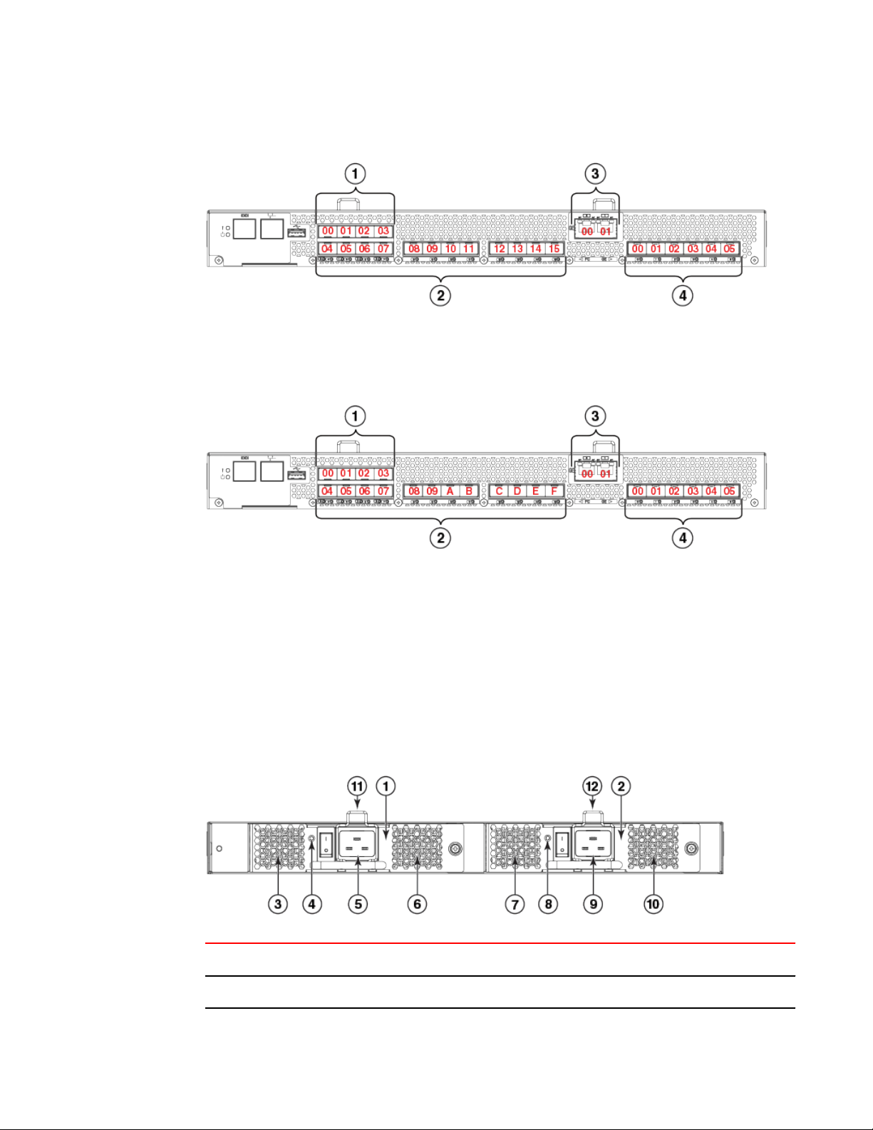
FIGURE 3 Trunking port groups and decimal PIDs of the Brocade 7800 Extension Switch
1. Trunking port group 1: FC ports 00-07
2. Trunking port group 2: FC ports 08-15
FIGURE 4 Trunking port groups and hexadecimal PIDs of the Brocade 7800 Extension Switch
1. Trunking port group 1: FC ports 00-07
2. Trunking port group 2: FC ports 08-0F
Nonport side of the Brocade 7800
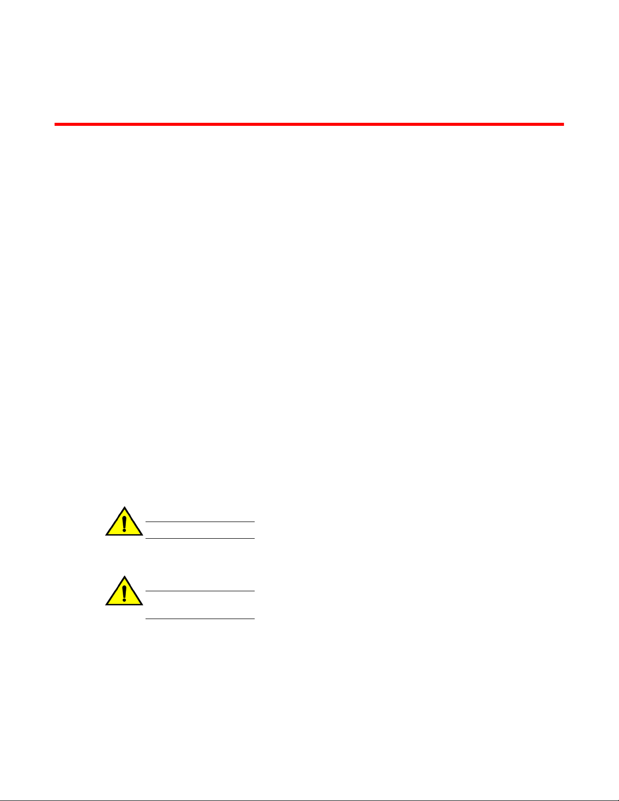
The following figure shows the nonport side of the Brocade 7800 Extension Switch, which contain the
combined power supplies and fans.
FIGURE 5 Nonport side of the Brocade 7800 Extension Switch
1 Fan and Power Supply Assembly 2
7 Fan assembly 1
2 Fan and Power Supply Assembly 1 8 FRU LED
Nonport side of the Brocade 7800
Brocade 7800 Extension Switch Hardware Reference Manual 17
53-1001350-05

3 Fan assembly 2 9 Power supply 1
4 FRU LED 10 Fan assembly 1
5 Power supply 2 11 FRU handle
6 Fan assembly 2 12 FRU handle
Brocade 7800 management
You can use the management functions built into the Brocade 7800 to monitor the fabric topology, port
status, physical status, and other information to help you analyze switch performance and to
accelerate system debugging.
NOTE
The Brocade 7800 automatically perform a power-on self-test (POST) each time it is turned on. Any
errors are recorded in the error log. For more information about POST, see POST and boot
specifications on page 51.
For information about upgrading the version of Fabric OS installed on your Brocade 7800, see the
Fabric OS Administrator's Guide
You can manage the Brocade 7800 using any of the management options listed in the following table.
Management options for the Brocade 7800TABLE 2
Management Tool Out-of-band Support In-band Support
Command line interface (CLI)
Up to two admin sessions and four user sessions
simultaneously. For more information, see the Fabric
OS Administrator's Guide and theFabric OS
Command Reference.
Ethernet (preferred) or
console port connection
IP over Fibre Channel
Brocade Data Center Fabric Manager (DCFM)
For information, see the Data Center Fabric Manager
User Manual .
Ethernet (preferred) or
console port connection
IP over Fibre Channel
Brocade Web Tools
For information, see the Web Tools Administrator's
Guide.
Ethernet (preferred) or
console port connection
IP over Fibre Channel
Standard SNMP applications
For information, see the Fabric OS MIB Reference.
Ethernet (preferred) or
console port connection
IP over Fibre Channel
Management Server
For information, see the Fabric OS Administrator's
Guide and theFabric OS Command Reference
Ethernet (preferred) or
console port connection
Native in-band
interface(over HBA only)
Brocade 7800 management
18 Brocade 7800 Extension Switch Hardware Reference Manual
53-1001350-05
Installing and configuring the Brocade 7800
● Installation and safety considerations............................................................................. 19
● Installation Precautions................................................................................................... 20
● Items included with the Brocade 7800 Extension Switch................................................21
● Setting up the Brocade 7800 Extension Switch as a standalone unit............................. 22
● Installing in an EIA rack...................................................................................................22
● Initial setup of the Brocade 7800.....................................................................................22
● Recommendations for cable management..................................................................... 31
Installation and safety considerations
You can install the Brocade 7800 in the following ways:
• As a standalone unit on a flat surface.
• In an EIA rack using the fixed rack mount kit, slide rack mount kit, or the mid-mount rack kit.
To install and operate the Brocade 7800 successfully, ensure that the following requirements are met:
• The primary AC input is 100-240 VAC (Brocade 7800 autosenses input voltage), 47-63 Hz.200-240
VAC is recommended.
• The primary outlet is correctly wired, protected by a circuit breaker, and grounded in accordance with
local electrical codes.
• The supply circuit, line fusing, and wire size are adequate, as specified by the electrical rating on the
Brocade 7800 nameplate.
For power supply information, see Power supply specifications on page 46 .
To ensure adequate cooling, install the Brocade 7800 with the nonport side, which contains the air
intake vents, facing a cool-air aisle.
CAUTION
Make sure the airflow around the front, sides, and back of the device is not restricted.
Verify that the ambient air temperature does not exceed 400° C (104° F) and that the ambient humidity
remains between 20% and 85% while the Brocade 7800 is operating.
CAUTION
Do not install the device in an environment where the operating ambient temperature might
exceed 40°C (104°F).
If installing the Brocade 7800 in a rack.
• The rack must be a standard EIA rack.
• Plan a rack space that is 1U (1.75 in.; 4.44 cm), 19 in. (48.3 cm) wide, and at least 24 in. (61cm)
deep.
• Ground all equipment in the rack through a reliable branch circuit connection and maintain ground at
all times. Do not rely on a secondary connection to a branch circuit, such as a power strip.
• Ensure that airflow and temperature requirements are met on an ongoing basis.
Brocade 7800 Extension Switch Hardware Reference Manual
19
53-1001350-05
• Verify that the additional weight of the Brocade 7800 does not exceed the rack’s weight limits or
unbalance the rack in any way.
• Secure the rack to ensure stability in case of unexpected movement.
DANGER
Make sure the rack housing the device is adequately secured to prevent it from becoming
unstable or falling over.
Installation Precautions
Review all installation precautions before installing the device. Refer to Cautions and Danger Notices
on page 59 for translations of all safety notices referenced in this manual.
General precautions
DANGER
The procedures in this manual are for qualified service personnel.
CAUTION
Changes or modifications made to this device that are not expressly approved by the party
responsible for compliance could void the user's authority to operate the equipment.
DANGER
All fiber-optic interfaces use Class 1 lasers.
Power precautions
This Extension Switch might have more than one power cord. To reduce the risk of electric shock,
disconnect both power cords before servicing.
DANGER
Remove both power cords before servicing.
DANGER
Disconnect the power cord from all power sources to completely remove power from the
device.
CAUTION
Before plugging a cable into to any port, be sure to discharge the voltage stored on the cable
by touching the electrical contacts to ground surface.
Connect the power cord only to a grounded outlet.
Installation Precautions
20 Brocade 7800 Extension Switch Hardware Reference Manual
53-1001350-05
Loading...