


 Loading...
53-1003081-01
8 January 2014
Brocade ICX 6450-C
Compact Switch
Hardware Installation Guide
Supporting FastIron Software Release 08.0.10
© 2014, Brocade Communications Systems, Inc. All Rights Reserved.
Brocade, the B-wing symbol, Brocade Assurance, ADX, AnyIO, DCX, Fabric OS, FastIron, HyperEdge, ICX, MLX, MyBrocade, NetIron, OpenScript, VCS, VDX, and Vyatta are registered trademarks, and The Effortless Network and the On-Demand Data Center are trademarks of Brocade Communications Systems, Inc., in the United States and in other countries. Other brands and product names mentioned may be trademarks of others.
Notice: This document is for informational purposes only and does not set forth any warranty, expressed or implied, concerning any equipment, equipment feature, or service offered or to be offered by Brocade. Brocade reserves the right to make changes to this document at any time, without notice, and assumes no responsibility for its use. This informational document describes features that may not be currently available. Contact a Brocade sales office for information on feature and product availability. Export of technical data contained in this document may require an export license from the United States government.
The authors and Brocade Communications Systems, Inc. assume no liability or responsibility to any person or entity with respect to the accuracy of this document or any loss, cost, liability, or damages arising from the information contained herein or the computer programs that accompany it.
The product described by this document may contain open source software covered by the GNU General Public License or other open source license agreements. To find out which open source software is included in Brocade products, view the licensing terms applicable to the open source software, and obtain a copy of the programming source code, please visit http://www.brocade.com/support/oscd.

Contents
Preface..................................................................................................................................... |
3 |
Document conventions...................................................................................... |
3 |
Brocade Resources........................................................................................... |
5 |
Getting technical help........................................................................................ |
5 |
Document feedback.......................................................................................... |
6 |
About This Guide....................................................................................................................... |
7 |
Introduction....................................................................................................... |
7 |
Supported Software.............................................................................. |
7 |
Product Overview....................................................................................................................... |
9 |
Hardware features............................................................................................. |
9 |
ICX 6450-C models............................................................................... |
9 |
Network and management interfaces............................................................... |
9 |
Console management interface ......................................................... |
10 |
Out-of-band management interface.................................................... |
10 |
Reset button........................................................................................ |
10 |
Network interfaces for an ICX 6450-C device..................................... |
10 |
Port, system, and power status LEDs............................................................. |
12 |
Port status LEDs................................................................................. |
12 |
System status LEDs............................................................................ |
13 |
Network connection status LEDs........................................................ |
14 |
Power supplies................................................................................................ |
16 |
AC power mode.................................................................................. |
16 |
PD power mode.................................................................................. |
17 |
ICX 6450-C Installation........................................................................................................... |
19 |
Items included with an ICX 6450-C device..................................................... |
19 |
Summary of installation tasks......................................................................... |
19 |
Installation precautions................................................................................... |
20 |
General precautions............................................................................ |
20 |
Lifting precautions............................................................................... |
20 |
Power precautions.............................................................................. |
21 |
Preparing the installation site.......................................................................... |
21 |
Cabling infrastructure.......................................................................... |
21 |
Installation location.............................................................................. |
22 |
Rack-mount installation considerations............................................... |
22 |
Installing the device......................................................................................... |
22 |
Desktop installation............................................................................. |
23 |
Rack mount installation....................................................................... |
23 |
Wall mount installation........................................................................ |
25 |
Wall mount installation using wall mount brackets.............................. |
28 |
Mounting the device with a magnet..................................................... |
30 |
Powering on the system.................................................................................. |
36 |
Configuring an ICX 6450-C device........................................................................................... |
37 |
Brocade ICX 6450-C Compact Switch Hardware Installation Guide |
1 |
53-1003081-01 |
|
IP address configuration............................................................................... |
37 |
Managing an ICX 6450-C device........................................................................................... |
39 |
Temperature settings.................................................................................... |
39 |
Displaying the temperature............................................................... |
39 |
Changing the temperature warning level ......................................... |
40 |
Temperature shutdown levels........................................................... |
40 |
Hardware Specifications....................................................................................................... |
41 |
AC power supply specifications.................................................................... |
41 |
Physical dimensions and weight................................................................... |
42 |
Environmental considerations....................................................................... |
42 |
Operating environment...................................................................... |
42 |
Pinouts and signalling................................................................................... |
43 |
Cable specifications.......................................................................... |
43 |
Power cords...................................................................................... |
44 |
Troubleshooting ................................................................................................................... |
45 |
Diagnosing switch indicators......................................................................... |
45 |
Power and cooling problems............................................................. |
45 |
Installation......................................................................................... |
45 |
Regulatory Statements.......................................................................................................... |
47 |
USA (FCC CFR 47 Part 15 Warning)............................................................ |
47 |
Industry Canada statement........................................................................... |
47 |
Europe and Australia (CISPR 22 Class A Warning)..................................... |
48 |
Germany (Noise Warning)............................................................................ |
48 |
Japan (VCCI)................................................................................................ |
48 |
Japan power cord.......................................................................................... |
48 |
Korea............................................................................................................. |
49 |
China............................................................................................................. |
50 |
BSMI statement (Taiwan).............................................................................. |
50 |
Regulatory compliance.................................................................................. |
51 |
Cautions and Danger Notices................................................................................................ |
53 |
Cautions........................................................................................................ |
53 |
Danger notices.............................................................................................. |
57 |
Index.................................................................................................................................... |
61 |
2 |
Brocade ICX 6450-C Compact Switch Hardware Installation Guide |
|
53-1003081-01 |

Preface
● Document conventions...................................................................................................... |
3 |
● Brocade Resources........................................................................................................... |
5 |
● Getting technical help........................................................................................................ |
5 |
● Document feedback.......................................................................................................... |
6 |
Document conventions
Describes text formatting conventions and important notice formats used in this document.
Text formatting conventions
The following text formatting conventions may be used in the flow of the text to highlight specific words or phrases.
Format
bold text
italic text
code
Description
Identifies command names
Identifies keywords and operands
Identifies the names of user-manipulated GUI elements Identifies text to enter at the GUI
Identifies emphasis
Identifies variables and modifiers
Identifies paths and Internet addresses
Identifies document titles
Identifies CLI output
Identifies command syntax examples
Command syntax conventions
The following text formatting conventions identify command syntax components.
Convention |
Description |
|
|
bold text |
Identifies command names, keywords, and command options. |
|
|
italic text |
Identifies a variable. |
|
|
value |
In Fibre Channel products, a fixed value provided as input to a command |
|
option is printed in plain text, for example, --show WWN |
|
|
Brocade ICX 6450-C Compact Switch Hardware Installation Guide |
3 |
53-1003081-01 |
|

Preface
Convention |
Description |
|
|
[ ] |
Syntax components displayed within square brackets are optional. |
|
Default responses to system prompts are enclosed in square brackets. |
|
|
{x|y|z} |
A choice of required parameters is enclosed in curly brackets separated by |
|
vertical bars. You must select one. |
|
In Fibre Channel products, square brackets may be used instead for this |
|
purpose. |
|
|
x|y |
A vertical bar separates mutually exclusive elements. |
< >
...
\
Nonprinting characters, for example, passwords, are enclosed in angle brackets.
Repeat the previous element. For example, member[member...]
Indicates a “soft” line break in command examples. If a backslash separates two lines of a command input enter the entire command at the prompt without the backslash
italic text |
Identifies a variable. |
|
|
bold text |
Identifies command names, keywords, and command options. |
|
|
Notes, cautions, and warnings
The following notices and statements may be used in this document. They are listed below in order of increasing severity of potential hazards.
NOTE
A note provides a tip, guidance, or advice, emphasizes important information, or provides a reference to related information.
ATTENTION
An Attention statement indicates potential damage to hardware or data.
CAUTION
A Caution statement alerts you to situations that can be potentially hazardous to you or cause damage to hardware, firmware, software, or data.
DANGER
A Danger statement indicates conditions or situations that can be potentially lethal or extremely hazardous to you. Safety labels are also attached directly to products to warn of these conditions or situations
4 |
Brocade ICX 6450-C Compact Switch Hardware Installation Guide |
|
53-1003081-01 |

Brocade Resources
Brocade Resources
Go to the Brocade website to locate related documentation for your product and additional Brocade resources.
Related publications
You can download additional publications supporting your product from the Brocade website at
www.brocade.com.
•Adapter documentation is available on the Downloads and Documentation for Brocade Adapters page. Select your platform and scroll down to the documentation section.
•For all other products, select the Brocade product to open the individual product page, click the Brocade product name or image to open the individual product page. The user manuals are available in the resources module at the bottom of the page under the Documentation category.
Additional Brocade resources
To get up-to-the-minute information, go to MyBrocade. You can register at no cost to obtain a user ID and password.
Release Notes are available on MyBrocade under Product Downloads.
White papers, online demonstrations, and data sheets are available through the Brocade website.
Getting technical help
Provides contact information for Brocade Technical Support.
For product support information and the latest information on contacting the Technical Assistance Center, go to http://www.brocade.com/services-support/index.html
Contact Brocade Support 24x7
Use one of the following methods to contact the Brocade Technical Assistance Center.
Online |
Telephone |
|
|
|
|
Preferred method of contact for non- |
Required for Sev 1-Critical and Sev |
||
urgent issues: |
2-High issues: |
||
• |
My Cases through MyBrocade |
• |
Continental US: |
• |
Software downloads & licensing |
|
1-800-752-8061 |
|
tools |
• |
Europe, Middle East, Africa, |
• |
Knowledge Base |
|
and Asia Pacific: +800-AT |
|
|
|
FIBREE (+800 28 34 27 33) |
|
|
• |
For areas unable to access toll |
|
|
|
free number: +1-408-333-6061 |
|
|
• |
Toll-free numbers are available |
|
|
|
in many countries. |
support@brocade.com
Please include:
•Problem summary
•Serial number
•Installation details
•Environment description
Brocade ICX 6450-C Compact Switch Hardware Installation Guide |
5 |
53-1003081-01 |
|
Document feedback
Document feedback
To send feedback and report errors in the documentation you can use the feedback form posted with the document, or you can email the documentation team.
Quality is our first concern at Brocade and we have made every effort to ensure the accuracy and completeness of this document. However, if you find an error or an omission, or you think that a topic needs further development, we want to hear from you. You can provide feedback in two ways:
•Through the online feedback form in the HTML documents posted on www.brocade.com.
•By sending your feedback to documentation@brocade.com.
Provide the publication title, part number, and as much detail as possible, including the topic heading and page number if applicable, as well as your suggestions for improvement.
6 |
Brocade ICX 6450-C Compact Switch Hardware Installation Guide |
|
53-1003081-01 |

About This Guide
● Introduction....................................................................................................................... |
7 |
Introduction
This guide includes procedures for installing and maintaining the hardware. The hardware procedures show how to install or assemble the various hardware components with the necessary precautions, warnings, and regulatory statements. This guide also describes the required device specifications for running the hardware.
Supported Software
For information about the features supported on a hardware platform, refer to the appropriate configuration guide.
Brocade ICX 6450-C Compact Switch Hardware Installation Guide |
7 |
53-1003081-01 |
|
Supported Software
8 |
Brocade ICX 6450-C Compact Switch Hardware Installation Guide |
|
53-1003081-01 |

Product Overview
● Hardware features............................................................................................................. |
9 |
● Network and management interfaces............................................................................... |
9 |
● Port, system, and power status LEDs............................................................................. |
12 |
● Power supplies................................................................................................................ |
16 |
Hardware features
The following sections describe the physical characteristics of an ICX 6450-C device. For more details about physical dimensions and power supply specifications, refer to the Hardware Specifications on page 41 chapter.
ICX 6450-C models
There is one ICX 6450-C model:
•ICX 6450-C12-PD: A compact switch with 12 10/100/1000 BASE-T ports (ports 1-4 are also PoEand MACsec-capable). This switch also has 2 x 10/100/1000 BASE-T RJ45 Uplink ports that are also Powered Device (PD) capable and 2 x 100M/1G SFP uplink ports. The uplink ports are also MACsec-capable.
FIGURE 1 ICX 6450-C12-PD front panel
FIGURE 2 ICX 6450-C12-PD rear panel
Network and management interfaces
The ICX 6450-C12-PD device includes the following management interfaces, and a reset button on the front panel of the device:
Brocade ICX 6450-C Compact Switch Hardware Installation Guide |
9 |
53-1003081-01 |
|
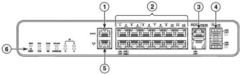
Console management interface
•Console management interface (RJ45 serial port)
•Out-of-band management interface (RJ45 port)
•Reset button
These RJ45 management ports are located together on the left side of the front panel as shown in the figure below.
1 |
Console port |
4 |
Slot 3 (SFP uplink ports) |
|
2 |
Slot 1 |
(10/100/1000 Mbps ports) |
5 |
Out-of-band management port |
3 |
Slot 2 |
(Copper uplink and PD ports) |
6 |
Reset button |
FIGURE 3 Management interfaces on an ICX 6450-C12-PD device
Console management interface
The console management interface is an RJ45 serial port that allows you to configure and manage the device using a third-party terminal emulation application from a directly connected PC.
Out-of-band management interface
The out-of-band management interface is an RJ45 port that allows you to configure and manage the device from the network.
Reset button
The reset button allows you to restart the system without switching the power supplies off and on or using the CLI. When the reset button is pressed, the system resets and the software is reloaded. The button is directly below the power LED on the very left of the device’s front panel.
Network interfaces for an ICX 6450-C device
An ICX 6450-C device contains the following interfaces:
•12 10/100/1000 BASE-T RJ45 copper connectors (Slot 1, Ports 1- 12)
Ports 1- 4 are dedicated PoE/PoE+ ports.
Ports 1- 4 are MACSec-ready.
•4 100M/1G ports:
2 10/100/1000 BASE-T, RJ45 ports (Slot 2, ports PD1/C1-PD2/C2); can be used as uplink or PD ports
2 100M/1G SFP uplink ports (Slot 3, ports F1-F2)
10 |
Brocade ICX 6450-C Compact Switch Hardware Installation Guide |
|
53-1003081-01 |

Slot designations
Slot designations
The table below lists the slot designations for an ICX 6450-C device. Refer to Figure 3 on page 10 for the location of slots 1- 3 on the front panel of an ICX 6450-C device.
TABLE 1 Slot designations for a ICX 6450-C device
Device |
Slot 1 (10/100/1000 BASE-T |
Slot 2 (10/100/1000 BASE-T |
Slot 3 (1G SFP uplink |
|
RJ45 ports) |
RJ45 uplink ports) |
ports) |
|
|
|
|
ICX 6450-C12-PD |
Ports 1-12 |
Ports PD1/C1-PD2/ C2 |
Ports F1-F2 |
|
|
|
|
10/100/1000 BASE-T RJ45
An ICX 6450-C device provides 12 RJ45 ports that reside on Slot 1 of the device. The 12 RJ45 ports operate at 10 Mbps or 100 Mbps half or full duplex, or at 1000 Mbps full duplex. Because all ports support automatic MDI or MDI-X operation, you can use straight-through cables for all network connections to PCs or servers, or to other devices or hubs. In addition, it is ideal (and preferred) to use straight-through cables for switch-to-switch connections.
Each port supports auto-negotiation, so the optimum transmission mode (half or full duplex), and the data rate (10, 100, or 1000 Mbps) can be selected automatically. If a device connected to one of these ports does not support auto-negotiation, the communication mode of the port can be configured manually.
Ports 1-4 are PoE+ and MACsec-capable. Ports 5-12 are non-PoE.
SFP and RJ45 uplink ports
An ICX 6450-C device provides 4 independent uplink ports that are MACsec-capable.
The 10/100/1000 BASE-T RJ45 PD1/C1 and PD2/C2 ports, residing on slot 2 of the device, can be used as uplink ports or additional network connections. They can also be used as PD ports.
The other 2 uplink ports are 100M/1G small form factor pluggable (SFP) ports (ports F1 and F2), which reside on slot 3 of the switch. The SFP ports support 100Mbps/1GbE port speeds.
For information about supported SFP transceivers, refer to the following Brocade website:
http://www.brocade.com/downloads/documents/data_sheets/product_data_sheets/Optics_DS.pdf
MACsec-Capable Ports
The ICX 6450-C device provides 8 ports that are MACsec-capable, as shown in the figure below.
FIGURE 4 MACsec-capable ports on an ICX 6450-C12-PD device
Brocade ICX 6450-C Compact Switch Hardware Installation Guide |
11 |
53-1003081-01 |
|

Port, system, and power status LEDs
Port, system, and power status LEDs
An ICX 6450-C device include LEDs that indicate the status of device components:
•Port status LEDs on page 12
•System status LEDs on page 13 (including power status LEDs)
•Network connection status LEDs on page 14
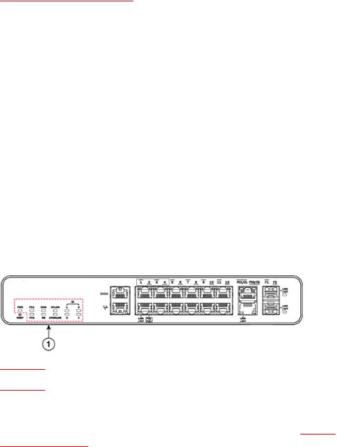
Port status LEDs
The figure shows the location of the port status LEDs on the ICX 6450-C12-PD model.
1 Port status LEDs
2PoE/PoE+ LEDs
FIGURE 5 Port status LEDs an ICX 6450-C12-PD device
The table below lists the port status LEDs on an ICX 6450-C device and their corresponding conditions and status.
TABLE 2 Port status LEDs
LED |
Condition |
Status |
|
|
|
|
|
Out-of-band management port (2 |
Off (right side) |
Offline |
|
LEDs) |
|
|
|
On/Flashing (left side) |
Link-up. Flashing indicates the port is |
||
|
|||
|
|
transmitting and receiving user packets. |
|
|
|
|
|
|
On/Green (right side) |
1 Gbps Link-up |
Right LED off, left LED on or flashing
10/100 Mbps Link-up. Flashing indicates the port is transmitting and receiving user packets.
1GbE ports |
Off (right side) |
The right LED on the ports indicates PoE/PoE+ |
|
(1 - 12, Slot 1) |
|
activity and is only active on ports 1-4. On non- |
|
|
PoE/PoE+ ports, the right LED remains off. |
||
|
|
||
Link/Act |
|
|
|
Off (left side) |
A link is not established with a remote port. |
||
|
|||
|
|
|
|
|
On/Flashing Green |
The port has established a valid link at 10, 100 |
|
|
(left side) |
or 1000 Mbps. Flashing indicates the port is |
|
|
|
transmitting and receiving user packets. |
|
|
|
|
12 |
Brocade ICX 6450-C Compact Switch Hardware Installation Guide |
|
53-1003081-01 |
System status LEDs
TABLE 2 Port status LEDs (Continued)
LED |
Condition |
Status |
|
|
|
PoE/PoE+(1 - 4) |
On/Green (right side) |
The port is providing PoE or PoE+ power to a |
|
|
connected device. |
|
|
|
|
Off (right side) |
The port is not providing PoE or PoE+ power. |
|
|
|
100M/1GbE RJ45 ports(PD1/C1 - |
On/ Flashing Green |
The port is operating at 1 Gbps. Flashing |
PD2/C2, Slot 2) |
|
indicates the port is transmitting and receiving |
Link/Act |
|
user packets at 1 Gbps. |
|
|
|
|
Off |
A link is not established with a remote port. |
|
|
|
100M/1GbE SFP ports(F1 - F2, Slot 3) |
On/ Flashing Green |
The SFP port is operating at 1 Gbps. Flashing |
Link/Act |
|
indicates the port is transmitting and receiving |
|
user packets at 1 Gbps. |
|
|
|
|
|
|
|
|
Off |
A link is not established with a remote port. |
|
|
|
System status LEDs
The figure below shows the location of the system status LEDs on an ICX 6450-C device.
FIGURE 6 System status LEDs on an ICX 6450-C12-PD device
1System status LEDs
The table below lists the system status LEDs on an ICX 6450-C device and their corresponding conditions and status.
TABLE 3 System status LEDs
LED |
Condition |
Status |
|
|
|
PWR |
Green |
Power source is the AC power supply and is |
(Power) |
|
operating normally. |
|
|
|
|
Amber |
Power source is the PD ports and is |
|
|
operating normally. |
|
|
|
|
Off |
Power supply off. |
|
|
|
PD1 and PD2 |
Green |
PD port source is PoE+. |
|
|
|
Brocade ICX 6450-C Compact Switch Hardware Installation Guide |
13 |
53-1003081-01 |
|

Network connection status LEDs
TABLE 3 System status LEDs (Continued)
LED |
Condition |
Status |
|
|
|
|
Amber |
PD port source is PoE. |
|
|
|
|
Off |
PD port source if off. |
Diag (Diagnostic)
Flashing Green System self-diagnostic test in progress. System reloads automatically.
Steady Amber System self-diagnostic test has detected a fault. (Fan, thermal, or any interface fault.)
The user must reload the system.
|
Steady Green |
System self-diagnostic test passed. |
|
|
|
|
|
|
|
||
Uplink |
LED is reserved for future use. |
|
Downlink LED is |
||
|
|
|
|
|
reserved for |
|
|
|
|
|
|
ID (1-4) |
Off |
LED is reserved for future use. |
|
|
future use. |
(Reserved for future use)
Network connection status LEDs
After you install the network cables, you can observe certain LEDs to determine if the network connections are functioning properly. The table below outlines the LEDs related to the network connections, the desired state of each LED, possible abnormal states of each LED, and what to do if an LED indicates an abnormal state.
TABLE 4 Network connection-related LED states
LED |
Desired |
Meaning |
Abnormal Meaning or action |
|
state |
|
state |
Ethernet |
On or |
The port has |
Off |
(1-12, Slot |
flashing |
established a valid |
|
1) |
(Green) |
link at 10, 100 or |
|
Link/Act |
|
1000 Mbps. Flashing |
|
|
indicates the port is |
|
|
|
|
|
|
|
|
transmitting and |
|
|
|
receiving user |
|
|
|
packets. |
|
A link is not established with the remote port. You can do the following:
•Verify that the connection to the other network device has been properly made. Also, make certain that the other network device is powered on and operating correctly.
•Verify that the port has not been disabled through a configuration change. You can use the CLI. If you have configured an IP address on the device, you also can use the Web management interface or Brocade Network Advisor.
•If the other actions do not resolve the problem, try using a different port or a different cable.
14 |
Brocade ICX 6450-C Compact Switch Hardware Installation Guide |
|
53-1003081-01 |

Product Overview
TABLE 4 Network connection-related LED states (Continued)
LED |
Desired |
Meaning |
Abnormal Meaning or action |
|
state |
|
state |
PoE/PoE+ On
(1-4, Slot 1) (Green)
Ports 1-4 have two |
Off |
LEDs. The one on |
|
the left indicates |
|
Link/Act activity as |
|
described above. |
|
The LED on the right, if on (steady green), indicates that this device is acting as Power Sourcing
Equipment (PSE) and is providing PoE/PoE+ power to down stream devices.
A link is not established with the PoE device. You can do the following:
•Verify that the connection to the other network device has been properly made.
•If the other actions do not resolve the problem, try using a different port or a different cable.
SFP(F1 - |
On or |
The SFP port is |
Off |
A link is not established with the remote port. You |
|
F2, Slot 3) |
flashing |
operating. Flashing |
|
can do the following: |
|
|
(Green) |
green indicates the |
|
• |
Verify that the connection to the other |
|
|
port is transmitting |
|
||
|
|
|
|
network device has been properly made. |
|
|
|
and receiving user |
|
|
|
|
|
|
|
Also, make certain that the other network |
|
|
|
packets. |
|
|
|
|
|
|
|
device is powered on and operating correctly. |
|
|
|
|
|
|
|
|
|
|
|
• |
Verify that the transmit port on the device is |
|
|
|
|
|
connected to the receive port on the other |
|
|
|
|
|
network device, and that the receive port on |
|
|
|
|
|
the device is connected to the transmit port |
|
|
|
|
|
on the other network device. If you are not |
|
|
|
|
|
certain, remove the two cable connectors |
|
|
|
|
|
from the port connector and reinsert them in |
|
|
|
|
|
the port connector, reversing their order. |
|
|
|
|
• |
Dust may have accumulated in the cable |
|
|
|
|
|
connector or port connector. |
|
|
|
|
• |
Verify that the port has not been disabled |
|
|
|
|
|
through a configuration change. |
|
|
|
|
• |
If the other actions do not resolve the |
|
|
|
|
|
problem, try using a different port or a |
|
|
|
|
|
different cable. |
|
|
|
|
|
|
Uplink |
On or |
The ports are |
Off |
A link is not established with the remote port. You |
|
ports |
flashing |
operating. Flashing |
|
can do the following: |
|
(PD1/C1- |
(Green) |
green indicates the |
|
• |
Verify that the connection to the other |
|
port is transmitting |
|
|||
PD2/C2, |
|
|
|
network device has been properly made. |
|
|
and receiving user |
|
|
||
Slot 2) |
|
|
|
Also, make certain that the other network |
|
|
packets. |
|
|
||
|
|
|
|
device is powered on and operating correctly. |
|
|
|
|
|
|
|
|
|
|
|
• |
Verify that the port has not been disabled |
|
|
|
|
|
through a configuration change. You can use |
|
|
|
|
|
the CLI. If you have configured an IP address |
|
|
|
|
|
on the device, you also can use the Web |
|
|
|
|
|
management interface or Brocade Network |
|
|
|
|
|
Advisor. |
|
|
|
|
• |
If the other actions do not resolve the |
|
|
|
|
|
problem, try using a different port or a |
|
|
|
|
|
different cable. |
|
|
|
|
|
|
If a problem persists after taking these actions, contact Brocade Technical Support.
Brocade ICX 6450-C Compact Switch Hardware Installation Guide |
15 |
53-1003081-01 |
|

Power supplies
Power supplies
An ICX 6450-C device has one standard power supply receptacle on the rear panel of the device for the AC power cord.
FIGURE 7 ICX 6450-C AC power connection
1Kensington lock hole
2AC power supply socket
AC power mode
The table below shows the device power usage and the PoE/PoE+ power configurations available to PSE ports in the AC power mode.
When you use the AC power supply, PD is disabled. The only power to the system comes from the AC power supply. In this mode, the ICX 6450-C device can provide PSE power through ports 1-4 to downstream devices. The total power available to the PSE ports (ports 1-4) is 68W.
TABLE 5 Device power usage and available PoE/PoE+ power configurations in the AC power mode
Power |
Uplink (PD |
Minimum |
Effective |
System |
Does ICX |
Power available to PSE |
|
Input |
ports) power |
input power |
power (W) |
power (W) |
6450-C12- |
ports (W) |
|
|
inputs |
PD |
|
|
|||
|
|
(W) |
|
|
turn on? |
|
|
|
|
|
|
|
|
|
|
|
|
|
|
|
|
|
|
AC input |
All PD inputs |
Two uplink |
100 |
20.07 |
Yes |
68 in one of these |
|
only or AC |
are disabled if |
802.3af PD |
|
|
|
configurations: |
|
input with |
AC power is |
ports or one |
|
|
|
• |
Four Class 3 devices |
uplink PD |
present. |
uplink 802.3at |
|
|
|
||
|
|
|
• |
One Class 4 device, |
|||
inputs |
|
PD port |
|
|
|
||
|
|
|
|
|
|
|
two Class 3 devices, |
|
|
|
|
|
|
|
and one Class 2 |
|
|
|
|
|
|
|
device |
|
|
|
|
|
|
• |
One Class 3 device |
|
|
|
|
|
|
• |
Two Class 4 devices |
|
|
|
|
|
|
|
and one Class 2 |
|
|
|
|
|
|
|
device |
|
|
|
|
|
|
|
|
When using the ICX 6450-C device to provide PoE/PoE+ power to down-stream devices, keep in mind that the maximum allowed continuous power per cable depends on the standard being used, as shown in the table below:
16 |
Brocade ICX 6450-C Compact Switch Hardware Installation Guide |
|
53-1003081-01 |

PD power mode
TABLE 6 Maximum PSE output power
Standard |
Maximum power |
|
|
IEEE 802.3af (PoE) |
15.40W |
|
|
IEEE 802.3at (PoE+) |
30W |
|
|
PD power mode
In the PD power mode, the ICX 6450-C switch is powered by a PSE source through the PD ports (ports PD1 and PD2). Also in this mode, the switch can provide passthrough PoE power to down-stream devices through the PSE ports (ports 1-4).
The table below shows the ICX 6450-C switch power usage in the PD power mode. When powering the device using the PD ports, keep in mind that the maximum allowed continuous power per cable depends on the standard being used, as shown in AC power mode on page 16.
TABLE 7 Device power usage and available PoE/PoE+ power configurations in the PD power mode
AC Input |
Uplink (PD ports) |
Minimum |
System |
Is the PD power |
Power available to |
|
|
power inputs |
input power (W) |
power (W) |
enough to turn ICX |
PSE ports (W) |
|
|
|
|
6450-C12-PD on? |
|
||
|
|
|
|
|
|
|
None |
1 PoE |
12.95 |
N/A |
No |
N/A |
|
|
|
|
|
|
|
|
None |
2 |
PoE |
25.9 |
20.07 |
Yes |
N/A |
|
|
|
|
|
|
|
None |
1 |
PoE+ |
25.4 |
20.07 |
Yes |
N/A |
|
|
|
|
|
|
|
None |
1 PoE+ and 1 PoE |
38.35 |
20.07 |
Yes |
7 |
|
|
|
|
|
|
|
|
None |
2 |
PoE+ |
50.8 |
20.07 |
Yes |
22.4 |
|
|
|
|
|
|
|
NOTE
When the show chassis command displays the message "Power supply present status failed," it is an indication that there is no AC power supply and that the device is powered through PD ports, drawing PoE.
Brocade ICX 6450-C Compact Switch Hardware Installation Guide |
17 |
53-1003081-01 |
|
PD power mode
18 |
Brocade ICX 6450-C Compact Switch Hardware Installation Guide |
|
53-1003081-01 |
Loading...