

Bosch D8132LT Installation Manual
Battery Charger Modules
D8132 and D8132LT
en Installation Guide

!
Battery Charger Modules Notices | en 3
1
Notices
These instructions cover the installation of the D8132 Battery Charger and the D8132LT
Battery Charger Less Transformer modules in an alarm system supervised by a fire alarm
control panel (FACP), an intrusion alarm panel, or a combination Burglary/Fire control panel.
These modules are UL Listed for use in Central Station, Household Fire and Burglary Alarm,
Police Connection, and Electrically Actuated Transmitter applications. They can also be
installed as non-UL Listed , 12 V, 1 A, standalone power supplies.
To obtain any of the documents referenced in this document, download them from the Bosch
website (www.boschsecurity.com).
Install, test and maintain the module according to these instructions, NFPA codes, local codes,
and the authority having jurisdiction (AHJ). Failure to follow these instructions can result in
failure of a detector to initiate an alarm event. Bosch Security Systems, Inc. is not responsible
for improperly installed, tested or maintained devices.
Before installing the module, become familiar with the Installation and Operation Guide for the
control panel you are using.
Warning!
Follow these instructions to avoid personal injury and damage to equipment.
NFPA 72 requires that you perform a complete system wide functional test following any
modifications, repair, upgrades or adjustments made to the system’s components, hardware,
wiring, programming and software/firmware.
Copyright
This document is the intellectual property of Bosch Security Systems, Inc. and is protected by
copyright. All rights reserved.
Trademarks
All hardware and software product names used in this document are likely to be registered
trademarks and must be treated accordingly.
Bosch Security Systems, Inc. Installation Guide 2014.07 | 1.0 | F.01U.036.305
4 en | Description Battery Charger Modules
2
Description
The module, combined with external batteries, increases the standby time and provides
additional power to the auxiliary output of the compatible control panels listed in the
following table.
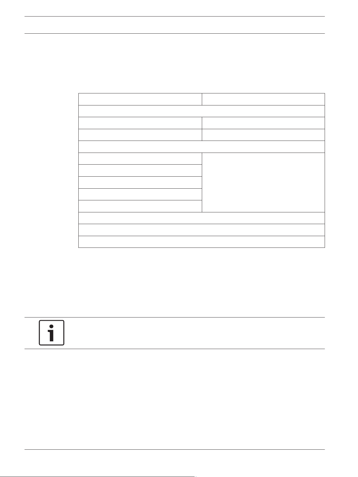
Control Panels See section:
Active products:
GV4 and GV3 panels
D6412 and D4412 panels
Legacy products:
GV2 and G panels
D9412, D7412, D7212, D7212B1
D9112B1, D9112, D8112, D6112
D9124
2000-series panels
1
GV4 = D9412GV4, D7412GV4, & D7212GV4; GV3 = D9412GV3, D7412GV3, & D7212GV3
2
GV2 = D9412GV2, D7412GV2, & D7212GV2; G = D9412G, D7412G, & D7212G
3
2000-series = D2812, D2412, D2212, D2212B, D2212BE, & D2012
1
2
See control panel’s documentation on the
Wiring, page 6
Bosch website (http://
www.boschsecurity.com)
3
In addition to the batteries that can be installed with the control panel, two additional 12 V,
7 Ah batteries (D126) or up to two 12 V, 13.5 Ah batteries can be installed with the module.
The module is ideal for systems requiring extended battery standby time, such as UL Bank
Safe and Vault applications, and systems requiring additional auxiliary current output. In
addition to providing increased standby time and auxiliary power, the batteries also filter the
AC power supply. The amount of ripple that appears on the control panel outputs is
dependent on the condition of the batteries.
Notice!
Bosch does not recommend using the module to power devices that are sensitive to
excessive ripple.
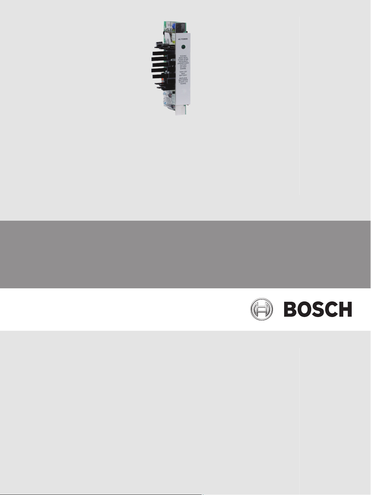
A 16.5 V, 40 VA transformer (D1640, supplied with the D8132) is required to power the
module. A green LED on the module lights to indicate the presence of AC power.
Provided with the D8132LT are two cables, and two sets of lockwashers, nuts, screws, and
terminal lugs. The cables connect the module to the transformer, two batteries, and the
control panel. The hardware is provided for connecting the battery cable to 12 V, and up to
two 13.5 Ah batteries (this hardware is not used when connecting 12 V, 7 Ah batteries).
2014.07 | 1.0 | F.01U.036.305 Installation Guide Bosch Security Systems, Inc.
 Loading...