

Bosch D7212GV4K7 Installation Manual
1 | Overview
The B208 Octo-input Module is an 8 point supervised expansion
device that connects to control panels through the SDI2 bus.
This module communicates back to the control panel all point
status changes. The inputs are accessed through on-board screw
terminal connections.
6
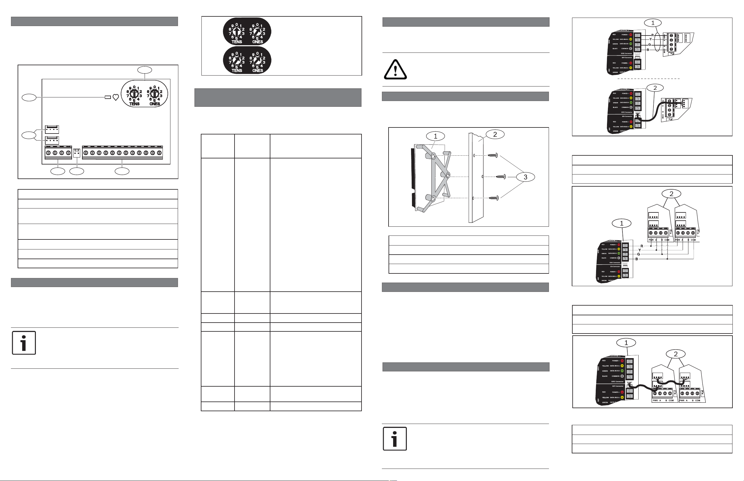
Figure 2.1: Address switches
= Inputs 11 to 18
= Inputs 111 to 118
3 | Installation
After you set the address switches for the proper address,
install the module in the enclosure, and then wire it to the
control panel.
CAUTION!
Remove all power (AC and battery) before making any
connections. Failure to do so might result in personal
injury and/or equipment damage.
1
2
TMPR
PWR A B COM
3 4 5
Figure 1.1: Board overview
1 COM 2
3 COM 4 5 COM 6
7 COM 8
Callout ― Description
1 ― Heartbeat LED (blue)
2 ― SDI2 interconnect wiring connectors
(to control panel or additional modules)
3 ― SDI2 terminal strip
(to control panel or additional modules)
4 ― Tamper switch connector
5 ― Terminal connector (point inputs)
6 ― Address switches
2 | SDI2 address settings
Two address switches determine the address for the B208
Octo-input Module. The control panel uses the address for
communications. The address also determines the output
numbers. Use a slotted screwdriver to set the two address
switches.
NOTICE!
The module reads the address switch setting only
during power up. If you change the switches after
you apply power to the module, you must cycle the
power to the module to enable the new setting.
Set the address switches per the control panel confi guration. If
multiple B208 modules reside on the same system, each B208
module must have a unique address.
The module’s address switches provide a tens and ones value
for the module’s address. For single-digit address numbers 1
through 9, set the tens switch to 0 and the ones digit to the
appropriate number. Figure 2.1 shows the address switches
setting for addresses 1 and 11.
2.1 | Valid addresses and input numbers per
control panel
Valid B208 addresses are dependent on the number of points
allowed by a particular control panel. Addresses higher than 32
require B208 fi rmware version 1.03.003 or higher.
Control
panel
B9512G 01 - 59 11 - 18, 21 - 28, 31 - 38, 41 - 48,
B8512G 01 - 09 11 - 18, 21 - 28, 31 - 38, 41 - 48,
B5512 01 - 04 11 - 18, 21 - 28, 31 - 38, 41 - 48
B4512 01 - 02 11 - 18, 21 - 28
D9412GV4 01 - 24 11 - 18, 21 - 28, 31 - 38, 41 - 48,
D7412GV4 01 - 07 11 - 18, 21 - 28, 31 - 38, 41 - 48,
D7212GV4 01 - 03 11 - 18, 21 - 28, 31 - 38
To determine the point numbers for each address, multiply
the address number by 10 for the base number, and then use
numbers 1 through 8 in the ones place for the point numbers.
For examples, refer to Section 8.
Valid
B208
addresses
Corresponding point
numbers
51 - 58, 61 - 68, 71 - 78,
81 - 88, 91 - 98, 101 - 108,
111 - 118, 121 - 128, 131 - 138,
141 - 148, 151 - 158, 161 - 168,
171 - 178, 181 - 188, 191 - 198,
201 - 208, 211 - 218, 221 - 228,
231 - 238, 241 - 248, 251 - 258,
261 - 268, 271 - 278, 281 - 288,
291 - 298, 301 - 308, 311 - 318,
321 - 328, 331 - 338, 341 - 348,
351 - 358, 361 - 368, 371 - 378,
381 - 388, 391 - 398, 401 - 408,
411 - 418, 421 - 428, 431 - 438,
441 - 448, 451 - 458, 461 - 468,
471 - 478, 481 - 488, 491 - 498,
501 - 508, 511 - 518, 521 - 528,
531 - 538, 541 - 548, 551 - 558,
561 - 568, 571 - 578, 581 - 588,
591 - 598
51 - 58, 61 - 68, 71 - 78, 81 - 88,
91 - 98
51 - 58, 61 - 68, 71 - 78,
81 - 88, 91 - 98, 101 - 108,
111 - 118, 121 - 127, 131 - 138,
141 - 148, 151 - 158, 161 - 168,
171 - 178, 181 - 188, 191 - 198,
201 - 208, 211 - 218, 221 - 228,
231 - 238, 241 - 247
51 - 58, 61 - 68, 71 - 75
3.1 | Mount the module in the enclosure
Mount the module into the enclosure’s 3-hole mounting
pattern using the supplied mounting screws and mounting
bracket. Refer to Figure 3.1.
Figure 3.1: Mounting the module in the enclosure
Callout ― Description
1 ― Module with mounting bracket installed
2 ― Enclosure
3 ― Mounting screws (3)
3.2 | Mount and wire the tamper switch
You can connect an optional enclosure door tamper switch
for one module in an enclosure.
Installing the optional tamper switch:
1. Mount the ICP-EZTS Tamper Switch (P/N: F01U009269)
into the enclosure’s tamper switch mounting location.
For complete instructions, refer to EZTS Cover and Wall
Tamper Switch Installation Guide (P/N: F01U003734).
2. Plug the tamper switch wire onto the module’s tamper
switch connector. Refer to Figure 1.1.
3.3 | Wire to the control panel
When you wire the module to a control panel, you can use either
the module’s terminal strip labeled with PWR, A, B, and COM,
or the module’s interconnect wiring connectors (wire included).
Interconnect wiring parallels the PWR, A, B, and COM terminals
on the terminal strip. Figure 1.1 indicates the location of both
the terminal strip and the interconnect connectors on the
module.
Refer to Figures 3.2, 3.3, and 3.4.
NOTICE!
Use either the terminal strip wiring or interconnect
wiring connector to the control panel. Do not use
both. When connecting multiple modules, you can
combine terminal strip and interconnect wiring
connectors in series.
Figure 3.2: Using terminal strip or interconnect cable wiring
D9412GV4 shown)
Callout ― Description
1 ― Terminal strip wiring (SDI2)
2 ― Interconnect cable (P/N: F01U079745) (included)
Figure 3.3: Installing multiple modules using the SDI2 terminal
strip (D9412GV4 shown)
Callout ― Description
1 ― Bosch control panel
2 ― B208 modules
Figure 3.4: Installing multiple modules using the SDI2
interconnect wiring connector (D9412GV4 shown)
Callout ― Description
1 ― Bosch control panel
2 ― B208 modules
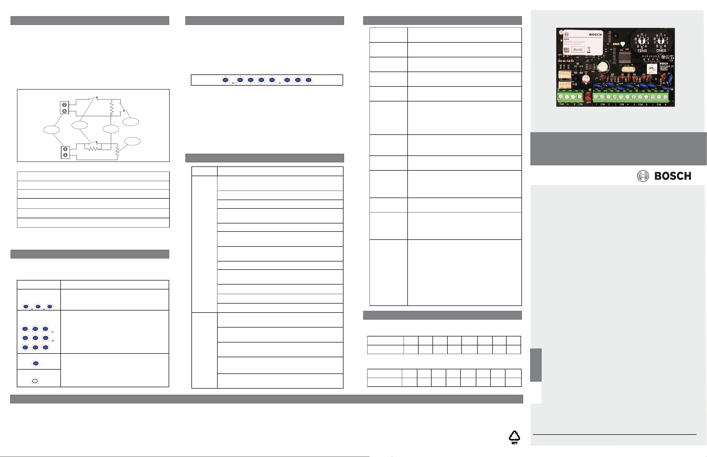
3.4 | Sensor loop wiring
Wire resistance on each sensor loop must be less than 100
Ω with the detection devices connected. The terminal strip
supports 12 to 22 AWG (0.65 to 2 mm) wires.
The B208 detects open, short, normal, and ground fault circuit
conditions on its sensor loops and transmits the conditions to
the control panel. Each sensor loop is assigned a point number
and transmits to the control panel individually.
from the premises telephone and AC wiring.
Run wires away
For the dual
EOL resistor circuit style order ICP-1K22AWG-10, a package of
10 1.0 kΩ EOL resistors.
NC
Point
COM
1
Point
COM
1.0 k:
2
NC
1.0 k:
1.0 k:
NO
5
3
4
Figure 3.5: Sensor loop wiring single (upper) and dual (lower)
Callout ― Description
1 ― Point sensor loop terminals
2 ― Normally closed device (contact)
3 ― 1 kΩ resistor at device
4 ― 1 kΩ resistor at end-of-line (EOL)
5 ― Normally open device (contact)
Dual EOL requires B208 fi rmware v1.05.001 or higher. Dual
EOL meets the requirement of double protection for medium to
high risk ULC installations.
4 | LED descriptions
The module includes one blue heartbeat LED to indicate
that the module has power and to indicate the module’s
current state. Refer to Table 4.1.
Flash Pattern Function
Flashes once
every 1 sec
3 quick fl ashes
every 1 sec
ON Steady LED trouble state: Module is not
OFF Steady
Table 4.1: LED descriptions
Normal state: Indicates normal operation
state.
Communication error state: Indicates
(the module is in a “no communication
state”) resulting in an SDI2
communication error.
powered (for OFF Steady only), or some
other trouble condition prohibits the
module from controlling the heartbeat
LED.
5 | Show the fi rmware version
To show the fi rmware version using an LED fl ash pattern:
- If the optional tamper switch is installed:
With the enclosure door open, activate the tamper switch
(push and release the switch).
- If the optional tamper switch is NOT installed:
Momentarily short the tamper pins.
Refer to Figure 5.1 for an example of fl ash pattern
s.
Figure 5.1: Firmware LED fl ash patterns
When the tamper switch is activated, the heartbeat LED
stays OFF for 3 seconds before indicating the fi rmware
version. The LED pulses the major, minor, and micro digits of
the fi rmware version, with a 1 second pause after each digit.
In the following example, the version 1.4.3 shows as LED
fl ashes:
[3 second pause] *___****___*** [3 second pause, then
normal operation].
6 | Certifi cations
Region
USA UL 365 - Police Station Connected Burglar Alarm
Units and Systems
UL 609 - Local Burglar Alarm Units and Systems
UL 636 - Holdup Alarm Units and Systems
UL 864 - Control Units and Accessories for Fire
Alarm Systems (Commercial Fire)
UL 985 - Household Fire Warning System Units
UL 1023 - Household Burglar Alarm System
Units
UL 1076 - Proprietary Burglar Alarm Units and
Systems
UL 1610 - Central Station Burglar Alarm Units
CSFM - California Offi ce of The State Fire Marshall
FCC Part 15 Class B
FDNY - Fire Department of New York
FM 3010 - Fire Alarm Signaling Systems
Canada CAN/ULC S303 - Local Burglar Alarm Units and
Systems
CAN/ULC S304 - Signal Receiving Centre and
Premise
ICES-003 - Information Technology Equipment
(ITE)
ULC-ORD C1023 - Household Burglar Alarm
System Units
ULC-ORD C1076 - Proprietary Burglar Alarm
Units and System
7 | Specifi cations
Dimensions 2.5 in x 3.8 in x 0.60 in
(63.75 mm x 96 mm x 15.25 mm)
Voltage
12 V nominal
(operating)
Current
35 mA
(maximum)
Operating
+32°F to +122°F (0°C to +50°C)
temperature
Relative
humidity
5% to 93% at +90°F (+32°C) noncondensing
Loop inputs Up to eight inputs. Input contacts may be
Normally Open (NO) or Normally Closed
(NC).
NOTICE! Normally Closed (NC) is not
permitted in Fire installations.
Loop End-ofLine (EOL)
resistance
Loop wiring
Loops can be confi gured for single or
dual EOL resistor circuit style using 1k Ω
resistors.
100 Ω maximum
resistance
Loop states
(Single EOL
resistor
Short: 0 - 1.1 VDC
Normal: 1.25 - 1.9 VDC
Open: 2.25 - 5 VDC
circuit style)
Terminal
12 AWG to 22 AWG (2 mm to 0.65 mm)
wire size
SDI2 wiring Maximum distance - Wire size (Unshielded
wire only):
1000 ft (305 m) - 22 AWG (0.65 mm)
1000 ft (305 m) - 18 AWG (1.02 mm)
Compatibility B9512G/B9512G-E
B8512G/B8512G-E
B5512/B5512E
B4512/B4512E
D9412GV4
D7412GV4
D7212GV4
(Refer to the control panel installation
document for number of supported
devices.)
8 | Point number examples
For B208 address 01 the point numbers for the input devices are
11 through 18:
Terminal no 12345 678
Input no 11 12 13 14 15 16 17 18
For B208 address 11 the point numbers for the input devices are
111 through 118:
Terminal no 12345 678
Input no 111 112 113 114 115 116 117 118
Octo-input Module
B208
en Installation Guide
Bosch Security Systems, Inc.
130 Perinton Parkway
Fairport, NY 14450
USA
www.boschsecurity.com
Bosch Sicherheitssysteme GmbH
Robert-Bosch-Ring 5
85630 Grasbrunn
Germany
Copyright
This document is the intellectual property of Bosch Security Systems, Inc. and is protected by copyright. All rights reserved.
Trademarks
All hardware and software product names used in this document are likely to be registered trademarks and must be treated accordingly.
Bosch Security Systems, Inc. product manufacturing dates
Use the serial number located on the product label and refer to the Bosch Security Systems, Inc. website at http://www.boschsecurity.com/datecodes/.
© 2015 Bosch Security Systems, Inc. F.01U.265.456 | 05 | 2015.06
 Loading...