

Ethernet Communication Module
B420
en Installation and Operation Guide


Ethernet Communication Module Table of Contents | en 3
Table of Contents
1 Introduction 4
1.1 Reading Bosch Security Systems, Inc. Product Date Codes 4
1.2 Trademarks 4
1.3 Overview B420 4
1.4 Technical Specifications 7
1.5 Certifications 7
2 Installation 8
3 Configuration 12
3.1 Configuring for SDI2 Control Panels (GV4 Only) 12
3.1.1 Address-only Configuration for SDI2 Control Panels 12
3.1.2 Web-based Configuration for SDI2 Control Panels 12
3.2 Configuring for SDI or Option Bus Control Panels 12
3.2.1 Address-only Configuration for SDI or Option Control Panels 12
3.2.2 Web-based Configuration for SDI2 or Option Bus Control Panels 13
3.3 Determining a Module’s Hostname or IP Address 13
3.3.1 Determining a Module’s Hostname 13
3.3.2 Using a GV4 Series Keypad to Discover the IP Address of a Module 13
3.3.3 Using DHCP to Look Up the IP Address of a Network-connected Module 13
3.3.4 Using Auto IP with a Directly Connected Module 14
3.4 Accessing the B420 Configuration Pages 14
3.5 Device Information (Home) Page 15
3.6 Changing and Saving Settings Using the Web 16
3.7 Basic Network Settings Page 16
3.8 Advanced Network Settings Page 19
3.9 Panel Address Setting Page 20
3.10 Encryption Setting Page 21
3.11 Maintenance Page 22
3.12 Factory Default Page 23
3.13 Firmware Upgrade Page 25
3.14 Exiting the Configuration Web Page 26
4 Maintenance and Troubleshooting LEDs 27
Bosch Security Systems, Inc. Installation and Operation Guide F01U215236 | 02 | 2011.11
4 en | Introduction Ethernet Communication Module
1 Introduction
1.1 Reading Bosch Security Systems, Inc. Product Date Codes
For Product Date Code information, refer to the Bosch Security Systems, Inc. web site at
http://www.boschsecurity.com/datecodes.
1.2 Trademarks
Trademark names are used throughout this document. In most cases, these designations are
claimed as trademarks or registered trademarks in one or more countries by their respective
owners. Rather than placing a trademark symbol in every occurrence of a trademark name,
Bosch Security Systems, Inc. (hereinafter referred to as Bosch) uses the names only in an
editorial fashion and to the benefit of the trademark owner with no intention of infringing the
trademark.
1.3 Overview B420
WARNING!
Failure to follow these instructions can result in a failure to initiate alarm conditions. Bosch
Security Systems, Inc. is not responsible for improperly installed, tested, or maintained
devices. Follow these instructions to avoid personal injury and damage to the equipment.
NOTICE!
Inform the operator and the local authority having jurisdiction (AHJ) before installing the B420
in an existing system.
Disconnect all power to the control panel before installing the B420.
Before installing the B420, refer to Section 1.4 Technical Specifications, page 7
Use the Conettix B420 Network Interface Module for bi-directional communication over an
Ethernet network. Refer to Figure 1.1, Page 5 for general system connections.
F01U215236 | 02 | 2011.11 Installation and Operation Guide Bosch Security Systems, Inc.
Ethernet Communication Module Introduction | en 5
1
4
5
6
3
2
7
8
9
10
12
13
11
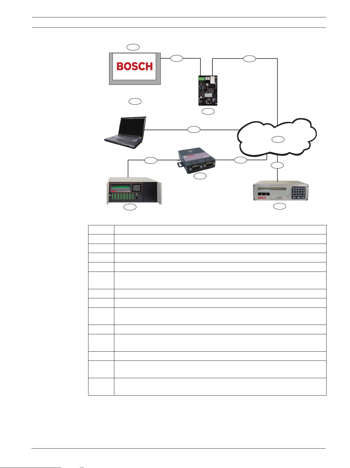
Figure 1.1 System Connections Overview
Callout Description
1 Compatible Bosch control panel
2 Data bus connection between the control panel and the B420
3 B420 Ethernet Communication Module
4 Ethernet connection between B420 and Ethernet network
5 Ethernet network, Local Area Network (LAN), Metropolitan AreaNetwork (MAN),
Wide Area Network (WAN), or Internet
6 Ethernet network connection to the D6100i Communications Receiver
7 Conettix D6100i Communications Receiver/Gateway
8 Ethernet network connection to the D6680/ITS-D6682 (ITS-D6682 shown)
Ethernet Network Adapter
9 Conettix D6680/ITS-D6682 (ITSD6682 shown) Ethernet Network Adapter
10 Connection from ITS-D6682 to the COM4 Port on the D6600
CommunicationsReceiver/Gateway COM4 Port
11 Conettix D6600 Communications Receiver/Gateway
12 Ethernet network connection between the host computer Ethernet network
interface card (NIC) and the Ethernet network
13 Host PC running RPS, Automation, or the D6200 Programming Administrative
Software
Refer to Figure 1.2, Page 6 for an overview of the B420.
Bosch Security Systems, Inc. Installation and Operation Guide F01U215236 | 02 | 2011.11
6 en | Introduction Ethernet Communication Module
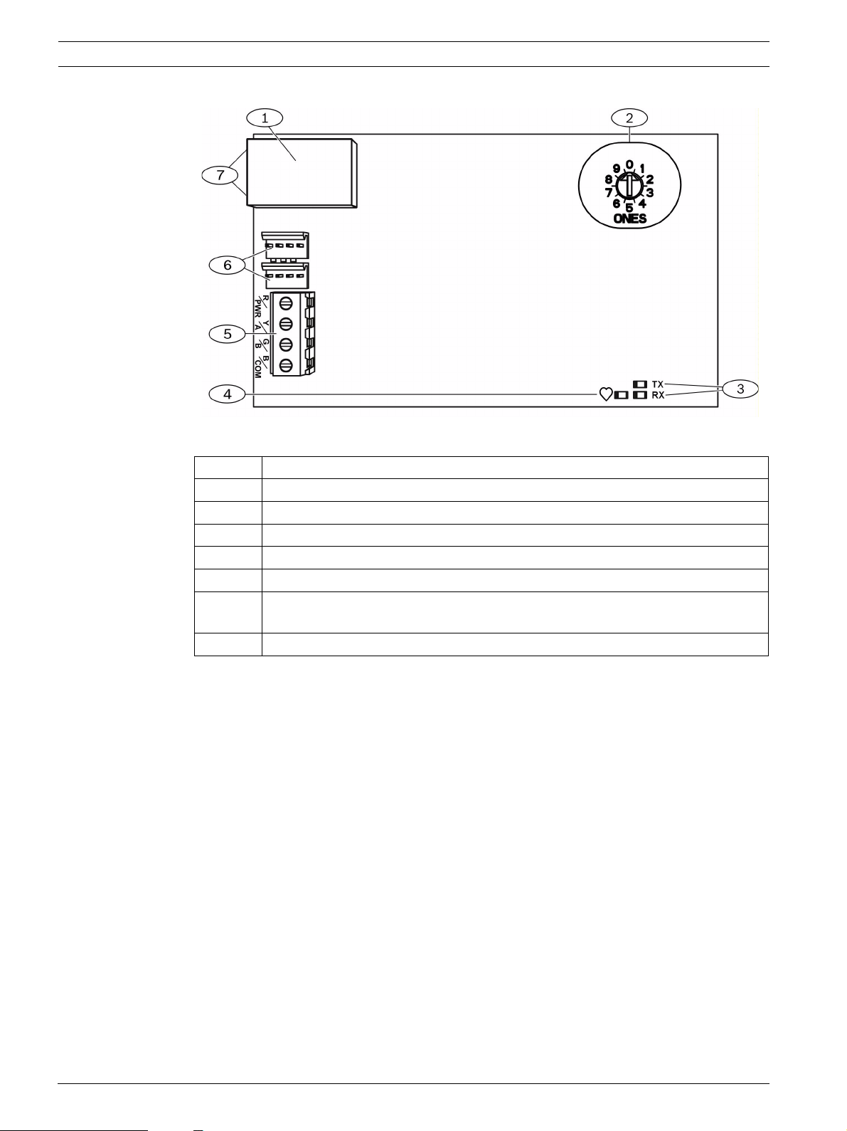
Figure 1.2 B420 Network Interface Module
Callout Description
1 Ethernet RJ-45 port
2 Address switch
3 Data BUS communication LEDs (TX and RX)
4 Heartbeat LED
5 Terminal strip (to control panel)
6 Interconnect wiring connectors P2 and P3 (to control panel or other compatible
modules)
7 Ethernet Status LEDs (on connection side of the RJ45 jack)
F01U215236 | 02 | 2011.11 Installation and Operation Guide Bosch Security Systems, Inc.

Ethernet Communication Module Introduction | en 7
1.4 Technical Specifications
Dimensions (HxWxD) (63.3 mm x 101 mm x 16 mm) (2.49 in x 3.9 in x 0.629 in)
Current (Maximum) – 10BaseT Ethernet: 90 mA max
– 100BaseT Ethernet: 100 mA max
Voltage (Operating) 12 VDC Nominal
Connectors – Control panel: Option or data bus terminals
– LAN/WAN: RJ-45 modular port (Ethernet)
Ethernet Cable – Category 5 or better unshielded twisted pair
– 100 m (328 ft) max length
Interface IEEE 802.3
Data Bus Wire Size 2 mm to 0.65 mm (18 AWG to 22 AWG)
Data Bus Wire Length 150 m (500 ft) - 0.65 mm (22 AWG)
300 m (1000 ft) - 2 mm (18 AWG)
Web Browser Microsoft Internet Explorer 6 or higher; Mozilla Firefox 3 or
higher
Compatible Control Panels – FPD-7024 Version 2.10 or higher
– G Series Version 7.0 or higher
– GV2 Series Version 7.06 or higher
– GV3 Series Version 8.02 or higher
– GV4 Series Version 1.00 or higher
1.5 Certifications
Region Certification Applicable Control Panels
US UL 365 - Police Station Connected Burglar
Alarm Units and Systems
UL 864 - Control Units and Accessories for
Fire Alarm Systems (including NFPA 72)
UL 1610 - Central-Station Burglar-Alarm
Units
FCC Part 15 Class A GV4 Series, GV3 Series, FPD-7024
CSFM - California Office of The State Fire
Marshal
NIST FIPS-197 AES Certification (IP
Communications)
GV4 Series, GV3 Series
GV4 Series, GV3 Series, FPD-7024
GV4 Series, GV3 Series
GV4 Series, GV3 Series, FPD-7024
GV4 Series, GV3 Series, FPD-7024
Bosch Security Systems, Inc. Installation and Operation Guide F01U215236 | 02 | 2011.11

8 en | Installation Ethernet Communication Module
2 Installation
1. Set the rotary switch on the B420 to the appropriate address to ensure proper
communication between device and control panel. Refer to Table 2.1. Refer to Figure 1.2,
Page 6 for the location of the rotary switch.
Control Panels Switch
Position
Web-based configuration
setting
GV4 Series 1 1 SDI2 Automation or RPS,
GV4 Series 2 2 SDI2 Automation or RPS,
GV4 Series, GV3 Series, GV2
Series, G Series, D9412/
D7412/D7212, D9112
GV4 Series, GV3 Series, GV2
Series, G Series, D9412/
D7412/D7212, D9112
GV4 Series, GV3 Series 5 92 SDI RPS, Reporting
Tab le 2 .1 B420 Rotary Switch Settings
NOTICE!
Web browser configuration of the module address can only be done when the switch is in the
’0’ position.
0 Configurable Any Web-based
3 80 SDI Automation
4 88 SDI RPS, Reporting
B420 Address Bus Type Function
Configuration
Reporting
Reporting
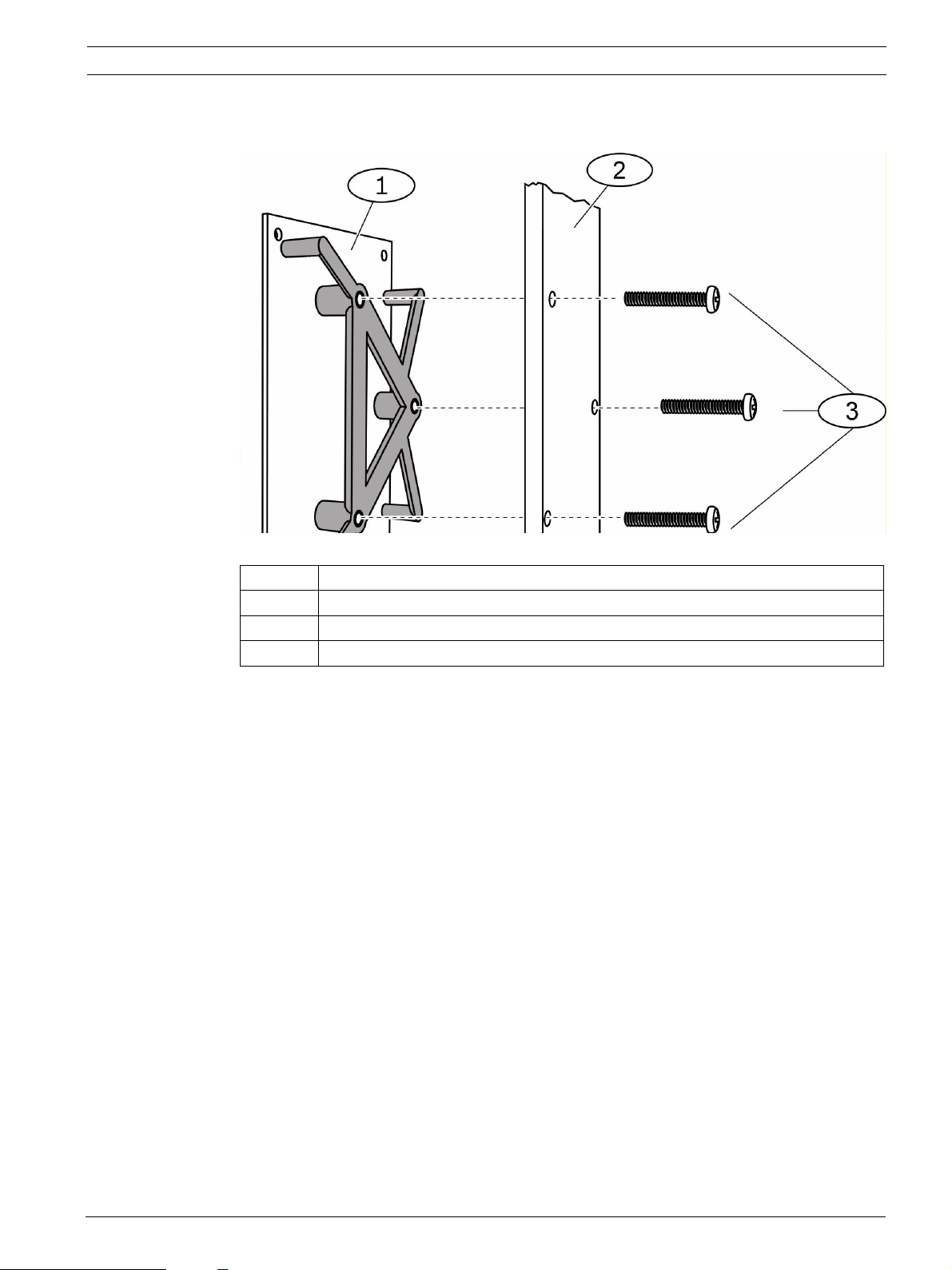
2. Mount the B420 inside the enclosure using any of the standard three-point mounting
patterns. Secure the B420 to the enclosure using the supplied screws. Refer to
Figure 2.1, Page 9.
NOTICE!
The enclosure that contains the B420 can be no further than 20 ft from the control panel
enclosure and must be located in same room. The wiring between enclosures must be
contained within metal conduit.
F01U215236 | 02 | 2011.11 Installation and Operation Guide Bosch Security Systems, Inc.
Ethernet Communication Module Installation | en 9
Figure 2.1 Mounting the B420
Callout Description
1 B420 with mounting bracket installed
2Enclosure
3 Mounting Screws (3)
3. Run the wiring connections from the B420 to the data bus terminals on the compatible
control panel. Refer to Figure 2.2, Page 10.
4. Connect the Ethernet cable to the Ethernet port on the B420. Refer to Figure 2.2,
Page 10.
Bosch Security Systems, Inc. Installation and Operation Guide F01U215236 | 02 | 2011.11
 Loading...