

Bosch D7212GV3K7 Installation Manual
Installation Guide
D8128D OctoPOPIT Module

D8128D
Table of Contents
1.0 Introduction .................................................................................................................................... 3
1.1 Document Organization .................................................................................................................................3
1.2 Tips, Important Notes, Cautions, and Warnings ...............................................................................................3
1.3 Listings .........................................................................................................................................................3
1.3.1 Requirements for Fire Initiation Applications .............................................................................................3
2.0 Overview ........................................................................................................................................ 4
2.1 Specifications ................................................................................................................................................4
2.2 Compatible Control Panels and Maximum Number of D8128 Connections ........................................................5
3.0 Installation ...................................................................................................................................... 6
3.1 Setting OctoPOPIT Switches ..........................................................................................................................6
3.1.1 Address Switches ........................................................................................................................................6
3.1.2 Point DIP Switches......................................................................................................................................7
3.2 Mounting the D8128D ....................................................................................................................................7
3.3 Wiring ...........................................................................................................................................................8
3.3.1 Connect the D8128D to the Control Panel using the Terminal Strip ..........................................................8
3.3.2 Wiring Multiple D8128D Modules to the Control Panel using Molex Connectors ................................... 10
3.4 Wiring OctoPOPIT Sensor Loops ................................................................................................................ 10
3.4.1 OctoPOPIT Sensor Loops ........................................................................................................................ 10
3.4.2 Switch Settings for Control Panels .......................................................................................................... 11
Figures
Figure 1: D8128D OctoPOPIT Layout ......................................................................................................................6
Figure 2: Mounting Enclosure ..................................................................................................................................7
Figure 3: Wiring the D8128D to a Control Panel Wired to a D8125 POPEX Module ...............................................9
Figure 4: Wiring Multiple D8128D Modules Using Molex Connectors .................................................................. 10
Figure 5: D8128D Sensor Loops ........................................................................................................................... 10
Tables
Table 1: Document Organization .............................................................................................................................3
Table 2: D8128D Specifications ..................................................................................................................................4
Table 3: Compatible Control Panels and Maximum D8128D Connections ......................................................................5
Table 4: Number of D8128D Modules Used with the D8129 Modules ............................................................................6
Table 5: Terminal Strip Connections .......................................................................................................................8
Table 6: D8128D Address Switch Settings ........................................................................................................... 11
D8128D Installation Guide
F01U070537-07 Page 2 © 2015 Bosch Security Systems, Inc.
D8128D
1.0 Introduction
The D8128D OctoPOPIT Module combines the functions of the D8125 POPEX Module and the D8127/D9127
POPIT Modules to provide eight off-board points (Class B [Style B]) in a single module. You can wire both the
D8128D OctoPOPIT and D8125 POPEX in parallel to the ZONEX Bus Terminals on the same control panel.
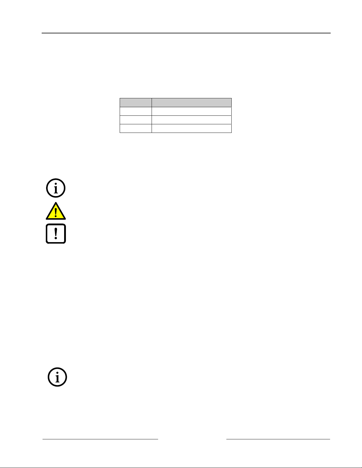
1.1 Document Organization
Table 1 identifies the sections of this document.
Section Description
1 Introduction
2 Overview
3 Installation
Table 1: Document Organization
1.2 Tips, Important Notes, Cautions, and Warnings
Throughout this document, helpful tips, important notes, cautions and warnings are presented for the reader to
keep in mind. These appear different from the rest of the text as follows:
Heed for successful operation and programming. Can also include tips and shortcuts.
Caution the operator that physical damage to the program and/or equipment can occur.
Warn of the possibility of physical damage to the operator, program, and/or equipment.
1.3 Listings
The D8128D is Underwriters Laboratories, Inc. (UL) Listed for Local or Police Connected Burglary Alarm,
Central Station Burglary Alarm, Household Burglary Alarm applications, and Commercial Fire applications
(UL864 and NFPA 72). The D8128D is also suitable for Fire Supervisory applications, such as indicating circuit
supervision using the D192G (D192C) Bell Circuit Supervision Module, sprinkler supervision, and valve tamper
protection.
1.3.1 Requirements for Fire Initiation Applications
You can connect non-powered, fire initiating devices such as pull-stations, heat detectors, and UL Listed fourwire smoke detectors directly to the D8128D point inputs.
The D125B Dual Powered Loop Interface Module or the D129 Dual Class A Module zone outputs can be
connected directly to the D8128D point inputs. Use the D125B to connect two-wire smoke detectors. Generally,
the D129 is used for connecting waterflow switches.
The D125B or D129 and the OctoPOPIT can be mounted in the same enclosure with the control panel or in a
separate enclosure connected to the control panel’s enclosure by conduit no more than 20 ft (6 m) long.
The D7212GV4, D7212GV3, D7212GV2, and D7212G Control Panel is not listed for commercial
fire applications.
D8128D Installation Guide
F01U070537-07 Page 3 © 2015 Bosch Security Systems, Inc.

D8128D
2.0 Overview
2.1 Specifications
Compatible Panels Refer to Table 3.
Power
Requirements
Voltage: 12 VDC nominal
Current: Standby (supervised): 25 mA maximum
Environmental
Considerations
Operating
Temperature:
Relative
Humidity:
Loop
End-of-Line
(EOL)
Resistance:
Wiring
Resistance:
Response Time:
Cabling
Burglary
Applications:
Fire Applications: Use UL Listed fire rated cable approved by the AHJ when connecting fire-
Alarm (all points shorted): 50 mA maximum
+32°F to +120°F (0°C to +49°C)
0% to 93%
1 kΩ
100 Ω maximum
Approximately 1 sec. OctoPOPIT sensor loops are supervised with a 1 kΩ EOL
resistor, D105BL or D105FL, for fire supervisory applications.
D8128D OctoPOPITs can be installed up to 200 ft (61 m) 4 Ω maximum from
the control panel using standard 4-conductor 22 AWG (0.8 mm) wire.
initiating or fire-supervisory devices to the D8128D.
You can locate the D8128D OctoPOPITs up to 200 ft (61 m), 4 Ω maximum
from the control panel. You must mount the D8128D in a D8109 or D8108A
Enclosure. When a D125B or D129 is required, mount it in the same enclosure
as the D8128D OctoPOPIT.
Control Panel Wiring Connection Requirements (Maximum Wire
Resistance: 4 Ω)
Maximum Distance Wire Size
200 ft 22 AWG
200 ft 18 AWG
60 m 0.6 mm
60 m 1.0 mm
Table 2: D8128D Specifications
D8128D Installation Guide
F01U070537-07 Page 4 © 2015 Bosch Security Systems, Inc.
 Loading...