

Page 1
1 | Overview
The B520 Auxiliary Power Supply Module provides up to 2A of
12 VDC power for Fire and Burglar standby power applications.
For Burglar applications, an additional 2A of alarm power is
available, allowing 2A of standby current and up to 4A of alarm
current. You can connect more than one Aux Power Supply
module to the control panel by wiring them in parallel. Refer to
Figure 3.6.
The module’s address switches provide a tens and ones value
for the module’s address. For single-digit address numbers 1
through 9, set the tens switch to 0 and the ones digit to the
appropriate number. Figure 2.1 shows the address switches
setting for addresses 12.
3 | Installation
After you set the address switches for the proper address,
install the module in the enclosure, and then wire it to the
control panel, SDI2 expansion modules,
and/or other 12 VDC devices.
NOTICE!
Remove all power (AC and battery) before making any
connections. Failure to do so might result in personal
injury and/or equipment damage.
3.1 | Mount the module in the enclosure
(models B10, D2203, AE1, and AE2)
3.1.1 | Wire the grounding wire
(models B10, D2203, AE1, and AE2)
Insert the grounding wire lug onto the bolt, and secure it
with a nut and a washer. Insert the other end of grounding
wire onto the enclosure door hinge. Refer to Figure 3.2.
3.2.2 | Mount the module onto the
mounting plate
Insert the plastic mounting clips onto the appropriate
standoff locations on the mounting plate. Place the B520
against the plastic mounting clips and then secure it using
the supplied mounting screws. Refer to Figure 3.4.
7
7
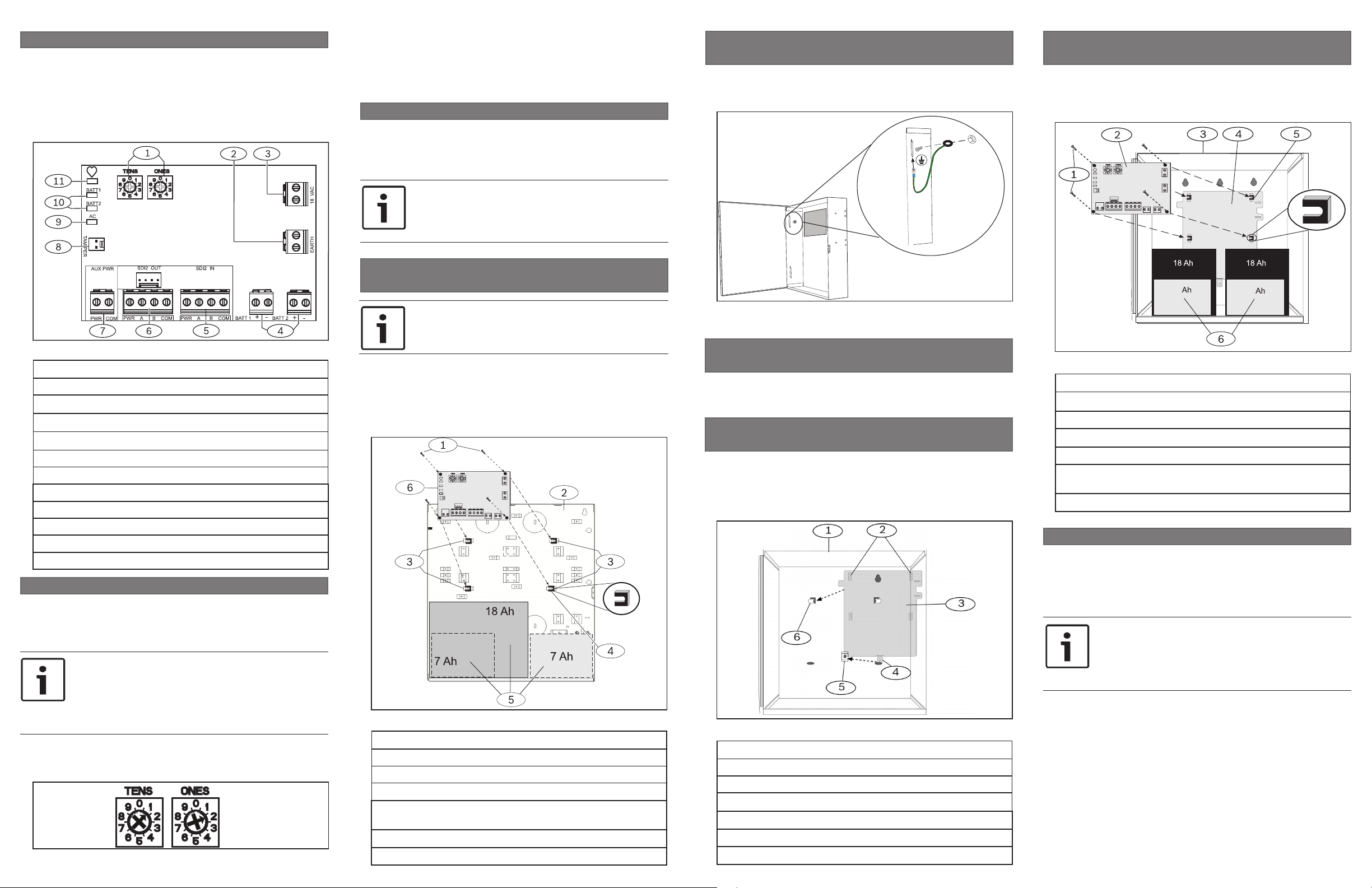
Figure 1.1: Board overview
Callout ― Description
1 ― Address switches
2 ― EARTH ground connector terminal
3 ― 18 VAC transformer input terminal (TR1850)
4 ― BATT 1 and BATT 2 terminals
5 ― SDI2 IN terminals (from control panel)
6 ― SDI2 OUT terminals and interconnect wiring connector
7 ― Auxiliary power terminals
8 ― Tamper switch connector
9 ― AC LED (green)
10 ― BATT 1 and BATT 2 LEDs (green)
11 ― Heartbeat LED (blue)
2 | SDI2 address settings
Two address switches determine the address for the B520
Auxiliary Power Supply Module. The control panel uses the ad-
dress for communications. Use a slotted screwdriver to set the
address switches.
NOTICE!
The module reads the address switch setting only
during power up. If you change the switches after
you apply power to the module, you must cycle the
power to the module in order for the new setting to
be enabled.
Set the address switches per the control panel conguration. If
multiple B520 modules reside on the same system, each B520
module must have a unique address.
Figure 2.1: Address switches
NOTICE!
Do not use B10 or D2203 enclosures for Commerical
Fire applications.
Insert the plastic mounting clips onto the appropriate
standoff locations inside the enclosure. Refer to Figure 3.1.
Mount the module onto the plastic mounting clips and then
secure it using the supplied mounting screws. B10, D2203,
AE1, and AE2 enclosure installations can hold up to two 7 Ah
batteries, or one 18 Ah battery.
Figure 3.1: Mounting the module in the enclosure
Callout ― Description
1 ― Mounting screws (4)
2 ― B10, D2203, AE1, and AE2 enclosures (back panel)
3 ― Standoff locations
4 ― Plastic mounting clips (4) (snapped onto enclosure
standoffs)
5 ― Batteries (up to two 7 Ah or one 18 Ah batteries)
6 ― B520 module
Figure 3.2: Wiring the grounding wire (B10 shown)
3.1 | Mount the module in the enclosure
(model D8103)
Mounting in the D8103 enclosure requotes the B12 mounting
plate.
3.1.1 | Mount the B12 mounting plate
in the enclosure (model D8103)
Place the B12 mounting plate in the back of the D8103
enclosure, and set the tabs of the D8103 into the
enclosure’s two mounting skirt hooks. Secure the lock
down tab to the skirt mounting hole with the provided
screw. Refer to Figure 3.3.
Figure 3.3: Mounting plate onto the D8103 enclosure
Callout ― Description
1 ― D8103 enclosure (also applicable for BATB-40)
2 ― Support posts (2)
3 ― Mounting plate
4 ― Lock down tab
5 ― Plate mounting hole
6 ― Mounting plate hooks (2)
Figure 3.4: Mounting the B520 onto the mouting plate
Callout ― Description
1 ― Mounting screws (4)
2 ― B520 module
3 ― D8103 Enclosure (applicable for BATB-40 as well)
4 ― B12 mounting plate
5 ― Plastic mounting clips (4) (fastened to the mounting
plate standoffs)
6 ― Batteries (holds up to two 7 Ah or two 18 Ah batteries)
3.3 | Wire the earth ground terminal
To help prevent damage from electrostatic charges or other
transient electrical surges, connect the system to earth ground
before making other connections. Recommended earth ground
references are a grounding rod or a cold water pipe. When
grounding, run wire as close as possible to grounding device.
NOTICE!
Do not use telephone or electrical ground for the
earth ground connection. Use 14 AWG (1.8 mm)
to 16 AWG (1.5 mm) wire when making the
connection.
Page 2
2
1
18 VAC
EARTH
3
Figure 3.5: Wiring the earth ground connection
Callout ― Description
1 ― B520 module
2 ― 14 AWG - 16 AWG (1.8 mm - 1.5 mm) wire
3 ― Ground device (grounding rod or cold water pipe)
3.4 | Mount and wire the tamper switch
You can connect an enclosure optional door tamper switch
for one module in an enclosure.
Installing the optional tamper switch:
1. Mount the ICP-EZTS Tamper Switch (P/N: F01U009269)
into the enclosure’s tamper switch mounting location. For
complete instructions, refer to EZTS Cover and Wall Tamper
Switch Installation Guide (P/N: F01U003734).
2. Plug the tamper switch wire onto the module’s tamper
switch connector. Refer to Figure 1.1.
3.5 | Wire to the control panel
When you wire a B520 to a control panel, use the terminal
strip labeled SDI2 IN with PWR, A, B, and COM to wire to the
designated terminals, according to the compatible control
panel conguration. Ensure the wiresattache properly.
Figures 3.5 through 3.8 for all wiring congurations.
Refer to
Figure 3.6: Installing multiple modules
Callout ― Description
1 ― Compatible Bosch control panel SDI2 bus connection
2 ― B520 module (Refer to the control panel’s Installation
and System Reference Guide for multiple module
congurations.)
3.6 | Wire to powered devices
After wiring the module to the control panel, wire it to the
powered devices.
3.6.1 | Wire to powered SDI2 devices
When you wire the output of a B520 to a SDI2 module, you can
use either the terminal strip of the SDI2 OUT terminal labeled
with PWR, A, B, COM, or you can use the interconnect wiring
connectors. Refer to Figure 3.7.
Figure 3.8: Wiring the AUX power terminal to devices
Callout ― Description
1 ― Compatible Bosch peripheral device
2 ― B520 module
NOTICE!
When used to power a local security annunciator
(e.g. bell) or a DACT, the B520 must be installed in
the D8108A Attack Resistant Enclosure.
3.7 | Wire to the batteries
You must wire the B520 to BATT 1 for proper operation of
standby power for the B520 module. Wiring the second
battery (BATT 2) is optional. If a control panel is congured
for two batteries as the standby power source, then BATT 2 is
also required for proper operation. BATT 2 must have the same
capacity, and same rating as BATT 1. Maximum Standby power
cannot exceed 36 Ah. Refer to Figure 3.9.
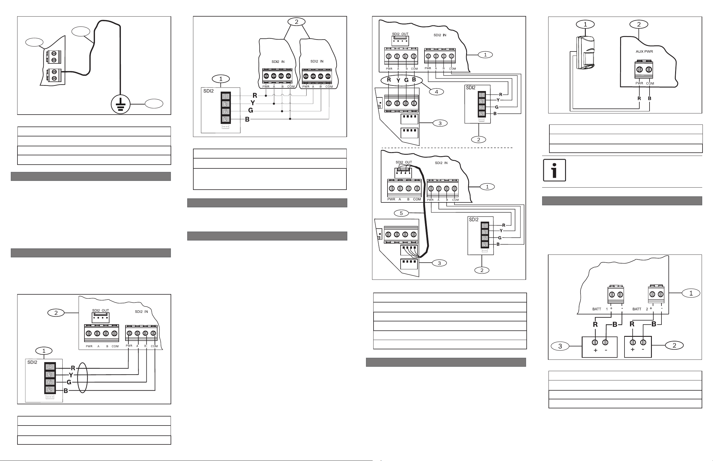
Figure 3.7 Using terminal strip or interconnect cable wiring
Figure 3.6: Wiring the module to the control panel
Callout ― Description
1 ― Compatible Bosch control panel SDI2 bus connection
2 ― B520 module
Callout ― Description
1 ― B520 module
2 ― Compatible Bosch control panel SDI2 bus connection
3 ― SDI2 module
4 ― Terminal strip wiring (SDI2)
5 ― Interconnect cable (P/N: F01U079745) (included)
3.6.2 | Wire to powered non-SDI2 devices
The AUX PWR power terminals provide auxiliary power
capabilities for additional peripheral devices such as PIR’s
and Keypads. When you wire the B520 to an added peripheral
device, use the AUX PWR terminal strip labeled with PWR and
COM. Refer to Figure 3.8.
Figure 3.9 Wiring the batteries
Callout ― Description
1 ― B520 module
2 ― Battery 2 (BATT 2) - (12 V nominal lead acid)
3 ― Battery 1 (BATT 1) - (12 V nominal lead acid)
Page 3

3.7 | Wire to the transformer
You must wire the plug-in transformer to 18 VAC B520 for
proper operation of the B520 module. Refer to Figure 3.10.
Figure 3.10: Wiring the transformer
Callout ― Description
1 ― B520 module
2 ― TR1850 plug-in transformer
4 | Battery congurations and calculations
To determine the battery standby usage, reference the Table 4.1.
Battery Size (AH’s) for Commercial Fire Applications:
To select the proper battery size, compare the current
calculations from Table 5.1 against the highest current
available for the standby hours required. If the current from
“Total A” or “Total B” exceeds the highest value in that
column, then a second B520 is required to split the current
load.
Battery Size (AH’s) for Burglar Applications:
To select the proper battery size, compare the current
calculations from Table 5.1 against the highest current
available for the standby hours required. If the current from
“Total A” exceeds the highest value in that column, or the
current from “Table B” exceeds 4A, then a you must split the
current load with a second B520.
NOTICE!
The battery terminals and wire are not power limited.
A 0.25 in (6.4 mm) space must be maintained between
the battery terminals, battery wiring, and all other
wiring. Battery wiring cannot share the same conduit,
conduit ttings, or conduit knock-outs with other
wiring. All external connections are power-limited
except battery terminals. All external connections are
supervised.
A
Standby current (mA)
Maximum current (mA)
Model # Quantity
used
B208 35 x Quantity = 35 x Quantity =
B308* 22 x Quantity = 22 x Quantity =
B420** 100 x Quantity = 100 x Quantity =
B426 100 x Quantity = 100 x Quantity =
B820 100 x Quantity = 110 x Quantity =
D185 245 x Quantity = 300 x Quantity =
D1255/D1255B 106 x Quantity = 206 x Quantity =
D1256/D1257 106 x Quantity = 206 x Quantity =
D1255RB 106 x Quantity = 225 x Quantity =
D1256RB 106 x Quantity = 225 x Quantity =
D1257RB 106 x Quantity = 225 x Quantity =
D1260/D1260B 140 x Quantity = 250 x Quantity =
B920 35 x Quantity = 85 x Quantity =
B930 35 x Quantity = 85 x Quantity =
D720 20 x Quantity = 100 x Quantity =
D8128D 25 x Quantity = 50 x Quantity =
D8129*** 20 x Quantity = 20 x Quantity =
D9210C**** 110 x Quantity = 110 x Quantity =
DX4010V2***** 50 x Quantity = 55 x Quantity =
DX4020 80 x Quantity = 84 x Quantity =
ITS-DX4020-G 65 x Quantity = 200 x Quantity =
Other devices
* (digital section = 22 mA) + (Qty of relays x 16 mA) = total current. (Add 16 mA for each relay being used).
** 10BaseT Ethernet: 90 mA max, 100BaseT Ethernet: 100 mA max.
*** The In Alarm calculation for the D8129 Is: 20 X Qty + (16.25 x number of relays).
**** Use 110 mA + reader current. Do not exceed 260 mA.
***** UL requires the DX4010V2 be used for programming only.
Table 4.1: Current rating chart for standby calculations
Enclosures BATT 1 BATT 2 BATT 1 BATT 2
D2203, B10, AE1, AE2 18 Ah N/A 7 Ah 7 Ah (optional)
D8103, BATB-40 18 Ah 18 Ah (optional) 7 Ah 7 Ah (optional)
Table 4.2: Typical battery conguration
4 8 24 24 48 60 72 80
24 24 24 48 48 48 72 72
Rechargeable battery size (AH) Maximum output standby current
7 1.135 0.575 0.100 0.169
14 (+2 7 Ah) 1.600 1.100 0.330 0.403 0.176 0.131 0.101
18 1.800 1.220 0.460 0.536 0.243 0.184 0.145 0.126
36 (+2 18 Ah) 2.000 1.790 0.710 0.950 0.520 0.424 0.345 0.306
Each unit Quantity Total Each unit Quantity Total
Total A = Total B =
Battery conguration #1 Battery conguration #2
Standby hours
Recharge Hours
B
In alarm
5 | LED descriptions
The B520 module includes the following on-board LEDs to
assist with troubleshooting issues (refer to Figure 1.1 for the
location of the LEDs):
– Heartbeat (system status). Refer to Table 5.1.
– BATT 1 and BATT 2. Refer to Table 5.2.
– AC IN. Refer to Table 5.3.
For troubleshooting steps based on the LEDs, refer to
Section 7.
Flash pattern Function
Flashes once
every 1 sec
3 quick ashes
every 1 sec
On Steady LED trouble state: Module is not
Off
Table 5.1: Heartbeat (blue) LED descriptions
Flash pattern Function
Flashes once
every 1 sec
3 quick ashes
every 1 sec
On Steady Normal state. Indicates normal operation
Off Battery missing.
Table 5.1: BATT 1 and BATT 2 (green) LEDs descriptions
Flash pattern Function
Flashes once
every 1 sec
3 quick ashes
every 1 sec
On Steady Normal state. Indicates normal operation
Table 5.1: AC (green) LED descriptions
Normal state: Indicates normal operation
state.
Communication error state: Indicates
(the module is in a “no communication
state”) resulting in an SDI2
communication error.
powered (for OFF Steady only), or some
other trouble condition prohibits the
module from controlling the heartbeat
LED.
Low battery.
Battery charger failure.
state.
Low or failed AC.
Battery test performing.
state.
Table 4.3: B520 Auxiliary Power Supply Module battery standby chart
Page 4

6 | Show the rmware version
9 | Certications
11 | Next
10 | Specications
To show the rmware version using an LED ash pattern:
– If the optional tamper switch is installed:
With the enclosure door open, activate the tamper switch
(push and release the switch).
– If the optional tamper switch is NOT installed: Momentarily
short the tamper pins.
Refer to Figure 6.1 for an example of ash patterns.
Figure 6.1: Firmware LED ash patterns
When the tamper switch is activated (closed to open), the
heartbeat LED stays OFF for 3 sec before indicating the
rmware version. The LED pulses the major, minor, and
micro digits of the rmware version, with a 1 sec pause after
each digit.
Flashing patterns do not start until the tamper is open
(short is removed). The following is an example: The version
1.4.3 would be shown as LED ashes:
[3 second pause] *___****___*** [3 second pause, then
normal operation].
7 | Troubleshooting
Flash pattern Corrective action
Heartbeat – 3 quick
ashes every 1 sec
BATT 1 (BATT 2) – 3
quick ashes every
1 sec
AC Flashing Measure the AC voltage before
Table 7.1: LED troubleshooting patterns
1. Check wiring, ensure secure
connection.
2. Control panel might be
programmed incorrectly.
3. Address switches do not match
the control panel. Verify address
selections.
Measure the voltage at the battery
terminals. If the voltage is above
13.3 VDC, and is a fully charged
battery, the condition restores once
some of the energy is drained from
the battery. If the battery voltage is
low, the B520 might be damaged.
and after the transformer. If there
is voltage before and none after,
replace the transformer.
8 | Conguration
Use Remote Programming Software (RPS) to program the
control panel to work with the module. For programming
parameter descriptions, options, and defaults, refer to RPS Help.
Region
US UL 365 - Police Station Connected Burglar Alarm
Units and Systems
UL 609 - Local Burglar Alarm Units and Systems
UL 636 - Hold Up Alarm Units
UL 864 - Control Units and Accessories for Fire
Alarm Systems
UL 985 - Household Fire Warning System Units
UL 1023 - Household Burglar Alarm System
Units
UL 1076 - Proprietary Burglar Alarm Units and
Systems
UL 1610 - Central Station Burglar Alarm Units
FCC Part 15 Class B
Canada CAN/ULC S303 - Local Burglar Alarm Units and
Systems
CAN/ULC S304 - Signal Receiving Centre and
Premise Alarm Control Units
CAN/ULC S545 - Residential Fire Warning Con-
trol System
ULC-ORD C1023 - Household Burglar Alarm
System Units
ULC-ORD C1076 - Propriety Burglar Alarm Unit
and Systems
ICES-003 - Digital Apparatus
Dimensions 4.5 in x 6.94 in x 1.15 in
(11.43 cm x 17.62 cm x 2.9 cm)
Output voltage (rated
range)
AC line input voltage
frequency
Current available
(maximum)
Current drawn from
the control panel
Battery Input 2 separate 12 V lead acid batter-
Operating temperature +32°F to +120°F (0°C to +49°C)
Relative humidity 5% to 93% at +90°F (+32°C) non-
Storage temperature -4° to 140° F (-20° to 60°C)
Transformer power
supply
Transformer wiring 12-18 AWG
Terminal wire size 12 AWG to 22 AWG
SDI2 wiring *Maximum distance - Wire size:
Compatibility B5512/B4512/B3512 control
Usage Intended for indoor/dry use
Copyright
This document is the intellectual property of Bosch Security
Systems, Inc. and is protected by copyright. All rights reserved.
Trademarks
All hardware and software product names used in this
document are likely to be registered trademarks and must be
treated accordingly.
Bosch Security Systems, Inc. product manufacturing dates
Use the serial number located on the product label and refer to
the Bosch Security Systems, Inc. website at
http://www.boschsecurity.com/datecodes/.
11.5 - 12.2 VDC (special
application)
120 VAC +10/-15% (60 Hz) 0.5 A
2.0 A SDI2 Out and AUX Power
(combined)
(up to 4.0 A of alarm current for
Burglar Applications)
15 mA
ies (7-18 Ah) 4.0 A max available
from charger.
condensing
TR1850 - (18 VAC, 50 VA)
TR1850-CA - (18 VAC, 50 VA) for
Canada
(2 mm to 0.65 mm)
(Unshielded wire only)
1000 ft (305 m) - 22 AWG (0.65
mm)
1000 ft (305 m) - 18 AWG (2 mm)
*Maximum wiring distance from the
panel to the last SDI2 module can
not exceed 1000 ft.
panels
GV4 Series control panels
D8103 Enclosure (requires B12)
D8108A Attack Enclosure
(requires B12)
B10 Enclosure
D2203 Enclosure
BATB-40 Enclosure (requires B12)
AE1/AE2 Enclosure
Auxiliary Power Supply Module
B520
en Installation Guide
Bosch Security Systems, Inc.
130 Perinton Parkway
Fairport, NY 14450
USA
www.boschsecurity.com
© 2013 Bosch Security Systems, Inc. F.01U.265.445 | 02 | 2013.08
 Loading...