

Page 1

Control Panels
B6512/B5512/B4512/B3512 (B5512E/B4512E/B3512E)
en
Installation Manual
Page 2

Page 3

Control Panels Table of contents | en 3
Table of contents
1
1.1 Listings and approvals 8
1.1.1 UL 8
1.1.2 ULC 8
1.1.3 Security Industry Association (SIA) 8
1.1.4 Department of Defense (DoD) 8
1.1.5 Department of Energy 8
1.1.6 California State Fire Marshal (CSFM) 8
1.1.7 National Institute of Standards and Technology (NIST) 8
1.1.8 Federal Communications Commission (FCC) Rules 9
1.1.9 Industry Canada (IC) 9
1.2 Safety 9
1.2.1 Lightning 10
1.2.2 Power 10
2
2.1 About documentation 12
2.1.1 Related documentation 12
2.2 Bosch Security Systems, Inc. product manufacturing dates 14
3
4
5
5.1 Install the enclosure and wiring label 18
5.2 Install the control panel 19
5.2.1 Mount the control panel 19
5.2.2 Connect earth ground 20
5.2.3 Configure OUTPUT A using the jumper 20
5.3 Control panel to module wiring overview 21
6
6.1 Primary (AC) power 22
6.2 Secondary (DC) power 22
6.2.1 Install the battery 22
6.2.2 Battery maintenance 24
6.2.3 Battery supervision 24
6.2.4 Battery discharge and recharge schedule 24
6.3 B520 Auxiliary Power Supply 24
6.3.1 SDI2 address settings 25
6.3.2 Supervision 25
6.3.3 Auxiliary power supply trouble conditions 25
6.3.4 Installation and control panel wiring (B520) 25
6.3.5 Powered device and battery wiring 26
7
7.1 B430 Plug-in Telephone Communicator 28
7.1.1 Supervision 28
7.1.2 Installation and module wiring (B430) 28
7.1.3 Diagnostic LEDs 29
7.2 Phone jack location 29
7.3 Telephone line monitor 30
7.4 Called party disconnect 30
Certifications, approvals, listings, and safety 8
Introduction 12
System overview 15
Installation checklist 16
Control panel installation 18
Power supply 22
Telephone communications 28
Bosch Security Systems, Inc. Installation Manual 2017.04 | 15 | F.01U.287.180
Page 4

4 en | Table of contents Control Panels
7.5 Communication failure 31
8
IP communications 32
8.1 On-board Ethernet connection 32
8.1.1 Supervision 32
8.1.2 Local RPS programming 32
8.1.3 On-board Ethernet diagnostic LEDs 33
8.2 Conettix Plug-in Cellular Communicators 34
8.2.1 Supervision 34
8.2.2 Installation and module wiring (B44x) 34
8.2.3 Signal strength and diagnostic LEDs 35
8.3 B426 Ethernet Communication Module 36
8.3.1 Address and emulation settings 36
8.3.2 Supervision 36
8.3.3 B426 module faults 36
8.3.4 Local RPS programming 37
8.3.5 Installation and control panel wiring (B426) 37
8.3.6 Diagnostic LEDs 38
8.4 B450 Conettix Plug-in Communicator Interface 40
8.4.1 SDI2 address settings 40
8.4.2 Supervision 40
8.4.3 Installation and control panel wiring (B450) 40
8.4.4 Diagnostic LEDs 41
8.5 Compatible receivers for IP communication 42
9
Keypads, keyswitches, keyfobs and transmitters 44
9.1 Keypads 44
9.1.1 B915 Basic Keypad 44
9.1.2 B920 Two-line Alphanumeric Keypad 44
9.1.3 B921C Two-line Capacitive Keypad with Inputs 44
9.1.4 B930 ATM Style Alphanumeric Keypad 44
9.1.5 B942 Touch Screen Keypad 44
9.1.6 Shortcuts and custom functions 45
9.1.7 Address settings 45
9.1.8 Supervision 45
9.1.9 Installation and control panel wiring (keypads) 45
9.1.10 Sensor loops overview and wiring (B921C/B942/B942W only) 46
9.1.11 Output wiring (B942/B942W only) 47
9.1.12 Troubleshooting 47
9.2 Keyswitches 47
9.2.1 Operation 47
9.2.2 Installation and control panel wiring (keyswitches) 48
9.3 RADION keyfobs and Inovonics pendant transmitters 48
10
On-board outputs 50
10.1 Circuit protection 50
10.2 Total available power 50
10.3 Open collector outputs 50
10.4 Continuous power outputs 51
11
Off-board outputs 52
11.1 B308 Octo-output Module 52
11.1.1 SDI2 address settings 52
2017.04 | 15 | F.01U.287.180 Installation Manual Bosch Security Systems, Inc.
Page 5

Control Panels Table of contents | en 5
11.1.2 Supervision 52
11.1.3 Installation and control panel wiring (B308) 53
12
On-board points 54
12.1 Point sensor loops 54
12.1.1 Single EOL (and no EOL) resistor circuit style 54
12.1.2 Dual EOL resistor circuit style 55
12.2 Point response time 56
13
Off-board points 57
13.1 B208 Octo-input Module 57
13.1.1 SDI2 address settings 57
13.1.2 Supervision 57
13.1.3 Installation and control panel wiring (B208) 57
13.1.4 Sensor loops overview and wiring 58
13.2 Test off-board points 61
13.3 Extra Point events 61
13.4 Missing point conditions 61
14
Wireless modules 62
14.1 B810 receiver 62
14.1.1 SDI2 address settings 62
14.1.2 Supervision 62
14.1.3 Installation and control panel wiring (B810) 62
14.2 B820 SDI2 Inovonics Interface Module 63
14.2.1 SDI2 address settings 63
14.2.2 Supervision 63
14.2.3 Installation and control panel wiring (B820) 63
15
Access control 65
15.1 B901 65
15.1.1 Address settings 65
15.1.2 Supervision 65
15.1.3 Installation and control panel wiring (B901) 65
15.2 Card reader wiring 66
16
Program and test the control panel 67
16.1 Program the control panel 67
16.2 Perform walk tests 67
16.2.1 Fire walk test 67
16.2.2 Intrusion walk test 67
16.2.3 Service walk test 68
16.2.4 Invisible walk test 68
17
18
Control panel board overview 70
System wiring diagrams 72
18.1 System wiring overview 72
18.2 Battery lead supervision wiring 74
18.3 2-wire smoke wiring (B201) 75
18.4 2-wire smoke wiring (D125B) 76
18.5 Notification appliance circuit wiring 76
18.6 SDI2 devices general system wiring 78
18.6.1 SDI2 bus wiring recommendations 78
18.7 Wiring label 81
19
Approved applications 82
Bosch Security Systems, Inc. Installation Manual 2017.04 | 15 | F.01U.287.180
Page 6

6 en | Table of contents Control Panels
19.1 Optional compatible equipment 82
19.1.1 Burglar applications 82
19.1.2 Bank safe and vault applications 82
19.1.3 Fire applications 85
19.1.4 Enclosures 86
19.2 Combination fire and intrusion alarm systems 87
19.3 Compatible UL listed components 87
19.4 Standby battery requirements and calculations 89
19.4.1 Household Fire Warning equipment 91
19.5 UL 365 - Police Station Connected Burglar Alarm Units and Systems 92
19.6 UL 636 - Holdup Alarm Units and System 92
19.7 Required values to achieve 180s (ULC)/200s (UL) supervision interval 92
19.8 ULC 93
20
Keypad Installer menu 94
20.1 [1] Program menu (Programming) 100
20.1.1 [1] Reporting > [1] Phone menu parameters 100
20.1.2 [1] Reporting > [2] Network menu parameters 101
20.1.3 [1] Reporting > [3] Routing menu parameters 102
20.1.4 [1] Reporting > [4] Personal Note menu parameters 103
20.1.5 [2] Network > [1] Ethernet > (choose the bus module or on-board) > [1] Module
104
Parameters menu
20.1.6 [2] Network > [1] Ethernet > (choose the bus module or on-board) > [2] Address
105
Parameters menu
20.1.7 [2] Network > [1] Ethernet > (choose the bus module or on-board) > [3] DNS
106
Parameters menu
20.1.8 [2] Network > [2] Cellular > (choose the SDI2 cellular module or plug-in module) 106
20.1.9 [3] RPS > [1] RPS Passcode menu parameters 107
20.1.10 [3] RPS > [2] RPS Phone Number menu parameters 108
20.1.11 [3] RPS > [3] RPS IP Address menu parameters 108
20.1.12 [3] RPS > [4] RPS Port Number menu parameters 108
20.1.13 [4] Area Options menu parameters 108
20.1.14 [5] Keypad menu parameters 110
20.1.15 [6] Users menu parameters 111
20.1.16 [7] Points menu parameters 112
20.1.17 [8] Disable Programming menu 118
20.2 [2] Wireless menu 119
20.2.1 [1] RF Point Menu> [1] Enroll Point RFID 119
20.2.2 [1] RF Point Menu> [2] Replace Point RFID 119
20.2.3 [1] RF Point Menu> [3] Remove Point RFID 119
20.2.4 [2] RF Repeater Menu > [1] Add Repeater 120
20.2.5 [2] RF Repeater Menu > [2] Replace Repeater 120
20.2.6 [2] RF Repeater Menu > [3] Remove Repeater 120
20.2.7 [3] RF Diagnostic Menu > [1] RF Points 120
20.2.8 [3] RF Diagnostic Menu > [2] RF Repeater Menu 121
20.3 [3] Diags menu 121
20.3.1 [1] Wireless 121
20.3.2 [2] Network menu 122
20.3.3 [3] Cellular menu 122
20.3.4 [4] IP Camera 122
2017.04 | 15 | F.01U.287.180 Installation Manual Bosch Security Systems, Inc.
Page 7

Control Panels Table of contents | en 7
20.3.5 [5] Cloud 123
20.4 [4] Service Bypass (Serv Byp) menu 123
20.5 [5] Versions menu 123
20.6 [6] Cloud menu 124
21
Specifications 125
21.1 Wire requirements 127
22
Appendix 128
22.1 Address settings 128
22.1.1 B208 address settings 128
22.1.2 B308 address settings 128
22.1.3 B901 address settings 129
22.1.4 B91x address settings 129
22.2 Reporting and device number information 130
22.2.1 Report format definitions 130
22.2.2 SDI2 address information 139
22.2.3 Device numbers (zzz, dddd) 139
22.2.4 Communication Trouble device numbers (zzzz) 140
22.2.5 Special User IDs (uuuu, iiii) 140
22.2.6 Keypad alarm virtual point numbers (ppp, pppp) 140
22.3 AutoIP 141
Bosch Security Systems, Inc. Installation Manual 2017.04 | 15 | F.01U.287.180
Page 8

8 en | Certifications, approvals, listings, and safety Control Panels
1 Certifications, approvals, listings, and safety
This section provides certification and approval listings and safety information.
1.1 Listings and approvals
This document includes the section Approved applications, page 82. Refer to this section for
guidelines on installing the control panels in Underwriters Laboratories Inc. (UL) and firespecific applications.
1.1.1 UL
Listed for:
– UL 365 - Police Station Connected Burglar Alarm Units and System
– UL 609 - Local Burglar Alarm Units and System
– UL 636 - Holdup Alarm Units and System
– UL 985 - Household Fire Warning System Units
– UL 1023 - Household Burglar Alarm Units and System
– UL 1076 - Proprietary Burglar Alarm Units and System
– UL 1610 - Central Station Burglar Alarm Units
– UL 1635 - Digital Alarm Communicator System Units
1.1.2 ULC
Listed for:
– ULC C1023 - Household Burglar Alarm System Units
– ULC C1076 - Proprietary Burglar Alarm Units and System
– ULC S303 - Local Burglar Alarm Units and System
– ULC S304 - Central and Monitoring Station Burglar Alarm Units
– ULC S545 - Residential Fire Warning System Control Units
– ULC S559 – Fire Signal Receiving Centres and Systems
1.1.3 Security Industry Association (SIA)
Listed for Control Panel Standard - Features for False Alarm Reduction ANSI/SIA CP-01-2010.
1.1.4 Department of Defense (DoD)
The B6512/B5512/B4512/B3512 control panels were granted approval for Department of
Defense (DoD) installations in Sensitive Compartmented Information Facilities (SCIF).
1.1.5 Department of Energy
This control panel operates on a transformer that has been reviewed by a third party and
deemed to be compliant to the Department of Energy, U.S. Energy Conservation Standard for
External Power Supplies (found in section 10 CFR 430.32(w)(1)(i) of the Federal Code) as an
indirect device.
1.1.6 California State Fire Marshal (CSFM)
Listed for Household Fire Alarm.
1.1.7 National Institute of Standards and Technology (NIST)
When communicating via a network, listed for Advanced Encryption Standard (AES), Federal
Information Processing Standards Publication 197 (FIPS 197).
2017.04 | 15 | F.01U.287.180 Installation Manual Bosch Security Systems, Inc.
Page 9

Control Panels Certifications, approvals, listings, and safety | en 9
1.1.8 Federal Communications Commission (FCC) Rules
Part 15
This equipment was tested and found to comply with the limits for a Class B digital device,
pursuant to Part 15 of the FCC rules. These limits are designed to provide reasonable
protection against harmful interference when the equipment is operated in a commercial
environment.
This equipment generates, uses, and can radiate radio frequency energy; and if not installed
and used according to the instructions, can cause harmful interference to radio
communications.
Operation of this equipment in a residential area is likely to cause harmful interference, in
which case the user is required to correct the interference at his or her own expense.
Part 68
The B430 module by Bosch Security Systems, Inc. is registered with the Federal
Communication Commission (FCC) under Part 68, for connection to the public telephone
system using an RJ31X or RJ38X phone line connection jack installed by the local telephone
company.
Do not connect registered equipment to party lines or coin-operated telephones. Notify the
local telephone company and provide the following information before connecting the control
panel to the telephone network:
– The particular line to which you connect the module
– Make (Bosch Security Systems, Inc.), model (B6512/B5512/B4512/B3512), and serial
number of the control panel
– FCC registration number: ESVAL00BB430
– Ringer eq: 0.0B
1.1.9 Industry Canada (IC)
ICES-003 - Information Technology Equipment
This Class B digital equipment meets all requirements of the Canadian interference-causing
equipment regulations.
Cet appareil numérique de la Class A respecte toutes les exifences de règlement sue le
matériel brouilleur du Canada.
CS-03 - Compliance Specification for Terminal Equipment
The B430 module by Bosch Security Systems, Inc. meets the applicable Industry Canada
technical specifications. The Ringer Equivalence Number (REN) is an indication of the
maximum number of devices allowed to be connected to a telephone interface. The
termination of an interface may consist of any combination of devices subject only to the
requirement that the sum of the RENs of all the devices not exceed five.
Le présent matériel est conforme aux spécifications techniques applicables d'Industrie
Canada.
L'indice d'équivalence de la sonnerie (IES) sert à indiquer le nombre maximal de terminaux qui
peuvent être raccordés à une interface téléphonique. La terminaison d'une interface peut
consister en une combinaison quelconque de dispositifs, à la seule condition que la somme
d'indices d'équivalence de la sonnerie de tous les dispositifs n'excède pas cinq.
1.2 Safety
Notice!
After system installation and any control panel programming, perform a complete system test.
A complete system test includes testing the control panel, all devices, and communication
destinations for proper operation.
Bosch Security Systems, Inc. Installation Manual 2017.04 | 15 | F.01U.287.180
Page 10

10 en | Certifications, approvals, listings, and safety Control Panels
!
!
!
1.2.1 Lightning
The control panel design significantly reduces the adverse effects of lightning. Taking
installation precautions can further reduce these adverse effects.
Effects of lighting
Electronics involved in a direct lightning strike or near a lightning strike can show adverse
effects. When lightning strikes, several things happen:
– An electromagnetic wave spreads from the center point of the strike inducing high
voltages onto nearby conductors.
– The voltage changes substantially on electrical grounds near the lightning strike.
– High voltages are induced onto anything directly struck by lightning.
The effects of lightning can include trouble events, alarm events, and physical damage.
Installation precautions
To minimize the undesirable effects from lightning:
– Do not run wiring outside the building.
– If you install the unit in a metal building, keep the wiring at least 2 ft (0.61 m) away from
external metal surfaces. Make a proper earth ground connection.
– Earth ground the unit correctly. Do not use an electrical ground or telephone ground.
– Avoid running wires near telephone, data, or power lines. Locating control panel wiring at
least 2 ft (0.61 m) away helps reduce the effects of lightning.
– When your data lines must cross the path of AC or other wiring, cross perpendicular to
the lines.
Warranty regarding lightning
The warranty does not cover physical damage due to lightning.
1.2.2 Power
Caution!
Remove all power (AC and battery) before making any connections. Failure to do so might
result in personal injury and/or equipment damage.
Caution!
Do not short-circuit the terminals of the transformer: Shorting the terminals opens the
internal fuse, causing permanent failure. Connect the transformer to the control panel’s AC
power terminals before plugging it into the power source.
Notice!
Plan ahead
Route telephone, SDI2 bus wiring, and sensor loop wiring away from any AC conductors,
including the transformer wire. AC wiring can induce noise and low level voltage into adjacent
wiring.
Warning!
High current arcs are possible. The positive (red) battery lead and the terminal labeled BAT+
can create high current arcs if shorted to other terminals or the enclosure. Use caution when
working with the positive lead and the terminal labeled BAT+. Always disconnect the positive
(red) lead from the battery before removing it from the terminal labeled BAT+.
2017.04 | 15 | F.01U.287.180 Installation Manual Bosch Security Systems, Inc.
Page 11

Control Panels Certifications, approvals, listings, and safety | en 11
!
!
Caution!
The battery terminals and wire are not power limited. Maintain a 0.250 in (6.4 mm) space
between the battery terminals, battery wiring, and all other wiring. Battery wiring cannot
share the same conduit, conduit fittings, or conduit knockouts with other wiring.
Caution!
Exceeding the maximum output ratings or installing the transformer in an outlet that is
routinely switched off causes heavy discharges. Routine heavy discharges can lead to
premature battery failure.
Notice!
Use sealed lead acid batteries only
The charging circuit is calibrated for lead-acid batteries. Do not use gel-cell or NiCad
batteries.
Bosch Security Systems, Inc. Installation Manual 2017.04 | 15 | F.01U.287.180
Page 12

12 en | Introduction Control Panels
!
!
2 Introduction
This section includes an introduction to documents for this product and other documentrelated instructions.
2.1 About documentation
This document contains instructions for a trained installer to properly install, configure, and
operate this control panel, and optional peripheral devices. Review this document before
beginning the installation to determine the hardware and wiring requirements for the features
used.
(Bosch Security Systems, Inc. recommends that installers follow good wiring practices such as
those described in NFPA 731, Standard for the Installation of Electronics Premises Security
Systems.)
Throughout this document, the words “control panel” refer to all control panels covered by
this document (B6512/B5512/B5512E/B4512/B4512E/B3512/B3512E).
Notifications
This document uses Notices, Cautions, and Warnings to draw your attention to important
information.
Notice!
These include important notes for successful operation and programming of equipment, or
indicate a risk of damage to the equipment or environment.
Caution!
These indicate a hazardous situation which, if not avoided, could result in minor or moderate
injury.
Warning!
These indicate a hazardous situation which, if not avoided, could result in death or serious
injury.
Copyright
This document is the intellectual property of Bosch Security Systems, Inc. and is protected by
copyright. All rights reserved.
Trademarks
All hardware and software product names used in this document are likely to be registered
trademarks and must be treated accordingly.
2.1.1 Related documentation
Control panel documents
Control Panels (B5512/B4512/B3512) Release Notes*
Control Panels (B5512/B4512/B3512) Installation and System Reference Guide (this document)
(P/N: F01U287180)
Control Panels (B9512G/B8512G/B5512/B4512/B3512) Owner’s Manual (P/N: F01U287181)*
Control Panels (B5512/B4512/B3512) Program Entry Guide (P/N: F01U287183)
+
+
+
2017.04 | 15 | F.01U.287.180 Installation Manual Bosch Security Systems, Inc.
Page 13

Control Panels Introduction | en 13
Control Panels (B5512/B4512/B3512) UL Installation Guide (P/N: F01U287185)*
Control Panels (B5512/B4512/B3512) SIA Quick Reference Guide (P/N: F01U287184)*
+
+
Control Panels (B9512G/B8512G/B6512/B5512/B4512/B3512) ULC Installation Guide (P/N:
F01U321698)*
*Shipped with the control panel.
+
Located on the documentation CD shipped with the control panel.
Keypad documents
Basic Keypad (B915) Installation Guide (P/N: F01U297873)*
Two-line Alphanumeric Keypad (B920) Installation Guide (P/N: F01U265450)*
Two-line Capacitive Keypad with Inputs (B921C) Installation Guide (P/N: F01U297887)*
ATM Style Alphanumeric Keypad (B930) Installation Guide (P/N: F01U265451)*
Touch Screen Keypad (B942/B942W) Installation Guide (P/N: F01U294527)*
*Shipped with the keypad.
Optional module documents
2-wire Powered Loop Module (B201) Installation and Operation Guide (P/N: F01U301248)*
Octo-input Module (B208) Installation and Operation Guide (P/N: F01U265456)*
Octo-output Module (B308) Installation and Operation Guide (P/N: F01U265458)*
Conettix Ethernet Communication Module (B426) Installation and Operation Guide (P/N:
F01U281208)*
+
Plug-in Telephone Communicator (B430) Installation Guide Installation Guide (P/N:
F01U265454)*
Conettix Plug-in Cellular Communicator (B440) Installation and Operation Guide (P/N:
F01U265455)*
Conettix Plug-in CDMA Cellular Communicator (B441) Installation and Operation Guide (P/N:
F01U282233)*
Conettix Plug-in GPRS Cellular Communicator (B442) Installation and Operation Guide (P/N:
F01U283180)*
Conettix Plug-in HSPA+ Cellular Communicator (B443) Installation and Operation Guide (P/N:
F01U283181)*
Conettix Plug-in Communicator Interface (B450) Installation and Operation Guide (P/N:
F01U300740)*
+
Auxiliary Power Supply (B520) Installation and Operation Guide (P/N: F01U265445)*
RADION receiver SD (B810) Installation Guide (P/N: F01U261834)*
SDI2 Inovonics Interface Module (B820) Installation Guide (P/N: F01U265460)*
*Shipped with the module.
+
Located on the documentation CD shipped with the module.
Bosch Security Systems, Inc. Installation Manual 2017.04 | 15 | F.01U.287.180
Page 14

14 en | Introduction Control Panels
2.2 Bosch Security Systems, Inc. product manufacturing dates
Use the serial number located on the product label and refer to the Bosch Security Systems,
Inc. website at http://www.boschsecurity.com/datecodes/.
The following image shows an example of a product label and highlights where to find the
manufacturing date within the serial number.
2017.04 | 15 | F.01U.287.180 Installation Manual Bosch Security Systems, Inc.
Page 15

Control Panels System overview | en 15
B430
Plug-in Telephone Communicator
provides a single
telephone RJ-45 connector
to allow communication
over telephone lines.
Control
Panel
On-board Points
1 to 8
B44x
Conettix Plug-In Cellular
Communicator allows
communication over
a cellular network.
B208
Octo-input modules allow
the addition of up to 8
input devices.
B308
Octo-output modules allow
the addition of up to 8
output devices.
B520
Auxiliary Power Supply modules
expand power by connecting to
an SDI2 device bus or
other 12 volt devices.
B810
RADION receiver SDs
connect RADION wireless devices
to the control panel
.
B820
SDI2 Inovonics Interface modules
interface with an Inovonics
wireless receiver.
B91x/B92x/B93x/B94x
Use keypads to operate
the control panel by area.
B5512 control panels support up to 4 areas.
B4512 control panels support up to 2 areas.
B3512 control panels support 1 area.
Each area can have its own account number
or you can group together areas
with a common account number.
B450
Conettix Plug-In Communicator
Interface allows communication
over a cellular network through
the SDI2 bus.
B426
The B426 provides off-board
communication over a network.
3 System overview
Bosch Security Systems, Inc. Installation Manual 2017.04 | 15 | F.01U.287.180
Page 16

16 en | Installation checklist Control Panels
4 Installation checklist
Before installing and operating the control panel, read these instructions. If you do not read
and understand these explanations, you will not be able to install and operate the device
properly. The instructions do not eliminate the need for training by authorized personnel.
Install, operate, test and maintain this device according to the control panel Installation and
System Reference Guide (this document). Failure to follow these procedures may cause the
device not to function properly. Bosch Security Systems Inc. is not responsible for any devices
that are improperly installed, tested or maintained.
The control panel Installation and System Reference Guide (this document) does not contain
special information about local requirements and safety issues. Information on such issues is
provided only to the extent that it is needed for operation of the device. Ensure that you are
familiar with all safety-related processes and regulations in your area. This also includes how
to act in the event of an alarm and the initial steps to take if a fire breaks out. The operating
instructions should always be available on site. It is a required part of the system and must be
given to the new owner if the system is ever sold.
Use the workflow and checkboxes below as you complete steps. Each step includes
references for more detailed information.
Install the enclosure and wiring label
– Install the enclosure and wiring label, page 18
Install the control panel
– Mount the control panel, page 19
– Connect earth ground, page 20
– Configure OUTPUT A using the jumper, page 20
Install and wire for telephone communication
– Telephone communications, page 28
Install and wire for IP communications
– IP communications, page 32
Install and wire the battery and the transformer
– Power supply, page 22
Begin to charge the battery while you install other devices
– Charge the battery
Install and wire arming devices
– Keypads, keyswitches, keyfobs and transmitters, page 44
Install and wire outputs
– On-board outputs, page 50
– Off-board outputs, page 52
Install and wire inputs
– On-board points, page 54
– Off-board points, page 57
– Wireless modules, page 62
2017.04 | 15 | F.01U.287.180 Installation Manual Bosch Security Systems, Inc.
Page 17

Control Panels Installation checklist | en 17
Complete the installation
– Program and test the control panel, page 67
Bosch Security Systems, Inc. Installation Manual 2017.04 | 15 | F.01U.287.180
Page 18

18 en | Control panel installation Control Panels
1 2 3
4
22 5
2
3
5 Control panel installation
This section explains how to mount the control panel enclosure, how to mount the control
panel into the enclosure, and provides an overview of how to wire modules to the control
panel.
5.1 Install the enclosure and wiring label
Refer to Enclosures, page 86 to determine if the application requires a specific enclosure.
Installing the enclosure:
1. Remove any knockouts prior to installing the control panel.
2. Mount the enclosure in the desired location. Use all enclosure mounting holes. Refer to
the mounting instructions supplied with the selected enclosure.
3. Pull the wires into the enclosure.
4. Install the supplied Enclosure Wiring Label (B5512/B4512/B3512) on the inside of the
enclosure door.
Notice!
Electromagnetic interference (EMI) can cause problems on long wire runs.
Figure5.1: Enclosure and control panel mounting (B10 shown)
Callout ᅳ Description
1 ᅳ Control panel wiring label
2 ᅳ Enclosure mounting holes (4)
3 ᅳ Module mounting locations (4)
2017.04 | 15 | F.01U.287.180 Installation Manual Bosch Security Systems, Inc.
Page 19

Control Panels Control panel installation | en 19
2
3
3
4 ᅳ Tamper switch mounting location
5 ᅳ Control panel mounting location
5.2 Install the control panel
This section includes instructions to mount the control panel in the enclosure, connect earth
ground, and make other control panel connections.
5.2.1 Mount the control panel
1. Identify the control panel mounting location in the enclosure.
Figure5.2: B10 and B11 control panel placement locations
Callout ᅳ Description
1 ᅳ B10 Medium Control Panel Enclosure
2 ᅳ B11 Small Control Panel Enclosure
3 ᅳ Mounting clip locations for the control panel
2. Snap the four supplied plastic standoffs onto four enclosure support posts. If using the
B12 Mounting Plate for D8103 Enclosure, attach the standoffs to the plate support posts.
Do not attach the standoffs with screws at this time.
Figure5.3: Standoff attachment
Bosch Security Systems, Inc. Installation Manual 2017.04 | 15 | F.01U.287.180
Page 20

20 en | Control panel installation Control Panels
P1
P1
P1
OUTPUT A (C terminal) = AUX PWR
COM AUX
OUTPUT A (C terminal) = COM
OUTPUT A (C terminal) = DRY
COM AUX
COM AUX
COM AUX
P1
TMPR
1 COM 2 7 COM 83 COM 4 5 COM 6
RESET
ETHERNET
COM AUX R Y G B
PWR A B COM
+ BAT -18VAC
B C
OUTPUT
NO C NC
OUTPUT A
7 COM 8
C
OUTPUT
B
USB
ETHERNET
100BASE-T
LINK
COMMUNICATION MODULE 1
1 k End of Line Resistors
Voltage Ranges
ON-BOARD POINTS
3.7 - 5.0 VDC
2.0 - 3.0 VDC
0.0 - 1.3 VDC
Open
Normal
Short
3 COM 4 5 COM 61 COM 2
R Y G B
SDI2
Device Bus
18 VAC
OUTPUT A
AUX
- 12 V +
3. Place the control panel on top of the standoffs. Align the holes in the corners of the
control panel with the openings at the top of each standoff. Secure the control panel to
the standoffs with supplied, self-threading screws.
Figure5.4: Mount control panel on standoffs
4. If using the B12 Mounting Plate for D8103 Enclosure, rest the hook tabs on the mounting
plate hooks within the enclosure. Secure the lock-down tab to the plate mounting hole
with the screw provided.
5.2.2 Connect earth ground
5.2.3 Configure OUTPUT A using the jumper
When planning your installation, carefully consider the use of OUTPUT A. OUTPUT A is a form
C relay. You can configure the common terminal (C) of Output A (OUTPUT A) using the
jumper:
– To provide +12 VDC (AUX power)
– To be a COM terminal (parallel to all COM terminals)
– To be a dry contact (no voltage, not common)
The control panel ships with the jumper in the default position, AUX power. (OUTPUT A, ‘C’
terminal providing AUX PWR). To reconfigure the ‘C’ terminal as a COM terminal (parallel to all
COM terminals), remove the door covering the jumper pins, and move the jumper to the left
two pins. The OUTPUT A LED lights when OUTPUT A is active. Refer to the figure below or to
the Enclosure Wiring Label (B5512/B4512/B3512) to set the OUTPUT A jumper.
Figure5.5: OUTPUT A jumper configuration options (B5512 shown)
2017.04 | 15 | F.01U.287.180 Installation Manual Bosch Security Systems, Inc.
Page 21

Control Panels Control panel installation | en 21
PWR A B COM PWR A B COM
TMPR
1 COM 2 7 COM 83 COM 4 5 COM 6
RESET
ETHERNET
COM AUX R Y G B
PWR A B COM
+ BAT -18VAC
B C
OUTPUT
NO C NC
OUTPUT A
7 COM 8
C
OUTPUT
B
USB
ETHERNET
100BASE-T
LINK
COMMUNICATION MODULE 1
1 k End of Line Resistors
Voltage Ranges
ON-BOARD POINTS
3.7 - 5.0 VDC
2.0 - 3.0 VDC
0.0 - 1.3 VDC
Open
Normal
Short
3 COM 4 5 COM 61 COM 2
R Y G B
SDI2
Device Bus
18 VAC
BATTERY OUTPUT A
AUX
- 12 V +
OUTPUT A
OUTPUT A
Jumper Under Cover
AUX PWR
COM
DRY
5.3 Control panel to module wiring overview
In the following sections, this document provides instructions for wiring devices to your
control panel. You can use interconnect or terminal wiring.
Using terminal wiring
For terminal wiring, use 18 AWG to 22 AWG (1.02 mm to 0.65 mm) wire.
Figure5.6: SDI2 devices daisy chained with terminal wiring (B5512 shown)
Using interconnect wiring
Interconnect wiring connectors parallel the SDI2 terminals (labeled on the control panel). In
installations with multiple SDI2 modules, using interconnect wiring makes the installation
quicker and easier than using terminal strip wiring. You use any combination of terminal and
interconnect wiring to wire multiple modules in parallel, but do not wire a single module to
the control panel using both terminal and interconnect wiring.
The interconnect wiring connectors are "keyed" (interconnect wiring plug can fit in only one
direction).
Figure5.7: SDI2 devices daisy chained with interconnect wiring (B5512 shown)
Bosch Security Systems, Inc. Installation Manual 2017.04 | 15 | F.01U.287.180
Page 22

22 en | Power supply Control Panels
6 Power supply
This section provides information on installing and maintaining primary power, batteries, and
auxiliary power.
6.1 Primary (AC) power
The control panel uses an 18 VAC, 22 VA internally fused transformer (CX4010) for its primary
power source. The control panel draws 125 mA when idle and 155 mA when in the alarm
state. The auxiliary power available for powered devices is 800 mA.
Surge protection
Transient suppressors and spark gaps protect the circuit from power surges. This protection
relies on the ground connection at the earth ground terminal marked with the icon. Ensure
that you connect the terminal to a proper ground.
Refer to Connect earth ground, page 20.
AC power fail
The system indicates an AC power failure when the VAC terminals do not have sufficient
voltage. The AC Fail Time parameter sets the amount of time without AC power before the
control panel reports the failure, and the amount of time after the power returns before the
control panel reports restored power.
Self diagnostics at power up and reset
The system performs a series of self-diagnostic tests of hardware, software, and programming
at power up and at reset. The self-diagnostics tests complete in approximately 10 to 30 sec.
If the control panel fails any test, a System Trouble message appears at the keypads.
6.2 Secondary (DC) power
A 12 V sealed lead-acid rechargeable battery (such as the D126/D1218) supplies secondary
power to maintain system operation during interruptions of primary (AC) power.
Notice!
Use sealed lead acid batteries only
The charging circuit is calibrated for lead-acid batteries. Do not use gel-cell or NiCad
batteries.
Extra batteries
To increase battery back-up time, connect a second 12 V battery in parallel to the first battery.
Use a D122/D122L Dual Battery Harness to ensure proper and safe connection.
D1218 Battery
The D1218 is a 12 V, 18 Ah battery for use in applications requiring extended battery standby
time. The control panel does not support more than 18 Ah.
6.2.1 Install the battery
1. Place the battery upright in the base of the enclosure.
2. Locate the red and black leads supplied in the hardware pack.
3. Connect the black battery lead to BAT- and then to the negative (-) side of the battery.
4. Connect the red battery lead to BAT+, and then to the positive (+) side of the battery.
2017.04 | 15 | F.01U.287.180 Installation Manual Bosch Security Systems, Inc.
Page 23

Control Panels Power supply | en 23
!
!
1
2
3
4
5
6
7
TMPR
1 COM 2 7 COM 83 COM 4 5 COM 6
RESET
ETHERNET
COM AUX
R Y G B
PWR A B COM
+ BAT -
18VAC
B C
OUTPUT
NO C NC
OUTPUT A
7 COM 8
C
OUTPUT
B
USB
ETHERNET
100BASE-T
LINK
COMMUNICATION MODULE 1
1 k End of Line Resistors
Voltage Ranges
ON-BOARD POINTS
3.7 - 5.0 VDC
2.0 - 3.0 VDC
0.0 - 1.3 VDC
Open
Normal
Short
3 COM 4 5 COM 61 COM 2
R Y G B
SDI2
Device Bus
18 VAC
BATTERY OUTPUT A
AUX
- 12 V +
OUTPUT A
OUTPUT A
Jumper Under Cover
AUX PWR
COM
DRY
Warning!
High current arcs are possible. The positive (red) battery lead and the terminal labeled BAT+
can create high current arcs if shorted to other terminals or the enclosure. Use caution when
working with the positive lead and the terminal labeled BAT+. Always disconnect the positive
(red) lead from the battery before removing it from the terminal labeled BAT+.
Caution!
The battery terminals and wire are not power limited. Maintain a 0.250 in (6.4 mm) space
between the battery terminals, battery wiring, and all other wiring. Battery wiring cannot
share the same conduit, conduit fittings, or conduit knockouts with other wiring.
Figure6.1: Non-power-limited wiring (B5512 shown)
Callout ᅳ Description
1 ᅳ Conduit required for use with external batteries
2 ᅳ To CX4010 UL Listed Class 2 Transformer 18 VAC 22 VA 60 Hz
3 ᅳ 0.25 in (6.4 mm) minimum
4 ᅳ Battery terminals. BAT- is non-power limited
5 ᅳ Battery wires
6 ᅳ 12 V sealed lead-acid rechargeable battery (D126/D1218)
7 ᅳ Sensor loop wires
Charge the battery
Connect the battery and then the transformer to allow the control panel to charge the battery
while you complete the installation.
Bosch Security Systems, Inc. Installation Manual 2017.04 | 15 | F.01U.287.180
Page 24

24 en | Power supply Control Panels
!
6.2.2 Battery maintenance
Use 12 VDC sealed lead-acid rechargeable battery (7 Ah or 18 Ah). The control panel supports
up to 18 Ah of battery. If you use two batteries, they must have the same capacity and you
must connect them using the D122/D122L Dual Battery Harness.
Replace the batteries every 3 to 5 years. If you install two batteries, replace them both at the
same time.
Record the date of installation directly on the battery.
Caution!
Exceeding the maximum output ratings or installing the transformer in an outlet that is
routinely switched off causes heavy discharges. Routine heavy discharges can lead to
premature battery failure.
6.2.3 Battery supervision
The battery charging float level occurs at 13.65 VDC. If the battery voltage drops below 12.1
VDC, the control panel sends a LOW BATTERY report, if programmed to do so.
When the battery voltage drops to 10.2 VDC, the keypad or keypads show low battery
messages. The control panel (if programmed for power supervision) sends a Battery Low
report in the Modem4 communication format. It sends a Low System Battery (302) report in
the Contact ID format.
When battery voltage returns to 13.4 V, the keypads stop showing the low battery messages. If
the control panel is programmed for power supervision, it sends a BATTERY RESTORAL report
in the Modem4 communication format or a Control Panel Battery Restored to Normal (302)
report in the Contact ID format.
If programmed for power supervision, the control panel adds a missing battery event to the
event log. If programmed for battery fault reports, the control panel sends a Battery Missing/
Dead report in the Modem4 communication format, or Control Panel Battery Missing (311)
report in the Contact ID format.
6.2.4 Battery discharge and recharge schedule
Discharge cycle
13.65 VDC - Charging float level.
12.1 VDC - Low Battery Report, if programmed.
10.2 VDC - Minimum operational voltage.
Recharge cycle
AC ON - Battery charging begins and AC Restoral Reports sent.
13.4 V - Battery Restoral Report sent. Battery float charged.
6.3 B520 Auxiliary Power Supply
The optional B520 provides up to 2 A of 12 VDC standby power for Fire and Burglar
applications. For Burglar applications, an additional 2 A of alarm power is available, allowing 2
A of standby current and up to 4 A of alarm current.
The B6512 and B5512 support up to 4 B520 modules. The B4512and B3512 support up to 2
B520 modules.
Connect a B520 to the SDI2 bus on the control panel using terminals. This section includes
basic installation instructions. For detailed installation instructions, refer to the Auxiliary Power
Supply Module (B520) Installation Guide for complete installation instructions, and for battery
standby time calculations, refer to the B520 Auxiliary Power Supply Module Battery Standby
Chart within the installation guide.
2017.04 | 15 | F.01U.287.180 Installation Manual Bosch Security Systems, Inc.
Page 25

Control Panels Power supply | en 25
!
!
6.3.1 SDI2 address settings
Notice!
The module reads the address switch setting only during module power up. If you change the
setting after you apply power to the module, you must cycle the power to the module in order
for the new setting to take effect.
If multiple B520 modules reside on the same system, each B520 module must have a unique
address.
6.3.2 Supervision
The control panel supervises B520 on the SDI2 bus.
With any failure to receive an expected response from a B520, all keypads show a system
fault. The control panel sends a module trouble report to the central station (if configured for
module trouble reports).
6.3.3 Auxiliary power supply trouble conditions
Each auxiliary power supply module on the SDI2 bus monitors several conditions including AC
status, battery status, over current status, and a tamper input. Each of these conditions
produces a unique system trouble condition at all keypads. The control panel sends a module
trouble report to the central station (if configured for module trouble reports).
6.3.4 Installation and control panel wiring (B520)
The power supply draws approximately 15 mA (+/- 1 mA) from the control panel.
Ensure that there is enough power for the module and other powered devices you want
connected to the system.
Refer to On-board outputs, page 50.
Caution!
Remove all power (AC and battery) before making any connections. Failure to do so might
result in personal injury and/or equipment damage.
Install the module
1. Set the module address using the address switches before you install it in the enclosure.
2. Insert the plastic mounting clips onto the appropriate standoff locations inside the
enclosure or on a mounting skirt, when required.
3. Mount the module onto the plastic mounting clips and then secure it using the supplied
mounting screws.
Wire to earth ground
To help prevent damage from electrostatic charges or other transient electrical surges,
connect the system to earth ground before making other connections. Recommended earth
ground references are a grounding rod or a cold water pipe. When grounding, run wire as
close as possible to grounding device.
Caution!
Do not use telephone or electrical ground for the earth ground connection. Use 14 AWG (1.8
mm) to 16 AWG (1.5 mm) wire when making the connection.
Bosch Security Systems, Inc. Installation Manual 2017.04 | 15 | F.01U.287.180
Page 26

26 en | Power supply Control Panels
SDI2 OUT
SDI2 IN
PWR A B COM PWR A B COM
1
2
3
R
Y
G
B
7 COM 8
C
OUTPUT
B
1 k End of Line Resistors
Voltage Ranges
ON-BOARD POINTS
3.7 - 5.0 VDC
2.0 - 3.0 VDC
0.0 - 1.3 VDC
Open
Normal
Short
3 COM 4 5 COM 61 COM 2
R Y G B
SDI2
Device Bus
AUX
- 12 V +
TMPR
1 COM 2 7 COM 83 COM 4 5 COM 6
RESET
COM AUX
R Y G B
PWR A B COM
B C
OUTPUT
Figure6.2: B520 earth ground wiring
Callout ᅳ Description
1 ᅳ B520 Auxiliary Power Supply Module
2 ᅳ 14 AWG - 16 AWG (1.8 mm - 1.5 mm) wire
3 ᅳ Ground device (grounding rod or cold water pipe)
Wire to the control panel
When wiring a module to a control panel, use the terminal strip labeled with PWR, A, B, and
COM for SDI2 IN to wire to corresponding control panel SDI2 terminals.
Use 12 AWG to 22 AWG (2 mm to 0.65 mm) wire.
Figure6.3: B520 to the control panel wiring (B5512 shown)
Callout ᅳ Description
1 ᅳ Control panel
2 ᅳ B520 Auxiliary Power Supply Module
3 ᅳ Terminal strip wiring
6.3.5 Powered device and battery wiring
Wire to SDI2 powered devices
When wiring the output of a B520 to a SDI2 module, you can use either the SDI2 OUT terminal
strip labeled with PWR, A, B, and COM to wire to terminals labeled PWR, A, B, and COM on
the next module, or you can use the interconnect cable (included). Wiring the output of a
B520 to a SDI2 device provides power to the device while passing through data between the
control panel and the device.
2017.04 | 15 | F.01U.287.180 Installation Manual Bosch Security Systems, Inc.
Page 27

Control Panels Power supply | en 27
PWR A B COM
2
4
PWR A B COM
SDI2 OUT
SDI2 IN
PWR A B COM PWR A B COM
1
2
3
SDI2 OUT
SDI2 IN
PWR A B COM PWR A B COM
1
R Y G B
BATT 1
BATT 2
R
B
R B
+ -
1
23
+ -
Figure6.4: B520 to powered devices - terminal strip or interconnect wiring connector
Callout ᅳ Description
1 ᅳ B520 Auxiliary Power Supply Module
2 ᅳ Powered device (SDI2 module)
3 ᅳ Terminal strip wiring
4 ᅳ Interconnect wiring (P/N: F01U079745)
Wire to batteries
Wiring the B520 to BATT 1 is required for proper operation of standby power for the B520
module. Wiring the second battery (BATT 2) is optional. If a B520 is configured for two
batteries as the standby power source, then BATT 2 is also required for proper operation.
BATT 2 must have the same capacity and rating as BATT 1. Maximum standby power cannot
exceed 36 Ah.
Figure6.5: B520 BATT terminals wiring
Callout ᅳ Description
1 ᅳ B520 Auxiliary Power Supply Module
Bosch Security Systems, Inc. Installation Manual 2017.04 | 15 | F.01U.287.180
2 ᅳ Battery 2 (BATT 2) - (12 V nominal lead acid)
3 ᅳ Battery 1 (BATT 1) - (12 V nominal lead acid)
Page 28

28 en | Telephone communications Control Panels
!
7 Telephone communications
The control panel supports telephone communications through the B430 Plug-in Telephone
Communicator.
7.1 B430 Plug-in Telephone Communicator
The B430 Plug-in Telephone Communicator provides communication over PSTN. The module
provides a single telephone interface RJ-45 connector for connecting the phone line. The
module plugs directly into the control panel with no additional connections required.
The control panel supports one plug-in module plugged directly into the control panel board.
This section includes basic installation instructions. For detailed installation instructions, refer
to the Plug-in Telephone Communicator (B430) Installation Guide.
Notification
The B430 module by Bosch Security Systems, Inc. is registered with the Federal
Communication Commission (FCC) under Part 68, for connection to the public telephone
system using an RJ31X or RJ38X phone line connection jack installed by the local telephone
company.
Do not connect registered equipment to party lines or coin-operated telephones. Notify the
local telephone company and provide the following information before connecting the control
panel to the telephone network:
– The particular line to which you connect the module
– Make (Bosch Security Systems, Inc.), model (B6512/B5512/B4512/B3512), and serial
number of the control panel
– FCC registration number: ESVAL00BB430
– Ringer eq: 0.0B
7.1.1 Supervision
The control panel supervises the phone line. You can configure the supervision time using
RPS.
7.1.2 Installation and module wiring (B430)
Ensure that there is enough power for the module and other powered devices you want
connected to the system.
Refer to On-board outputs, page 50.
Caution!
Remove all power (AC and battery) before making any connections. Failure to do so might
result in personal injury and/or equipment damage.
Install the module
The module plugs into a connector and is held in place with a plug-in module retention clip.
The module handle and support on top of the module hold the unit during installation.
Plug the module into a control panel by aligning the module with the control panel’s on-board
connector. The retention clip has a locking device to help hold the card in position. Pull the
locking device back. Align the PCB metal contacts with the on-board connector. Push the
module into place. The retention clip snaps closed and secures the module in place.
2017.04 | 15 | F.01U.287.180 Installation Manual Bosch Security Systems, Inc.
Page 29

Control Panels Telephone communications | en 29
31
2
4
Wire to the phone line
Figure7.1: PTSN module wiring (B5512 shown)
Callout ᅳ Description
1 ᅳ Premises telephone
2 ᅳ Incoming Telco line
3 ᅳ Installer telephone test set
4 ᅳ RJ-45 phone connector
7.1.3 Diagnostic LEDs
The module uses a green LED to indicate when the module is on or off hook or the line is
ringing (incoming phone call).
Flash pattern Function
OFF Standby
ON Line seized
Flash Ringing detect (incoming phone call)
Tab.7.1: PTSN diagnostic LED patterns
7.2 Phone jack location
To prevent jamming of signals, wire the RJ31X or RJ38X jack before the premises telephone
system to support line seizure. Install the jack on the street side of the telephone switch,
wired ahead of any PBX equipment. Line seizure temporarily interrupts normal telephone
usage while the control panel sends data. After installation, confirm that the control panel
seizes the line, acquires dial tone, reports correctly to the receiver, and releases the telephone
line to the in-house telephone system.
Bosch Security Systems, Inc. Installation Manual 2017.04 | 15 | F.01U.287.180
Page 30

30 en | Telephone communications Control Panels
6
4
3
5
1 2
Figure7.2: RJ31X wiring
Callout ᅳ Description
1 ᅳ Outside Telco
2 ᅳ Premises telephone
3 ᅳ Bar short removed on Telco connector block insertion – positions 1 and 4 and 5 and 8
4 ᅳ RJ31X jack
5 ᅳ Telco connector block
6 ᅳ To control panel
7.3 Telephone line monitor
The B430 module has a built-in telephone line monitor that tests the telephone line for voltage
and current. The normal voltage on a telephone line is approximately 48 VDC (24 VDC for
some telephone systems).
If the module senses trouble, it starts a programmable telephone line trouble timer, which
continues to run as long as the monitor detects trouble. It resets to zero when the control
panel senses a normal line. If the timer reaches the delay time in the Phone Supervision
program item, it begins a telephone line trouble response. Programming determines what the
response is. For programming information, refer to Phone Parameters in RPS Help or in the
control panel Program Entry Guide.
Notice!
Bad Line Might Test OK
The telephone line monitor uses voltage levels to test the status of the telephone line. In
some instances, a given telephone line might be out of service without affecting the voltage
on the line. The telephone line monitor cannot recognize this trouble condition.
7.4 Called party disconnect
2017.04 | 15 | F.01U.287.180 Installation Manual Bosch Security Systems, Inc.
Telephone companies provide “called party disconnect” to allow the called party to terminate
a call. The called party must go on hook (hang up) for a fixed interval before a dial tone is
available for a new call. This interval varies with telephone company equipment. Control panel
firmware allows for “called party disconnect” by adding a 35-seconds “on hook” interval to the
Page 31

Control Panels Telephone communications | en 31
dial tone detect function. If the control panel does not detect a dial tone in 7 seconds, it puts
the telephone line on hook for 35 seconds to activate “called party disconnect,” goes off hook,
and begins a seven-seconds dial tone detect. If no dial tone is detected, the control panel
dials the number anyway. Each time the control panel dials the number, the control panel
records this as an attempt.
7.5 Communication failure
If the control panel has a backup route configured and the first two attempts to reach the
receiver over the primary phone line fail, the system switches to the backup route. When it
switches to the backup route, it sends a trouble event, and the event that triggered the
telephone call to the central station follows.
After ten unsuccessful attempts to reach the receiver, the control panel enters communication
failure. The control panel clears any reports queued for the failed route and generates a
COMM FAIL event that shows on the keypads. A trouble sounder can be programmed to
annunciate at the keypads.
One hour after a COMM FAIL event, the control panel attempts to send a COMM RSTL event.
If a communication failure still occurs, the keypad trouble sounds again.
Notice!
UL Canada Compliance set to Yes
If the UL Canada Compliance parameter is set to yes, the control panel does not clear
pending reports before generating a COMM FAIL event. It continues to queue the reports for
the failed route until the one of the failed routes in the route group is restored. If the queue
reaches the capacity of panel event log, the oldest reports are cleared (overwritten).
Bosch Security Systems, Inc. Installation Manual 2017.04 | 15 | F.01U.287.180
Page 32

32 en | IP communications Control Panels
8 IP communications
IP communication
The control panel can use on-board Ethernet (IP) connection (the on-board Ethernet port is
excluded on “E” versions) to communicate with a Conettix D6600 or a Conettix D6100IPv6
Communications Receiver/Gateway.
The control panel can optionally use a Conettix Plug-in Cellular Communicator (B440/B441/
B442/B443).
Using Conettix IP communication offers a secure path that includes anti-replay/antisubstitution features and provides enhanced security with up to AES 256-bit encryption (using
Cipher Block Chaining (CBC)).
The control panel supports Domain Name System (DNS) for both remote programming and
central station communication. DNS provides ease of use, eliminating the need to use static IP
addresses as your reporting destination, and accommodates a simple solution for central
station disaster recovery. The control panel supports both IPv6 and IPv4 networks.
Notice!
For premises equipment used in the communication path, such as routers, use only UL listed
equipment.
8.1 On-board Ethernet connection
The built-in Ethernet port on the control panels allows for a network connection without the
need for additional modules. The port supports both 10 Base-T (10 Mb) and 100 Base-TX (100
Mb) standards. The port supports full duplex, half duplex, and HP AUTO_MDIX communication,
using a standard Ethernet cable. Optionally use this connection for central station reporting,
automation, and programming.
8.1.1 Supervision
The control panel supervises its on-board Ethernet connection when the control panel uses
the on-board Ethernet in any of the four route groups as part of either the primary route or the
backup route, or when the control panel uses the connection as the automation device.
Supervision ensures reliable operation of the Ethernet port.
If supervised and the on-board Ethernet does not respond to control panel supervision polls,
then a system fault message appears at the keypads.
8.1.2 Local RPS programming
Use the on-board Ethernet connection to locally connect with RPS. This connection method
requires a direct IP connection from the RPS computer to the on-board Ethernet port.
Connecting the control panel to RPS using IP Direct:
1. If the control panel does not use the Ethernet for IP communication, perform Steps 2 and
3. If the control panel does use the Ethernet for IP communication, power down the
control panel and remove the Ethernet cable that connects the control panel to the
network.
2. Connect the control panel to the RPS computer using the Ethernet ports and a standard
Ethernet cable, and apply power to the control panel, if applicable. Within 2 minutes, the
RPS computer assigns an IP address using AutoIP.
3. In RPS, open the control panel account and click the Connect button. From the Connect
Via drop-down list select IP Direct. Click Connect. Once connected, perform the
necessary tasks, and disconnect when finished.
4. Reconnect the cable used for IP communication, if applicable.
2017.04 | 15 | F.01U.287.180 Installation Manual Bosch Security Systems, Inc.
Page 33

Control Panels IP communications | en 33
1
2
ETHERNET
MODULE 1
MODULE
RELEASE
USB
ETHERNET
100BASE-T
LINK
E 1
For more information on using AutoIP, refer to AutoIP, page 141.
8.1.3 On-board Ethernet diagnostic LEDs
The control panel includes the following on-board LEDs to assist with troubleshooting the onboard Ethernet connection.
Figure8.1: On-board Ethernet and LEDs (B5512 shown)
Callout ᅳ Description
1 ᅳ 100BASE-T LED (green)
2 ᅳ LINK LED (yellow)
Refer to the following tables for information on the 100BASE-T and LINK LEDs.
Flash pattern Function
Communicating at 100 Mb
On Steady
Communicating at 10 Mb.
Off
Tab.8.2: 100BASE-T LED descriptions
Flash pattern Function
Plugged into an Ethernet network.
On Steady
Communication in progress.
Flashing
Unplugged from an Ethernet network, or the Ethernet
network is not available.
Off
Bosch Security Systems, Inc. Installation Manual 2017.04 | 15 | F.01U.287.180
Tab.8.3: LINK LED descriptions
Page 34

34 en | IP communications Control Panels
!
8.2 Conettix Plug-in Cellular Communicators
Cellular plug-in communicators provide communication between the control panel and central
monitoring stations or RPS using a cellular network. The module also sends and receives SMS
messages for personal notification or system configuration.
The control panel supports one Connetix plug-in cellular module (directly plugged into control
panel or plugged into a B450).
Connect a module using the plug-in module connector or using a B450 (refer to the Conettix
Plug-in Communicator Interface (B450) Installation and Operation Guide and B450 Conettix Plugin Communicator Interface, page 40). This section includes basic installation instructions. For
detailed instructions, refer to the corresponding Conettix plug-in module document listed in
Related documentation, page 12.
8.2.1 Supervision
The control panel supervises a plug-in cellular communicator when the control panel uses the
module in any of the four route groups as part of either the primary route or the backup route,
and the control panel uses the module to route any personal notifications. Supervision
ensures reliable operation between the module and the control panel.
If supervised and the module does not respond to control panel supervision polls, then a
system fault message shows on the keypads. The control panel sends a corresponding report
to the central station.
8.2.2 Installation and module wiring (B44x)
Ensure that there is enough power for the module and other powered devices you want
connected to the system.
Refer to On-board outputs, page 50.
Caution!
Remove all power (AC and battery) before making any connections. Failure to do so might
result in personal injury and/or equipment damage.
Install the module
The module plugs into a connector and is held in place with a plug-in module retention clip.
The module handle and support on top of the module hold the unit during installation.
Plug the module into a control panel by aligning the module with the control panel’s on-board
connector. The retention clip has a locking device to help hold the card in position. Pull the
locking device back. Align the PCB metal contacts with the on-board connector. Push the
module into place. The retention clip snaps closed and secures the module in place.
Wire to the antenna
The module has a threaded connector for connection to an antenna. Route the antenna cable
through a wire knockout in the top of the enclosure. Connect the antenna cable to the
module. Secure the antenna cable to the outside of the enclosure.
2017.04 | 15 | F.01U.287.180 Installation Manual Bosch Security Systems, Inc.
Page 35

Control Panels IP communications | en 35
Figure8.2: Plug-in cellular module wiring (B440 and B5512 shown)
8.2.3 Signal strength and diagnostic LEDs
Five LED patterns indicate that you correctly secured the module in the control panel, and
indicate the signal strength obtained by the module.
LED Function
Indicates the overall status of the device.
Blue
Indicates an unacceptable signal strength
level.
Red
Indicates a marginal signal strength level.
Yellow
Indicates a good signal strength level.
Green (1 light)*
Indicates a very good signal strength level.
Green (2 lights)
* One green LED indicates the minimum installation level.
Tab.8.4: Cellular module signal strength LED patterns
A single blue Status LED indicates the module status.
Bosch Security Systems, Inc. Installation Manual 2017.04 | 15 | F.01U.287.180
Page 36

36 en | IP communications Control Panels
Flash pattern Function
Normal state. Indicates normal operation.
Flashes
once every 1 sec
Communication error state. Indicates the
3 quick flashes
Off
Tab.8.5: Cellular module diagnostic LED patterns
module is unable to communicate on the
cellular network.
LED trouble state. Module is not powered, or
some other trouble condition prohibits the
module from controlling the heartbeat LED.
8.3 B426 Ethernet Communication Module
The B426 Conettix Ethernet Communication Module is a four-wire powered SDI2 device that
provides connection for two-way communication over Ethernet networks to the control panels.
The control panel supports one module.
The B426 Conettix Ethernet Communication Module connects to the SDI2 bus on the control
panel using the SDI2 terminals, or using the SDI2 interconnect wiring connector. This section
includes basic installation instructions. For detailed installation instructions, refer to the
Conettix Ethernet Communication Module (B426) Installation and Operation Guide (P/N:
F01U281208).
8.3.1 Address and emulation settings
Notice!
The module reads the address switch setting only during module power up. If you change the
setting after you apply power to the module, you must cycle the power to the module in order
for the new setting to take effect.
Set the address switch to 1.
8.3.2 Supervision
The control panel supervises in two ways:
– Module supervision. The control panel supervises the module through polling. If the
module does not respond to the control panel polling, the control panel declares the
device missing.
– Communication supervision. The control panel supervises the communication path by
polling the central station receiver. If the poll is missed from either side, a communication
fault is declared both at the control panel and the central station receiver.
8.3.3 B426 module faults
With a B426 installed, several services become available to the control panel. Any break in the
Ethernet connection to a supervised B426 results in a system fault at the keypads indicating
Open Cable trouble.
If a Domain Name Server (DNS) is available on the network, a failure to resolve an individual
Network Address hostname results in a system fault at the keypads indicating DNS ERROR ##.
The error number represents the communication module and destination combination that
2017.04 | 15 | F.01U.287.180 Installation Manual Bosch Security Systems, Inc.
Page 37

Control Panels IP communications | en 37
!
failed. Refer to RPS Help or the control panel’s Program Entry Guide for details on
communication module/destination combinations. The keypad shows a failure to resolve the
domain name used for RPS Network Address.
If a B426 fails all communication with the DNS, a system fault indicating Network Module #
Address Error shows on all keypads and the control panel sends a trouble event to the central
stations, if enabled.
8.3.4 Local RPS programming
Use the B426 IP Direct connect feature to locally connect with RPS. This connection method
requires a direct IP connection from the RPS computer to the B426 Ethernet port.
Connecting the B426 to RPS using IP Direct:
1. If the B426 does not use the Ethernet for IP communication, perform Steps 2 and 3. If the
B426 does use the Ethernet for IP communication, power down the B426 and remove the
Ethernet cable that connects it to the network.
2. Connect the B426 to the RPS computer using the Ethernet ports and a standard Ethernet
cable, and apply power to the B426, if applicable. Within 2 minutes, the RPS computer
assigns an IP address using AutoIP.
3. In RPS, open the control panel account and click the Connect button. From the Connect
Via drop-down list select IP Direct. Click Connect. Once connected, perform the
necessary tasks, and disconnect when finished.
4. Reconnect the cable used for IP communication, if applicable.
For more information on using AutoIP, refer to AutoIP, page 141.
8.3.5 Installation and control panel wiring (B426)
Ensure that there is enough power for the module and other powered devices you want
connected to the system.
Refer to On-board outputs, page 50.
Caution!
Remove all power (AC and battery) before making any connections. Failure to do so might
result in personal injury and/or equipment damage.
Install the module
1. Set the module address to one using the address switch before you install it in the
enclosure.
2. Install the module in the enclosure with the control panel or in an adjacent enclosure that
is no more than 1000 ft (305 m) using 18 AWG to 22 AWG (1.02 mm to 0.65 mm) wire
from the control panel.
3. Use the screws provided with the module to secure the module in the enclosure.
Wire the module
When you wire an SDI2 module to a control panel, you can use either the terminal strip
labeled with PWR, A, B, and COM to wire to corresponding SDI2 terminals labeled on the
control panel, or you can use the interconnect wiring connector and the included interconnect
cable.
For terminal wiring, use 18 AWG to 22 AWG (1.02 mm to 0.65 mm) wire.
Notice!
Use either the terminal strip wiring or interconnect wiring to the control panel. Do not use
both. When connecting multiple modules, you can combine terminal strip and interconnect
wiring connectors in series.
Bosch Security Systems, Inc. Installation Manual 2017.04 | 15 | F.01U.287.180
Page 38

38 en | IP communications Control Panels
R
Y
G
B
R
Y
G
B
7 COM 8
C
OUTPUT
B
1 k End of Line Resistors
Voltage Ranges
ON-BOARD POINTS
3.7 - 5.0 VDC
2.0 - 3.0 VDC
0.0 - 1.3 VDC
Open
Normal
Short
3 COM 4 5 COM 61 COM 2
R Y G B
SDI2
Device Bus
AUX
- 12 V +
TMPR
1 COM 2 7 COM 83 COM 4 5 COM 6
RESET
COM AUX
R Y G B
PWR A B COM
B C
OUTPUT
7 COM 8
C
OUTPUT
B
1 k End of Line Resistors
Voltage Ranges
ON-BOARD POINTS
3.7 - 5.0 VDC
2.0 - 3.0 VDC
0.0 - 1.3 VDC
Open
Normal
Short
3 COM 4 5 COM 61 COM 2
R Y G B
SDI2
Device Bus
AUX
- 12 V +
TMPR
1 COM 2 7 COM 83 COM 4 5 COM 6
RESET
COM AUX
R Y G B
PWR A B COM
B C
OUTPUT
3
R
Y
G
B
1
1
2
4
2
R
Y
G
B
2
1
Figure8.3: B426 to control panel wiring - terminal strip or interconnect wiring connector (B5512 shown)
Callout ᅳ Description
1 ᅳ Control panel
2 ᅳ Module
3 ᅳ Terminal strip wiring
4 ᅳ Interconnect cable (P/N: F01U079745) (included)
The module has an Ethernet RJ-45 port for connection to an Ethernet network. Connect an
Ethernet cable between the Ethernet jack on the module and a network jack.
Figure8.4: B426 to Ethernet wiring
Callout ᅳ Description
1 ᅳ B426 module
2 ᅳ Ethernet cable
8.3.6 Diagnostic LEDs
The B426 includes the following on-board LEDs to assist with troubleshooting:
– Heartbeat (system status).
– RX (receive).
– TX (transmit).
Refer to B426 module overview for Ethernet link LED locations.
2017.04 | 15 | F.01U.287.180 Installation Manual Bosch Security Systems, Inc.
Page 39

Control Panels IP communications | en 39
Flash pattern Function
Normal state. Indicates normal operation state.
Flashes once every 1 sec
Communication error state. Indicates a bus communication
3 quick flashes every 1 sec
error. The module is not receiving commands from the
control panel.
Trouble state. Indicates a trouble condition exists.
On Steady
LED trouble state. Module is not powered, or some other
trouble condition prohibits the module from controlling the
Off
Tab.8.6: Heartbeat LED descriptions
heartbeat LED.
Flash pattern Function
Occurs when the module receives a message over the
network connection – UPD, TCP, or DNS.
RX (Receive) Flashing
Occurs when the module sends a message over the
network connection – UPD, TCP, or DNS.
TX (Transmit) Flashing
Tab.8.7: RX and TX LEDs descriptions
LINK (yellow) LED pattern 100Mb (green) LED pattern Function
No Ethernet link
Off Off
10Base-T link
On Steady
Off
10Base-T activity
Off
Flashing
100Base-TX link
On Steady On Steady
100Base-TX activity
Flashing
Tab.8.8: Ethernet Link LEDs descriptions
Bosch Security Systems, Inc. Installation Manual 2017.04 | 15 | F.01U.287.180
On Steady
Page 40

40 en | IP communications Control Panels
!
8.4 B450 Conettix Plug-in Communicator Interface
The B450 gives the ability to connect more than one cellular plug-in communicator to the
control panel by providing an interface to the control panel’s SDI2 wiring.
The B450 supports one cellular plug-in module.
The B450 connects to the SDI2 bus on the control panel using the SDI2 terminals, or using the
SDI2 interconnect wiring connector. This section includes basic installation instructions. For
detailed installation instructions, refer to the Conettix Plug-in Communicator Interface (B450)
Installation and Operation Guide.
8.4.1 SDI2 address settings
Notice!
The module reads the address switch setting only during module power up. If you change the
setting after you apply power to the module, you must cycle the power to the module in order
for the new setting to take effect.
The control panel supports one module. Set the address switch to 1 to use the module with
the control panel.
8.4.2 Supervision
The control panel supervises in two ways:
– Module supervision. The control panel supervises the module through polling. If the
module does not respond to the control panel polling, the control panel declares the
device missing.
– Communication supervision. The control panel supervises the communication path by
polling the central station receiver. If the poll is missed from either side, a communication
fault is declared both at the control panel and the central station receiver.
8.4.3 Installation and control panel wiring (B450)
Ensure that there is enough power for the module and other powered devices you want
connected to the system.
Refer to On-board outputs, page 50.
Caution!
Remove all power (AC and battery) before making any connections. Failure to do so might
result in personal injury and/or equipment damage.
Insert the communication module
Insert the desired communication module into the slot of the B450 until you hear the module
“click” into place.
Install the module
1. Set the module address to one using the address switch before you install it in the
enclosure.
2. Install the module in the enclosure with the control panel or in an adjacent enclosure that
is no more than 1000 ft (305 m) using 18 AWG to 22 AWG (1.02 mm to 0.65 mm) wire
from the control panel.
3. Use the screws provided with the module to secure the module in the enclosure.
2017.04 | 15 | F.01U.287.180 Installation Manual Bosch Security Systems, Inc.
Page 41

Control Panels IP communications | en 41
R
Y
G
B
R
Y
G
B
3.7 - 5.0 VDC
2.0 - 3.0 VDC
0.0 - 1.3 VDC
Open
Normal
Short
3
R
Y
G
B
1
1
2
4
2
7 COM 8
C
OUTPUT
B
1 k End of Line Resistors
Voltage Ranges
ON-BOARD POINTS
3 COM 4 5 COM 61 COM 2
R Y G B
SDI2
Device Bus
AUX
- 12 V +
7 COM 8
C
OUTPUT
B
1 k End of Line Resistors
Voltage Ranges
ON-BOARD POINTS
3.7 - 5.0 VDC
2.0 - 3.0 VDC
0.0 - 1.3 VDC
Open
Normal
Short
3 COM 4 5 COM 61 COM 2
R Y G B
SDI2
Device Bus
AUX
- 12 V +
TMPR
1 COM 2 7 COM 83 COM 4 5 COM 6
RESET
COM AUX R Y G B
PWR A B COM
B C
OUTPUT
TMPR
1 COM 2 7 COM 83 COM 4 5 COM 6
RESET
COM AUX R Y G B
PWR A B COM
B C
OUTPUT
Wire to the antenna
The module has a threaded connector for connection to an antenna. Route the antenna cable
through a wire knockout in the top of the enclosure. Connect the antenna cable to the
module. Secure the antenna cable to the outside of the enclosure.
When you wire an SDI2 module to a control panel, you can use either the terminal strip
labeled with PWR, A, B, and COM to wire to corresponding SDI2 terminals labeled on the
control panel, or you can use the interconnect wiring connector and the included interconnect
cable.
For terminal wiring, use 18 AWG to 22 AWG (1.02 mm to 0.65 mm) wire.
Notice!
Use either the terminal strip wiring or interconnect wiring to the control panel. Do not use
both. When connecting multiple modules, you can combine terminal strip and interconnect
wiring connectors in series.
Figure8.5: B450 to control panel wiring - terminal strip or interconnect wiring connector (B5512 shown)
Callout ᅳ Description
1 ᅳ Control panel
2 ᅳ Module
3 ᅳTerminal strip wiring
4 ᅳ Interconnect cable
8.4.4 Diagnostic LEDs
The B450 includes the following on-board LEDs to assist with troubleshooting:
– Heartbeat (system status).
– RX (receive).
– TX (transmit).
The plug-in module also includes LEDs for troubleshooting and status.
Flash pattern Function
Flashes
Normal state. Indicates normal operation.
once every 1 sec
Bosch Security Systems, Inc. Installation Manual 2017.04 | 15 | F.01U.287.180
Page 42

42 en | IP communications Control Panels
Flash pattern Function
Communication error state. Indicates a bus
communication error with the control panel.
3 quick flashes every 1 sec
Trouble state. Indicates a trouble condition
exists. Examine the other LEDs to determine
On Steady
the trouble condition.
LED trouble state. Indicates the module is
not powered up, or there is a failure in the
Off
Tab.8.9: Heartbeat LED descriptions
module. Check for proper installation.
Flash pattern Function
RX (Receive)
Occurs every time a packet is received on-air.
Flashing
TX (Transmit)
Occurs every time a packet is transmitted onair.
Flashing
Tab.8.10: RX and TX LED descriptions
Refer to the module’s Installation and Operation Guide for more information on the LEDs and
troubleshooting.
8.5 Compatible receivers for IP communication
When the control panel is configured to report in Modem4 format, the Conettix central station
receiver/gateway and the D6200 Programming/Administration Software may require an
update. Requirements are shown in the Modem4 requirements table below.
Receiver/Gateway CPU version D6200 version
Conettix D6600 Communications Receiver/Gateway
(with D6641 line cards installed only)
01.10.00 2.10
Conettix D6100IPv6 Communications Receiver/Gateway 01.10.00 2.10
Conettix D6100i Communications Receiver/Gateway 01.10.00 2.10
When the control panel is configured to report in the Contact ID reporting format, the
Conettix central station receiver/gateway and the D6200 Programming/Administration
Software may require an update as shown in the Contact ID requirements table below.
ContactID reporting format requirements
Receiver/Gateway CPU version D6200 version
Conettix D6600 Communications Receiver/Gateway
01.03.02 1.35
(with D6641 line cards installed only)
2017.04 | 15 | F.01U.287.180 Installation Manual Bosch Security Systems, Inc.
Page 43

Control Panels IP communications | en 43
Receiver/Gateway CPU version D6200 version
Conettix D6100IPv6 Communications Receiver/Gateway 61.10.00 2.10
Conettix D6100i Communications Receiver/Gateway 61.04.00 1.35
Notice!
Compliance with ULC-S304 and ULC-S559
For compliance, the Conettix central station receiver/gateway and D6200 Programming/
Administration Software must be updated as shown in the following table for both the
Modem4 reporting format and the Contact ID reporting format.
ULC-S304/ULC-S559 Modem4 and ContactID reporting format requirements
Receiver/Gateway CPU version D6200 version
Conettix D6600 Communications Receiver/Gateway
01.11.00 2.20
(with D6641 line cards installed only)
Conettix D6100IPv6 Communications Receiver/Gateway 61.11.00 2.20
Conettix D6100i Communications Receiver/Gateway 61.11.00 2.20
Bosch Security Systems, Inc. Installation Manual 2017.04 | 15 | F.01U.287.180
Page 44

44 en | Keypads, keyswitches, keyfobs and transmitters Control Panels
9 Keypads, keyswitches, keyfobs and transmitters
The system can use keypads, maintained or momentary contact keyswitches, wireless RADION
keyfobs or Inovonics transmitters, or a combination of these options to turn areas on and off.
The B6512 supports up to 6 areas. The B5512 supports up to 4 areas. The B4512 supports up
to 2 areas. The B3512 supports 1 area.
Refer to Areas and accounts for a description of areas.
9.1 Keypads
Keypads are four-wire powered devices used to operate the system (turn areas on or off for
example) and show system status.
The B6512 supports up to 12 keypads. The B5512/B4512 supports up to 8 keypads, in any
combination of SDI2 keypad models. The B3512 supports up to 4 keypads.
SDI2 keypads connect to the SDI2 bus on the control panels using terminals PWR, A, B, and
COM.
You can connect more than one keypad to the control panel by wiring them in parallel.
The control panel sends a trouble report if it loses communication with a keypad and a
message appears on all keypads.
All SDI2 keypads have:
– User-adjustable volume
– Keypress tones
– A nightlight feature
– A display that shows system messages
– A sounder that emits warning tones
– Highly visible status indicators
– Backlit keys, with seven configurable backlight settings ranging from 0% to 100%
This section includes basic installation instructions for compatible keypads. For detailed
installation instructions, refer to the corresponding keypad document listed in .
9.1.1 B915 Basic Keypad
The B915 Basic Keypad is an SDI2 bus compatible device. It offers the same commands and
menu structure as the other B Series intrusion keypads.
9.1.2 B920 Two-line Alphanumeric Keypad
The B920 is an SDI2 bus compatible device. The display shows two lines, 18 characters per
line. Each keypad has 10 number keys and seven function keys.
9.1.3 B921C Two-line Capacitive Keypad with Inputs
The B921C is an SDI2 bus compatible device. The keypad features capacitive keys.
Each sensor loop is assigned a point number. The keypad transmits sensor loop status to the
control panel individually. The control panel detects open, short, and normal circuit conditions
on the keypad sensor loops.
9.1.4 B930 ATM Style Alphanumeric Keypad
The B930 is an SDI2 bus compatible device. The keypad features a bright five line display and
eight softkeys.
9.1.5 B942 Touch Screen Keypad
The B942/B942W is an SDI2 bus compatible device. Each keypad has a credential reader, a
presence sensor, a graphical interface for controlling the system, and touch screen keys for
data or command entry.
2017.04 | 15 | F.01U.287.180 Installation Manual Bosch Security Systems, Inc.
Page 45

Control Panels Keypads, keyswitches, keyfobs and transmitters | en 45
Each sensor loop is assigned a point number. The keypad transmits sensor loop status to the
control panel individually. The control panel detects open, short, and normal circuit conditions
on the keypad sensor loops.
The keypad includes one output.
9.1.6 Shortcuts and custom functions
B Series intrusion keypads include a Shortcuts feature. Shortcuts allow you to assign
commonly used or custom functions to a Shortcuts menu. You create and assign shortcuts to
keypads using RPS.
Custom functions
Custom functions allow you to combine multiple functions into a single function. Initiate
custom functions from keypads by assigning them to the Shortcut menu.
Use RPS to create custom functions, give them a name, and assign them to a Shortcut.
The user must have the appropriate authority level enabled to use the custom function.
For more information on creating custom functions, assigning authority levels to the functions,
assigning custom functions to a keypad’s Shortcuts, and other methods for initiating custom
functions, refer to RPS Help or the control panel Program Entry Guide.
9.1.7 Address settings
The control panel uses the keypad’s address setting for communication and bus supervision.
If multiple keypads reside on the same system, each keypad must have a unique address even
when on different buses.
B94x/B93x/B92x keypads
B93x and B92x keypads use two hardware address switches. The B94x keypads use two
virtual (on-screen) switches that mimic the hardware switches. For single-digit addresses 1
through 9, set the tens switch to 0. The figure shows the keypad switches set to 1:
9.1.8 Supervision
The control panel supervises all enabled SDI2 keypads.
Any failure to receive an expected response from a keypad results in a system fault (missing
keypad) shows on all keypads. The control panel sends a keypad missing report to the central
station, if configured.
9.1.9 Installation and control panel wiring (keypads)
Ensure that there is enough power for the keypad and other powered devices you want
connected to the system.
Refer to On-board outputs, page 50.
Installing a keypad:
1. Open the keypad.
2. Set the keypad address using the address switches
3. Use the provided anchors and screws to mount the keypad base on the wall.
4. Pull the necessary wiring through the mounting plate. Refer to .
5. Install the keypad on the base.
Bosch Security Systems, Inc. Installation Manual 2017.04 | 15 | F.01U.287.180
Page 46

46 en | Keypads, keyswitches, keyfobs and transmitters Control Panels
1
2
3
R
Y
G
B
7 COM 8
C
OUTPUT
B
1 k End of Line Resistors
Voltage Ranges
ON-BOARD POINTS
3.7 - 5.0 VDC
2.0 - 3.0 VDC
0.0 - 1.3 VDC
Open
Normal
Short
3 COM 4 5 COM 61 COM 2
R Y G B
SDI2
Device Bus
AUX
- 12 V +
TMPR
1 COM 2 7 COM 83 COM 4 5 COM 6
RESET
COM AUX
R Y G B
PWR A B COM
B C
OUTPUT
1COM2 3COM4
Wire to the control panel
Connect B Series keypads to the SDI2 bus by parallel wire run from the control panel to each
keypad, wire from keypad to keypad, or a combination of the two. For maximum wire lengths,
refer to the SDI2 Bus section of the table in Specifications, page 125 and the installation
instructions for each keypad.
Use a maximum of 7500 ft (2286 m) of 22 AWG (0.8 mm) wire for all devices connected to the
SDI2 bus combined.
Figure9.1: Keypad to control panel wiring (B5512 shown)
1 Control panel
2 Keypad
3 Terminal strip wiring
9.1.10 Sensor loops overview and wiring (B921C/B942/B942W only)
The keypad detects three states (Open, Supervised, Short) on its sensor loops and sends the
conditions to the control panel. Each sensor loop has an assigned point number.
Use twisted-pair wire for the module sensor loops to avoid electromagnetic interference
problems. Run wires away from the premises telephone and AC wiring.
To wire detection devices to keypad inputs, connect them to the keypad terminals labeled for
COM, and 1, 2, 3, or 4. Wire resistance on each sensor loop must be less than 100 Ω with the
detection devices connected. The terminal strip supports 12 to 22 AWG (0.65 to 2 mm) wires.
Figure9.2: Keypad inputs wiring (B921C shown)
2017.04 | 15 | F.01U.287.180 Installation Manual Bosch Security Systems, Inc.
Page 47

Control Panels Keypads, keyswitches, keyfobs and transmitters | en 47
Callout ᅳ Description
1 ᅳ Keypad terminal strip
2 ᅳ Sensor loop
3 ᅳ 1 kΩ EOL resistor (P/N: F01U026703)
9.1.11 Output wiring (B942/B942W only)
The keypad provides one NO (normally open) output. (It includes NO and C (COMMON)
terminals.) When the output is in an active (energized) state, the NO has continuity with the C
terminal.
9.1.12 Troubleshooting
Keypads show a Call for Service message when they cannot communicate with the control
panel. The most common causes are:
1. The address switch on the keypad is set to an address that is not programmed in the
control panel. Change the address switch to the proper address, or program the control
panel using RPS or a different keypad.
2. If your keypads are not powered from the control panel, the control panel might have lost
power. Confirm the control panel has power.
3. The wiring from the keypad to the control panel is not correct or has failed. Resolve any
wiring problems.
9.2 Keyswitches
You can connect a maintained or momentary contact keyswitch to turn an area All On (armed)
or Off (disarmed). Connect the keyswitch to an on-board or off-board point’s sensor loop. You
can program outputs to activate arming status LEDs. Refer to Outputs in RPS Help and Point
Assignments in the control panel Program Entry Guide.
9.2.1 Operation
Maintained contact
For points connected to the keyswitch and programmed for a maintained contact, an open on
the sensor loop turns the area All On (armed). The control panel force arms all faulted points,
regardless of the entry in the FA Bypass Max program item. Returning the circuit to normal
turns the area off.
Momentary contact
For points connected to the keyswitch and programmed for a momentary contact, shorting the
arming sensor loop toggles the area's arming state between All On (armed) and Off
(disarmed). The control panel force arms all faulted points, regardless of the entry in the FA
Bypass Max program item.
Refer to Area Parameters and Point Assignments in RPS Help or the control panel Program Entry
Guide.
Silence the bell
To silence the bell (stop Alarm Bell output) if the system is On (armed), operate the keyswitch
to turn the area off. If the area is disarmed, turn the keyswitch once to start the arming
process. Turning the keyswitch a second time stops the arming process and silences the bell.
Bosch Security Systems, Inc. Installation Manual 2017.04 | 15 | F.01U.287.180
Page 48

48 en | Keypads, keyswitches, keyfobs and transmitters Control Panels
2
3
4
5
3
4
5
6
7
1
9.2.2 Installation and control panel wiring (keyswitches)
For maintained switches, connect the EOL resistor for the point at the keyswitch so that the
switch opens the circuit when it operates. A short on the circuit produces an alarm if the area
is armed and a trouble if it is disarmed.
For momentary keyswitches, connect the EOL resistor at the keyswitch point so that when the
keyswitch operates, it shorts the resistor. An open on the circuit causes an alarm if the area is
on (armed) and a trouble if it is off (disarmed).
Figure9.3: Keyswitch wiring
Callout ᅳ Description Callout ᅳ Description
1 ᅳ Maintained keyswitch 5 ᅳ EOL (End of Line) resistor
2 ᅳ Momentary keyswitch 6 ᅳ Open on the circuit arms the area
3 ᅳ Common 7 ᅳ Momentary short on the circuit toggles
the arming state
4 ᅳ Point input
Keyswitches are not intended for use in UL listed systems.
9.3 RADION keyfobs and Inovonics pendant transmitters
The control panel supports one RADION keyfob or one Inovonics pendant transmitter for each
user the control panel supports.
– B6512. Up to 10 wireless RADION keyfobs or 100 Inovonics pendant transmitters.
– B5512. Up to 50 wireless RADION keyfobs or 50 Inovonics pendant transmitters.
– B4512. Up to 32 wireless RADION keyfobs or 32 Inovonics pendant transmitters.
– B3512. Up to 10 wireless RADION keyfobs or 10 Inovonics pendant transmitters.
The control panel supports two RADION keyfob models, RFKF-FB-A and RFKF-TB-A, that
communicate with the control panel using the B810 wireless receiver.
RADION keyfob FB
The RADION keyfob FB four button keyfobs are designed for arming (lock icon) and disarming
(unlock icon) the system remotely. You can configure the programmable buttons at the control
panel for additional control functionality. To operate the programmable buttons, simply press
and hold either button for at least one sec in order for the desired feature to work.
– Uniquely coded arm and disarm buttons
– Panic alarm
– LED indicator
– Programmable option buttons
2017.04 | 15 | F.01U.287.180 Installation Manual Bosch Security Systems, Inc.
Page 49

Control Panels Keypads, keyswitches, keyfobs and transmitters | en 49
RADION keyfob TB
The RADION keyfob TB two button keyfobs are designed for arming (lock icon) and disarming
(unlock icon) the system remotely. To operate these buttons, simply press and hold either
button for at least one sec in order for the desired feature to work.
– Uniquely coded arm and disarm buttons
– Panic alarm
– LED indicator
Notice!
For specific installation and operation instructions, please refer to the RADION keyfob (RFKFFB-TB/RFKF-FB-TB-A) Installation Guide (P/N: F01U261820) and the RADION receiver SD (B810)
System Reference Guide.
Custom functions and the RADION keyfob FB
Using RPS, you can assign two custom functions to a RADION keyfob FB, allowing a user to
initiate the functions wirelessly. For more information, refer to RPS Help or the control panel
Program Entry Guide.
Bosch Security Systems, Inc. Installation Manual 2017.04 | 15 | F.01U.287.180
Page 50

50 en | On-board outputs Control Panels
AUX
R
PWR
NO C NC
OUTPUT A
B C
OUTPUT
10 On-board outputs
The control panel provides one configurable (power, common, dry) and two open collector onboard outputs.
10.1 Circuit protection
The powered outputs come with circuit protection.
Three self-resetting circuit breakers protect the control panel from short circuits on the
continuous and programmable power outputs.
One self-resetting circuit breaker protects the AUX (auxiliary power) terminal.
Another self-resetting circuit breaker protects the OUTPUT A’s C terminal.
The third self-resetting circuit breaker protects the PWR/R terminal (power) of the SDI2
terminal block.
Notice!
UL requires any device powered from a power output to be supervised.
10.2 Total available power
The control panel produces up to 800 mA of combined power at 12.0 VDC nominal to power
peripheral devices. The outputs listed below and OUTPUT A share the available power.
AUX terminal (auxiliary power)
Powers devices requiring continuous power (for example, motion detectors).
R/PWR terminal and power output of the interconnect connector (SDI2 power)
Power SDI2 devices such as keypads and octo-input modules.
Plug-in module connector
Connect plug-in modules such as the B440.
OUTPUT A
Configure Output A as a dry contact (contact rating is 3 Amps), switched common (sink
current), or a powered output. As a powered output, it can provide alarm power or switched
auxiliary power. The default configuration for Output A makes it a powered output providing
alarm power. Use OUTPUT PARAMETERS in RPS to configure programmable outputs.
10.3 Open collector outputs
OUTPUT B and C
2017.04 | 15 | F.01U.287.180 Installation Manual Bosch Security Systems, Inc.
Page 51

Control Panels On-board outputs | en 51
N/O 1
COMM 1
N/C 1
X1 +
X1 -
COMM 2
N/O 2
N/C 2
X2 +
X2 -
2
1
3.7 - 5.0 VDC
2.0 - 3.0 VDC
0.0 - 1. 3 VDC
Open
Normal
Short
C
OUTPUT
B
USB
ETHERNET
100BASE-T
LINK
COMMUNICATION MODULE 1
1 k End of Line Resistors
Voltage Ranges
ON-BOARD POINTS
3 COM 4 5 COM 61 COM 2
R Y G B
SDI2
Device Bus
18 VAC
BATTERY OUTPUT A
AUX
- 12 V +
OUTPUT A
OUTPUT A
Jumper Under Cover
AUX PWR
COM
DRY
TMPR
1 COM 2 7 COM 83 COM 4 5 COM 6
RESET
ETHERNET
COM AUX R Y G B
PWR A B COM
+ BAT -18VAC
B C
OUTPUT
NO C NC
OUTPUT A
7 COM 8
3 26 30
Outputs B and C are open collector outputs that can sink up to 50 mA of power (+12 VDC),
when activated.
As an example, the figure below shows using Outputs B and C to trigger the relays of a D134.
Figure10.1: OUTPUT B and C wiring (B5512 shown)
Callout ᅳ Description
1 ᅳ Control panel
2 ᅳ D134 Dual Relay Module
Use OUTPUT PARAMETERS in RPS to configure programmable outputs.
10.4 Continuous power outputs
The continuous current draw for powered devices connected to Terminals 3, 26, and 30, and
the ZONEX connector must not exceed 1.4 A. Devices powered from these outputs operate at
12.0 VDC Nominal.
Bosch Security Systems, Inc. Installation Manual 2017.04 | 15 | F.01U.287.180
Page 52

52 en | Off-board outputs Control Panels
11 Off-board outputs
The control panel supports off-board outputs using the B308.
11.1 B308 Octo-output Module
The B308 is an eight output expansion device that connects control panel through the SDI2
bus. This module is supervised for the connection to the SDI2 bus. It provides eight
independently controlled outputs. Each output can operate as either normally open or
normally closed. You can configure the function for each output on the module individually.
Refer to Output Parameters in RPS Help or the control panel Program Entry Guide.
The B6512 supports up to 9 modules to provide 72 outputs. The B5512 supports up to 5
modules to provide 40 outputs. The B4512 supports up to 3 modules to provide 24 outputs.
The B3512 does not support the B308 module.
The B308 connects to the SDI2 bus on control panel using SDI2 terminals, or using the SDI2
interconnect wiring connector. You can connect more than one module to the control panel by
wiring them in parallel. This section includes basic installation instructions. For detailed
installation instructions, refer to the Octo-output Module (B308) Installation and Operation
Guide.
Notice!
Do not connect fire and non-fire devices to the same B308.
Outputs overview
Each module output provides a Form C dry contact rated for .001 to 1.0 A at 5 to 24 VDC
(resistive load). Normally-open, common, and normally-closed terminals are available for each
relay output. When an individual output is activated, continuity exists between the normally
open and common terminals. When the output is not activated, continuity exists between the
normally closed and common terminals.
11.1.1 SDI2 address settings
Notice!
The module reads the address switch setting only during module power up. If you change the
setting after you apply power to the module, you must cycle the power to the module in order
for the new setting to take effect.
If multiple B308 modules reside on the same system, each B308 module must have a unique
address.
The number of outputs allowed by the control panel determines the valid addresses.
For valid output numbers, refer to B308 address settings, page 128.
11.1.2 Supervision
The control panel enables supervision of B308 Octo-output Modules on the SDI2 bus when the
Output Source of an off-board output is set to Octo-output.
With any failure to receive an expected response from the module, all keypads show a system
fault. The control panel sends a module trouble report to the central station (if configured for
module trouble reports).
2017.04 | 15 | F.01U.287.180 Installation Manual Bosch Security Systems, Inc.
Page 53

Control Panels Off-board outputs | en 53
!
PWR A B COM
7 COM 8
C
OUTPUT
B
1 k End of Line Resistors
Voltage Ranges
ON-BOARD POINTS
3.7 - 5.0 VDC
2.0 - 3.0 VDC
0.0 - 1.3 VDC
Open
Normal
Short
3 COM 4 5 COM 61 COM 2
R Y G B
SDI2
Device Bus
AUX
- 12 V +
TMPR
1 COM 2 7 COM 83 COM 4 5 COM 6
RESET
COM AUX
R Y G B
PWR A B COM
B C
OUTPUT
7 COM 8
C
OUTPUT
B
1 k End of Line Resistors
Voltage Ranges
ON-BOARD POINTS
3.7 - 5.0 VDC
2.0 - 3.0 VDC
0.0 - 1.3 VDC
Open
Normal
Short
3 COM 4 5 COM 61 COM 2
R Y G B
SDI2
Device Bus
AUX
- 12 V +
TMPR
1 COM 2 7 COM 83 COM 4 5 COM 6
RESET
COM AUX
R Y G B
PWR A B COM
B C
OUTPUT
PWR A B COM
2
3
R Y G B
1
1
2
4
11.1.3 Installation and control panel wiring (B308)
Ensure that there is enough power for the module and other powered devices you want
connected to the system.
Refer to On-board outputs, page 50.
Caution!
Remove all power (AC and battery) before making any connections. Failure to do so might
result in personal injury and/or equipment damage.
Install the module
1. Set the module address using the address switches before you install it in the enclosure.
2. Install the module in the enclosure with the control panel or in an adjacent enclosure that
is within the distances rated for the module: 400 ft (137 m) with 22 AWG (0.65 mm) wire
or 1000 ft (305 m) with 18 AWG (1.02 mm) wire.
3. Use the screws provided with the module to secure the module in the enclosure.
Wire to the control panel
When you wire an SDI2 module to a control panel, you can use either the terminal strip
labeled with PWR, A, B, and COM to wire to corresponding SDI2 terminals labeled on the
control panel, or you can use the interconnect wiring connector and the included interconnect
cable.
For terminal wiring, use 18 AWG to 22 AWG (1.02 mm to 0.65 mm) wire.
Notice!
Use either the terminal strip wiring or interconnect wiring to the control panel. Do not use
both. When connecting multiple modules, you can combine terminal strip and interconnect
wiring connectors in series.
Figure11.1: B308 to control panel wiring - terminal strip or interconnect wiring connector
Callout ᅳ Description
Bosch Security Systems, Inc. Installation Manual 2017.04 | 15 | F.01U.287.180
1 ᅳ Control panel
2 ᅳ Module
3 ᅳ Terminal strip wiring
4 ᅳ Interconnect cable (P/N: F01U079745) (included)
Page 54

54 en | On-board points Control Panels
1 COM 2 7 COM 83 COM 4 5 COM 6
!
12 On-board points
The control panel provides eight on-board points . Each point functions independently and
does not interfere with the operation of the others. The control panel monitors the sensor
loops for normal, shorted, or open conditions between an input terminal and any of the point
common terminals.
The programming for the point determines how the control panel responds to those
conditions.
The control panel ignores sensor loops (both on-board and off-board) for 60 seconds after
power up to ensure that any connected devices stabilize.
Caution!
Any points programmed as fire supervisory points are latching. A latching point requires
acknowledgment before it can be cleared.
12.1 Point sensor loops
You can configure each sensor loop for a single EOL resistor, or for dual EOL resistors. Single
EOL resistor is the default. For dual EOL resistors, set the Point Index (point profile) > Circuit
Style parameter to dual.
Notice!
You do not need to install the EOL resistor for unused points (Point Index parameter set to 0
[zero]).
UL does not permit normally closed loops for commercial fire applications.
Notice!
Optionally use these points for household fire applications. You can connect four-wire
detectors to these points, for example.
12.1.1 Single EOL (and no EOL) resistor circuit style
When wiring on-board points for the single EOL resistor circuit style, install the resistor at the
far end of the sensor loop to provide a reference for supervision. You can connect dry contact
sensing devices in series (normally closed) or in parallel (normally open) to any of these loops.
The number of normally open and normally closed detection devices each sensor loop can
supervise is limited only by the resistance on the loop. The total resistance for the wire length
and contacts, excluding the end-of-line (EOL) resistor, must not exceed 100 Ω.
2017.04 | 15 | F.01U.287.180 Installation Manual Bosch Security Systems, Inc.
Page 55

Control Panels On-board points | en 55
1 kW
8
1
4
5
6
7
2
3
2
3
2
3
9
10
Point
COM
NC
1
4
3
2
Figure12.1: On-board point sensor loop wiring, single EOL resistor
Callout ᅳ Description
1 ᅳ 100 Ω maximum
2 ᅳ Point input terminal
3 ᅳ Common
4 ᅳ Normally closed contacts (NC)
5 ᅳ Normally open contacts (NO)
6 ᅳ Combination: Normally open contacts and normally closed contacts (NO/NC)
7 ᅳ 1 kΩ EOL resistor (ICP-1K22AWG-10)
8 ᅳ Brown
9 ᅳ Black
10 ᅳ Red
Point voltage parameters
Point voltage parameters are specified. Refer to Specifications, page 125.
12.1.2 Dual EOL resistor circuit style
Notice!
For the dual EOL resistor circuit style order ICP-1K22AWG-10, package of 10 1.0 kΩ EOL
resistors.
Figure12.2: Input wiring with dual EOL resistors
Bosch Security Systems, Inc. Installation Manual 2017.04 | 15 | F.01U.287.180
Callout - Description
1 - Point sensor loop terminals
Page 56

56 en | On-board points Control Panels
Callout - Description
2 - Normally closed device (contact)
3 - 1.0 kΩ resistor at device
4 - 1.0 kΩ resistor at EOL (end-of-line)
12.2 Point response time
The control panel scans on-board and off-board point sensor loops every 250 milliseconds.
The Debounce parameter in the Point Assignment section of RPS determines point response
time by setting the length of time the control panel scans a point before initiating an alarm.
The debounce time can range from 250 milliseconds to 6.15 seconds. The default for
Debounce is 820 ms.
Notice!
Increasing Debounce time might cause missed alarms. If you increase the Debounce time,
detection devices can enter alarm and reset without exceeding the point response time.
Debounce does not apply to points with Point Source configured as Wireless, Output, or IP
Camera.
2017.04 | 15 | F.01U.287.180 Installation Manual Bosch Security Systems, Inc.
Page 57

Control Panels Off-board points | en 57
!
13 Off-board points
The control panel supports off-board points using the B208.
13.1 B208 Octo-input Module
The B208 is an eight point expansion device that connects to the control panel through the
SDI2 bus. This module is supervised and communicates back to the control panel all point
status changes. The module points work in the same way as the points on the control panel.
The B6512 supports up to 9 modules. The B5512 supports up to 4 modules. The B4512
supports up to 2 modules.
The B3512 does not support the B208.
The module connects to the SDI2 bus on the control panel using SDI2 terminals, or using the
SDI2 interconnect wiring connector. You can connect more than one module to the control
panel by wiring them in parallel. This section includes basic installation instructions. For
detailed installation instructions, refer to the Octo-input Module (B208) Installation and
Operation Guide.
Notice!
Do not connect fire and non-fire devices to the same B208 in a UL commercial fire
installation.
13.1.1 SDI2 address settings
Notice!
The module reads the address switch setting only during module power up. If you change the
setting after you apply power to the module, you must cycle the power to the module in order
for the new setting to take effect.
If multiple B208 modules reside on the same system, each B208 module must have a unique
address.
The control panel model determines the number of points allowed and the valid addresses.
For valid point and address numbers, refer to B208 address settings, page 128.
13.1.2 Supervision
The control panel automatically enables supervision of B208 on the SDI2 bus when an
associated point has its source programmed for Octo-input.
With any failure to receive an expected response from the module, all keypads show a system
fault. The control panel sends a module trouble report to the central station (if configured for
module trouble reports).
13.1.3 Installation and control panel wiring (B208)
Ensure that there is enough power for the module and other powered devices you want
connected to the system.
Refer to On-board outputs, page 50.
Caution!
Remove all power (AC and battery) before making any connections. Failure to do so might
result in personal injury and/or equipment damage.
Install the module
1. Set the module address using the address switches before you install it in the enclosure.
Bosch Security Systems, Inc. Installation Manual 2017.04 | 15 | F.01U.287.180
Page 58

58 en | Off-board points Control Panels
PWR A B COM
PWR A B COM
7 COM 8
C
OUTPUT
B
1 k End of Line Resistors
Voltage Ranges
ON-BOARD POINTS
3.7 - 5.0 VDC
2.0 - 3.0 VDC
0.0 - 1.3 VDC
Open
Normal
Short
3 COM 4 5 COM 61 COM 2
R Y G B
SDI2
Device Bus
AUX
- 12 V +
TMPR
1 COM 2 7 COM 83 COM 4 5 COM 6
RESET
COM AUX
R Y G B
PWR A B COM
B C
OUTPUT
7 COM 8
C
OUTPUT
B
1 k End of Line Resistors
Voltage Ranges
ON-BOARD POINTS
3.7 - 5.0 VDC
2.0 - 3.0 VDC
0.0 - 1.3 VDC
Open
Normal
Short
3 COM 4 5 COM 61 COM 2
R Y G B
SDI2
Device Bus
AUX
- 12 V +
TMPR
1 COM 2 7 COM 83 COM 4 5 COM 6
RESET
COM AUX
R Y G B
PWR A B COM
B C
OUTPUT
2
3
R Y G B
1
1
2
4
2. Install the module in the enclosure with the control panel or in an adjacent enclosure that
is within the distances rated for the module: 1000 ft (305 m) with 18 AWG to 22 AWG
(1.02 mm to 0.65 mm) wire.
3. Use the screws provided with the module to secure the module in the enclosure.
Wire to the control panel
When you wire an SDI2 module to a control panel, you can use either the terminal strip
labeled with PWR, A, B, and COM to wire to corresponding SDI2 terminals labeled on the
control panel, or you can use the interconnect wiring connector and the included interconnect
cable.
For terminal wiring, use 18 AWG to 22 AWG (1.02 mm to 0.65 mm) wire.
Notice!
Use either the terminal strip wiring or interconnect wiring to the control panel. Do not use
both. When connecting multiple modules, you can combine terminal strip and interconnect
wiring connectors in series.
Figure13.1: B208 to control panel wiring - terminal strip or interconnect wiring connector
Callout ᅳ Description
1 ᅳ Control panel
2 ᅳ Module
3 ᅳ Terminal strip wiring
4 ᅳ Interconnect cable (P/N: F01U079745) (included)
13.1.4 Sensor loops overview and wiring
Only the resistance on the loop limits the number of normally-open or normally-closed
detection devices each sensor loop can supervise. Resistance on each sensor loop must be
less than 100 Ω with the detection devices connected.
The module detects circuit conditions on its sensor loops and sends the conditions to the
control panel. Each sensor loop has an assigned point number.
Use twisted-pair wire for the module sensor loops to avoid electromagnetic interference
problems. Run wires away from the premises telephone and AC wiring.
Sensor loop terminals are labeled 1 through 8. Terminals 1 and 2, 3 and 4, 5 and 6, and 7 and
8 share common terminals. The common terminals for each pair are labeled COM.
You can configure each sensor loop for a single EOL resistor, or for dual EOL resistors. Single
EOL resistor is the default. For dual EOL resistors, set the Point Index (point profile) > Circuit
Style parameter to dual.
2017.04 | 15 | F.01U.287.180 Installation Manual Bosch Security Systems, Inc.
Page 59

Control Panels Off-board points | en 59
Notice!
You do not need to install the EOL resistor for unused points (Point Index parameter set to 0
[zero]).
UL does not permit normally closed loops for commercial fire applications.
Notice!
Optionally use these points for household fire applications. You can connect four-wire
detectors to these points, for example.
Bosch Security Systems, Inc. Installation Manual 2017.04 | 15 | F.01U.287.180
Page 60
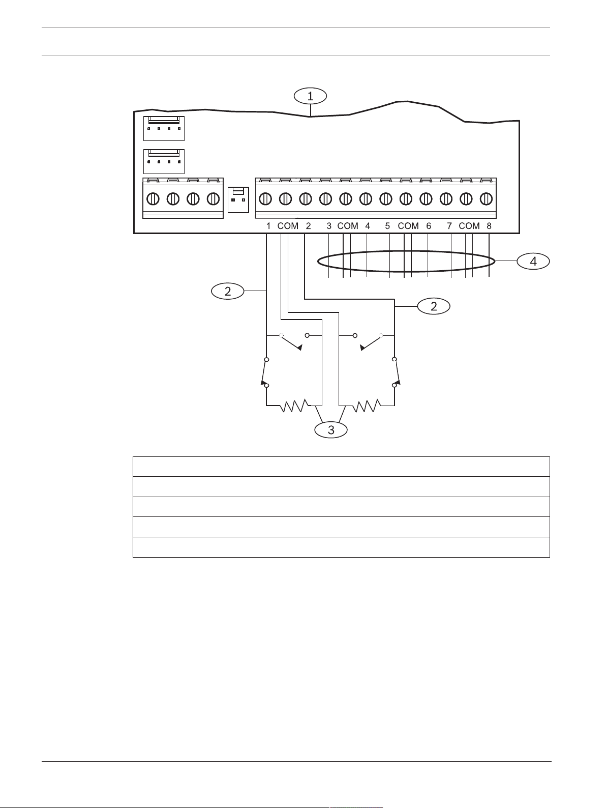
60 en | Off-board points Control Panels
Single EOL resistor circuit style
Figure13.2: B208 sensor loop wiring
Callout ᅳ Description
1 ᅳ Module
2 ᅳ Sensor loop
3 ᅳ EOL Resistor – 1.0 kΩ (2.0 kΩ and No EOL optional)
4 ᅳ Wiring to additional sensor loops
2017.04 | 15 | F.01U.287.180 Installation Manual Bosch Security Systems, Inc.
Page 61

Control Panels Off-board points | en 61
Point
COM
NC
1
4
3
2
Dual EOL resistor circuit style
Notice!
For the dual EOL resistor circuit style order ICP-1K22AWG-10, package of 10 1.0 kΩ EOL
resistors.
Figure13.3: Input wiring with dual EOL resistors
Callout - Description
1 - Point sensor loop terminals
2 - Normally closed device (contact)
3 - 1.0 kΩ resistor at device
4 - 1.0 kΩ resistor at EOL (end-of-line)
13.2 Test off-board points
Use the Service Walk Test to ensure that all off-board points operate properly.
Notice!
Walk test does not show extra points.
Setting the address switches on off-board point modules can create missing and extra points.
If the address switches on two or more modules are set to the same address, the points
associated with that address will not test correctly.
13.3 Extra Point events
The control panel generates Extra Point events when it detects a fault for an assigned point
with its Point Index set to 0 (disabled).
A wired point is considered assigned when its Point Source is set to Octo-input (SDI2).
An SDI2 Wireless point is considered assigned when its Point Source is Wireless and it has an
RFID assigned.
On-board points cannot produce Extra Point events. Points that are Service Bypassed cannot
produce Extra Point events.
13.4 Missing point conditions
The control panels respond to missing point conditions based on the point programming and
the turned on (armed) state of the point’s area. For example, if an interior motion detector
point is missing during a turned off (disarmed) state, the control panel generates a Missing
Trouble event; however, if the point is missing while the area is turned on (armed) the control
panel generates a Missing Alarm event. Non-fire, 24-hour points always generate a Missing
Alarm event, whereas Fire points always generate a Missing Fire Trouble event.
Bosch Security Systems, Inc. Installation Manual 2017.04 | 15 | F.01U.287.180
Page 62

62 en | Wireless modules Control Panels
!
14 Wireless modules
The control panel supports one B810 or one B820 for wireless sensors for easy and flexible
installation.
14.1 B810 receiver
The B810 is a wireless receiver that supports the full line of RADION wireless devices and the
RADION repeater. The receiver supports up to 504 wireless point devices, up to 1000 keyfobs,
and up to 8 repeaters.
Connect a RADION receiver SD to the SDI2 bus on the control panel using SDI2 terminals. This
section includes basic installation instructions. Refer to the RADION receiver SD (B810)
Installation Guide for detailed installation instructions.
14.1.1 SDI2 address settings
Notice!
The module reads the address switch setting only during module power up. If you change the
setting after you apply power to the module, you must cycle the power to the module in order
for the new setting to take effect.
The control panel supports only address 1.
14.1.2 Supervision
The control panel enables supervision of the module when you enroll at least one RF device.
Available RF devices on the control panel include RF Repeaters, wireless points, or user
keyfobs. Any failure to receive an expected response from an SDI2 module results in a system
fault display on all keypads and a fault event sent to the central station.
14.1.3 Installation and control panel wiring (B810)
Ensure that there is enough power for the module and other powered devices you want
connected to the system.
Refer to On-board outputs, page 50.
Caution!
Remove all power (AC and battery) before making any connections. Failure to do so might
result in personal injury and/or equipment damage.
Install the module
For best receiver reception results, place the receiver in a central location among the
transmitters.
1. Open the module.
2. Set the module to address 1 using the address switch.
3. Use the provided anchors and screws to mount the module base on the wall.
4. Pull the necessary wiring through the mounting plate. Refer to Wire to the control panel
(B810).
5. Install the module on the base.
Notice!
Mount the receiver in a location removed from metal. Metal objects (duct work, wire mesh
screens, boxes) reduce RF range.
2017.04 | 15 | F.01U.287.180 Installation Manual Bosch Security Systems, Inc.
Page 63

Control Panels Wireless modules | en 63
1
2
3
R
Y
G
B
7 COM 8
C
OUTPUT
B
1 k End of Line Resistors
Voltage Ranges
ON-BOARD POINTS
3.7 - 5.0 VDC
2.0 - 3.0 VDC
0.0 - 1.3 VDC
Open
Normal
Short
3 COM 4 5 COM 61 COM 2
R Y G B
SDI2
Device Bus
AUX
- 12 V +
TMPR
1 COM 2 7 COM 83 COM 4 5 COM 6
RESET
COM AUX
R Y G B
PWR A B COM
B C
OUTPUT
When wiring a module to a control panel, use the terminal strip labeled with R, Y, G, and B to
wire to the SDI2 terminals on the control panel. Wire the module in within the distances rated
for the module: 600 ft. (183 m) with 22 AWG (0.65 mm) wire or 1000 ft. (305 m) with 18 AWG
(1.02 mm) wire.
Figure14.1: B810 control panel wiring
Callout ᅳ Description
1 ᅳ Control panel
2 ᅳ Module
3 ᅳ Terminal strip wiring
14.2 B820 SDI2 Inovonics Interface Module
The B820 allow a control panel to interface with an Inovonics EN4200 EchoStream Serial
Receiver.
This section includes basic installation instructions. Refer to the SDI2 Inovonics Interface
Module (B820) Installation Guide for detailed installation instructions.
14.2.1 SDI2 address settings
Notice!
The module reads the address switch setting only during module power up. If you change the
setting after you apply power to the module, you must cycle the power to the module in order
for the new setting to take effect.
The control panel supports only address 1.
14.2.2 Supervision
The control panel enables supervision of the module when you enroll at least one RF device.
Available RF devices on the control panel include RF Repeaters, wireless points, or user
keyfobs. Any failure to receive an expected response from an SDI2 module results in a system
fault display on all keypads and a fault event sent to the central station.
14.2.3 Installation and control panel wiring (B820)
Ensure that there is enough power for the module and other powered devices you want
connected to the system.
Refer to On-board outputs, page 50.
Bosch Security Systems, Inc. Installation Manual 2017.04 | 15 | F.01U.287.180
Page 64

64 en | Wireless modules Control Panels
!
PWR A B COM
1
2
3
R
Y
G
B
7 COM 8
C
OUTPUT
B
1 k End of Line Resistors
Voltage Ranges
ON-BOARD POINTS
3.7 - 5.0 VDC
2.0 - 3.0 VDC
0.0 - 1.3 VDC
Open
Normal
Short
3 COM 4 5 COM 61 COM 2
R Y G B
SDI2
Device Bus
AUX
- 12 V +
TMPR
1 COM 2 7 COM 83 COM 4 5 COM 6
RESET
COM AUX
R Y G B
PWR A B COM
B C
OUTPUT
Caution!
Remove all power (AC and battery) before making any connections. Failure to do so might
result in personal injury and/or equipment damage.
Install the module
1. Set the module address using the address switch before you install it in the EN4200
housing.
2. Use a slotted screwdriver top press the housing release tabs and open the housing.
Remove the backing from the Velcro piece found in the product packaging to reveal the
Velcro adhesive. Place the Velcro’s adhesive side onto the back of the module. Remove
the remaining backing to use to secure the module in the housing.
3. Insert the module into the house, connect the serial ports on the B820 and EN4200, and
then press gently.
4. Refer to the EN4200 EchoStream Serial Receiver Installation Instructions for mounting and
wiring instructions for the receiver.
Wire to the control panel
When wiring a module to a control panel, use the terminal strip labeled with PWR, A, B, and
COM to wire to the SDI2 terminals labeled on the control panel. For terminal wiring, use 18
AWG to 22 AWG (1.02 mm to 0.65 mm) wire. Do not exceed a wire length of 1000 ft (300 m)
from the control panel.
Route the cabling through the control panel enclosure, and through the EN4200 housing.
Figure14.2: B820 to control panel wiring (B5512 shown)
Callout ᅳ Description
1 ᅳ Control panel
2 ᅳ Module
3 ᅳ Terminal strip wiring
2017.04 | 15 | F.01U.287.180 Installation Manual Bosch Security Systems, Inc.
Page 65

Control Panels Access control | en 65
!
15 Access control
The B6512 supports access control using the B901 Access Control Module. The B6512
supports up to 4 access doors.
Any of the following can grant access:
– Wiegand-style access control device (card reader) connected to the access control
module
– Request to enter (RTE) or request to exit (REX) input
– Unlock command on an SDI2 keypad (excluding fire keypads)
The control panel access control features can deny access when the system in On (armed).
The control panel can also grant access only to certain authorized users depending on
whether the area is all on, part on, or off. Programming for automatic disarming when
designated authorized users are granted access is also possible.
The Dual Authentication feature can optionally require passcode entry with presentation of
door credentials before access authorization is granted.
15.1 B901
The B901 Access Control Interface Module is a fully supervised, addressable SDI/SDI2 bus
device that allows access control integration for Bosch compatible control panels. This
module offers 14 programmable levels of access authority. Authority for access is controlled
by the user level, the group of the user, the time of day, the door state, and the area armed
state. Control each authority restriction through automatic and manual functions.
The module connects to a B6512 SDI2 bus or using the interconnect wiring connector. You
can connect more than one module to the control panel by wiring them in parallel. This
section includes basic installation instructions. For detailed installation instructions, refer to
the Access Control Module (B901) Installation and Operation Guide.
15.1.1 Address settings
Notice!
The module reads the address switch setting only during module power up. If you change the
setting after you apply power to the module, you must cycle the power to the module in order
for the new setting to take effect.
If multiple access control modules reside on the same system, each access control module
must have a unique address.
For valid addresses, refer to B901 address settings, page 129.
15.1.2 Supervision
With any failure to receive an expected response from the module, all keypads show a system
fault. The control panel sends a module trouble report to the central station (if configured for
module trouble reports).
15.1.3 Installation and control panel wiring (B901)
Ensure that there is enough power for the module and other powered devices you want
connected to the system.
Refer to On-board outputs, page 50.
Caution!
Remove all power (AC and battery) before making any connections. Failure to do so might
result in personal injury and/or equipment damage.
Bosch Security Systems, Inc. Installation Manual 2017.04 | 15 | F.01U.287.180
Page 66

66 en | Access control Control Panels
Install the module
1. Set the module address using the address switches before you install it in the enclosure.
2. Install the module in the enclosure with the control panel or in an adjacent enclosure that
is within the distances rated for the module: 1000 ft (305 m) with 18 AWG to 22 AWG
(1.02 mm to 0.65 mm) wire.
3. Use the screws provided with the module to secure the module in the enclosure.
Wire to the control panel
When you wire an SDI2 module to a control panel, you can use either the terminal strip
labeled with PWR, A, B, and COM to wire to corresponding SDI2 terminals labeled on the
control panel, or you can use the interconnect wiring connector and the included interconnect
cable.
For terminal wiring, use 18 AWG to 22 AWG (1.02 mm to 0.65 mm) wire.
Notice!
Use either the terminal strip wiring or interconnect wiring to the control panel. Do not use
both. When connecting multiple modules, you can combine terminal strip and interconnect
wiring connectors in series.
The B901 module also connects to the SDIx bus and functions as a D9210C when SDIx is
configured as SDI. Use either the terminal strip wiring or interconnect wiring to the control
panel.
15.2 Card reader wiring
To wire the access control module to a card reader, refer to the card reader instructions
printed on or shipped with the reader.
2017.04 | 15 | F.01U.287.180 Installation Manual Bosch Security Systems, Inc.
Page 67

Control Panels Program and test the control panel | en 67
16 Program and test the control panel
When you complete the hardware installation, reconnect the battery, and then plug in the
transformer. Next, program the control panel, and then test the control panel and
configuration.
Notice!
After system installation and any control panel programming, perform a complete system test.
A complete system test includes testing the control panel, all devices, and communication
destinations for proper operation.
16.1 Program the control panel
Use RPS or a keypad to program the control panel. Refer to RPS Help and Keypad Installer
menu, page 94.
16.2 Perform walk tests
When you perform a walk test, the control panel includes only points assigned to areas within
the keypad’s scope, based on the walk test type chosen. During a walk test, the points do not
process normally, and only indicate that they were tested. You can perform four different
types of walk tests on this system.
Each walk test type automatically terminates after 20 min of inactivity.
All point verification is disabled for all points during any walk test.
The control panel sends Walk Test Start and Walk Test End reports to the central station.
16.2.1 Fire walk test
A fire walk test allows you to test all visible, 24-hr points.
A fire walk test includes multiple point types. Points must meet the following criteria:
– Have a point source other than Unassigned
– Have a point index not set to Disabled (must be non-zero)
– Are not service bypassed
– Are not invisible points
– Have a point type of Keyswitch maintained, Keyswitch momentary, Open/Close Point,
Fire, Aux AC Supervision, or Gas
Performing a fire walk test:
1. Choose a keypad to conduct the test. Ensure that all areas are off (disarmed).
2. Open Main Menu and then go to the [3] Actions Menu > [3] Test > [1] Walk Test > [1]
Fire.
3. The keypad shows the number of points that remain untested.
4. To view the list of points, press Enter or View untested points. To scroll through the list
of points, use /Previous or /Next.
5. When you fault a point (press the test button on a smoke detector for example), the
keypad emits a brief tone and shows the point name.
Notice!
If the point loop has multiple detectors, then the keypad will emit a tone as confirmation for
each fault detected.
16.2.2 Intrusion walk test
An intrusion walk test includes points meeting the following criteria:
Bosch Security Systems, Inc. Installation Manual 2017.04 | 15 | F.01U.287.180
Page 68

68 en | Program and test the control panel Control Panels
– Have a point source other than Unassigned
– Have a point index not set to Disabled (must be non-zero)
– Point type must be for a Controlled Point; Part-On, Interior, or Interior Follower
– Are not service bypassed
– Are not invisible points
A controlled point can be programmed for trouble when disarmed.
Performing an intrusion walk test:
1. Choose a keypad to conduct the test. Ensure that all areas are off (disarmed).
2. Open Main Menu and then go to the [3] Actions Menu > [3] Test > [1] Walk Test > [1]
Intrusion.
3. The keypad shows the number of points that remain untested.
4. To view the list of points, press Enter or View untested points. To scroll through the list
of points, use /Previous or /Next.
5. When you fault a point (open a door for example), the keypad emits a brief tone and
shows the point name and that it has been tested (for example, Pt-4: P4 Follow Tested).
16.2.3 Service walk test
A service walk test allows you to walk test points assigned to any point type. The area scope
of the keypad that initiates the walk test determines which points are included in the test. All
points are included when the keypad scope is panel wide, including those with a Point Index
of 0.
A service walk test includes points:
– with a point source other than Unassigned
– that are disabled (Point Index set to 0) in addition to those that are enabled (non-zero
Point Index)
– that you have service bypassed
During a service walk test:
– The summary alarm and summary fire remain off, because there are no Fire or Burg alarm
conditions to summarize.
– The test does not generate any Extra Point troubles.
– The test does not log any Extra Point events.
Performing a service walk test:
1. Choose a keypad to conduct the test. Ensure that all areas are off (disarmed).
2. Open Main Menu and then go to the [3] Actions Menu > [3] Test > [1] Walk Test > [1]
Service.
3. The keypad shows the number of points that remain untested.
4. To view the list of points, press Enter or View untested points. To scroll through the list
of points, use /Previous or /Next.
5. When you fault a point (move in front of a motion sensor for example), the keypad emits a
brief tone and shows the point name and information (for example, Area-1 Point-7
Onboard: Short).
16.2.4 Invisible walk test
An invisible walk test allows you to test both controlled points and 24-hr points. Points
assigned to Point Indexes with the Invisible Point parameter set to Yes.
An invisible walk test includes points meeting the following criteria:
– Have a point source other than Unassigned
2017.04 | 15 | F.01U.287.180 Installation Manual Bosch Security Systems, Inc.
Page 69

Control Panels Program and test the control panel | en 69
– Have a point index not set to Disabled (must be non-zero)
– Have a point index configured with the point type of 24-Hour, Part On, Interior, or Interior
Follower
– Are not service bypassed
Performing an invisible walk test:
1. Choose a keypad to conduct the test. Ensure that all areas are off (disarmed).
2. Enter your passcode and press Enter. The keypad shows the number of points that
remain to be tested.
3. The keypad shows the number of points that remain untested.
4. To view the list of points, press Enter or View untested points. To scroll through the list
of points, use /Previous or /Next.
5. When you fault a point (open a door for example), the keypad emits a brief tone and
shows the name.
Bosch Security Systems, Inc. Installation Manual 2017.04 | 15 | F.01U.287.180
Page 70

70 en | Control panel board overview Control Panels
3
1
2
TMPR
1 COM 2 7 COM 83 COM 4 5 COM 6
RESET
ETHERNET
COM AUX
R Y G B
PWR A B COM
+ BAT -
18VAC
B C
OUTPUT
X
MODULE 1
Y
MODULE
RELEASE
NO C NC
OUTPUT A
7 COM 8
C
OUTPUT
B
USB
ETHERNET
100BASE-T
LINK
COMMUNICATION MODULE 1
1 k End of Line Resistors
Voltage Ranges
ON-BOARD POINTS
3.7 - 5.0 VDC
2.0 - 3.0 VDC
0.0 - 1.3 VDC
Open
Normal
Short
3 COM 4 5 COM 61 COM 2
R Y G B
SDI2
Device Bus
18 VAC
BATTERY OUTPUT A
AUX
- 12 V +
OUTPUT A
OUTPUT A
Jumper Under Cover
AUX PWR
COM
DRY
4
8
9
7
13
14
12
11
10
5 6
20 19
17
16 1518
17 Control panel board overview
Figure17.1: Control panel board overview (B5512 shown)
Callout ᅳ Description For more information, refer to:
1 ᅳ Jumper to configure OUTPUT A Configure OUTPUT A using the jumper, page 20
2 ᅳ OUTPUT A LED
3 ᅳ Holes to stabilize plug-in modules Installation and module wiring (B430), page 28 or
4 ᅳ Plug-in module connector
Installation and module wiring (B44x), page 34
5 ᅳ Green 100BASE-T LED On-board Ethernet diagnostic LEDs, page 33
6 ᅳ Yellow LINK LED
7 ᅳ Plug-in module retention clip Installation and module wiring (B430), page 28 or
8 ᅳ On-board Ethernet connector On-board Ethernet connection, page 32
9 ᅳ USB connector Programming
10 ᅳ Heartbeat LED (blue)
11 ᅳ RESET button
Installation and module wiring (B44x), page 34
12 ᅳ Terminals for Output B and Output C Open collector outputs, page 50
2017.04 | 15 | F.01U.287.180 Installation Manual Bosch Security Systems, Inc.
Page 71

Control Panels Control panel board overview | en 71
Callout ᅳ Description For more information, refer to:
13 ᅳ Tamper switch connector Install the enclosure and wiring label, page 18
14 ᅳ SDI2 interconnect wiring connector SDI2 interconnect wiring
15 ᅳ Sensor loop terminals for points 1 to 8 On-board points, page 54
16 ᅳ SDI2 terminals (power and data) SDI2 devices general system wiring, page 78
17 ᅳ Auxiliary power terminals On-board outputs, page 50
18 ᅳ Terminals for OUTPUT A Configure OUTPUT A using the jumper, page 20
19 ᅳ Battery terminals Secondary (DC) power, page 22
20 ᅳ 18 VAC power input terminals Primary (AC) power, page 22
Bosch Security Systems, Inc. Installation Manual 2017.04 | 15 | F.01U.287.180
Page 72

72 en | System wiring diagrams Control Panels
18 System wiring diagrams
18.1 System wiring overview
Notice!
For UL Certificated accounts, additional power can be obtained using only a UL Listed
auxiliary 12.0 VDC regulated, power-limited power supply, such as the B520.
All terminals are power limited except BAT+ (battery positive).
All terminals are supervised except OUTPUT A, OUTPUT B, and OUTPUT C.
For proper supervision, do not loop wire under terminals. Break the wire run to provide
supervision of connections.
2017.04 | 15 | F.01U.287.180 Installation Manual Bosch Security Systems, Inc.
Page 73

Control Panels System wiring diagrams | en 73
N/O 1
COMM
N/C 1
X1 +
X1 -
COMM
N/O 2
N/C 2
X2 +
X2 -
EOL
1
4
5
6
3
2
9
7
8
14
10
11
13
+
12
TMPR
1 COM 2 7 COM 83 COM 4 5 COM 6
RESET
ETHERNET
COM AUX
R Y G B
PWR A B COM
+ BAT -
18VAC
B C
OUTPUT
X
MODULE 1
Y
MODULE
RELEASE
NO C NC
OUTPUT A
7 COM 8
C
OUTPUT
B
USB
ETHERNET
100BASE-T
LINK
COMMUNICATION MODULE 1
1 k End of Line Resistors
Voltage Ranges
ON-BOARD POINTS
3.7 - 5.0 VDC
2.0 - 3.0 VDC
0.0 - 1.3 VDC
Open
Normal
Short
3 COM 4 5 COM 61 COM 2
R Y G B
SDI2
Device Bus
18 VAC
BATTERY OUTPUT A
AUX
- 12 V +
OUTPUT A
OUTPUT A
Jumper Under Cover
AUX PWR
COM
DRY
Figure18.1: System wiring overview (B5512 shown)
Callout ᅳ Description Callout ᅳ Description
1 ᅳ Control panel 8 ᅳ SDI2 wiring
2 ᅳ CX4010 UL Listed Class 2 Transformer 18 VAC
22 VA 60 Hz or in Canada, an ICP-TR1822-CA Plug-in
Transformer 120 VAC primary, 18 VAC 22 VA
secondary.
3 ᅳ To earth ground 10 ᅳ To ICP-EZTS Tamper Switch
4 ᅳ D122/D122L Dual Battery Harness, as required 11 ᅳ Programmable outputs
5 ᅳ Batteries (Unsupervised) 12 ᅳ External relay
6 ᅳ Audible signaling device 13 ᅳ USB connector
7 ᅳ UL Listed four-wire smoke detectors with EOL
9 ᅳ Supervised sensor loops, points 1 to 8 (Initiating
Device Circuits)
14 ᅳ RJ-45 modular jack for Ethernet (optional)
resistor
Bosch Security Systems, Inc. Installation Manual 2017.04 | 15 | F.01U.287.180
Page 74

74 en | System wiring diagrams Control Panels
1
BAT 2-
BAT 2+
BAT 1-
BAT 1+
CHGR-
VAUX+
SUPV
CHGR+
2
4
3
TMPR
1 COM 2 7 COM 83 COM 4 5 COM 6
RESET
ETHERNET
COM AUX R Y G B
PWR A B COM
+ BAT -18VAC
B C
OUTPUT
NO C NC
OUTPUT A
7 COM 8
C
OUTPUT
B
USB
ETHERNET
100BASE-T
LINK
COMMUNICATION MODULE 1
1 k End of Line Resistors
Voltage Ranges
ON-BOARD POINTS
3.7 - 5.0 VDC
2.0 - 3.0 VDC
0.0 - 1.3 VDC
Open
Normal
Short
3 COM 4 5 COM 61 COM 2
R Y G B
SDI2
Device Bus
18 VAC
BATTERY OUTPUT A
AUX
- 12 V +
OUTPUT A
OUTPUT A
Jumper Under Cover
AUX PWR
COM
DRY
18.2 Battery lead supervision wiring
Figure18.2: Battery lead supervision wiring (B5512 shown)
Callout ᅳ Description
1 ᅳ D113 Battery Lead Supervision Module, if required
2 ᅳ Batteries
3 ᅳ To supervision point
4 ᅳ Control panel
2017.04 | 15 | F.01U.287.180 Installation Manual Bosch Security Systems, Inc.
Page 75

Control Panels System wiring diagrams | en 75
o
SMOKE
RESET
SMOKE
B PWR
PASS-THRU
A COM
A COM B
1
2
3
5
4
6
18.3 2-wire smoke wiring (B201)
Figure18.3: B201 to control panel wiring
Callout ᅳ Description
1 ᅳ Control panel
2 ᅳ Interconnect wiring cable
3 ᅳ B201
4 ᅳ EOL resistor
5 ᅳ 1.8 kΩ EOL resistor (P/N: F01U009011) (included with the module)
6 ᅳ Smoke reset wire
Bosch Security Systems, Inc. Installation Manual 2017.04 | 15 | F.01U.287.180
Page 76

76 en | System wiring diagrams Control Panels
CCD 0x
-
0xxxx -
000
© RADIONICS INC.
D125B
1992
1
SWITCH
POWER
10
EARTH
GND
2
ZONE
B
4 5
PANEL
COMMON
3
ZONE
A
6
B-
LOOP
7
A-
LOOP
8
B+
LOOP
9
A+
LOOP
R21
R9
R10
R14
R11
R12
R22
RV2
RV3
RV4
R8
RV1
TB1/J1
R3C1R7
C3
C2
R13R4R5
R6
U1
PTC2
PTC1
R1
R2
D125B
1
2
3
4, 5
7, 9
6, 8
or
5
UX PWR
11
10
10
18.4 2-wire smoke wiring (D125B)
Figure18.4: D125B to control panel wiring (B5512 shown)
Callout ᅳ Description Callout ᅳ Description
1 ᅳ Switched auxiliary power from the control panel’s
Output A (NC)
1
2 ᅳ Connection from an on-board point on the control
7 ᅳ Supervised smoke detector to A LOOP negative
8 ᅳ Supervised smoke detector to B LOOP positive
panel to Zone B
3 ᅳ Connection from an on-board point on the control
9 ᅳ Supervised smoke detector to A LOOP positive
panel to Zone A
4/5 ᅳ Connection to the control panel’s common (one
10 ᅳ Earth ground
connection only)
6 ᅳ Supervised smoke detector to B LOOP negative 11 ᅳ Output A jumper (under cover) set to AUX PWR
1
You can also use Output B or C in conjunction with a D133 or D134 relay module.
18.5 Notification appliance circuit wiring
The control panel does not have an onboard NAC. Use a D192G Notification Appliance Circuit
Module for systems requiring a NAC.
Programming determines the output format and the conditions that activate the output. One
self-resetting circuit breaker protects against shorts. When using the output to activate
notification appliance circuits in UL Listed fire alarm applications, install a D192G Notification
Appliance Circuit module.
Refer to the D192G Notification Appliance Circuit Module Installation Guide (P/N: 4998122260)
for detailed wiring information and specifications.
2017.04 | 15 | F.01U.287.180 Installation Manual Bosch Security Systems, Inc.
Page 77

Control Panels System wiring diagrams | en 77
Figure18.5: Notification appliance circuit wiring (B5512 shown)
Callout ᅳ Description
1 ᅳ Control panel
2 ᅳ Output jumper set to configure OUTPUT A terminal C for AUX POWER (jumper cover
removed)
3 ᅳ D192G Notification Appliance Circuit module
4 ᅳ 1k Ω EOL resistor (P/N: F01U033966)
Bosch Security Systems, Inc. Installation Manual 2017.04 | 15 | F.01U.287.180
Page 78

78 en | System wiring diagrams Control Panels
1 21
8
7
4
5
3
7 COM 8
C
OUTPUT
B
1 k End of Line Resistors
Voltage Ranges
ON-BOARD POINTS
3.7 - 5.0 VDC
2.0 - 3.0 VDC
0.0 - 1.3 VDC
Open
Normal
Short
3 COM 4 5 COM 61 COM 2
R Y G B
SDI2
Device Bus
AUX
- 12 V +
TMPR
1 COM 2 7 COM 83 COM 4 5 COM 6
RESET
COM AUX R Y G B
PWR A B COM
B C
OUTPUT
6
18.6 SDI2 devices general system wiring
Figure18.6: SDI2 devices system wiring (B5512 shown)
Callout ᅳ Description B6512
capacity
B5512/
B5512E
capacity
B4512/
B4512E
capacity
1 ᅳ B208 Octo-input Modules 9 4 2 0
2 ᅳ B308 Octo-output Modules 9 5 3 0
3 ᅳ B426 Conettix Ethernet Communication Modules 1 1 1 1
4 ᅳ B450 Conettix Plug-in Communicator Interfaces 1 1 1 1
5 ᅳ B520 Auxiliary Power Supply Modules 4 4 2 2
6 ᅳ B810 or B820 SDI2 Inovonics Interface Modules 1 1 1 1
7 ᅳ Compatible keypads 12 8 8 4
8 ᅳ B901 Access Control Modules 4 0 0 0
Notice!
The SDI2 power terminal (R/PWR) is power limited. The SDI2 terminals are supervised.
18.6.1 SDI2 bus wiring recommendations
Use the following SDI2 bus wiring recommendations for SDI2 installation. The control panel
and SDI2 modules use the SDI2 bus to communicate with one another.
B3512/
B3512E
capacity
2017.04 | 15 | F.01U.287.180 Installation Manual Bosch Security Systems, Inc.
Page 79

Control Panels System wiring diagrams | en 79
7 COM 8
C
OUTPUT
B
1 k End of Line Resistors
Voltage Ranges
ON-BOARD POINTS
3.7 - 5.0 VDC
2.0 - 3.0 VDC
0.0 - 1.3 VDC
Open
Normal
Short
3 COM 4 5 COM 61 COM 2
R Y G B
SDI2
Device Bus
AUX
- 12 V +
TMPR
1 COM 2 7 COM 83 COM 4 5 COM 6
RESET
COM AUX R Y G B
PWR A B COM
B C
OUTPUT
You can wire modules via home run, daisy chain, or single level T-tap anywhere on the SDI2
bus.
Figure18.7: SDI2 bus wiring recommendations (B5512 shown)
Callout ᅳ Description
1 ᅳ Control panel
2 ᅳ SDI2 device (module or keypad)
3 ᅳ Daisy chain wiring
4 ᅳ Single-level T-tapped wiring
5 ᅳ Home run wiring
Bosch Security Systems, Inc. Installation Manual 2017.04 | 15 | F.01U.287.180
Page 80

80 en | System wiring diagrams Control Panels
Notice!
There can only be a difference of 2 volts (maximum) between the AUX power terminals of the
control panel or power supply and the device for the modules and keypads to work properly
under all conditions.
Maximum cable lengths
Follow these rules when wiring the SDI2 bus:
– The SDI2 bus requires the use of unshielded cable from 12 AWG to 22 AWG.
– Refer to the SDI2 device or keypad documentation for the allowable maximum distance
from the control panel.
– Maximum overall cable lengths are listed in the following table:
Cable capacitance Overall cable length Cable capacitance Overall cable length
pF/ft ft pF/ft ft
< 17 7500 27 5185
18 7500 28 5000
19 7350 29 4828
20 7000 30 4700
21 6666 31 4516
22 6363 32 4400
23 6086 33 4242
24 5800 34 4100
25 5600 35 4000
26 5385 36 3800
Table18.11: Maximum cable length
Notice!
Use unshielded cable only.
Maximum capacitance of 140nF (140,000 pF) per system. Contact the wire manufacturer for
the capacitance ratings of the wire being used.
2017.04 | 15 | F.01U.287.180 Installation Manual Bosch Security Systems, Inc.
Page 81

Control Panels System wiring diagrams | en 81
This equipment should be installed in a ccordance with the NFPA 70 (Na tional Electrical Code), the NFPA 72
(National F ire Alarm Code), and the local authority having j urisdiction. Depending on the application, the inst allation
is to be in acc ordance with one or more of the following UL standards:
UL681 Install ation and Classification of Mercantile and Bank Bu rglar Alarm Systems;
UL1076 Propriet ary Burglar Alarm Systems and Units; UL1641 Install ation and
Classificati on of Residential Burglar Alarm Systems. Printed informat ion describing proper inst allation,
operation, test ing, maintenance, repair ser vice and response to an alarm is to be provided with t his equipment.
Warning: Owner's Instruction Notice (P/N: F01U287181): Not to be removed by anyone except occupant.
Avertissement : guide de l'utilisateur (réf. : F01U287181) : seul l'occupant est autorisé à le retirer.
B6512/B5512/B4512/B3512
Bosch Security Systems, Inc. recommends testing the entire system
at least once a week, and having a qualified technician check
the system at a minimum of once every 3 years.
Suitable for the following applications: 1) Household Burglar Alarm System Units. 2) Household Fire Warning System Units. 3) Police Station connect, Mercantile Premise alarm system,
Mercantile Safe and Vault alarm system. For all Police Station applications, Model D8108A Attack Resistant Enclosure with a UL Listed local sounding device
is required. 4) Local, Mercantile Premise alarm system and Mercantile Safe and Vault alarm system. 5) Central Station, suitable as a dual signal line transmission system.
6) Proprietary Burg. 7) Holdup Alarm Units and System.
This equipment has been type tested and found to comply with the specifications in Part 15 of FCC rules for Class B Computing Devices. Operation is subject to the two following
conditions (1) this device may not cause any interference, and (2) this device must accept any interference received including interference that may cause undesired operation.
POWER SUPPLY REQUIREMENTS
The Power Supply provides a maximum of 800 mA for the Control Panel
and all Accessory Devices.
All external connections are inherently power limited, Class 2.
Requirements for battery standby time might reduce allowable output.
THIS UNIT INCLUDES AN ALARM VERIFICATION FEATURE THAT WILL RESULT IN A DELAY OF THE SYSTEM ALARM SIGNAL FROM THE INDICATED CIRCUITS.
THE TOTAL DELAY (CONTROL PANEL PLUS SMOKE DETECTORS) SHALL NOT EXCEED 60 SECONDS.
NO OTHER SMOKE DETECTOR SHALL BE CONNECTED TO THESE CIRCUITS UNLESS APPROVED BY THE LOCAL AUTHORITY HAVING JURISDICTION.
WARNING
Circuit (point)
Control panel
delay, seconds
Smoke detector
∗
Include detector data or the following or equivalent statement: “Use the delay (power-up/start-up) time marked
on the installation wiring diagram of the smoke detector or on the installed smoke detector(s).”
Model
Delay, seconds
This equipment should be installed in accordance with the
CSA C22.1, Canadian Electrical Code, Part 1, Safety Standard
for Electrical Installations.
B6512_B5512_B4512_B3512_ULLD-05
Communication:
Standard Line Security: Cellular or IP
A4: Cellular or IP
P3: DACT
CAUTION! AVERTISSMENT!
Avoid damage to Panel.
Do not connect 24 V to terminals.
Pout éviter d’emdommager la centrale :
Ne pas raccorder l’alimentation électrique
de volts aux bornes.
Minimum system requirements for Classification in accordance with ANSI/SIA CP-01-2010
UL Listed and Classified control unit Model B5512, B4512 or B3512;
UL Listed and Classified keypad Model B915/B915I, B920, B921C, B930, B942, or B942W
UL Listed Local Bell
Model number B430 complies with Part 68, FCC Rules. FCC Registration Number: ESVAL00BB430 Ringer Eq 0.0B
Model number B430 complies with CS-03, IC Rules, IC: 1249A-B430
REN 0.0
Optional B440/B441/B442/B443 - Or - Optional B430
GND OUT
Interconnect Connector
P1
P1
P1
OUTPUT A (C terminal) = AUX PWR
GND OUT
OUTPUT A (C terminal) = COM
OUTPUT A (C terminal) = dry contact
GND OUT
P1
BATTERY POSITIVE ONLY
BATTERY NEGATIVE ONLY
Do not connect to a
receptacle controlled by
a switch. Do not share
with other equipment.
B6512/B5512/B4512/B3512
use a CX4010 UL Listed
Class 2 Transformer
18 VAC 22 VA 60 HZ,
or in Canada, an
ICP-TR1822-CAN
Plug-in Transformer
120 VAC primary,
18 VAC 22 VA secondary.
Incorrect wiring
might damage
this equipment.
Maximum charging current is 1 A auxiliary power at 12 VDC.
BATTERY: Replace every 3 to 5 years with one or two
D126 or one D1218 12 V Lead Acid Batteries for Burglary or
Combination Fire and Burglary Systems.
WARNING! ATTENTION!
Multi-Battery installation requires Model D122
or D122L Dual Battery Harness.
Improper installation can be a fire hazard.
Le installations à plusieurs batteries nécessitent un
faisceau de câbles de Batterie double de modèle
D122 ou D122L. Toute installation inadéquate peut
causer un risque d’incedie.
For UL Listed fire alarm
applications, use a
D192G Notification
Appliance Circuit module.
SDI2 keypads,
input and
output modules,
communicators,
wireless
receivers, and
door controllers.
Supervised Loops
Open 3.7 to 5.0 VDC
Normal 2.0 to 3.0 VDC
Short 0.0 to 1.3 VDC
With 1 k
Ω
EOL Resistor (P/N:15093130-004). For
other EOL options, refer to the UL Installation Guide
(P/N: F01U287185).
Typical Initiating Devices are Door Contacts NO/NC,
Floor Mats, Motion Detectors, Glass Break
Detectors, etc.
EOL
D134 Dual
Relay Module
N/O 1
N/C 1
X1 +
X1 -
N/O 2
N/C 2
X2 +
X2 -
COMM 1
COMM 2
ICP-EZTS
Tamper
Switch
For a list of 2-wire smoke
detectors compatible with
the D125B Dual Class B
Initiating Module, refer to
the D125B Installation
Instructions
(P/N: F01U036340).
For a list of 2-wire smoke
detectors compatible with
the B201, refer to
the B201 Installation
Guide
(P/N: F01U296412).
GND OUT
An EOL power supervision module might be required
for use with 4-wire smoke detectors.
(Optional)
Auxilliary Powered Devices 11.5 to 12.4 VDC. Below 10.2 VDC,
the B6512/B5512/B4512/B3512 stops processing Loop inputs.
ATTENTION!
CETTE UNITÉ COMPREND UNE FONCTIONNALITÉ DE VÉRIFICATION DES ALARMES QUI CONDUIT À UN RETARD DU SIGNAL D'ALARME DU SYSTÈME PROVENANT DES CIRCUITS
INDIQUÉS. LA RETARD TOTAL (CENTRALE + DÉTECTEURS DE FUMÉE) NE DOIT PAS DÉPASSER 60 SECONDES. NE CONNECTER AUCUN AUTRE DÉTECTEUR DE FUMÉE À CES
CIRCUITS, SAUF SI CELA EST PERMIS PAR LES RÉGLEMENTATIONS LOCALES EN VIGUEUR
F01U287186-09a
For ULC installations, refer
to the ULC Installation
Guide
(P/N: F01U321698 for en
and for fr).
18.7 Wiring label
Bosch Security Systems, Inc. Installation Manual 2017.04 | 15 | F.01U.287.180
Page 82

82 en | Approved applications Control Panels
!
19 Approved applications
The UL System Chart references the components that are evaluated and listed by UL for
compatibility with B6512/B5512/B4512/B3512. These components meet the basic system
requirements for the applicable standard.
Refer to Compatible UL listed components, page 87.
The system wiring diagrams show the relationship between the control panel and the
accessory components.
Refer to System wiring diagrams, page 72.
19.1 Optional compatible equipment
You can use UL Listed components not requiring evaluation for electrical compatibility in many
applications when installed according to the manufacturer’s instructions.
19.1.1 Burglar applications
You can use UL Listed components not requiring evaluation for electrical compatibility in
burglary applications. In some cases, you must use a UL Listed interface module with the
sensors. Consult the individual component specification and installation documents to
determine suitability.
19.1.2 Bank safe and vault applications
You must use the D8108A Attack-Resistant Enclosure to meet UL Standard 681.
Refer to for wiring instructions and diagrams.
Control panel enclosure requirements
UL Standard 681 for Installation and Classification of Mercantile and Bank Burglary Alarm
Systems requires foil lining or equivalent protection of the control unit enclosure. The D8108A
Attack-Resistant Enclosure does not have a foil lining, but acceptable protection is provided by
mounting electronic vibration sensors inside the enclosure.
Notice!
Do not use proximity alarms (capacitance) to protect the control panel enclosure.
– Install the same electronic vibration sensors in the D8108A that are used to protect the
safe or vault.
– Mount the Sentrol 5402, Potter EVD-S, or Arrowhead S-3810 electronic vibration
detection (EVD) system inside the D8108A to meet the UL 681 requirements.
– Install and test the EVD sensor according to the manufacturer’s instructions.
– Mount the EVD sensor directly inside the metal cabinet of the D8108A.
Caution!
Do not install the EVD sensor within 6.4 mm (0.25 in) of the components or traces of the
printed circuit assembly.
Battery connections
– Using a D122 Dual Battery Harness, connect two 12 V 7 Ah batteries in the control panel
enclosure.
– Use a separate D8108A for the two 12 V 7 Ah batteries. When using a D122L Dual Battery
Harness, wire the batteries in parallel and connect the harness to the BAT+ and BAT-
terminals of the control panel.
2017.04 | 15 | F.01U.287.180 Installation Manual Bosch Security Systems, Inc.
Page 83

Control Panels Approved applications | en 83
0.64 mm (0.25 in)
minimum distance
+
-
+
-
2
1
1
14
9
7
5
6
8
3
4
10
11
13
12
9
16
15
11
Bell requirements
Use the following Rothenbuhler bell and balanced line modules with the control panel:
– UL Listed Model 5110 Bell
– UL Listed Model 4001-42 External Line Balancer
Wiring information for installations using the Rothenbuhler 5110/4001-42 High Security Bell
Refer to the following two figures for wiring information.
Figure19.1: Rothenbuhler 5110 4001-42 High Security Bell to control panel wiring
Callout ᅳ Description Callout ᅳ Description
1 ᅳ Self-contained UL listed vibration sensor 9 ᅳ D122/D122L Dual Battery Harness
2 ᅳ Control panel 10 ᅳ D126 Battery
3 ᅳ Accessory modules 11 ᅳ D8108A Enclosure
4 ᅳ High line security module 12 ᅳ Proximity/control unit
5 ᅳ 4001-42 Balanced Line Module 13 ᅳ Normally open (NO)
6 ᅳ 5110 Bell 14 ᅳ Normally closed (NC)
7 ᅳ D133 Relay 15 ᅳ End-of-line (EOL) resistor
8 ᅳ Alarm input point
1
Use Terminals 1 through 8. (Select only one.)
2
Use a D113 Battery Lead Supervision Module to supervise the battery connections
1
16 ᅳ Safe
2
.
Bosch Security Systems, Inc. Installation Manual 2017.04 | 15 | F.01U.287.180
Page 84

84 en | Approved applications Control Panels
R E D O R G W H T B L K
N/O 1
COMM 1
N/C
X1 -
X1+
2
1
4
3
2
1
1 632
COM AUX
P1
3
9
7
6
4
10
11
14
12
9
13
9
8
5
TMPR
1 COM 2 7 COM 83 COM 4 5 COM 6
RESET
ETHERNET
COM AUX
R Y G B
PWR A B COM
+ BAT -
18VAC
B C
OUTPUT
NO C NC
OUTPUT A
7 COM 8
C
OUTPUT
B
USB
ETHERNET
100BASE-T
LINK
COMMUNICATION MODULE 1
1 k End of Line Resistors
Voltage Ranges
ON-BOARD POINTS
3.7 - 5.0 VDC
2.0 - 3.0 VDC
0.0 - 1.3 VDC
Open
Normal
Short
3 COM 4 5 COM 61 COM 2
R Y G B
SDI2
Device Bus
18 VAC
OUTPUT A
AUX
- 12 V +
Figure19.2: Detailed Rothenbuhler 5110_4001-42 High Security Bell to control panel wiring (B5512 shown)
Callout ᅳ Description Callout ᅳ Description
1 ᅳ 5110 Logic Board 8 ᅳ Alarm input point*
2 ᅳ 4001-42 External Line Balancing Module 9 ᅳ 10 kΩ resistor
3 ᅳ Control panel set to OUTPUT A using AUX
PWR
4 ᅳ Alarm output 11 ᅳ D133 Relay Module
5 ᅳ Alternate alarm (use B or C) 12 ᅳ BBL In 4
10 ᅳ Optional silence switch
6 ᅳ Common 13 ᅳ BBL Out 5
7 ᅳ +12.0 VDC 14 ᅳ Terminal TB1
*
Use Terminals 1 through 8. (Select only one.)
Notice!
Bell Test at Arming: UL Standard 365 requires a Bell Test at arming for bank safe and vault
applications.
2017.04 | 15 | F.01U.287.180 Installation Manual Bosch Security Systems, Inc.
Page 85

Control Panels Approved applications | en 85
System configuration requirements
The following configuration and programming options are required for UL Bank Safe and Vault
Systems. Refer to RPS Help or the control panel’s Program Entry Guide for programming
information.
Safe and Vault protective circuits
To test the devices that protect the safe(s) or vault(s) without sounding the bell, specify the
devices’ points as controlled zones and supervised for trouble conditions. Refer to Point Index
in RPS Help or the control panel’s Program Entry Guide more information.
Bell configuration
– UL 365 requires a bell time of 15 to 30 min. The Rothenbuhler 5110 Bell provides
selectable bell time through manipulation of its jumpers. Refer to the manufacturer’s
installation instructions for more information.
– In addition to the jumper settings inside the bell, you can activate the control panel for a
bell time of 15 min.
– UL 365 requires a Bell Test at arming and you must enable it in control panel
programming.
– Refer to the various bell parameters in RPS Help or the control panel’s Program Entry
Guide for more bell time and test programming information.
Bell test
– To enable the bell test feature, you enable an unused area of the control panel. Enable
the bell test feature for the unused area only. Program OUTPUT B as the area bell output
for the unused area.
– Make all passcodes with authority to arm the safe or vault and also send a Closing Report
valid in this area. Program the area for a five-second exit delay.
– To complete the installation for this feature, connect the output to a D134 Dual Relay
Module.
Exit delay
Do not program the control panel’s maximum exit delay longer than 30 seconds.
19.1.3 Fire applications
You can use UL Listed fire initiating devices not requiring electrical compatibility evaluation in
any application. For example, the four-wire smoke detectors, heat detectors, waterflow
switches, and manual pull stations are suitable fire initiating devices. Consult the individual
component specification and installation documents to determine suitability.
Notice!
UL requires that the control panel supervises any device powered from a power output.
Notice!
The control panel does not support multiple detectors in alarm. The control panel is
compatible with detectors with optional features. Do not mix detectors from different
manufacturers on the same circuit.
Four-wire smoke detectors
When using four-wire smoke detectors, install a power supervision device according to the
manufacturer’s instructions. You can connect any number of four-wire smoke detectors to the
control panel (subject to available auxiliary power).
Bosch Security Systems, Inc. Installation Manual 2017.04 | 15 | F.01U.287.180
Page 86

86 en | Approved applications Control Panels
The Reset Sensor command is available from the keypads when the Reset Sensor is enabled.
Connect the smoke detectors to a suitable interface such as the B208 Octo-input Module or
on-board point to meet UL and NFPA requirements.
Notification Appliance Circuit (NAC)
Refer to Notification appliance circuit wiring, page 76.
Notice!
Test Weekly: Perform a Fire Test weekly.
Further information
–
– Household Fire Warning equipment, page 91
NFPA Style A (Class “B”) Circuit
Loops A and B on the D125B Module are NFPA Style A (Class “B”) initiating circuits suitable
for connecting any fire alarm initiating device, including two-wire and four-wire smoke
detectors.
Connecting initiating devices to on-board points (1 through 8) on the control panel.
– Use a D125B Powered Loop Interface Module with two-wire initiating devices.
– Use a D129 Dual Class “A” (NFPA Style D) Initiating Circuit Module with any type of
initiating device, except a two-wire smoke detector.
Connecting initiating devices to off-board points:
– Do not connect two-wire smoke detectors to POPITs or MUX bus inputs.
– Use the D9127U or D9127T POPIT Modules to connect four-wire smoke.
Other devices
Use a D130 Relay Module, D8129 OctoRelay, or Switched Aux (Terminal 8) to provide reset
capability to other initiating devices such as:
– B308 Octo-output Module
– D125B Powered Loop Interface Module (2-wire smoke detector module)
– D129 Dual “Class A” Initiation Circuit Module (4-wire smoke detector)
– D9127T/U POPITs
– On-board points
Install devices according to the manufacturer’s instructions. For more information, refer to Off-
board outputs, page 52.
For battery calculations, refer to Standby battery requirements and calculations, page 89.
Notice!
Test Weekly: Perform a Fire Test weekly. According to UL 864, a Fire Test tests both the AC
power and the battery.
19.1.4 Enclosures
Mount the control panel assembly in any of the Bosch Security Systems, Inc. enclosures listed:
– B10 Medium Control Panel Enclosure
– B11 Small Control Panel Enclosure
– D2203 Enclosure
– B8103 Universal Enclosure*/D8103 Universal Enclosure*
– D8109 Fire Enclosure (red)*
– D8108A Attack Resistant Enclosure*
2017.04 | 15 | F.01U.287.180 Installation Manual Bosch Security Systems, Inc.
Page 87

Control Panels Approved applications | en 87
*Requires a B12 mounting bracket.
B10, B11, D2203, and D8103 enclosures
The B10, B11, D2203, and D8103 enclosures are suitable for residential fire and burglary
installations and commercial burglary applications that do not require attack resistance or the
approval by Factory Mutual (FM) or New York City – Materials and Equipment Acceptance
(NYC-MEA). Refer to Compatible UL listed components, page 87 for acceptable applications.
D8108A Enclosure
The D8108A is attack resistant and intended primarily for UL commercial burglar alarm and
mercantile safe and vault applications requiring a local bell. Use this enclosure in any burglar
or fire alarm application where the D8109 Enclosure is suitable.
With some modification, you can use the D8108A for bank safe and vault applications. UL lists
the D8108A for all commercial fire alarm applications. It is approved by FM, CSFM, and the
NYC-MEA.
D8109 Red Fire Enclosure
Generally, the D8109 is used for fire alarm applications. It is approved by FM, CSFM, and the
NYC-MEA.
B12 Mounting Plate for D8103 Enclosure
The mounting plate is compatible with the D8103, D8108A, and D8109 Enclosures.
19.2 Combination fire and intrusion alarm systems
A system can include a combination of fire and intrusion devices on any bus or module.
19.3 Compatible UL listed components
Househol
d
Burglary
Minimum Hours of Standby
Battery
B10 Medium Control Panel
Enclosure
B11 Small Control Panel
Enclosure
B201 2-wire Powered Loop
Module
B208 Octo-input Module Opt. Opt. Opt. Opt. Opt. Opt. Opt.
4 24 + 4 min alarm 4 4 4 8
Opt. Opt. Opt. Opt. Opt. Opt. Opt.
Opt. Opt. Opt. Opt. Opt. Opt. Opt.
Opt. Opt. Opt. Opt. Opt. Opt. Opt.
Household
Fire
Household
Fire/ Burglary
Combined
Central
Station
Burglary/
Proprieta
ry
Police
Connecte
d
Burglary
Local
Burglary
Holdup
B308 Octo-output Module Opt. Opt. Opt. Opt. Opt. Opt. Opt.
B426 Conettix Ethernet
Communication Module
B430 Plug-in Telephone
Communicator
B440 Conettix Plug-in
Cellular Communicator
Bosch Security Systems, Inc. Installation Manual 2017.04 | 15 | F.01U.287.180
Opt. Opt. Opt. Opt. Opt. Opt. Opt.
Opt. Opt. Opt. Opt. Opt. Opt. Opt.
Opt. Opt. Opt. Opt. Opt. Opt. Opt.
Page 88

88 en | Approved applications Control Panels
B441 Conettix Plug-in
Opt. Opt. Opt. Opt. Opt. Opt. Opt.
Cellular Communicator
B442 Conettix Plug-in
Cellular Communicator
B443 Conettix Plug-in
Cellular Communicator
B450 Conettix Plug-in
2
2
Opt. Opt. Opt. Opt. Opt. Opt. Opt.
Opt. Opt. Opt. Opt. Opt. Opt. Opt.
Opt. Opt. Opt. Opt. Opt. Opt. Opt.
Communicator Interface
B520 Auxiliary Power Supply
Opt. Opt. Opt. Opt. Opt. Opt. Opt.
Module
B810 RADION receiver SD Opt. Opt. Opt. Opt. Opt. Opt. Opt.
B820 SDI2 Inovonics
Opt. Opt. Opt. Opt. Opt. Opt. Opt.
Interface Module
B901 Access Control
Module
3
Opt. Opt. Opt. Opt. Opt. Opt. Opt.
B915/B915I Basic Keypad 1+ 1+ 1+ 1+ 1+ 1+ Opt.
B920 Two-line Alphanumeric
1+ 1+ 1+ 1+ 1+ 1+ Opt.
Keypad (SDI2)
B921C Two-line Capacitive
1+ 1+ 1+ 1+ 1+ 1+ Opt.
Keypad
B930 keypads 1+ 1+ 1+ 1+ 1+ 1+ Opt.
B942/B942W Touch Screen
1+ 1+ 1+ 1+ 1+ 1+ Opt.
Keypad
CX4010 Plug-in Transformer
Required for all applications. Opt.
(18 VAC 22 VA 60 Hz)
D125B Dual Class B Initiating
Opt. Opt. Opt. Opt. Opt. Opt. Opt.
Module
D126 Standby Battery (12 V,
Opt. Opt. Opt. Opt. Opt. Opt. Opt.
7 Ah)
D130 Auxiliary Relay Module Opt. Opt. Opt. Opt. Opt. Opt. Opt.
D133 Single Relay Module Opt. Opt. Opt. Opt. Opt. Opt. Opt.
D134 Dual Relay Module Opt. Opt. Opt. Opt. Opt. Opt. Opt.
D1218 Battery (12 V, 18 Ah) Opt. Opt. Opt. Opt. Opt. Opt. Opt.
D192G Class “B”, Style Y
Opt. Req. Opt. Opt. Opt. Opt. Opt.
Bell Circuit Supervision
D8004 Transformer
Opt. Opt. Opt. Opt. Opt. Opt. Opt.
Enclosure
2017.04 | 15 | F.01U.287.180 Installation Manual Bosch Security Systems, Inc.
Page 89

Control Panels Approved applications | en 89
D8108A Attack Resistant
Opt. Opt. Opt. Opt. No Opt. Opt.
Enclosure or D8109 Fire
Enclosure
D8108A Attack Resistant
Enclosure
1
Opt. Opt. Opt. Opt. Opt. Opt. Opt.
Key
No
Req.
Opt .
1+
1
For commercial applications using the B430, and when doing local or police station connect applications, the
Not acceptable for this application.
Required for this application.
Optional for this application.
1 or more required for this application. Consult the appropriate standard.
D8108A Enclosure is required for all applications.
2
Check for availability in your region.
3
B6512 only.
19.4 Standby battery requirements and calculations
Standby battery calculations
UL 365 requires 72 hours of standby battery capacity. Limit the auxiliary power current for all
devices, including keypads, to 80 mA or less to meet this requirement.
A B C
Model Number Qty
Used
B6512/B5512/
______ 125 x 1 = 125 125 x 1 = 125 155 x 1 = 155
AC Power On Normal
Current (mA)
Each
Qty Total Each
Unit
AC Power Off Minimum
Current (mA)
Qty Total Each
Unit
In Alarm Maximum
Current (mA)
Qty Total
Unit
B4512/B3512
B201 ______ 18 x Qty = ______ 18 x Qty = ______ 35 x Qty = ______
B208 ______ 35 x Qty = ______ 35 x Qty = ______ 35 x Qty = ______
1
B308
______ 22 x Qty = ______ 22 x Qty = ______ 22 x Qty = ______
B426 ______ 100 x Qty = ______ 100 x Qty = ______ 100 x Qty = ______
B430 ______ 5 x 1 = ______ 5 x Qty = ______ 25 x 1 = ______
B440 ______ 35 x 1 = ______ 35 x 1 = 35 150 x 1 = ______
B441 ______ 35 x 1 = ______ 35 x 1 = 35 150 x 1 = ______
B442 ______ 35 x 1 = ______ 35 x 1 = 35 150 x 1 = ______
B443 ______ 35 x 1 = ______ 35 x 1 = 35 150 x 1 = ______
2
B450
______ 30 x Qty = ______ 30 x Qty = ______ 30 x Qty = ______
B520 ______ 15 x Qty = ______ 15 x Qty = ______ 15 x Qty = ______
B810 ______ 100 x Qty = ______ 100 x Qty = ______ 100 x Qty = ______
B820 ______ 100 x Qty = ______ 100 x Qty = ______ 110 x Qty = ______
Bosch Security Systems, Inc. Installation Manual 2017.04 | 15 | F.01U.287.180
Page 90

90 en | Approved applications Control Panels
B901 ______ 110 x Qty = ______ 100 x Qty = ______ 1106x Qty = ______
B915/B915I ______ 35 x Qty = ______ 35 x Qty = ______ 70 x Qty = ______
B920 ______ 35 x Qty = ______ 35 x Qty = ______ 70 x Qty = ______
B921C ______ 45 x Qty = ______ 45 x Qty = ______ 85 x Qty = ______
B930 ______ 35 x Qty = ______ 35 x Qty = ______ 80 x Qty = ______
B942/B942W
3
______ 200 x Qty = ______ 200 x Qty = ______ 300 x Qty = ______
D125B ______ 25 x Qty = ______ 25 x Qty = ______ 168 x Qty = ______
D127 ______ 5 x Qty = ______ 5 x Qty = ______ 55 x Qty = ______
D129 ______ 23 x Qty = ______ 23 x Qty = ______ 25 x Qty = ______
D132A ______ 10 x Qty = ______ 10 x Qty = ______ 70 x Qty = ______
4
D133
D134
5
______ x Qty = ______ x Qty = ______ x Qty = ______
______ x Qty = ______ x Qty = ______ x Qty = ______
D185 ______ 245 x Qty = ______ 245 x Qty = ______ 300 x Qty = ______
D192G ______ 35 x Qty = ______ 35 x Qty = ______ 100 x Qty = ______
Ratings of other devices in the system that are not shown above:
____ ______ _____ x Qty = ______ ______ x Qty = ______ ____ x Qty = ______
____ ______ _____ x Qty = ______ ______ x Qty = ______ ____ x Qty = ______
____ ______ _____ x Qty = ______ ______ x Qty = ______ ____ x Qty = ______
____ ______ _____ x Qty = ______ ______ x Qty = ______ ____ x Qty = ______
Total A = ______ Total B = ______ Total C = ______
1
The In Alarm calculation for the B308 is: 20 x Qty + (16.25 x number of relays).
2
Currents listed are for the B450 only. Include plug-in device currents in calculations.
3
If using the proximity reader, add 100 mA to columns A, B, and C before calculating.
4
38 mA for each active relay.
5
Value = Minutes of alarm operation/60.
6
Use 110 mA + reader. Do not exceed 260 mA.
Table19.12: Current rating chart for standby battery calculations
Total B
1
Hours Total C
1
Alarm Operation
2
Contingency Total Ah
3
( ________ x 24 ) + ( ________ x 0.083) + 15% = _________
1
Refer to previous table.
2
Value = Minutes of alarm operation/60
3
Total Ah requirements must not exceed the Ah capacity of batteries:
– One D126 Battery = 7 Ah
– Two D126 Batteries = 14 Ah
– One D1218 Battery = 18 Ah
Table19.13: General ampere-hour (Ah) calculation formula
2017.04 | 15 | F.01U.287.180 Installation Manual Bosch Security Systems, Inc.
Page 91

Control Panels Approved applications | en 91
Application Minimum Required
Minimum Alarm Time (min)
Standby Time (hr)
Residential Burglary 4 4
Proprietary Burglary 4 N/A
Central Station (Bank) 72 N/A
Central Station (Mercantile) 4 N/A
Police Station Connected (Bank) 72 30 (CUL)/15 (UL)
Police Station Connected (Mercantile) 24 30 (CUL)/15 (UL)
Local Burglary (Bank) 72 30 (CUL)/15 (UL)
Local Burglary (Mercantile) 24 30 (CUL)/15 (UL)
Holdup 8 N/A
Residential Fire 24 5 (CUL)/4 (UL)
Table19.14: Minimum standby and alarm times
Type Required capacity Calculations
Household Burglary and
4 h
Commercial Burglary
Bank Safe and Vault 72 h (UL 365). Auxiliary power current for all devices, including
keypads, must be limited to 80 mA or less to meet this
requirement.
Table19.15: Standby battery requirements
Notice!
Because of changing regulations, verify the necessary time with your local authority having
jurisdiction (AHJ).
19.4.1 Household Fire Warning equipment
The Household Fire Warning Equipment Standard requires 24 hours of standby current plus 4
minutes of alarm operation at the end of the 24-hour period. Use battery Ah calculations to
confirm compliance. The formula shown below includes the calculation for 4 minutes of alarm
operation at the end of the 24-hour period, and a 15% contingency factor that allows for
depletion of battery capacity with age.
1
Total B
Hours Total C
( ________ x 24 ) + ( ________ x 0.083) + 15% = _________
1
Refer to previous table.
2
Value = Minutes of alarm operation/60
3
Total Ah requirements must not exceed the Ah capacity of batteries:
– One D126 Battery = 7 Ah
– Two D126 Batteries = 14 Ah
– One D1218 Battery = 17.2 or 18 Ah
1
Alarm Operation
2
Contingency Total Ah
3
Table19.16: Household fire ampere-hour (Ah) calculation formula
Bosch Security Systems, Inc. Installation Manual 2017.04 | 15 | F.01U.287.180
Page 92

92 en | Approved applications Control Panels
19.5 UL 365 - Police Station Connected Burglar Alarm Units and Systems
In a mercantile burglar alarm system, a mercantile alarm sounding device located within a
building but outside the protected area is acceptable provided it is rated for outside service
and alarm conditions are transmitted to:
– The dispatch location of the law enforcement agency having jurisdiction over the
protected property
or
– A central station or residential monitoring station complying with the Standard for
Central-Station Alarm Services, UL 827.
In a mercantile burglar alarm system, an alarm sounding device located within the area of
greatest protection, or outside the area of greatest protection but within an area protected by
an alarm system, and that shares a common control unit with the system installed in the area
of greatest protection, is acceptable provided it is rated for inside service and alarm
conditions are transmitted to:
– The dispatch location of the law enforcement agency having jurisdiction over the
protected property
or
– A central station or residential monitoring station complying with the Standard for
Central-Station Alarm Services, UL 827.
Mount an inside sounding device at least 10 feet (3.05 m) above the floor or at the surface of
the ceiling. When fixed construction within the area could provide access for an intruder, the
mount the alarm sounding device at least 4 ft (1.2 m) as measured horizontally, away from the
edges of the fixed construction or at least 10 ft (3.05 m) above it so as to minimize access by
an intruder.
19.6 UL 636 - Holdup Alarm Units and System
When using the system for hold-up operation, a hold-up point should be assigned to a point as
follows:
– P## Point Type set to 24-hr, P## Point Response set to 0 (Point is constantly armed
regardless of the status of the system.)
– P## Invisible Point set to Yes (Keypads do not display alarm activity from this point.)
When using Modem Format communication type, the unique point text should be set to ‘‘HoldUp’’, or equivalent language per the AHJ.
When using Contact ID communication type, because the Contact ID system doesn’t provide
custom text, the hold-up point should be associated as a “hold-up” point at the receiving
station. Set Area # Delay Restorals as follows:
– Area # Delay Restorals = No (Restoral report is sent when point restores.)
19.7 Required values to achieve 180s (ULC)/200s (UL) supervision interval
Applicable for both IP and cellular communication.
Requirement Parameter
Supervision interval for IP and Cellular
communication is 200 seconds (UL)
Panel Wide Parameters > Enhanced Communications > Receiver
Supervision Time set to 200 seconds
2017.04 | 15 | F.01U.287.180 Installation Manual Bosch Security Systems, Inc.
Page 93

Control Panels Approved applications | en 93
Requirement Parameter
Supervision interval for IP and Cellular
communication is 180 seconds (ULC)
19.8 ULC
Conduct testing monthly, with the primary de-energized.
Panel Wide Parameters > Enhanced Communications > Receiver
Supervision Time set to Custom, Poll Rate set to 89, ACK Wait
Time set to 15, and Retry Count set to 5
Bosch Security Systems, Inc. Installation Manual 2017.04 | 15 | F.01U.287.180
Page 94

94 en | Keypad Installer menu Control Panels
20 Keypad Installer menu
In addition to using RPS to configure and diagnose a system, you can also perform
programming and diagnostics using a keypad. Programming and diagnostics options appear on
the keypad when you access the Main Menu (Installer) option, which includes the Installer
menu. The Main Menu (Installer) option becomes available during normal control panel
operation only when you enter your installer passcode and press Enter. The default installer
passcode is 1-2-3.
The tools within the Main Menu (Installer) are:
– Programming Menu. Program several parameters to make your system operational,
including phone number and format, enhanced communication options, RPS parameters,
users, points, and keypad parameters. Refer to [1] Program menu (Programming), page
100 for more detailed information on each programming option, and to RPS Help or the
control panel’s Program Entry Guide.
– Wireless Menu. Add, replace, remove, and diagnose points and repeaters. Refer to [2]
Wireless menu, page 119.
– Diagnostics Menu. Diagnose points, repeaters, cellular service, IP cameras, and Cloud.
Refer to [3] Diags menu, page 121.
– Service Bypass Menu. View whether points are removed from service. Refer to [4] Service
Bypass (Serv Byp) menu, page 123.
– Version Menu. View the version information for the control panel, encryption, and more.
Refer to [5] Versions menu, page 123.
– Cloud Menu. Enable Cloud connectivity for the control panel. Refer to [6] Cloud menu,
page 124.
Installer keypads and SERVICE MODE
The Installer menu is also available from the Service menu when in SERVICE MODE. The
Service menu is a subset of the Main menu (Installer) option. You can use Service mode at any
keypad, but the feature is most useful when you want to directly connect an Installer keypad
to the control panel for keypad programming at the control panel.
Entering SERVICE MODE:
1. Set the Installer keypad to address 0.
2. Connect it to the control panel.
3. Use the control panel RESET button to enter SERVICE MODE. The rate of flashing of the
Heartbeat LED increases while in SERVICE MODE.
2017.04 | 15 | F.01U.287.180 Installation Manual Bosch Security Systems, Inc.
Page 95

Control Panels Keypad Installer menu | en 95
7 COM 8
USB
ETHERNET
100BASE-T
LINK
1 k End of Line Resistors
Voltage Ranges
ON-BOARD POINTS
3.7 - 5.0 VDC
2.0 - 3.0 VDC
0.0 - 1.3 VDC
Open
Normal
Short
3 COM 4 5 COM 6
C
OUTPUT
B
TMPR
7 COM 83 COM 4 5 COM 6
RESET
ETHERNET
B C
OUTPUT
RESET
Figure20.1: RESET button and Heartbeat LED location (B5512 shown)
Accessing SERVICE MODE (rapid pulsing Heartbeat LED):
1. Press and hold the control panel RESET button until the Heartbeat LED flashes fast. The
keypad shows SERVICE MODE and prompts for the installer passcode.
2. Enter your installer passcode and press ENTER.
Exiting SERVICE MODE and returning to normal operation (slow pulsing Heartbeat LED):
Press and hold the control panel RESET button for approximately 5 seconds until the
Heartbeat LED turns off. The control panel resets.
Conventions for this section
This guide to the keypad Installer menu provides instructions for using the keypad, based on
the following conventions:
– All instructions access the Installer menu from the Main Menu (Installer) option, not
while in SERVICE MODE.
– This section covers all compatible keypads. It provides specific steps for each keypad
style, when applicable.
– For simplicity, the keypad Installer menu tree and instructions combine the two-line
keypad number selections with the text and graphic steps of other keypads. For example,
rather than indicating that the two-line keypad reads Press [2] for enhanced comm
parameters, and that a different keypad reads Enhanced Comm Parms, this section
indicates the selection as [2] Enhanced Comm Parms.
– Go to [1] Programming Menu > [1] Reporting > [2] Network > [2] Enhanced Comm
Parms.
Keypad menu trees
This section includes menu trees for the Installer menu structure, and the structures of the
B93x/B94x and B91x/B92x keypads user menus, for reference.
Bosch Security Systems, Inc. Installation Manual 2017.04 | 15 | F.01U.287.180
Page 96

RF point diag
Diags
menu
Wireless
menu
Installer
menu
Areas
RPS
Reporting
Network
Keypad
1
Users
1
2
3
5
6
4
2
Installer
passcode
3
4
Srvc Byp menu
5
ESC
Exit
Program
menu
1
Points
7
Disable
8
ESC Exit
Phone
Network
Routing
Notification
2
3
4
1
Enhanced Comm
Enhanced Comm Parms2
1
Exit Reporting menu
ESC
Format
AES Size
AES Entry
Exit
ESC
Phone Number
Format
Exit menu
ESC
ESC Exit
Primary
Backup
Exit menu
ESC
Ethernet
Cellular
2
1
ESC Exit
Module Parameters
Address Parameters2
1
ESC
RPS Passcode
RPS Phone Number
RPS IP Address
RPS Port Number
2
3
4
1
ESC Exit
State
Account #
Exit menu
ESC
Exit
ESC
Area
Name
Exit menu
ESC
RF Point Menu
RF Repeater Menu
2
3
1
ESC Exit
RF Diagnostic Menu
Enroll point RFID
Replace point RFID
2
3
1
ESC Exit
Remove point RFID
Add repeater
Replace repeater
ESC Exit
Remove repeater
1
RF repeater diag
2
1
Exit
ESC
RF point state
RF point signal2
1
Exit
ESC
RF repeater state
RF repeater signal2
Exit
ESC
Wireless
Network2
1
DNS Parameters
Scope
DHCP Enable
UPnP Enable
2
1
Exit menu
ESC
3
IP Address
Subnet Mask
2
1
Exit menu
ESC
Default Gateway
3
Port Number
4
IPv4 Server Address
IPv6 Server Address
2
1
Exit
ESC
Module Hostname
3
2
3
1
Versions menu
ESC
Cellular
IP Camera
4
3
Settings
Connection
2
1
Exit
ESC
SDI2 Cellular (1)
SDI2 Cellular (2)2
1
ESC
Bus Module (1)
On-board
3
1
Exit
ESC
SDI2 Cellular (1)
Plug-in Module
3
1
Exit
ESC
SIM APN
SIM Username
SIM Passcode
SIM PIN
2
3
4
1
ESC Exit
Bus Module (2)
2
Type
Plug-in Module3
SDI2 Cellular (2)
2
Bus Module (1)
On-board IP3
1
Exit
ESC
Bus Module (2)
2
Address
Port #
Poll Rate
Cloud5
6
Cloud menu
Index
Source
Name
Area
96 en | Keypad Installer menu Control Panels
Figure20.2: Keypad installer menu tree
2017.04 | 15 | F.01U.287.180 Installation Manual Bosch Security Systems, Inc.
Page 97

Control Panels Keypad Installer menu | en 97
[1]
[2]
[3]
[4]
[5]
[6]
[7]
[4]
[3]
[2]
[1]
[4]
[3]
[2]
[1]
[4]
[3]
[2]
[1]
[3]
[2]
[1]
[3]
[2]
[1]
[4]
[3]
[2]
[1]
[3]
[2]
[1]
[5]
<Nightlight
[4]
Users menu
<Delete User
<Add User
<Change Passcode
<Edit User
Events menu
<Clear Event Memory
<View Event Memory
<View Log
Main menu
<Users
<Status
<On/O
<Actions
Settings>
Shortcuts>
Events>
*
Edit User menu
<Keyfob
<Name
<Passcode
<Level
Add User menu
<Keyfob
<Name
<Passcode
<Level
Card>
Settings menu
<Keypad
<Date/Time
<Watch
<Schedule
Keypad menu
<Volume
<Brightness
<Keypress
Date/Time menu
<Set Time
<Set Date
<Show Time
*As configured by your security company. ^B94x only.
[5]
^
[6]
Language>
Presence>
All On menu
<All On Instant
<All On Delay
<All On Select Area
Status menu
<View Point Status
<View Area Status
<Send Status Report
O menu
<Turn O Select Area
<Turn O
Part On menu
<Part On Instant
<Part On Delay
<Part On Select Area
On/O menu
<Extend Close
<Part On
<All On
<O
Bypass>
RPS menu
<Network Originate
<Answer
<Call via Phone
Test menu
<Notication Test
<Test Report
<Walk Test
<Revisions
Access menu
<Secure Door
<Unlock Door
<Cycle Door
<Lock Door
Actions menu
<RPS
<Outputs
<Reset
<Test
Go to Area>
Firmware>
Srv Bypass>
Access>
[4]
[3]
[2]
[1]
[4]
[3]
[2]
[1]
[3]
[2]
[1]
[4]
[3]
[2]
[1]
[8]
[7]
[6]
[5]
[3]
[2]
[1]
[4]
[3]
[2]
[1]
[2]
[1]
[3]
[2]
[1]
[3]
[2]
[1]
[5]
Bypass menu
<Unbypass points
<Bypass points
[2]
[1]
[5]
Card>
[6]
Language>
[5]
Dt Text>
[4]
<Set Date/Time Format
[7]
Mobile App>
[7]
Mobile App>
Figure20.3: B93x/B94x keypads Main menu tree
Bosch Security Systems, Inc. Installation Manual 2017.04 | 15 | F.01U.287.180
Page 98

98 en | Keypad Installer menu Control Panels
*As configured by your security company.
Press 1 for
All On menu
Press 2 for
Part On menu
Press 3 for
O menu
Press 4 for
Extend Close time
Press 5 for
Bypass menu
Press 1 for
All On Delay
Press 2 for
All On Instant
Press 3 for.
All On Select
Press 1 for
Part On Delay
Press 2 for
Part On Instant
Press 3 for
Part On Select
Press 1 to
Turn O
Press 2 to
Turn O Select
Press 1 to
View Area Status
Press 2 to
View Point Status
Press 3 to Send
Status Report
Press 1 to
change passcode
Press 2 to
add user
Press 3 to
edit user
Press 4 to
delete user
Press 1 to
set panel date
Press 2 to
set panel time
Press 3 to
show date/time
Press 1 to
change watch mode
Press 2 for
Date/Time
Press 3 to
change schedule
Press 4 for
keypad cong
Press 1 to
view event
Press 2 to
clear event
Press 3 to
view log
Press 1 for
On/O menu
Press 2 for
Status menu
Press 3 for
Actions menu
Press 4 for
Users menu
Press 5 for
Settings menu
Press 6 for
Shortcuts menu
Press 7 for
Events menu
Press 1 to
bypass points
Press 2 to
unbypass points
Press 1 to
answer
Press 2 for
Originate menu
Press 3 to
call via phone
Press 7 to
view serv bypassed
Press 1 for
Walk Test menu
Press 4 to
test notication
Press 1 to
congure passcode
Press 2 to
congure name
Press 3 to
congure level
Press 4 to
congure keyfob
Press 5 to
congure card
*
Press 3 for
Test menu
Press 4 for
RPS menu
Press 5 to
go to area
Press 6 to
update rmware
Press 1 to
reset sensors
Press 2 to
change output
Press 2 to
Send Test report
Press 3 to
display revisions
Press 1 to
adjust brightness
Press 2 to
adjust volume
Press 3 to
silence keytone
Press 4 to
set nightlight
Press 1 to
Cycle door
Press 2 to
Unlock door
Press 4 to
Secure door
Press 3 to
Lock door
Press 8 for
Access menu
Press 6 to
congure language
Press 5 for
default text
Press 4 to
set date format
Press 7 to
cong mobile app
Figure20.4: B91x/B92x keypads Main menu tree
Escape, delete characters, and enter letters and special characters
– Escape from a menu. B91x*/B92x/B93x keypads include a hard [ESC] key. To exit a menu
and return to the previous level, press [ESC]. To exit and return to idle text from any level
of the menu structure, press and hold [ESC]. The B94x has a key. To exit a menu and
return to the previous level, press . Notice! If editing a value on the B91x/B92x/B93x
keypads, press and hold [ESC] to delete all the characters.
2017.04 | 15 | F.01U.287.180 Installation Manual Bosch Security Systems, Inc.
Page 99

Control Panels Keypad Installer menu | en 99
– Delete characters. B91x/B92x/B93x keypads use the [ESC] key as a backspace key. Press
it once to delete the last character, or press and hold [ESC] to delete all the characters.
The B94x key has a (backspace) key on each keyboard screen.
– Enter letters. For B91x/B92x/B93x keypads, press a number key repeatedly to scroll
through the number and letters shown on the key. For B94x, use the ABC keyboard.
– Save. B91x/B92x keypads typically use Enter to save. The B93x/B94x keypads typically
use Save to save. The B94x keypad uses the key to save from the Qwerty keyboard.
– Special characters. For entering special characters on B91x/B92x keypads, refer to the
following table. For entering special characters on a B93x, use the corresponding softkey.
For entering special characters or accented characters on a B94x, press or to
open the corresponding keyboard.
Characters B91x/B92x
Special dialing characters in phone numbers
(*, C [3-sec pause], D [Dial Tone Detect])
Press [CMD]. The special characters menu
appears. Use /Previous or /Next to
cycle through the characters. Press Enter to
choose the character shown.
Network address characters Use the [0] key to enter a period or dash.
*B915I keys
The B915I keypad uses the following icons, instead of words, on hard keys. All instructions in
this section refer to the word key without specifying the B915I icon.
B915 key BB915I key
[PREV] [▲]
[ENTER] [-]
[NEXT] [▼]
[ESC] [*]
[CMD] [#]
Bosch Security Systems, Inc. Installation Manual 2017.04 | 15 | F.01U.287.180
Page 100

100 en | Keypad Installer menu Control Panels
20.1 [1] Program menu (Programming)
With the Program menu (Programming Menu, you can program parameters to make your
system operational, including phone number and format, enhanced communication options,
primary and backup routes, and notifications.
20.1.1 [1] Reporting > [1] Phone menu parameters
The control panel can dial as many as four different telephone numbers when sending event
reports. In this menu, you can program the telephone numbers and the format.
Format (circle one) Phone number
Phone 1 Modem4/Contact ID ____________________________________________________
Phone 2 Modem4/Contact ID ____________________________________________________
Phone 3 Modem4/Contact ID ____________________________________________________
Phone 4 Modem4/Contact ID ____________________________________________________
Phone Number
1. Enter the installer passcode, and then go the [1] Installer Menu.
2. Go to [1] Programming Menu > [1] Reporting > [1] Phone. The keypad shows the phone
number and phone format for the phone destination.
3. Use /Previous or /Next to go to the destination you want to edit.
4. Depending on keypad model:
Press Edit.
-orPress Enter to edit the phone destination and then Enter to edit the phone number for
the selected destination.
5. Delete existing characters, if necessary, and then enter the new phone number.
6. When finished, press Enter or Save to save the phone number. The keypad shows
Parameter saved.
7. Escape from the menu.
Phone Format
1. Enter the installer passcode, and then go the [1] Installer Menu.
2. Go to [1] Programming Menu > [1] Reporting > [1] Phone. The keypad shows the phone
number and phone format for the phone destination.
3. Use /Previous or /Next to go to the destination you want to edit.
4. Depending on keypad model:
Press Enter to edit the phone destination, and then press Next to go to the format
option, and then press Enter to edit the phone format for the selected destination.
5. Press Format and then Edit. Use /Previous or /Next to toggle between the Contact
ID and Modem4 option, and press Format while viewing the desired format to select it
and save the programming. The keypad shows Parameter saved.
6. Escape from the menu.
2017.04 | 15 | F.01U.287.180 Installation Manual Bosch Security Systems, Inc.
 Loading...