

Bosch AMAX panel 2100, AMAX panel 3000, AMAX panel 4000, AMAX panel 3000 BE, AMAX 2100 Quick Installation Manual
...
AMAX panel
AMAX panel 2100 | AMAX panel 3000 | AMAX panel 3000 BE | AMAX panel 4000
en Quick Installation Guide


Table of contents
1
Safety 4
2
Short information 6
3
System overview 7
4
Connecting Modules and Devices 10
5
Programming and operating the AMAX panel 11
5.1 Option: Changing Menu Language 11
5.2 Accessing the Menus 11
5.3 Menu Navigation 11
5.4 Programming the AMAX panel with a text keypad 12
5.4.1 Installer menu 12
5.4.2 Setting date and time 21
5.4.3 Deleting a Zone 21
5.4.4 Enabling the RF Receiver for Wireless Communication 22
5.4.5 Setting up a Zone for an RF Device 22
5.5 Connecting the AMAX panel to a PC 23
5.5.1 Prerequisites for connecting 23
5.5.2 Setting up a connection 23
6
Technical data 24
AMAX panel Table of Contents | en 3
Bosch Sicherheitssysteme GmbH Quick Installation Guide 2016.05 | 06 | F.01U.309.297
Safety
Danger!
Electricity
Injuries due to electricity are possible if the system is not operated correctly or if the system
is opened or modified not accordingly to this manual.
– Disconnect all Telecommunication Network Connectors before switching off the power.
– To switch off the power, make sure to have a circuit breaker available.
– Make sure that the system is switched off during the installation and wiring process.
– Only open or modify the system accordingly to this manual.
– Make sure to connect the system to a socket-outlet with a protective grounding contact.
– Only qualified installers /service personnel are allowed to install this system.
Danger!
Battery
Injuries due to electric shock, fire or explosion are possible if the battery is handled or
connected incorrectly.
– Always handle the battery carefully and replace it carefully.
– Make sure that the grounding terminal is always connected and that N, L1 or xx are
connected correctly.
– Make sure to first disconnect the positive wire of the battery when removing it from the
system.
– Be careful when connecting the positive (red) wire and the "BATT +" port of the system.
Make sure not to short-circuit with the "BATT +" port of the AMAX panel or the housing to
prevent electric arc from occurring.
Danger!
Electrostatic-sensitive components
Injuries due to electric shock are possible if anti-static steps are not followed.
Always contact the grounding terminal before installing or altering the system to discharge the
possibly carried static electricity.
!
Caution!
Sensitive components
Damage of sensitive components is possible if the system is not handled carefully or if the
system is opened or modified not accordingly to this manual.
– Always handle the system carefully.
– Only open or modify the system accordingly to this manual.
!
Caution!
Battery
Damage or contamination of the system is possible if the battery is not handled correctly or if
the battery is not replaced on a regular basis.
– Only use a non-spillable battery.
– Place a label with the last replacement date on the battery.
– Under normal conditions of use, replace the battery every 3-5 years.
1
4 en | Safety AMAX panel
2016.05 | 06 | F.01U.309.297 Quick Installation Guide Bosch Sicherheitssysteme GmbH
– Recycle the battery after replacement according to local regulations.
!
Caution!
Installation
Damage or malfunction of the system is possible if the system is not mounted and installed
correctly.
– Place the system inside the monitored area on a stable surface.
– Make sure to mount keypads on the inner side of the monitored area.
– Once the system is tested and ready to use, secure the enclosure door and additional
enclosures with screws.
!
Caution!
Maintenance
Damage or malfunction of the system is possible if it is not maintained on a regular basis.
– It is recommended to test the system once a week.
– Make sure to get the system maintained four times a year.
– Only qualified installers /service personnel are allowed to maintain this system.
AMAX panel Safety | en 5
Bosch Sicherheitssysteme GmbH Quick Installation Guide 2016.05 | 06 | F.01U.309.297

Short information
This manual contains information on how to get the system into operation easily and quickly.
The manual describes the main steps required for basic system installation and setup of an
AMAX panel together with one IUI-AMAX4-TEXT keypad and one RFRC-OPT RADION receiver.
4 For detailed information on installation of modules and devices, advanced settings and
programming, refer to the AMAX Installation Manual.
4 For information on operating the AMAX panel, refer to the AMAX Operation Manual.
2
6 en | Short information AMAX panel
2016.05 | 06 | F.01U.309.297 Quick Installation Guide Bosch Sicherheitssysteme GmbH
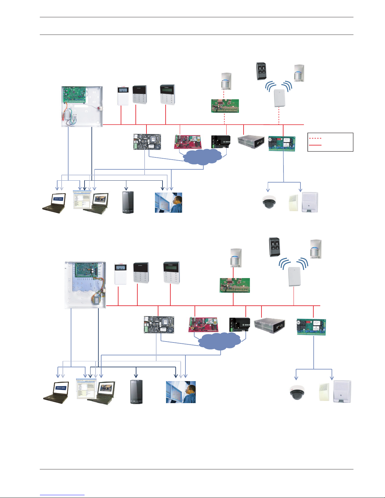
System overview
DX2010
B426
Ethernet
Video
DX4020G
PSTN
GSM/
GPRS
AMAX 3000
AMAX 2100 / 3000
RADION
DX3010
Text KeypadLCD / LED Keypad
DX4010V2
B450
(B442/B443)
GPRS
USB
IP
DSL
Public
IP network
Option bus
A-Link Plus CMSAMAX SDK Telephone
Signaling
Figure 3.1: AMAX 2100 / 3000 overview
DX2010
Option bus
Video
RADION
DX3010
Text KeypadLCD / LED Keypad
DX4010V2
B426
Ethernet
DX4020G
PSTN
GSM/
GPRS
B450
(B442/B443)
GPRS
A-Link Plus CMSAMAX SDK
USB
IP
DSL
Public
IP network
Telephone
Signaling
Figure 3.2: AMAX 3000 BE / 4000 overview
3
AMAX panel System overview | en 7
Bosch Sicherheitssysteme GmbH Quick Installation Guide 2016.05 | 06 | F.01U.309.297
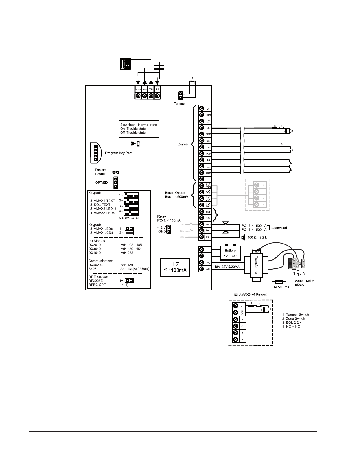
Wiring diagrams
4
/ B450
≤ 500mA
Figure 3.3: Wiring diagram AMAX 2100 / 3000
8 en | System overview AMAX panel
2016.05 | 06 | F.01U.309.297 Quick Installation Guide Bosch Sicherheitssysteme GmbH
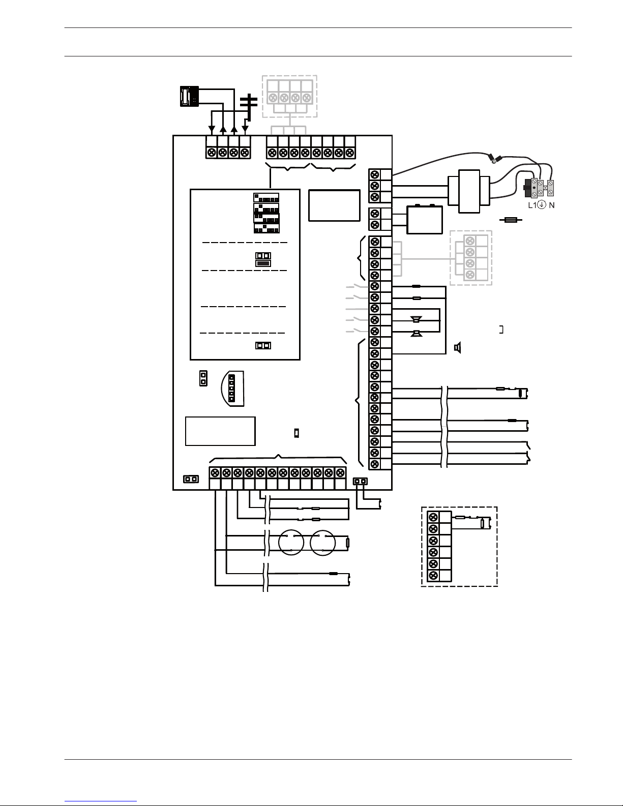
Program Key Port
GND
-
+
AC
AC
Transformer
Battery
Tamper
L2 COM
COM
COM
L1a
L3
L4
L5
L6
L7
L8
L9
COM
COM
COM
COM
L10
L11
L12
L13
L14
L15
L16
P0+4
R
B
G
Y
AUX1
-
AUX2
-
AUX1
+12V
Y
G
B
R
RINGRHTHTIP
L1b
P0+3
P0+
P0-2
P0-1
Zones
Bosch Option
Bus 2 < 900mA
+12V
+
0 V
1
2
3
3
1 Tamper Switch
2 Zone Switch
3 EOL 2,2 k
4 NO + NC
3
2
Fuse 1 A
PO+4: < 750mA
PO+3: < 750mA
PO -2: < 500mA
PO -1: < 500mA
230V ~50Hz
230mA
Wachdog
output
<100mA
12V < 18Ah
18VAC@50VA
Zones
AUX 1: < 900mA
AUX 2: < 900mA
AUX Power
Fire
Intrusion
3
3
2
Slow flash: Normal state
On: Trouble state
Off: Trouble state
_
_
_
_
_
_
_
_
+12V
+12V
+12V
COM
_
12V 7Ah
AUX2
+12V
_
COM
supervised
PO-5
Z1
2
2
3
3
Keypads:
IUI-AMAX4-TEXT
IUI-SOL-TEXT
IUI-AMAX3-LED16
IUI-AMAX3-LED8
Keypads:
IUI-AMAX-LED8
IUI-AMAX-LCD8
I/O Moduls:
DX2010 Adr. 103 - 108
DX3010 Adr. 150 - 151
DX4010 Adr. 253
Communicators:
DX4020G Adr. 134
B426 / B450 Adr. 134(6) / 250(9)
RF Receiver:
RF3227E 1=
RFRC-OPT 1= (1)
1 =
2 =
3 =
4 =
1 =
2 =
Bosch Option
Bus 1 < 900mA
COM
R
B
G
Y
R
B
G
Y
R
B
G
Y
♥
IUI-AMAX3 +4 Keypad
3
1
2
1
Factory
Default
5-16 Inst. Guide
I
2000mA
100 Ω - 2,2 k
_
<
∑
3
4
Figure 3.4: Wiring diagram AMAX 3000 BE / 4000
AMAX panel
System overview | en 9
Bosch Sicherheitssysteme GmbH Quick Installation Guide 2016.05 | 06 | F.01U.309.297
 Loading...