


OBJ_BUCH-1993-004.book Page 1 Wednesday, September 14, 2016 9:08 AM
|
L |
E |
A |
N |
C |
|
|||
|
|
|||
|
|
|
||
|
|
|
|
Robert Bosch Power Tools GmbH
70538 Stuttgart
GERMANY
0 607 661 ...
www.bosch-pt.com
... 505 | ... 506 | ... 507 | ... 509 | ... 510
1 609 92A 37T (2014.04) AS / 350 UNI
|
|
|
|
|
|
|
de |
Originalbetriebsanleitung |
sk |
Pôvodný návod na použitie |
lv |
Instrukcijas oriģinālvalodā |
|
en |
Original instructions |
hu |
Eredeti használati utasítás |
lt |
Originali instrukcija |
|
fr |
Notice originale |
ru |
Оригинальное руководство по |
cn |
|
|
es |
Manual original |
|
эксплуатации |
tw |
|
|
pt |
Manual original |
uk |
Оригінальна інструкція з |
|||
ko |
|
|||||
it |
Istruzioni originali |
|
експлуатації |
|||
|
th |
|
||||
nl |
Oorspronkelijke gebruiksaanwijzing |
kk |
Пайдалану нұсқаулығының |
|||
da |
Original brugsanvisning |
|
түпнұсқасы |
id |
Petunjuk-Petunjuk untuk Penggunaan |
|
sv |
Bruksanvisning i original |
ro |
Instrucţiuni originale |
|
Orisinal |
|
no |
Original driftsinstruks |
bg |
Оригинална инструкция |
vi |
Bản gốc hướng dẫn sử dụng |
|
fi |
Alkuperäiset ohjeet |
mk |
Оригинално упатство за работа |
ar |
ςТЎϩХʉ ЌТϾϦφЍʉ ʌμВТЎϺυ |
|
el |
Πρωτότυπο οδηγιών χρήσης |
sr |
Originalno uputstvo za rad |
fa |
ΖЎϩʉ ˒μВЖЙʉʓ И ϞφЁʑ |
|
tr |
Orijinal işletme talimatı |
sl |
Izvirna navodila |
|
|
|
pl |
Instrukcja oryginalna |
hr |
Originalne upute za rad |
|
|
|
cs |
Původní návod k používání |
et |
Algupärane kasutusjuhend |
|
|
OBJ_BUCH-1993-004.book Page 2 Wednesday, September 14, 2016 9:08 AM
2 |
Deutsch. . . . . . . . . . . . . . . . . . . . . . . . . . . . . . . . . . . . . |
. . . . Seite |
6 |
English . . . . . . . . . . . . . . . . . . . . . . . . . . . . . . . . . . . . . . |
. . . .Page |
16 |
Français . . . . . . . . . . . . . . . . . . . . . . . . . . . . . . . . . . . . . |
. . . .Page |
26 |
Español . . . . . . . . . . . . . . . . . . . . . . . . . . . . . . . . . . . . . . |
. . Página |
36 |
Português . . . . . . . . . . . . . . . . . . . . . . . . . . . . . . . . . . . . |
. . Página |
46 |
Italiano . . . . . . . . . . . . . . . . . . . . . . . . . . . . . . . . . . . . . . |
. . Pagina |
55 |
Nederlands . . . . . . . . . . . . . . . . . . . . . . . . . . . . . . . . . . . |
. . Pagina |
65 |
Dansk . . . . . . . . . . . . . . . . . . . . . . . . . . . . . . . . . . . . . . . |
. . . . Side |
74 |
Svenska . . . . . . . . . . . . . . . . . . . . . . . . . . . . . . . . . . . . . |
. . . . Sida |
83 |
Norsk. . . . . . . . . . . . . . . . . . . . . . . . . . . . . . . . . . . . . . . . |
. . . . Side |
91 |
Suomi . . . . . . . . . . . . . . . . . . . . . . . . . . . . . . . . . . . . . . . |
. . . . Sivu |
99 |
Ελληνικά . . . . . . . . . . . . . . . . . . . . . . . . . . . . . . . . . . . . . |
. . Σελίδα |
107 |
Türkçe . . . . . . . . . . . . . . . . . . . . . . . . . . . . . . . . . . . . . . . |
. . . Sayfa |
117 |
Polski . . . . . . . . . . . . . . . . . . . . . . . . . . . . . . . . . . . . . . . |
. . Strona |
126 |
Česky . . . . . . . . . . . . . . . . . . . . . . . . . . . . . . . . . . . . . . . |
. . Strana |
136 |
Slovensky . . . . . . . . . . . . . . . . . . . . . . . . . . . . . . . . . . . . |
. . Strana |
145 |
Magyar . . . . . . . . . . . . . . . . . . . . . . . . . . . . . . . . . . . . . . |
. . . Oldal |
155 |
Русский . . . . . . . . . . . . . . . . . . . . . . . . . . . . . . . . . . . . |
Страница |
164 |
Українська . . . . . . . . . . . . . . . . . . . . . . . . . . . . . . . . . . . |
Сторінка |
175 |
Қазақша . . . . . . . . . . . . . . . . . . . . . . . . . . . . . . . . . . . . . |
. . . . . Бет |
185 |
Română. . . . . . . . . . . . . . . . . . . . . . . . . . . . . . . . . . . . . . |
. . Pagina |
195 |
Български . . . . . . . . . . . . . . . . . . . . . . . . . . . . . . . . . . |
Страница |
204 |
Македонски . . . . . . . . . . . . . . . . . . . . . . . . . . . . . . . . . |
. . Страна |
214 |
Srpski . . . . . . . . . . . . . . . . . . . . . . . . . . . . . . . . . . . . . . . |
. . Strana |
224 |
Slovensko . . . . . . . . . . . . . . . . . . . . . . . . . . . . . . . . . . . . |
. . . Stran |
233 |
Hrvatski. . . . . . . . . . . . . . . . . . . . . . . . . . . . . . . . . . . . . . |
. Stranica |
241 |
Eesti . . . . . . . . . . . . . . . . . . . . . . . . . . . . . . . . . . . . . . . . |
Lehekülg |
250 |
Latviešu . . . . . . . . . . . . . . . . . . . . . . . . . . . . . . . . . . . . . |
.Lappuse |
258 |
Lietuviškai. . . . . . . . . . . . . . . . . . . . . . . . . . . . . . . . . . . . |
. Puslapis |
268 |
. . . . . . . . . . . . . . . . . . . |
. . |
277 |
. . . . . . . . . . . . . . . . . . . |
. . . |
285 |
. . . . . . . . . . . . . . . . . . . . . . . |
. |
293 |
. . . . . . . . . . . . . . . . . . . . . . . . . . . . . |
. . . . |
302 |
Bahasa Indonesia . . . . . . . . . . . . . . . . . . . . . . . . . . . . . . |
Halaman |
311 |
Tiếng Việt . . . . . . . . . . . . . . . . . . . . . . . . . . . . |
. Trang |
321 |
. . . . . . . . . . . . . . . . . . . . . . . . . . . . . |
. |
339 |
. . . . . . . . . . . . . . . . . . . . . . . . . . . . . |
. |
349 |
|
1 609 92A 37T | (14.9.16) |
|
|
Bosch Power Tools |
|||
|
|
|
|
|
|
|
|
|
|
|
|
|
|
|
|
|
|
|
|
|
|
|
|
OBJ_BUCH-1993-004.book Page 3 Wednesday, September 14, 2016 9:08 AM |
|
|
|
|
|
||
3 | |
|
|
|
|
|
|
|
12 |
|
|
|
|
|
|
|
|
|
11 |
|
|
|
|
10 |
|
|
|
|
|
|
|
|
|
|
|
|
|
|
|
9 |
|
|
|
• |
• |
• |
• |
• |
|
|
|
|
||||
|
|
|
|
|
|||
|
|
|
|
|
|
||
|
|
|
|
|
|
|
|
|
|
|
|
|
|
|
8 |
|
|
3 |
|
|
|
|
|
1 |
2 |
4 |
|
|
|
|
|
0 607 661 505 |
|
|
|
|
|
|
|
0 607 661 507 |
|
|
|
|
|
|
|
0 607 661 509 |
|
|
|
|
|
|
7 |
|
|
|
|
|
|
|
|
|
|
5 |
|
|
|
|
6 |
|
|
|
|
|
|
|
|
12 |
|
|
|
|
|
|
|
|
|
11 |
|
|
|
|
10 |
|
|
|
|
|
|
|
|
|
|
|
|
|
|
|
9 |
|
|
|
• |
• |
• |
• |
• |
|
|
|
|
||||
|
|
|
|
|
|||
|
|
|
|
|
|
||
|
|
|
|
|
|
|
|
|
|
|
|
|
|
|
8 |
2 |
13 |
3 |
|
|
|
|
|
1 |
|
4 |
|
|
|
|
|
|
|
|
|
|
|
|
|
0 607 661 506 |
|
|
|
|
|
|
7 |
0 607 661 510 |
|
5 |
|
|
|
|
6 |
|
|
|
|
|
|
||
|
|
|
|
|
|
|
|
1 609 92A 37T | (14.9.16) |
|
|
|
|
|
|
Bosch Power Tools |

OBJ_BUCH-1993-004.book Page 4 Wednesday, September 14, 2016 9:08 AM |
|
|||
4 | |
|
|
|
|
A |
|
|
|
|
|
14 |
|
|
|
|
|
|
15 |
14 |
|
|
|
9 |
|
|
• |
• |
|
|
B |
|
C |
|
|
|
|
|
6 |
|
|
|
|
|
16 |
6 |
|
|
18 |
|
16 |
|
|
|
|
|
|
|
|
|
17 |
|
|
|
|
D |
|
E |
|
|
|
|
|
13 |
|
1 |
2 |
1 |
2 |
|
1 609 92A 37T | (14.9.16) |
|
|
|
Bosch Power Tools |
 OBJ_BUCH-1993-004.book Page 5 Wednesday, September 14, 2016 9:08 AM
5 | |
|
|
|
|
|
F |
|
|
|
|
|
|
R |
|
|
|
|
|
|
|
|
|
L |
|
|
|
|
|
10 |
|
• |
• |
• |
• |
• |
|
|
||||
|
|
|
|||
|
|
|
|
||
|
|
|
|
|
|
H |
0 607 661 505 |
|
|||
|
0 607 661 507 |
|
|||
0 607 661 509
25 26
24
22
3 21 

27 
 28
28 
34 |
29 |
30 

31 
 32
32 


33
J
38
24
0 607 661 507
G |
• |
• • • |
• |
|
|||
|
|
|
|
|
|
|
20 |
|
|
|
19 |
|
|
|
8 |
I |
0 607 661 506 |
||
|
0 607 661 510 |
||
13
37 35 36 
26
25
24 23
22
3 21 

27 
 28
28 
34 |
29 |
30 

31 
 32
32 


33
|
1 609 92A 37T | (14.9.16) |
|
|
Bosch Power Tools |
|||
|
|
|
|
|
|
|
|
|
|
|
|
|
|
|
|
|
|
|
|
|
|
|
|

OBJ_BUCH-1993-004.book Page 6 Wednesday, September 14, 2016 9:08 AM
6 | Deutsch
Deutsch
Sicherheitshinweise
Allgemeine Sicherheitshinweise für Druckluftwerkzeuge
WARNUNG |
Lesen und beachten Sie vor dem Ein- |
|
bau, dem Betrieb, der Reparatur, der |
||
|
Wartung und dem Austausch von Zubehörteilen sowie vor der Arbeit in der Nähe des Druckluftwerkzeugs alle Hinweise. Bei Nichtbeachtung der folgenden Sicherheitshinweise können ernsthafte Verletzungen die Folge sein.
Bewahren Sie die Sicherheitshinweise gut auf und geben Sie sie der Bedienperson.
Arbeitsplatzsicherheit
Achten Sie auf Oberflächen, die durch den Gebrauch der Maschine rutschig geworden sein können, und auf durch den Luftoder den Hydraulikschlauch bedingte Stolpergefahren. Ausrutschen, Stolpern und Stürzen sind Hauptgründe für Verletzungen am Arbeitsplatz.
Arbeiten Sie mit dem Druckluftwerkzeug nicht in explosionsgefährdeter Umgebung, in der sich brennbare Flüssigkeiten, Gase oder Staub befinden. Beim Bearbeiten des Werkstücks können Funken entstehen, die den Staub oder die Dämpfe entzünden.
Halten Sie Zuschauer, Kinder und Besucher von Ihrem Arbeitsplatz fern, wenn Sie das Druckluftwerkzeug benutzen. Bei Ablenkung durch andere Personen können Sie die Kontrolle über das Druckluftwerkzeug verlieren.
Sicherheit von Druckluftwerkzeugen
Richten Sie den Luftstrom niemals auf sich selbst oder gegen andere Personen und leiten Sie kalte Luft von den Händen fort. Druckluft kann ernsthafte Verletzungen verursachen.
Kontrollieren Sie Anschlüsse und Versorgungsleitungen. Sämtliche Wartungseinheiten, Kupplungen und Schläuche müssen in Bezug auf Druck und Luftmenge entsprechend den technischen Daten ausgelegt sein. Zu geringer Druck beeinträchtigt die Funktion des Druckluftwerkzeugs, zu hoher Druck kann zu Sachschäden und zu Verletzungen führen.
Schützen Sie die Schläuche vor Knicken, Verengungen, Lösungsmitteln und scharfen Kanten. Halten Sie die Schläuche fern von Hitze, Öl und rotierenden Teilen. Ersetzen Sie einen beschädigten Schlauch unverzüglich. Eine schadhafte Versorgungsleitung kann zu einem herumschlagenden Druckluftschlauch führen und kann Verletzungen verursachen. Aufgewirbelter Staub oder Späne können schwere Augenverletzungen hervorrufen.
Achten Sie darauf, dass Schlauchschellen immer fest angezogen sind. Nicht fest gezogene oder beschädigte Schlauchschellen können die Luft unkontrolliert entweichen lassen.
Sicherheit von Personen
Seien Sie aufmerksam, achten Sie darauf, was Sie tun und gehen Sie mit Vernunft an die Arbeit mit einem Druckluftwerkzeug. Benutzen Sie kein Druckluftwerkzeug, wenn Sie müde sind oder unter dem Einfluss von Drogen, Alkohol oder Medikamenten stehen. Ein Moment der Unachtsamkeit beim Gebrauch des Druckluftwerkzeugs kann zu ernsthaften Verletzungen führen.
Tragen Sie persönliche Schutzausrüstung und immer eine Schutzbrille. Das Tragen persönlicher Schutzausrüstung, wie Atemschutz, rutschfeste Sicherheitsschuhe, Schutzhelm oder Gehörschutz, nach den Anweisungen Ihres Arbeitgebers oder wie nach den Arbeitsund Gesundheitsschutzvorschriften gefordert, verringert das Risiko von Verletzungen.
Vermeiden Sie eine unbeabsichtigte Inbetriebnahme. Vergewissern Sie sich, dass das Druckluftwerkzeug ausgeschaltet ist, bevor Sie es an die Luftversorgung anschließen, es aufnehmen oder tragen. Wenn Sie beim Tragen des Druckluftwerkzeugs den Finger am Ein-/Aus- schalter haben oder das Druckluftwerkzeug eingeschaltet an die Luftversorgung anschließen, kann dies zu Unfällen führen.
Entfernen Sie Einstellwerkzeuge, bevor Sie das Druckluftwerkzeug einschalten. Ein Einstellwerkzeug, das sich in einem drehenden Teil des Druckluftwerkzeugs befindet, kann zu Verletzungen führen.
Überschätzen Sie sich nicht. Sorgen Sie für einen sicheren Stand und halten Sie jederzeit das Gleichgewicht. Ein sicherer Stand und geeignete Körperhaltung lassen Sie das Druckluftwerkzeug in unerwarteten Situationen besser kontrollieren.
Tragen Sie geeignete Kleidung. Tragen Sie keine weite Kleidung oder Schmuck. Halten Sie Haare, Kleidung und Handschuhe fern von sich bewegenden Teilen. Lockere Kleidung, Schmuck oder lange Haare können von sich bewegenden Teilen erfasst werden.
Atmen Sie die Abluft nicht direkt ein. Vermeiden Sie es, die Abluft in die Augen zu bekommen. Die Abluft des Druckluftwerkzeugs kann Wasser, Öl, Metallpartikel und Verunreinigungen aus dem Kompressor enthalten. Dies kann Gesundheitsschäden verursachen.
Sorgfältiger Umgang mit und Gebrauch von Druckluftwerkzeugen
Benutzen Sie Spannvorrichtungen oder einen Schraubstock, um das Werkstück festzuhalten und abzustützen. Wenn Sie das Werkstück mit der Hand festhalten oder an den Körper drücken, können Sie das Druckluftwerkzeug nicht sicher bedienen.
Überlasten Sie das Druckluftwerkzeug nicht. Verwenden Sie für Ihre Arbeit das dafür bestimmte Druckluftwerkzeug. Mit dem passenden Druckluftwerkzeug arbeiten Sie besser und sicherer im angegebenen Leistungsbereich.
|
1 609 92A 37T | (14.9.16) |
|
|
Bosch Power Tools |
|||
|
|
|
|
|
|
|
|
|
|
|
|
|
|
|
|
|
|
|
|
|
|
|
|

OBJ_BUCH-1993-004.book Page 7 Wednesday, September 14, 2016 9:08 AM
Benutzen Sie kein Druckluftwerkzeug, dessen Ein- /Ausschalter defekt ist. Ein Druckluftwerkzeug, das sich nicht mehr einoder ausschalten lässt, ist gefährlich und muss repariert werden.
Unterbrechen Sie die Luftversorgung, bevor Sie Geräteeinstellungen vornehmen, Zubehörteile wechseln oder bei längerem Nichtgebrauch. Diese Vorsichtsmaßnahme verhindert den unbeabsichtigten Start des Druckluftwerkzeugs.
Bewahren Sie unbenutzte Druckluftwerkzeuge außerhalb der Reichweite von Kindern auf. Lassen Sie Personen das Druckluftwerkzeug nicht benutzen, die mit diesem nicht vertraut sind oder diese Anweisungen nicht gelesen haben. Druckluftwerkzeuge sind gefährlich, wenn sie von unerfahrenen Personen benutzt werden.
Pflegen Sie das Druckluftwerkzeug mit Sorgfalt. Kontrollieren Sie, ob bewegliche Geräteteile einwandfrei funktionieren und nicht klemmen, und ob Teile gebrochen oder so beschädigt sind, dass die Funktion des Druckluftwerkzeugs beeinträchtigt ist. Lassen Sie beschädigte Teile vor dem Einsatz des Druckluftwerkzeugs reparieren. Viele Unfälle haben ihre Ursache in schlecht gewarteten Druckluftwerkzeugen.
Verwenden Sie Druckluftwerkzeug, Zubehör, Einsatzwerkzeuge usw. entsprechend diesen Anweisungen. Berücksichtigen Sie dabei die Arbeitsbedingungen und die auszuführende Tätigkeit. Damit werden Staubentwicklung, Schwingungen und Geräuschentwicklung soweit wie möglich reduziert.
Das Druckluftwerkzeug sollte ausschließlich von qualifizierten und geschulten Bedienern eingerichtet, eingestellt oder verwendet werden.
Das Druckluftwerkzeug darf nicht verändert werden.
Veränderungen können die Wirksamkeit der Sicherheitsmaßnahmen verringern und die Risiken für den Bediener erhöhen.
Service
Lassen Sie Ihr Druckluftwerkzeug nur von qualifiziertem Fachpersonal und nur mit Original-Ersatzteilen reparieren. Damit wird sichergestellt, dass die Sicherheit des Druckluftwerkzeugs erhalten bleibt.
Sicherheitshinweise für Druckluft-Impulsschrau- ber
Kontrollieren Sie, ob das Typenschild lesbar ist. Besorgen Sie sich gegebenenfalls Ersatz vom Hersteller.
Bei einem Bruch des Werkstücks oder eines der Zubehörteile oder gar des Druckluftwerkzeugs selbst können Teile mit hoher Geschwindigkeit herausgeschleudert werden.
Beim Betrieb sowie bei Reparaturoder Wartungsarbeiten und beim Austausch von Zubehörteilen am Druckluftwerkzeug ist immer ein schlagfester Augenschutz zu tragen. Der Grad des erforderlichen Schutzes sollte für jeden einzelnen Einsatz gesondert bewertet werden.
Deutsch | 7
Schalten Sie das Druckluftwerkzeug nie ein, während Sie es tragen. Eine rotierende Werkzeugaufnahme kann Kleidung oder Haare aufwickeln und zu Verletzungen führen.
Tragen Sie enganliegende Handschuhe. Handgriffe von Druckluftwerkzeugen werden durch die Druckluftströmung kalt. Warme Hände sind unempfindlicher gegen Vibrationen. Weite Handschuhe können von rotierenden Teilen erfasst werden.
Halten Sie Ihre Hände von den Fassungen der Steckschlüssel und sich drehenden Einsatzwerkzeugen fern. Halten Sie niemals das rotierende Einsatzwerkzeug oder den Antrieb fest. Sie können sich verletzen.
Seien Sie vorsichtig bei beengten Arbeitsverhältnissen. Aufgrund von Reaktionsdrehmomenten können Verletzungen durch Einklemmen oder Quetschen entstehen.
Die Bediener und das Wartungspersonal müssen physisch in der Lage sein, die Größe, das Gewicht und die Leistung des Druckluftwerkzeugs zu handhaben.
Seien Sie auf unerwartete Bewegungen des Druckluftwerkzeugs gefasst, die infolge von Reaktionskräften oder dem Bruch des Einsatzwerkzeugs entstehen können. Halten Sie das Druckluftwerkzeug gut fest und bringen Sie Ihren Körper und Ihre Arme in eine Position, in der Sie diese Bewegungen abfangen können. Diese Vorsichtsmaßnahmen können Verletzungen vermeiden.
Verwenden Sie Hilfsmittel zur Aufnahme von Reaktionsmomenten, wie z.B. eine Abstützvorrichtung. Falls dies nicht möglich ist verwenden Sie einen Zusatzhandgriff.
Bei einer Unterbrechung der Luftversorgung oder reduziertem Betriebsdruck schalten Sie das Druckluftwerkzeug aus. Prüfen Sie den Betriebsdruck und starten Sie bei optimalem Betriebsdruck erneut.
Bei der Verwendung des Druckluftwerkzeugs kann der Bediener bei der Ausführung arbeitsbezogener Tätigkeiten unangenehme Empfindungen in den Händen, Armen, Schultern, im Halsbereich oder an anderen Körperteilen erfahren.
Nehmen Sie für die Arbeit mit diesem Druckluftwerkzeug eine bequeme Stellung ein, achten Sie auf sicheren Halt und vermeiden Sie ungünstige Positionen oder solche, bei denen es schwierig ist, das Gleichgewicht zu halten. Der Bediener sollte während lang dauernder Arbeiten die Körperhaltung verändern, was helfen kann, Unannehmlichkeiten und Ermüdung zu vermeiden.
Falls der Bediener Symptome wie z. B. andauerndes Unwohlsein, Beschwerden, Pochen, Schmerz, Kribbeln, Taubheit, Brennen oder Steifheit an sich wahrnimmt, sollten diese warnenden Anzeichen nicht ignoriert werden. Der Bediener sollte diese seinem Arbeitgeber mitteilen und einen qualifizierten Mediziner konsultieren.
Berühren Sie keine Fassungen oder Zubehörteile während des Schlagvorgangs, weil dies die Gefährdung durch Schneiden, Verbrennen oder Verletzungen durch Schwingungen erhöhen kann.
|
Bosch Power Tools |
|
|
1 609 92A 37T | (14.9.16) |
|||
|
|
|
|
|
|
|
|
|
|
|
|
|
|
|
|
|
|
|
|
|
|
|
|
OBJ_BUCH-1993-004.book Page 8 Wednesday, September 14, 2016 9:08 AM
8 | Deutsch
Verwenden Sie ausschließlich Schlagfassungen in gutem Arbeitszustand. Ein mangelhafter Zustand von Handfassungen und Zubehörteilen kann dazu führen, dass diese bei der Verwendung mit Schlagoder Impulsschraubern zerbrechen und herausgeschleudert werden.
Vermeiden Sie den Kontakt mit einer spannungsführenden Leitung. Das Druckluftwerkzeug ist nicht isoliert, und der Kontakt mit einer spannungsführenden Leitung kann zu einem elektrischen Schlag führen.
WARNUNG |
Der beim Schmirgeln, Sägen, Schlei- |
|
fen, BohrenundähnlichenTätigkeiten |
||
|
entstehende Staub kann krebserzeugend, fruchtschädigend oder erbgutverändernd wirken. Einige der in diesen Stäuben enthaltenen Stoffe sind:
–Blei in bleihaltigen Farben und Lacken;
–kristalline Kieselerde in Ziegeln, Zement und anderen Maurerarbeiten;
–Arsen und Chromat in chemisch behandeltem Holz.
Das Risiko einer Erkrankung hängt davon ab, wie oft Sie diesen Stoffen ausgesetzt sind. Um die Gefahr zu reduzieren, sollten Sie nur in gut belüfteten Räumen mit entsprechender Schutzausrüstung arbeiten (z.B. mit speziell konstruierten Atemschutzgeräten, die auch kleinste Staubpartikel herausfiltern).
Tragen Sie Gehörschutz. Die Einwirkung von Lärm kann Gehörverlust bewirken.
Beim Arbeiten am Werkstück kann zusätzliche Lärmbelastung entstehen, die durch geeignete Maßnahmen vermieden werden kann, wie z.B. die Verwendung von Dämmstoffen beim Auftreten von Klingelgeräuschen am Werkstück.
Verfügt das Druckluftwerkzeug über einen Schalldämpfer, ist stets sicherzustellen, dass dieser beim Betrieb des Druckluftwerkzeugs vor Ort ist und sich in einem guten Arbeitszustand befindet.
Die Einwirkung von Schwingungen kann Schädigungen an den Nerven und Störungen der Blutzirkulation in Händen und Armen verursachen.
Falls Sie feststellen, dass die Haut an Ihren Fingern oder Händen taub wird, kribbelt, schmerzt oder sich weiß verfärbt, stellen Sie die Arbeit mit dem Druckluftwerkzeug ein, benachrichtigen Sie Ihren Arbeitgeber und konsultieren Sie einen Arzt.
Verwenden Sie keine verschlissenen oder schlecht passenden Fassungen und Verlängerungen. Dies kann zu einer Verstärkung der Schwingungen führen.
Nutzen Sie zum Halten des Gewichts des Druckluftwerkzeugs, wenn möglich, einen Ständer, einen Federzug oder eine Ausgleichseinrichtung.
Halten Sie das Druckluftwerkzeug mit nicht allzu festem, aber sicherem Griff unter Einhaltung der erforderlichen Hand-Reaktionskräfte. Die Schwingungen können sich verstärken, je fester Sie das Werkzeug halten.
Falls Universal-Drehkupplungen (Klauenkupplungen) verwendet werden, müssen Arretierstifte eingesetzt werden. Verwenden Sie Whipcheck-Schlauchsicherun- gen, um Schutz für den Fall eines Versagens der Ver-
bindung des Schlauchs mit dem Druckluftwerkzeug oder von Schläuchen untereinander zu bieten.
Tragen Sie das Druckluftwerkzeug niemals am Schlauch.
Wenn Sie das Druckluftwerkzeug in einer Aufhängeoder Einspannvorrichtung betreiben wollen, achten Sie darauf, es erst in der Vorrichtung zu befestigen, bevor Sie es an die Luftversorgung anschließen. Dadurch vermeiden Sie, es unbeabsichtigt in Betrieb zu nehmen.
Symbole
Die nachfolgenden Symbole können für den Gebrauch Ihres Druckluftwerkzeugs von Bedeutung sein. Prägen Sie sich bitte die Symbole und ihre Bedeutung ein. Die richtige Interpretation der Symbole hilft Ihnen, das Druckluftwerkzeug besser und sicherer zu gebrauchen.
Symbol |
|
|
Bedeutung |
|
||
|
|
|
|
Lesen und beachten Sie vor dem |
||
|
|
|
|
|||
|
|
|
|
Einbau, dem Betrieb, der Repara- |
||
|
|
|
|
tur, der Wartung und dem Aus- |
||
|
|
|
|
tausch von Zubehörteilen sowie |
||
|
|
|
|
vor der Arbeit in der Nähe des |
||
|
|
|
|
Druckluftwerkzeugs alle Hinweise. |
||
|
|
|
|
Bei Nichtbeachtung der Sicherheits- |
||
|
|
|
|
hinweise und Anweisungen können |
||
|
|
|
|
ernsthafte Verletzungen die Folge |
||
|
|
|
|
sein. |
|
|
|
|
|
|
Tragen Sie eine Schutzbrille. |
||
|
|
|
|
|
|
|
W |
Watt |
Leistung |
||||
Nm |
Newtonmeter |
Energieeinheit |
||||
(Drehmoment) |
||||||
|
|
|
|
|
||
kg |
Kilogramm |
Masse, Gewicht |
||||
lbs |
Pounds |
|||||
|
||||||
|
|
|
|
|
|
|
mm |
Millimeter |
Länge |
||||
min |
Minuten |
Zeitspanne, Dauer |
||||
s |
Sekunden |
|||||
|
||||||
min-1 |
Umdrehungen oder |
Leerlaufdrehzahl |
||||
|
|
Bewegungen pro Minute |
|
|||
bar |
bar |
Luftdruck |
||||
psi |
pounds per square inch |
|||||
|
||||||
|
|
|
|
|
|
|
l/s |
Liter pro Sekunde |
Luftverbrauch |
||||
cfm |
cubic feet/minute |
|||||
|
||||||
dB |
Dezibel |
Bes. Maß der |
||||
relativen Lautstärke |
||||||
|
|
|
|
|
||
|
1 609 92A 37T | (14.9.16) |
|
|
Bosch Power Tools |
|||
|
|
|
|
|
|
|
|
|
|
|
|
|
|
|
|
|
|
|
|
|
|
|
|

OBJ_BUCH-1993-004.book Page 9 Wednesday, September 14, 2016 9:08 AM
Symbol |
Bedeutung |
||||
SWF |
Schnellwechselfutter |
||||
|
|
|
Symbol für Innensechskant |
|
|
|
Symbol für Außenvierkant |
Werkzeugaufnahme |
|||
|
|
|
US-Feingewinde |
||
UNF |
(Unified National Fine |
||||
|
|
|
Thread Series) |
||
G |
Whitworth-Gewinde |
||||
NPT |
|
Anschlussgewinde |
|||
National pipe thread |
|||||
|
|
|
Rechtslauf |
||
|
|
|
|||
R |
|||||
|
Drehrichtung |
||||
|
|
|
|
||
|
|
|
Linkslauf |
||
L |
|||||
|
|
||||
Produktund Leistungsbeschreibung
Lesen Sie alle Sicherheitshinweise und Anweisungen. Versäumnisse bei der Einhaltung
der Sicherheitshinweise und Anweisungen
können elektrischen Schlag, Brand und/oder schwere Verletzungen verursachen.
Bitte klappen Sie die Aufklappseite mit der Darstellung des Druckluftwerkzeugs auf, und lassen Sie diese Seite aufgeklappt, während Sie die Betriebsanleitung lesen.
Bestimmungsgemäßer Gebrauch
Das Druckluftwerkzeug ist bestimmt zum Eindrehen und Lösen von Schrauben sowie zum Anziehen und Lösen von Muttern im angegebenen Abmessungsund Leistungsbereich.
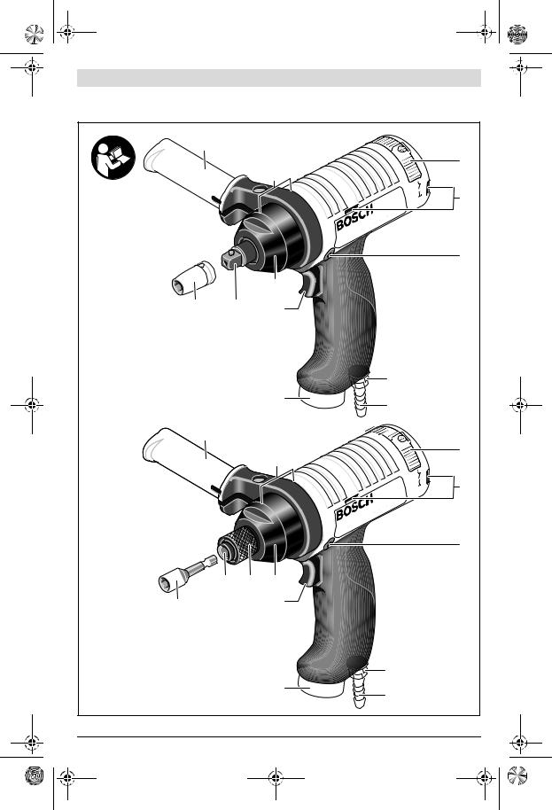
Abgebildete Komponenten
Die Nummerierung der abgebildeten Komponenten bezieht sich auf die Darstellungen auf der Grafikseite. Die Darstellungen sind teilweise schematisch und können bei Ihrem Druckluftwerkzeug abweichen.
1 Einsatzwerkzeug
2 Werkzeugaufnahme
3 Gehäuse mit Impulswerk
4 Ein-/Ausschalter
5 Luftaustritt mit Schalldämpfer
6 Schlauchnippel
7 Anschlussstutzen am Lufteinlass
8 Verschlussschraube
9 Befestigungsschlitze für Aufhängebügel
10Schieber für Drehrichtung (Rechts-/Linkslauf)
11Einspannbereich(z.B. für einen Zusatzgriff)
12Zusatzgriff*
13Hülse des Schnellwechselfutters
14Aufhängebügel
15Abstandshalter
16Schlauchschelle
17Abluftschlauch
Deutsch | 9
18Zuluftschlauch
19Innensechskantschlüssel
20Einstellschraube Drehmoment
21Sicherungsring Gehäuse
22Sicherungsring Nockenwelle
23Kugel
24Nockenwelle
25Dichtring Nockenwelle
26Impulswerk
27Sicherungsring Kolben
28Kolben
29Dichtring Kolben
30Kolbendeckel
31Dichtring Kolbendeckel
32Befestigungsschraube Kolbendeckel
33Sicherungsring Kolbendeckel
34Schlüsselfläche am Gehäuse
35Sicherungsring Schnellwechselfutter
36Stahlring
37Druckfeder
38Oberer Kolbenrand
*Abgebildetes oder beschriebenes Zubehör gehört nicht zum Standard-Lieferumfang. Das vollständige Zubehör finden Sie in unserem Zubehörprogramm.
Konformitätserklärung
Wir erklären in alleiniger Verantwortung, dass das unter „Technische Daten“ beschriebene Produkt mit den folgenden Normen oder normativen Dokumenten übereinstimmt:
EN ISO 11148 gemäß den Bestimmungen der Richtlinie 2006/42/EG.
Technische Unterlagen (2006/42/EG) bei: Robert Bosch Power Tools GmbH, PT/ECS, 70538 Stuttgart, GERMANY
Henk Becker |
Helmut Heinzelmann |
Executive Vice President |
Head of Product Certification |
Engineering |
PT/ECS |
Robert Bosch Power Tools GmbH
70538 Stuttgart, GERMANY
Stuttgart, 01.01.2017
|
Bosch Power Tools |
|
|
1 609 92A 37T | (14.9.16) |
|||
|
|
|
|
|
|
|
|
|
|
|
|
|
|
|
|
|
|
|
|
|
|
|
|

OBJ_BUCH-1993-004.book Page 10 Wednesday, September 14, 2016 9:08 AM
10 | Deutsch
Technische Daten
Druckluft-Impulsschrauber |
|
0 607 661 ... |
|
|
|
|
|
Sachnummer |
|
... 505 |
|
... 506 |
... 507 |
... 509 |
... 510 |
Leerlaufdrehzahl |
min-1 |
4500 |
|
4500 |
4700 |
4000 |
4000 |
Abgabeleistung |
W |
400 |
|
400 |
400 |
400 |
400 |
max. Drehmoment harter Schraubfall nach |
|
|
|
|
|
|
|
ISO 5393 |
Nm |
16 –35 |
|
16 –35 |
28 –60 |
8 –18 |
8 –18 |
max. Drehmoment weicher Schraubfall nach |
|
|
|
|
|
|
|
ISO 5393 |
Nm |
12 –29 |
|
12 –29 |
16 –47 |
5 –15 |
5 –15 |
max. Schraubdurchmesser |
mm |
M 8 |
|
M 8 |
M 10 |
M 6 |
M 6 |
Rechts-/Linkslauf |
|
|
|
|
|
|
|
Werkzeugaufnahme |
|
3/8" |
|
– |
1/2" |
3/8" |
– |
– Außenvierkant |
|
|
|||||
– Schnellwechselfutter |
|
– |
|
1/4" |
– |
– |
1/4" |
Schlüsselfläche 34 am Gehäuse 3 |
mm |
32 |
|
32 |
40 |
32 |
32 |
Schlüsselfläche am Kolbendeckel 30 |
mm |
11 |
|
11 |
15 |
11 |
11 |
max. Arbeitsdruck am Werkzeug |
bar |
6,3 |
|
6,3 |
6,3 |
6,3 |
6,3 |
|
psi |
91 |
|
91 |
91 |
91 |
91 |
Anschlussgewinde des Schlauchanschlusses |
|
G 1/4" |
|
G 1/4" |
G 1/4" |
G 1/4" |
G 1/4" |
Lichte Schlauchweite |
mm |
9 |
|
9 |
9 |
6 |
6 |
Luftverbrauch im Leerlauf |
l/s |
16 |
|
16 |
17 |
16 |
16 |
|
cfm |
33,9 |
|
33,9 |
36,0 |
33,9 |
33,9 |
Gewicht entsprechend EPTA-Procedure 01:2014 |
kg |
1,1 |
|
1,1 |
1,3 |
1,1 |
1,2 |
|
lbs |
2,4 |
|
2,4 |
2,9 |
2,4 |
2,6 |
Geräusch-/Vibrationsinformation |
|
|
|
|
|
|
|
Messwerte für Geräusch ermittelt entsprechend EN ISO 15744. |
|
|
|
|
|||
Der A-bewertete Geräuschpegel des Druckluftwerk- |
|
|
|
|
|
|
|
zeugs beträgt typischerweise: |
|
|
|
|
|
|
|
Schalldruckpegel LpA |
dB(A) |
77 |
|
77 |
82 |
77 |
77 |
Schallleistungspegel LwA |
dB(A) |
88 |
|
88 |
93 |
88 |
88 |
Unsicherheit K |
dB |
3 |
|
3 |
3 |
3 |
3 |
Gehörschutz tragen!
Schwingungsgesamtwerte ah (Vektorsumme dreier Richtungen) und Unsicherheit K ermittelt entsprechend EN 28927:
Schrauben: |
m/s2 |
|
|
|
|
|
a |
< 2,5 |
< 2,5 |
< 2,5 |
< 2,5 |
< 2,5 |
|
h |
m/s2 |
1,5 |
1,5 |
1,5 |
1,5 |
1,5 |
K |
Der in diesen Anweisungen angegebene Schwingungspegel ist entsprechend einem in EN ISO 11148 genormten Messverfahren gemessen worden und kann für den Vergleich von Druckluftwerkzeugen miteinander verwendet werden. Er eignet sich auch für eine vorläufige Einschätzung der Schwingungsbelastung.
Der angegebene Schwingungspegel repräsentiert die hauptsächlichen Anwendungen des Druckluftwerkzeugs. Wenn allerdings das Druckluftwerkzeug für andere Anwendungen, mit unterschiedlichen Zubehören, mit abweichenden Einsatzwerkzeugen oder ungenügender Wartung eingesetzt wird, kann der Schwingungspegel abweichen. Dies kann die Schwingungsbelastung über den gesamten Arbeitszeitraum deutlich erhöhen.
Für eine genaue Abschätzung der Schwingungsbelastung sollten auch die Zeiten berücksichtigt werden, in denen das Druckluftwerkzeug abgeschaltet ist oder zwar läuft, aber nicht tatsächlich im Einsatz ist. Dies kann die Schwingungsbelastung über den gesamten Arbeitszeitraum deutlich reduzieren.
Legen Sie zusätzliche Sicherheitsmaßnahmen zum Schutz des Bedieners vor der Wirkung von Schwingungen fest wie zum Beispiel: Wartung von Druckluftwerkzeug und Einsatzwerkzeugen, Warmhalten der Hände, Organisation der Arbeitsabläufe.
|
1 609 92A 37T | (14.9.16) |
|
|
Bosch Power Tools |
|||
|
|
|
|
|
|
|
|
|
|
|
|
|
|
|
|
|
|
|
|
|
|
|
|
OBJ_BUCH-1993-004.book Page 11 Wednesday, September 14, 2016 9:08 AM
Diese Druckluftwerkzeuge gehören zur CLEAN-Baureihe.
Die Bosch CLEAN-Technik schont Anwender und Umwelt durch ölfreies Arbeiten sowie geringeren Luftund Energieverbrauch.
Ein Betrieb mit ölhaltiger Luft ist jedoch ebenfalls möglich.
consumption optimized |
– |
im Luftverbrauch optimiert |
lubrication free |
– |
ölfrei |
ergonomic |
– ergonomisch |
|
air tool |
– |
Druckluftwerkzeug |
noise reduction |
– |
reduzierter Geräuschpegel |
Montage
Vorrichtungen zur sicheren Handhabung
Wenn Sie das Druckluftwerkzeug in einer Aufhängeoder Einspannvorrichtung betreiben wollen, achten Sie darauf, es erst in der Vorrichtung zu befestigen, bevor Sie es an die Luftversorgung anschließen. Dadurch vermeiden Sie, es unbeabsichtigt in Betrieb zu nehmen.
Sorgen Sie dafür, dass der Zusatzgriff bzw. die Einspannvorrichtung das Druckluftwerkzeug sicher und fest hält.
Überlasten Sie den Einspannbereich nicht.
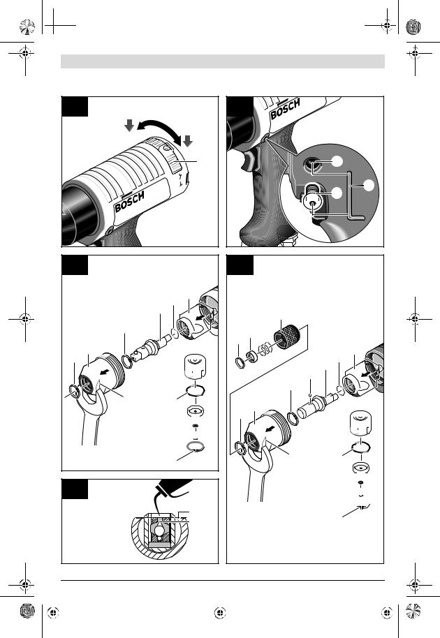
Aufhängevorrichtung (siehe Bild A)
Mit dem Aufhängebügel 14 können Sie das Druckluftwerkzeug an einer Aufhängevorrichtung befestigen.
–Setzen Sie den Aufhängebügel 14 auf das Druckluftwerkzeug auf, und lassen Sie ihn in die Schlitze 9 einrasten.
Je nach Schwerpunkt des Druckluftwerkzeugs können Sie entweder die vorderen oder hinteren Schlitze verwenden.
Bei einer Befestigung hinten am Druckluftwerkzeug müssen Sie den Abstandhalter 15 verwenden, um einen sicheren Sitz des Aufhängebügels 14 zu gewährleisten.
Kontrollieren Sie regelmäßig den Zustand des Aufhängebügels und der Haken in der Aufhängevorrichtung.
Einspannvorrichtung
–Im angegebenen Einspannbereich 11 können Sie das Druckluftwerkzeug in einer Einspannvorrichtung befestigen. Nutzen Sie möglichst den gesamten Einspannbereich. Je geringer der Einspannbereich, desto stärker wirken die Spannkräfte.
Zusatzgriff
–Schieben Sie den Zusatzgriff 12 auf den Einspannbereich
11.
Sie können den Zusatzgriff 12 beliebig schwenken, um eine sichere und ermüdungsarme Arbeitshaltung zu erreichen.
–Drehen Sie die Flügelschraube für die Zusatzgriffverstellung entgegen dem Uhrzeigersinn und schwenken Sie den Zusatzgriff 12 in die gewünschte Position. Danach drehen Sie die Flügelschraube im Uhrzeigersinn wieder fest.
Deutsch | 11
Abluftführung
Mit einer Abluftführung können Sie die Abluft durch einen Abluftschlauch von Ihrem Arbeitsplatz wegleiten und gleichzeitig eine optimale Schalldämpfung erreichen. Zudem verbessern Sie Ihre Arbeitsbedingungen, da Ihr Arbeitsplatz nicht mehr von ölhaltiger Luft verschmutzt werden kann oder Staub bzw. Späne aufgewirbelt werden.
Dezentrale Abluftführung (siehe Bild B)
–Schrauben Sie den Schalldämpfer am Luftaustritt 5 heraus, und ersetzen Sie ihn durch einen Schlauchnippel 6.
–Lockern Sie die Schlauchschelle 16 des Abluftschlauches 17, und befestigen Sie den Abluftschlauch über dem Schlauchnippel 6, indem Sie die Schlauchschelle fest anziehen.
Anschluss an die Luftversorgung
Achten Sie darauf, dass der Luftdruck nicht niedriger als 6,3 bar (91 psi) ist, da das Druckluftwerkzeug für diesen Betriebsdruck ausgelegt ist.
Für eine maximale Leistung müssen die Werte für die lichte Schlauchweite sowie die Anschlussgewinde, wie in der Tabelle „Technische Daten“ angegeben, eingehalten werden. Zur Erhaltung der vollen Leistung nur Schläuche bis maximal 4 m Länge verwenden.
Die zugeführte Druckluft muss frei von Fremdkörpern und Feuchtigkeit sein, um das Druckluftwerkzeug vor Beschädigung, Verschmutzung und Rostbildung zu schützen.
Hinweis: Die Verwendung einer Druckluft-Wartungseinheit ist notwendig. Diese gewährleistet eine einwandfreie Funktion der Druckluftwerkzeuge.
Beachten Sie die Betriebsanleitung der Wartungseinheit.
Sämtliche Armaturen, Verbindungsleitungen und Schläuche müssen dem Druck und der erforderlichen Luftmenge entsprechend ausgelegt sein.
Vermeiden Sie Verengungen der Zuleitungen, z.B. durch Quetschen, Knicken oder Zerren!
Prüfen Sie im Zweifelsfall den Druck am Lufteintritt mit einem Manometer bei eingeschaltetem Druckluftwerkzeug.
Anschluss der Luftversorgung an das Druckluftwerkzeug (siehe Bild C)
–Schrauben Sie einen Schlauchnippel 6 in den Anschlussstutzen am Lufteinlass 7 ein.
Um Beschädigungen an innen liegenden Ventilteilen des Druckluftwerkzeugs zu vermeiden, sollten Sie beim Einund Ausschrauben des Schlauchnippels 6 an dem vorstehenden Anschlussstutzen des Lufteinlasses 7 mit einem Gabelschlüssel (Schlüsselweite 22 mm) gegenhalten.
–Lockern Sie die Schlauchschellen 16des Zuluftschlauches 18, und befestigen Sie den Zuluftschlauch über dem Schlauchnippel 6, indem Sie die Schlauchschelle fest anziehen.
Hinweis: Befestigen Sie den Zuluftschlauch immer erst am Druckluftwerkzeug, dann an der Wartungseinheit.
|
Bosch Power Tools |
|
|
1 609 92A 37T | (14.9.16) |
|||
|
|
|
|
|
|
|
|
|
|
|
|
|
|
|
|
|
|
|
|
|
|
|
|

OBJ_BUCH-1993-004.book Page 12 Wednesday, September 14, 2016 9:08 AM
12 | Deutsch
Werkzeugwechsel beim Schraubkopf mit Außenvierkant (siehe Bild D)
(0 607 661 505/... 507/... 509)
Achten Sie beim Einsetzen eines Einsatzwerkzeugs darauf, dass es fest auf der Werkzeugaufnahme sitzt.
Wenn das Einsatzwerkzeug nicht fest mit der Werkzeugaufnahme verbunden ist, kann es sich wieder lösen und nicht mehr kontrolliert werden.
Einsatzwerkzeug einsetzen
–Drücken Sie den Stift am Vierkant der Werkzeugaufnahme 2, z.B. mit Hilfe eines schmalen Schraubendrehers, nach innen und schieben Sie das Einsatzwerkzeug 1 über den Vierkant. Achten Sie darauf, dass der Stift in die Aussparung des Einsatzwerkzeugs einrastet.
Einsatzwerkzeug entnehmen
–Drücken Sie den Stift in der Aussparung des Einsatzwerkzeugs 1 nach innen, und ziehen Sie das Einsatzwerkzeug von der Werkzeugaufnahme 2.
Werkzeugwechsel beim Schraubkopf mit Schnellwechselfutter (siehe Bild E)
(0 607 661 506/... 510)
Achten Sie beim Einsetzen eines Einsatzwerkzeugs darauf, dass der Schaft des Einsatzwerkzeugs fest in der Werkzeugaufnahme sitzt. Wenn der Schaft des Einsatzwerkzeugs nicht tief genug in die Werkzeugaufnahme gesteckt wird, kann sich das Einsatzwerkzeug wieder lösen und nicht mehr kontrolliert werden.
Einsatzwerkzeug einsetzen
Verwenden Sie nur Einsatzwerkzeuge mit passendem Einsteckende (siehe „Technische Daten“).
–Ziehen Sie die Hülse 13 des Schnellwechselfutters nach vorn.
–Stecken Sie das Einsatzwerkzeug 1 in die Werkzeugaufnahme 2 und lassen Sie die Hülse 13 wieder los.
Einsatzwerkzeug entnehmen
–Ziehen Sie die Hülse 13 des Schnellwechselfutters nach vorn.
–Nehmen Sie das Einsatzwerkzeug 1 aus der Werkzeugaufnahme 2 und lassen Sie die Hülse 13 wieder los.
Betrieb
Inbetriebnahme
Das Druckluftwerkzeug arbeitet optimal bei einem Arbeitsdruck von 6,3 bar (91 psi), gemessen am Lufteintritt bei eingeschaltetem Druckluftwerkzeug.
Drehrichtung einstellen (siehe Bild F)
Achten Sie auf die eingestellte Drehrichtung, bevor Sie das Druckluftwerkzeug einschalten. Wenn Sie beispielsweise eine Schraube lösen wollen und die Drehrichtung ist so eingestellt, dass die Schraube eingedreht wird, kann es zu einer heftigen unkontrollierten Bewegung des Druckluftwerkzeugs kommen.
Betätigen Sie den Schieber 10 für die Drehrichtung nur bei Stillstand des Druckluftwerkzeugs.
–Rechtslauf: Schieben Sie den Schieber 10 für die Drehrichtung nach rechts.
–Linkslauf: Schieben Sie den Schieber 10 für die Drehrichtung nach links.
Ein-/Ausschalten
Allgemeine Hinweise
Hinweis: Läuft das Druckluftwerkzeug, z.B. nach längerer Ruhezeit, nicht an, unterbrechen Sie die Luftversorgung, und drehen Sie an der Werkzeugaufnahme 2 den Motor mehrmals durch. Dadurch werden Adhäsionskräfte beseitigt.
Um Energie zu sparen, schalten Sie das Druckluftwerkzeug nur ein, wenn Sie es benutzen.
Ein-/Ausschalten
Die Druckluftwerkzeuge haben ein vom Drehmoment abhängiges Impulswerk mit Abschaltung, das in weitem Bereich einstellbar ist. Es spricht an, wenn das eingestellte Drehmoment erreicht ist.
–Zum Einschalten des Elektrowerkzeugs drücken Sie den Ein-/Ausschalter 4 bis zum Anschlag.
–Das Elektrowerkzeug schaltet sich automatisch aus, sobald das eingestellte Drehmoment erreicht ist.
–Bevor Sie das Druckluftwerkzeug für einen neuen Schraubvorgang erneut einschalten können, müssen Sie den Ein-/ Ausschalter 4 erst wieder loslassen.
Bei vorzeitigem Loslassen des Ein-/Ausschalters 4 wird das voreingestellte Drehmoment nicht erreicht.
Hinweis: Schaltet das Druckluftwerkzeug nicht automatisch ab, müssen Sie das Drehmoment neu einstellen (siehe „Drehmoment einstellen“, Seite 12).
Drehmoment einstellen (siehe Bild G)
Das Drehmoment wird stoßweise erzeugt. Der Impuls wird in einem Impulswerk erzeugt, indem eine Ölmenge durch eine einstellbare Engstelle gepresst wird.
Das Drehmoment kann von außen eingestellt werden.
–Drehen Sie die Verschlussschraube 8 mit dem mitgelieferten Innensechskantschlüssel 19 heraus.
In der Öffnung befindet sich die Einstellschraube 20 fürs Drehmoment.
–Verdrehen Sie die Einstellschraube 20 mit Hilfe des Innensechskantschlüssels 19.
Drehen im Uhrzeigersinn ergibt ein höheres Drehmoment, Drehen gegen den Uhrzeigersinn ein niedrigeres Drehmoment.
Hinweis: Die erforderliche Drehmoment-Einstellung ist von der Art der Schraubverbindung abhängig und lässt sich am Besten im praktischen Versuch ermitteln.
–Überprüfen Sie eine Probeverschraubung mit einem Drehmomentschlüssel.
Wird der gewünschte Wert nicht erreicht, wiederholen Sie die Einstellung des Drehmoments.
–Drehen Sie nach der Einstellung die Verschlussschraube 8 wieder ein.
|
1 609 92A 37T | (14.9.16) |
|
|
Bosch Power Tools |
|||
|
|
|
|
|
|
|
|
|
|
|
|
|
|
|
|
|
|
|
|
|
|
|
|
OBJ_BUCH-1993-004.book Page 13 Wednesday, September 14, 2016 9:08 AM
Hinweis: Schaltet das Druckluftwerkzeug beim Erreichen des eingestellten Drehmoments nicht automatisch ab, müssen Sie die Einstellschraube 20 gegen den Uhrzeigersinn drehen, um das Anziehdrehmoment zu verringern.
Arbeitshinweise
Plötzlich auftretende Belastungen bewirken einen starken Drehzahlabfall oder den Stillstand, schaden aber nicht dem Motor.
Wartung und Service
Wartung und Reinigung
Lassen Sie Wartungsund Reparaturarbeiten nur von qualifiziertem Fachpersonal durchführen. Damit wird sichergestellt, dass die Sicherheit des Druckluftwerkzeugs erhalten bleibt.
Eine autorisierte Bosch-Kundendienststelle führt diese Arbeiten schnell und zuverlässig aus.
Verwenden Sie ausschließlich Bosch Original-Ersatzteile.
Druckluftwerkzeug schmieren
Zur Direktschmierung des Druckluftwerkzeugs oder zur Beimischung an der Wartungseinheit sollten Sie Motorenöl SAE 10 oder SAE 20 verwenden.
Regelmäßige Reinigung
–Reinigen Sie regelmäßig das Sieb am Lufteinlass des Druckluftwerkzeugs. Schrauben Sie dazu den Schlauchnippel 6 ab und entfernen Sie Staubund Schmutzpartikel vom Sieb. Schrauben Sie anschließend den Schlauchnippel wieder fest.
–In der Druckluft enthaltene Wasserund Schmutzpartikel verursachen Rostbildung und führen zum Verschleiß von Lamellen, Ventilen etc. Um dies zu verhindern, sollten Sie am Lufteinlass 7 einige Tropfen Motorenöl einfüllen.
Schließen Sie das Druckluftwerkzeug wieder an die Luftversorgung an (siehe „Anschluss an die Luftversorgung“, Seite 11) und lassen Sie es 5 –10 s laufen, während Sie das auslaufende Öl mit einem Tuch aufsaugen. Wird das
Druckluftwerkzeug längere Zeit nicht benötigt, sollten Sie dieses Verfahren immer durchführen.
Turnusmäßige Wartung
–Siehe auch „Ölwechsel“, Seite 13.
–Reinigen Sie nach den ersten 150 Betriebsstunden das Getriebe mit einem milden Lösungsmittel. Befolgen Sie die Hinweise des Lösungsmittelherstellers zu Gebrauch und Entsorgung. Schmieren Sie das Getriebe anschließend mit Bosch-Spezial-Getriebefett. Wiederholen Sie den Reinigungsvorgang jeweils nach 300 Betriebsstunden ab der ersten Reinigung.
Spezial-Getriebefett (225 ml) Sachnummer 3 605 430 009
–Die Motorlamellen sollten turnusmäßig von Fachpersonal überprüft und gegebenenfalls ausgetauscht werden.
–Überprüfen Sie nach jeder Wartung die Drehzahl mit Hilfe eines Drehzahlmessgerätes und prüfen Sie das Druckluftwerkzeug auf erhöhte Vibrationen.
Deutsch | 13
Ölwechsel
Nach ca. 150000 Verschraubungen im harten Schraubfall (max. 2 –3 Impulse) sind das Öl im Impulswerk 26 sowie die Dichtringe 25, 29 und 31 zu wechseln.
Ausschließlich zu verwendendes Zubehör
|
0 607 661 ... |
... 505 |
|
|
|
... 506 |
|
|
|
... 509 |
|
|
|
... 510 |
... 507 |
Hydrauliköl |
3 605 430 008 |
|
|
Dichtringsatz (7 Stck.) |
3 607 030 360 |
|
– |
Dichtringsatz (7 Stck.) |
3 607 030 352 |
– |
|
Sie benötigen aus dem Dichtringsatz nur 3 Gummringe. Achten Sie bei den zu ersetzenden Dichtringen genau auf die passende Größe.
Demontage des Impulswerks (siehe Bild H bzw. Bild I)
Um das Öl zu wechseln, muss das Impulswerk 26 ausgebaut werden.
Lassen Sie das Impulswerk vor dem Ausbau auf Raumtemperatur abkühlen.
Tragen Sie beim Wechsel des Öls geeignete Schutzkleidung, Schutzbrille und Schutzhandschuhe.
–Setzen Sie mit einem passenden Gabelschlüssel (Schlüsselweite siehe „Technische Daten“) an der Schlüsselfläche 34 an und schrauben Sie das Gehäuse 3 mit dem Impulswerk gegen den Uhrzeigersinn heraus.
Achten Sie darauf, dass der Lamellenmotor nicht aus dem hinteren Druckluftwerkzeug-Gehäuse fällt.
–0 607 661 505/... 507/... 509:
Entfernen Sie den Sicherungsring 21 am Gehäuse 3 und schieben Sie das Impulswerk aus dem Gehäuse.
0 607 661 506/... 510:
Entfernen Sie den Sicherungsring 35 am Schnellwechselfutter.
Ziehen Sie den Stahlring 36, die Druckfeder 37 und die Hülse 13 ab.
Entfernen Sie den Sicherungsring 21 am Gehäuse 3 und schieben Sie das Impulswerk aus dem Gehäuse.
Achten Sie auf eine kleine Kugel 23, die Ihnen entgegenfallen kann.
–Spannen Sie das Impulswerk in einen Schraubstock ein und achten Sie darauf, dass der Kolbendeckel 30 nach oben zeigt.
–Drehen Sie die Befestigungsschraube 32 mit einem Innensechskantschlüssel (2,5 mm) heraus, während Sie am Kolbendeckel 30 mit einem passenden Gabelschlüssel (Schlüsselweite siehe „Technische Daten“) gegenhalten.
–Entfernen Sie den Sicherungsring 33 und nehmen Sie den Kolbendeckel 30 ab.
–Spannen Sie das Impulswerk 26 aus dem Schraubstock aus und entleeren Sie das Öl.
Entsorgen Sie das Altöl umweltgerecht.
–Entfernen Sie den Sicherungsring 22 und entnehmen Sie die Nockenwelle 24.
|
Bosch Power Tools |
|
|
1 609 92A 37T | (14.9.16) |
|||
|
|
|
|
|
|
|
|
|
|
|
|
|
|
|
|
|
|
|
|
|
|
|
|

OBJ_BUCH-1993-004.book Page 14 Wednesday, September 14, 2016 9:08 AM
14 | Deutsch
–Entfernen Sie den Kolben 28, indem Sie das Impulswerk mit der Öffnung nach unten leicht aufklopfen.
–Prüfen Sie die Teile des Impulswerks auf Verschleißspuren.
–Bereiten Sie die neuen Dichtringe 25, 29 und 31 zur Montage vor, indem Sie sie mit Hydrauliköl bestreichen.
Montage des Impulswerks
–Kontrollieren Sie den Sicherungsring 27 am Kolben auf korrekten Sitz.
–Setzen Sie einen neuen Dichtring 25 an der Nockenwelle 24 und einen neuen Dichtring 29 am Impulswerk 26 ein.
–Setzen Sie den Kolben 28 mit dem Sicherungsring 27 nach unten in das Impulswerk 26 ein.
–Schieben Sie die Nockenwelle 24 von vorn mit leichtem Druck in den Kolben im Impulswerk.
–Montieren Sie den Sicherungsring 22 und kontrollieren Sie ihn auf korrekten Sitz.
–Spannen Sie das Impulswerk 26 mit der Öffnung nach oben in den Schraubstock ein.
–Drehen Sie die Nockenwelle 24 bis zum oberen Totpunkt.
–0 607 661 505/... 506/... 509/... 510:
Füllen Sie Hydrauliköl bis zum Rand des Impulswerks ein. Drehen Sie die Nockenwelle 24 langsam, fünf bis sechs Mal, durch.
Wenn keine Luftblasen mehr aufsteigen, drehen Sie die Nockenwelle bis zum oberen Totpunkt und füllen Sie erneut Hydrauliköl bis zum Rand des Impulswerks ein.
Achten Sie darauf, dass das Hydrauliköl immer bis zum oberen Rand des Impulswerks und nicht nur bis zum oberen Kolbenrand aufgefüllt wird!
Wiederholen Sie den Vorgang bis sich keine Luft mehr im Kolben befindet.
Setzen Sie den Kolbendeckel 30 mit leichter Drehung auf und drücken Sie ihn mit einem weichen Tuch nach unten. Entfernen Sie das Restöl.
–0 607 661 507:
Füllen Sie Hydrauliköl bis zum oberen Kolbenrand 38 ein (siehe Bild J).
Drehen Sie die Nockenwelle 24 langsam, fünf bis sechs Mal, durch.
Wenn keine Luftblasen mehr aufsteigen, drehen Sie die Nockenwelle bis zum oberen Totpunkt und füllen Sie erneut Hydrauliköl bis zum oberen Kolbenrand 38 ein.
Achten Sie darauf, dass das Hydrauliköl nur bis zum oberen Kolbenrand und nie bis zum Rand des Impulswerks aufgefüllt wird! Das Druckluftwerkzeug bringt nicht die volle Leistung, wenn zu viel Öl eingefüllt wurde. Wiederholen Sie den Vorgang bis sich keine Luft mehr im Kolben befindet.
Setzen Sie den Kolbendeckel 30 mit leichter Drehung auf und drücken Sie ihn mit einem weichen Tuch nach unten. Sollte dabei Hydrauliköl austreten, haben Sie zu viel Öl eingefüllt.
–Setzen Sie einen neuen Dichtring 31 am Kolbendeckel 30 ein und drehen Sie die Befestigungsschraube 32 mit einem Innensechskantschlüssel (2,5 mm) ein.
–Setzen Sie den Sicherungsring 33 ein und achten Sie darauf, dass er in die Nut einrastet.
–Ziehen Sie die Befestigungsschraube 32 mit einem Drehmoment von 1,5±0,4 Nm fest, während Sie am Kolbendeckel 30 mit einem passenden Gabelschlüssel (Schlüsselweite siehe „Technische Daten“) gegenhalten.
–Spannen Sie das Impulswerk 26 aus dem Schraubstock aus und drehen Sie die Nockenwelle 24 einmal durch.
–Setzen Sie das Impulswerk 26 in das Gehäuse 3 ein.
–Montieren Sie den Sicherungsring 21 am Gehäuse.
–Setzen Sie mit einem passenden Gabelschlüssel (Schlüsselweite siehe „Technische Daten“) an der Schlüsselfläche 34 an und schrauben Sie das Gehäuse 3 mit dem Impulswerk im Uhrzeigersinn mit 35±5 Nm wieder fest.
–0 607 661 506/... 510:
Legen Sie die Kugel 23 in die Öffnung an der Nockenwelle
24.
Ziehen Sie die Hülse 13 auf der Nockenwelle über die Kugel, setzen Sie die Druckfeder 37 und den Stahlring 36 wieder auf und montieren Sie den Sicherungsring 35 am Schnellwechselfutter.
Achten Sie darauf, dass der Sicherungsring 35 in der Nut sitzt und sich die Hülse 13 des Schnellwechselfutters leicht bewegen lässt.
Überprüfen Sie nach jedem Ölwechsel die einwandfreie Funktion des Druckluftwerkzeugs.
Zubehör
Über das komplette Qualitätszubehörprogramm können Sie sich im Internet unter www.bosch-pt.com oder bei Ihrem Fachhändler informieren.
Kundendienst und Anwendungsberatung
Geben Sie bei allen Rückfragen und Ersatzteilbestellungen bitte unbedingt die 10-stellige Sachnummer laut Typenschild des Druckluftwerkzeugs an.
Der Kundendienst beantwortet Ihre Fragen zu Reparatur und Wartung Ihres Produkts sowie zu Ersatzteilen. Explosionszeichnungen und Informationen zu Ersatzteilen finden Sie auch unter:
www.bosch-pt.com
Das Bosch-Anwendungsberatungs-Team hilft Ihnen gerne bei Fragen zu unseren Produkten und deren Zubehör.
www.powertool-portal.de, das Internetportal für Handwerker und Heimwerker.
|
1 609 92A 37T | (14.9.16) |
|
|
Bosch Power Tools |
|||
|
|
|
|
|
|
|
|
|
|
|
|
|
|
|
|
|
|
|
|
|
|
|
|

OBJ_BUCH-1993-004.book Page 15 Wednesday, September 14, 2016 9:08 AM
Deutsch | 15
Deutschland
Robert Bosch Power Tools GmbH
Servicezentrum Elektrowerkzeuge Zur Luhne 2
37589 Kalefeld – Willershausen
Unter www.bosch-pt.com können Sie online Ersatzteile bestellen oder Reparaturen anmelden.
Kundendienst: Tel.: (0711) 40040480 Fax: (0711) 40040481
E-Mail: Servicezentrum.Elektrowerkzeuge@de.bosch.com Anwendungsberatung: Tel.: (0711) 40040480
Fax: (0711) 40040482
E-Mail: Anwendungsberatung.pt@de.bosch.com
Österreich
Unter www.bosch-pt.at können Sie online Ersatzteile bestellen.
Tel.: (01) 797222010
Fax: (01) 797222011
E-Mail: service.elektrowerkzeuge@at.bosch.com
Schweiz
Unter www.bosch-pt.com/ch/de können Sie online Ersatzteile bestellen.
Tel.: (044) 8471511
Fax: (044) 8471551
E-Mail: Aftersales.Service@de.bosch.com
Luxemburg
Tel.: +32 2 588 0589
Fax: +32 2 588 0595
E-Mail: outillage.gereedschap@be.bosch.com
Entsorgung
Druckluftwerkzeug, Zubehör und Verpackung sollten einer umweltgerechten Wiederverwertung zugeführt werden.
Entsorgen Sie Schmierund Reinigungsstoffe umweltgerecht. Beachten Sie die gesetzlichen Vorschriften.
Entsorgen Sie die Motorlamellen sachgemäß! Motorlamellen enthalten Teflon. Erhitzen Sie sie nicht über
400 °C, da sonst gesundheitsschädliche Dämpfe entstehen können.
Wenn Ihr Druckluftwerkzeug nicht mehr gebrauchsfähig ist, geben Sie es bitte beim Handel ab oder schicken es direkt (bitte ausreichend frankiert) an:
Recyclingzentrum Elektrowerkzeuge Osteroder Landstr. 3
37589 Kalefeld
Änderungen vorbehalten.
|
Bosch Power Tools |
|
|
1 609 92A 37T | (14.9.16) |
|||
|
|
|
|
|
|
|
|
|
|
|
|
|
|
|
|
|
|
|
|
|
|
|
|
OBJ_BUCH-1993-004.book Page 16 Wednesday, September 14, 2016 9:08 AM
16 | English
English
Safety Notes
General Safety Rules for Pneumatic Tools
WARNING |
Before installing, operating, repairing, |
|
maintaining and replacing accessories |
as well as prior to working near by the pneumatic tool, please read and observe all instructions. Failure to follow the following safety warnings may result in serious injury.
Save all safety warnings and instructions for future reference, and make them available to the operator.
Work area safety
Pay attention to surfaces that may have become slippery from using the machine, and to tripping hazards from the pneumatic or hydraulic hose. Slipping, tripping and falling are main reasons for workplace injuries.
Do not operate the pneumatic tool in explosive atmospheres, such as in the presence of flammable liquids, gases or dusts. While working the workpiece, sparks can be created which may ignite the dust or fumes.
Keep children and bystanders away from your workplace while operating the pneumatic tool. Distractions from other persons can cause you to lose control over the pneumatic tool.
Pneumatic tool safety
Never direct the airflow against yourself or other persons close by, and conduct cold air away from your hands. Compressed air can lead to serious injuries.
Check the connections and the air supply lines. All maintenance units, couplers, and hoses should conform to the product specifications in terms of pressure and air volume. Too low pressure impairs the function of the pneumatic tool; too high pressure can result in material damage and personal injury.
Protect the hoses from kinks, restrictions, solvents, and sharp edges. Keep the hoses away from heat, oil, and rotating parts. Immediately replace a damaged hose. A defective air supply line may result in a wild com- pressed-air hose and can cause personal injury. Raised dust or chips may cause serious eye injury.
Make sure that hose clamps are always tightened firmly. Loose or damaged hose clamps may result in uncontrolled air escape.
Personal safety
Stay alert, watch what you are doing, and use common sense when operating a pneumatic tool. Do not use a pneumatic tool while tired or under the influence of drugs, alcohol, or medication. A moment of inattention while operating a pneumatic tool may result in personal injury.
Use personal protective equipment. Always wear eye protection. Wearing personal protective equipment – such as a respirator, non-skid safety shoes, hard hat or
hearing protection – according to the instructions of your employer or as required by the provisions for work and health protection, reduces the risk of personal injury.
Prevent unintentional starting. Make sure that the pneumatic tool is switched off before connecting it to the air supply, picking it up or carrying it. When your finger is on the On/Off switch while carrying the pneumatic tool or when connecting the pneumatic tool to the air supply while it is switched on, accidents can occur.
Remove any adjustment tools before switching on the pneumatic tool. A wrench or key left attached to a rotating part of a pneumatic tool may result in personal injury.
Do not overreach. Keep proper footing and balance at all times. This enables better control of the pneumatic tool in unexpected situations.
Dress properly. Do not wear loose clothing or jewellery. Keep your hair, clothing and gloves away from moving parts. Loose clothes, jewellery or long hair can be caught in moving parts.
Do not directly inhale the exhaust air. Avoid exposing the eyes to exhaust air. The pneumatic tool’s exhaust air can contain water, oil, metal particles and debris from the compressor. This can cause damage to one’s health.
Pneumatic tool use and care
Use the clamping devices or a vice to secure and support the workpiece. Holding the workpiece by hand or against your body will not allow for safe operation of the pneumatic tool.
Do not overload the pneumatic tool. Use the pneumatic tool intended for your work. The correct pneumatic tool will do the job better and safer at the rate for which it is designed.
Do not use a pneumatic tool that has a defective On/Off switch. A pneumatic tool that cannot be controlled with the switch is dangerous and must be repaired.
Disconnect the air supply before making any adjustments, changing accessories, or when not using for extended periods. This safety measure prevents accidental starting of the pneumatic tool.
Store idle pneumatic tools out of the reach of children. Do not allow persons unfamiliar with the pneumatic tool or these instructions to operate the device. Pneumatic tools are dangerous in the hands of untrained users.
Maintain the pneumatic tool with care. Check for misalignment or binding of moving parts, breakage of parts and any other condition that may affect the pneumatic tool’s operation. Have damaged parts repaired before using the pneumatic tool. Many accidents are caused by poorly maintained pneumatic tools.
Use the pneumatic tool, accessories, application tools, etc. according to these instructions. Take into consideration the working conditions and the activities to be carried out. This reduces the development of dust, vibrations and noise to the greatest extent.
The pneumatic tool should be set up, adjusted or used exclusively by qualified and trained operators.
|
1 609 92A 37T | (14.9.16) |
|
|
Bosch Power Tools |
|||
|
|
|
|
|
|
|
|
|
|
|
|
|
|
|
|
|
|
|
|
|
|
|
|

OBJ_BUCH-1993-004.book Page 17 Wednesday, September 14, 2016 9:08 AM
The pneumatic tool may not be modified in any way.
Modifications can reduce the effectivity of the safety measures and increase the risks for the operator.
Service
Have your pneumatic tool repaired only through a qualified repair person and only using original replacement parts. This will ensure that the safety of the pneumatic tool is maintained.
Safety Warnings for Pneumatic Impulse Screwdrivers
Check if the type plate can be read. If required, provide for replacement from the manufacturer.
In case of breakage of the workpiece or an accessory, or even of the pneumatic tool itself, parts can be thrown about at high speed.
During operation, repairs or maintenance, and when replacing accessories on the pneumatic tool, always wear shock-resistant eye protection. The degree of the required protection should be separately evaluated for each individual application.
Never switch the pneumatic tool on while carrying it.
Clothing or hair can be caught in a rotating tool holder and lead to injuries.
Wear close-fitting gloves. The flow of compressed air makes the handles of pneumatic tools cold. Warm hands are less sensitive to vibrations. Loose fitting gloves can be caught by rotating parts.
Keep your hands away from the socket drive and the rotating application tool. Never hold a rotating application tool or the drive. You could injure yourself.
Be careful when working conditions are tight. Danger of injury from pinched or caught fingers due to reaction torque.
The operators and the maintenance personnel must be physically capable to handle the size, weight and power of the pneumatic tool.
Be prepared for unexpected movements of the pneumatic tool that can develop owing to reaction forces or breakage of the application tool. Maintain a firm grip on the pneumatic tool and position your body and arms to allow you to resist such movements. These precautions can prevent injuries.
Use auxiliary aids to absorb reaction torque, such as a supporting fixture. If this is not possible, use an auxiliary handle.
In case of an interruption of the air supply or reduced operating pressure, switch the pneumatic tool off.
Check the operating pressure and start again when the operating pressure is optimal.
When using the pneumatic tool for the performance of work-related activities, the operator may experience unpleasant sensations in the hands, arms, shoulders, neck area or other body parts.
When working with this pneumatic tool, assume a comfortable stance, hold the tool securely and avoid unfa-
English | 17
vourable positions or such positions, where it is difficult to keep your balance. For prolonged work, the operator should change the stance or posture, which can help avoid discomfort and fatigue.
Should the operator perceive symptoms such as persistent nausea, discomfort, throbbing, pain, tingling, numbness, burning or stiffness, these warning signs should not be ignored. The operator should notify his employer about the symptoms and consult a qualified physician.
Do not touch any socket drives or accessories during the impact procedure, as this may increase the risk of cutting, burning or injuries caused by vibrations.
Only use impact sockets in good working condition. A defective condition of hand sockets and accessories can cause them to shatter and be ejected when used with impactor impulse screwdrivers.
Avoid contact with “live” conductors. The pneumatic tool is not insulated; contact with a “live” conductor can lead to an electric shock.
WARNING |
The dust developing during sanding, |
|
sawing, grinding, drilling and similar |
operations can act carcinogenic, teratogenic or mutagenic. Some of the substances contained in these dusts are:
–Lead in lead-based paints and varnishes;
–Crystalline silica in bricks, cement and other masonry work;
–Arsenic and chromate in chemically treated wood.
The risk of disease depends on how often you are exposed to these substances. To reduce the risk, you should work only in well ventilated rooms with appropriate protective equipment (e. g. with specially designed respirators that filter out even the smallest dust particles).
Wear ear protectors. Exposure to noise can cause hearing loss.
When working on the workpiece, additional noise can develop, which can be avoided through appropriate measures (e. g. by using damping materials on occurrence of ringing noise from the workpiece).
When the pneumatic tool is equipped with a silencer, always ensure that it is available and in proper working condition when operating the pneumatic tool.
Vibration effects may cause damage to the nerves and blood circulation disorders in the hands and arms.
If you notice that the skin of your fingers or hands becomes numb, tingles, hurts or turns white, stop working with the pneumatic tool, notify your employer and consult a physician.
Do not use worn or poorly fitting socket drives and extensions. This can lead to intensification of vibrations.
If possible, use a stand, spring pull/balancer or compensation device in order to support the weight of the pneumatic tool.
Hold the pneumatic tool with a not too firm yet secure grip, compliant with the required hand-reaction forces.
The vibrations can be intensified the firmer you hold the tool.
|
Bosch Power Tools |
|
|
1 609 92A 37T | (14.9.16) |
|||
|
|
|
|
|
|
|
|
|
|
|
|
|
|
|
|
|
|
|
|
|
|
|
|

OBJ_BUCH-1993-004.book Page 18 Wednesday, September 14, 2016 9:08 AM
18 | English
When universal rotary couplings (bayonet couplings) are being used, retaining pins are required. Use Whipcheck hose restraints to protect against failed hose connections or the connection between hose and pneumatic tool.
Never carry the pneumatic tool by the hose.
If you want to operate the pneumatic tool in a suspension device or a clamping fixture, take care to fasten it in the device/fixture first before connecting it to the air supply. This measure prevents accidental starting of operation.
Symbols
The following symbols could have a meaning for the use of your pneumatic tool. Please take note of the symbols and their meaning. The correct interpretation of the symbols will help you to use the pneumatic tool in a better and safer manner.
Symbol Meaning
Before installing, operating, repairing, maintaining and replacing accessories as well as prior to working near by the pneumatic tool, please read and observe all instructions. Failure to follow the following safety warnings and instructions may result in serious injury.
Wear safety goggles.
W |
Watt |
Power output |
|
Nm |
Newton metre |
Unit of energy |
|
(torque) |
|||
|
|
||
kg |
Kilogram |
Mass, weight |
|
lbs |
Pounds |
||
|
|||
|
|
|
|
mm |
Millimetre |
Length |
|
min |
Minutes |
Time period, |
|
s |
Seconds |
duration |
|
min-1 |
Revolutions or motions per |
No-load speed |
|
|
minute |
|
|
bar |
bar |
Air pressure |
|
psi |
pounds per square inch |
||
|
|||
|
|
|
|
l/s |
Litres per second |
Air consumption |
|
cfm |
cubic feet/minute |
||
|
|||
dB |
Decibel |
Unit of relative |
|
loudness |
|||
|
|
Symbol |
Meaning |
|
|||
QC |
Quick-change chuck |
|
|||
|
|
|
Symbol for hexagon socket |
|
|
|
Symbol for external drive |
Tool holder |
|||
|
|
|
US fine thread |
||
|
|
|
|
||
UNF |
(Unified National Fine |
|
|||
|
|
|
Thread Series) |
|
|
G |
Whitworth thread |
Connecting thread |
|||
NPT |
National pipe thread |
||||
|
|||||
|
|
|
|
|
|
|
|
|
Right rotation |
|
|
|
|
|
|
||
R |
Rotational direction |
||||
|
|||||
|
|
|
Left rotation |
||
|
|
|
|
||
L |
|
||||
|
|
||||
Product Description and Specifications
Read all safety warnings and all instructions. Failure to follow the warnings and instructions may result in electric shock, fire and/or serious injury.
While reading the operating instructions, unfold the fold-out page with the illustration of the pneumatic tool and leave it open.
Intended Use
The pneumatic tool is intended for driving in and loosening screws as well as for tightening and loosening nuts within the given dimension and power range.
Product Features
The numbering of the product features refers to the illustrations on the graphics page. The illustrations are partly schematic and may differ from your pneumatic tool.
1 Tool bit
2 Tool holder
3 Housing with impulse mechanism
4 On/Off switch
5 Air outlet with silencer
6 Hose fitting
7 Connection socket at air intake
8 Locking screw
9 Fastening slots for utility clip
10Switch for direction of rotation (right / left rotation)
11Clamping area (collar)(e. g. for an auxiliary handle)
12Auxiliary handle*
13Sleeve of the quick-change chuck
14Utility clip
15Spacer block
16Hose clamp
17Exhaust-air hose
|
1 609 92A 37T | (14.9.16) |
|
|
Bosch Power Tools |
|||
|
|
|
|
|
|
|
|
|
|
|
|
|
|
|
|
|
|
|
|
|
|
|
|
OBJ_BUCH-1993-004.book Page 19 Wednesday, September 14, 2016 9:08 AM
English | 19
18 |
Supply-air hose |
|
30 Piston cover |
|
|
|
|
|||
19 |
Allen key |
|
31 O-ring piston cover |
|
|
|
|
|||
20 |
Adjustment screw torque |
|
32 Fastening screw piston cover |
|
|
|||||
21 |
Retaining ring housing |
|
33 Retaining ring piston cover |
|
|
|||||
22 |
Retaining ring camshaft |
|
34 Spanner flat on housing |
|
|
|||||
23 |
Ball |
|
35 Retaining ring quick-change chuck |
|
|
|||||
24 |
Camshaft |
|
36 Steel ring |
|
|
|
|
|||
25 |
O-ring camshaft |
|
37 Pressure spring |
|
|
|
|
|||
26 |
Impulse mechanism |
|
38 Upper edge of piston |
|
|
|
|
|||
27 |
Retaining ring piston |
|
*Accessories shown or described are not part of the standard de- |
|||||||
28 |
Piston |
|
livery scope of the product. A complete overview of accessories |
|||||||
29 |
O-ring piston |
|
can be found in our accessories program. |
|
|
|||||
|
|
|
|
|
|
|
|
|
||
Technical Data |
|
|
|
|
|
|
|
|
|
|
|
|
|
|
|
|
|
|
|
|
|
Pneumatic Impulse Screwdriver |
|
0 607 661 ... |
|
|
|
|
|
|
||
Article number |
|
... 505 |
|
... 506 |
|
... 507 |
|
... 509 |
... 510 |
|
No-load speed |
min-1 |
4500 |
|
4500 |
|
4700 |
|
4000 |
4000 |
|
Output power |
W |
400 |
|
400 |
|
400 |
|
400 |
400 |
|
Maximum torque, hard screwdriving application |
|
|
|
|
|
|
|
|
|
|
according to ISO 5393 |
Nm |
16 –35 |
|
16 –35 |
|
28 –60 |
|
8 –18 |
8 –18 |
|
Max. torque for soft screwdriving application |
|
|
|
|
|
|
|
|
|
|
according to ISO 5393 |
Nm |
12 –29 |
|
12 –29 |
|
16 –47 |
|
5 –15 |
5 –15 |
|
Max. screw diameter |
mm |
M 8 |
|
M 8 |
|
M 10 |
|
M 6 |
M 6 |
|
Right/left rotation |
|
|
|
|
|
|
|
|
|
|
Tool holder |
|
3/8" |
|
– |
|
1/2" |
|
3/8" |
– |
|
– External square |
|
|
|
|
||||||
– Quick-change chuck |
|
– |
|
1/4" |
|
– |
|
– |
1/4" |
|
Spanner flat 34 on housing 3 |
mm |
32 |
|
32 |
|
40 |
|
32 |
32 |
|
Spanner flat on piston cover 30 |
mm |
11 |
|
11 |
|
15 |
|
11 |
11 |
|
Max. working pressure for tool |
bar |
6.3 |
|
6.3 |
|
6.3 |
|
6.3 |
6.3 |
|
|
|
psi |
91 |
|
91 |
|
91 |
|
91 |
91 |
Thread size of hose connection |
|
G 1/4" |
|
G 1/4" |
|
G 1/4" |
|
G 1/4" |
G 1/4" |
|
Inner diameter of hose |
mm |
9 |
|
9 |
|
9 |
|
6 |
6 |
|
Air consumption at no-load |
l/s |
16 |
|
16 |
|
17 |
|
16 |
16 |
|
|
|
cfm |
33.9 |
|
33.9 |
|
36.0 |
|
33.9 |
33.9 |
Weight according to EPTA-Procedure 01:2014 |
kg |
1.1 |
|
1.1 |
|
1.3 |
|
1.1 |
1.2 |
|
|
|
lbs |
2.4 |
|
2.4 |
|
2.9 |
|
2.4 |
2.6 |
Noise/Vibration Information |
|
|
|
|
|
|
|
|
|
|
Article number |
|
... 505 |
|
... 506 |
|
... 507 |
|
... 509 |
... 510 |
|
Measured sound values determined according to EN |
ISO 15744. |
|
|
|
|
|
|
|||
Typically the A-weighted noise level of the |
|
|
|
|
|
|
|
|
|
|
pneumatic tool is: |
|
|
|
|
|
|
|
|
|
|
Sound pressure level LpA |
dB(A) |
77 |
|
77 |
|
82 |
|
77 |
77 |
|
Sound power level LwA |
dB(A) |
88 |
|
88 |
|
93 |
|
88 |
88 |
|
Uncertainty k |
dB |
3 |
|
3 |
|
3 |
|
3 |
3 |
|
Wear hearing protection!
Vibration total values ah (triax vector sum) and uncertainty K determined according to EN 28927:
|
|
Screws: |
|
m/s2 |
|
|
|
|
|
|
|
|
|
|
|
|
|
a |
|
< 2.5 |
< 2.5 |
< 2.5 |
< 2.5 |
< 2.5 |
|
|
|||||
|
|
h |
|
m/s2 |
1.5 |
1.5 |
1.5 |
1.5 |
1.5 |
|
|
||||
|
|
K |
|
|
|
||||||||||
|
|
|
|
|
|
|
|
|
|
|
|
|
|
|
|
|
|
Bosch Power Tools |
|
|
|
|
|
|
|
1 609 92A 37T | (14.9.16) |
|
|
|||
|
|
|
|
|
|
|
|
|
|
|
|
|
|
|
|
|
|
|
|
|
|
|
|
|
|
|
|
|
|
|
|
|
|
|
|
|
|
|
|
|
|
|
|
|
|
|
|

OBJ_BUCH-1993-004.book Page 20 Wednesday, September 14, 2016 9:08 AM
20 | English
The vibration emission level given in this information sheet has been measured in accordance with a standardised test given in EN ISO 11148 and may be used to compare one pneumatic tool with another. It may be used for a preliminary assessment of exposure.
The declared vibration emission level represents the main applications of the pneumatic tool. However if the pneumatic tool is used for different applications, with different accessories or insertion tools or is poorly maintained, the vibration emission may differ. This may significantly increase the exposure level over the total working period.
An exact estimation of the level of exposure to vibration should also take into account the times when the pneumatic tool is switched off or when it is running but not actually doing the job. This may significantly reduce the exposure level over the total working period.
Identify additional safety measures to protect the operator from the effects of vibration such as: maintaining the pneumatic tool and the accessories, keeping the hands warm, organisation of work patterns.
These pneumatic tools belong to the CLEAN product line.
Through its oil-free operation and reduced air and energy consumption, Bosch’s CLEAN technology is operator-ergonomic and helps save the environment.
Operation with air containing oil is also possible.
consumption optimized |
– C |
|
lubrication-free |
– |
L |
ergonomic |
– E |
|
air tool |
– |
A |
noise reduction |
– |
N |
Declaration of Conformity
We declare under our sole responsibility that the product described under “Technical Data” is in conformity with the following standards or standardization documents:
EN ISO 11148 according to the provisions of the directive 2006/42/EC.
Technical file (2006/42/EC) at:
Robert Bosch Power Tools GmbH, PT/ECS, 70538 Stuttgart, GERMANY
Henk Becker |
Helmut Heinzelmann |
Executive Vice President |
Head of Product Certification |
Engineering |
PT/ECS |
Robert Bosch Power Tools GmbH
70538 Stuttgart, GERMANY
Stuttgart, 01.01.2017
Assembly
Devices for Safe Handling
If you want to operate the pneumatic tool in a suspension device or a clamping fixture, take care to fasten it in the device/fixture first before connecting it to the air supply. This measure prevents accidental starting of operation.
Make sure that the auxiliary handle or the clamping fixture holds the pneumatic tool securely and firmly.
Do not overload the clamping area.
Suspension Device (see figure A)
With the utility clip 14, you can fasten the pneumatic tool to a suspension device.
–Mount the utility clip 14 to the pneumatic tool, and allow it to engage in the slots 9.
Depending on the pneumatic tool’s centre of gravity, either the front or rear slots can be used.
When fastening the rear of the pneumatic tool, you must use the spacer 15 to ensure that the utility clip 14 is seated securely in place.
Regularly check the condition of the utility clip and the hook of the suspension device.
Clamping Fixture
–The pneumatic tool can be mounted in a clamping fixture over the mentioned clamping area 11. If possible, utilise the entire clamping area. The smaller the clamping area, the stronger the clamping forces act.
Auxiliary Handle
–Slide the auxiliary handle 12 onto the clamping area (collar) 11.
The auxiliary handle 12 can be set to any position for a secure and low-fatigue working posture.
–Turn the wing bolt for adjustment of the auxiliary handle in anticlockwise direction and set the auxiliary handle 12 to the required position. Then tighten the wing bolt again in clockwise direction.
Exhaust-air Guidance
With exhaust-air guidance, the exhaust air can be diverted through an exhaust-air hose away from your workplace, while at the same time achieving optimal sound-proofing. Additionally, your working conditions are improved, as your workplace can no longer be contaminated though oil-containing air and dispersed dust or chips.
Decentralised Exhaust-air Guidance (see figure B)
–Unscrew the silencer at air outlet 5 and replace it with a hose fitting 6.
–Loosen hose clamp 16 of the exhaust-air hose 17, mount the exhaust-air hose to hose fitting 6 and retighten the hose clamp.
|
1 609 92A 37T | (14.9.16) |
|
|
Bosch Power Tools |
|||
|
|
|
|
|
|
|
|
|
|
|
|
|
|
|
|
|
|
|
|
|
|
|
|
OBJ_BUCH-1993-004.book Page 21 Wednesday, September 14, 2016 9:08 AM
Connecting the Air Supply
Ensure that the air pressure is not lower than 6.3 bar (91 psi) because the pneumatic tool is designed for this operating pressure.
For maximum performance, the values for the inner hose diameter as well as the connection threads must be adhered to as listed in the “Technical Data” Table. To maintain the full performance, only use hoses with a maximum length of 4 m.
The compressed air supplied should be free of foreign material and moisture to protect the tool from damage, contamination, and the formation of rust.
Note: The use of a compressed-air maintenance unit is necessary. This ensures proper function of the pneumatic tools.
Observe the operating instructions of the maintenance unit.
All fittings, connecting lines and hoses must be dimensioned for the pressure and the required air volume.
Avoid restrictions in the air supply, e.g., from pinching, kinking, or stretching!
When in doubt, check the pressure at the air inlet with a pressure gauge with the pneumatic tool switched on.
Connecting the Air Supply to the Pneumatic Tool (see figure C)
–Screw hose fitting 6 into the connection socket at air inlet
7.
To avoid damage to interior valve components of the pneumatic tool when screwing hose fitting 6 in or out, it is recommended to counter-hold the projecting connection socket of air intake 7 with an open-end wrench (size
22 mm).
–Loosen hose clamp 16 of supply-air hose 18, mount the supply-air hose to hose fitting 6 and retighten the hose clamp.
Note: Always mount the supply-air hose to the pneumatic tool first, then to the maintenance unit.
Changing Application Tools on the Screw Head with External Square Drive (see figure D)
(0 607 661 505/... 507/... 509)
When working with an application tool, pay attention that the application tool is firmly seated on the tool holder. When the application tool is not firmly connected with the tool holder, it can come loose again and not be controlled.
Inserting
–Press in the pin on the drive square of the tool holder 2, e. g. using a small screwdriver, and slide the tool bit 1 over the drive square. Pay attention that the pin engages in the recess of the tool bit.
Removing
–Press in the pin in the recess of the tool bit 1 and pull the tool bit out of the tool holder 2.
English | 21
Changing Application Tools on the Head with Quick-change Chuck (see figure E)
(0 607 661 506/... 510)
When inserting an application tool, pay attention that the shank of the application tool is firmly seated in the tool holder. When the shank of the application tool is not inserted deep enough in the tool holder, the application tool can become loose again and not be controlled.
Inserting
Use only application tools with an appropriate shank end (see “Technical Data”).
–Pull the sleeve 13 of the quick-change chuck to the front and hold.
–Place the application tool 1 into the tool holder 2 and release the sleeve 13.
Removing
–Pull the sleeve 13 of the quick-change chuck to the front and hold.
–Take the application tool 1 from the tool holder 2 and release the sleeve 13.
Operation
Starting Operation
The pneumatic tool works optimally at a working pressure of 6.3 bar (91 psi), measured at the air inlet when the pneumatic tool is switched on.
Reversing the rotational direction (see figure F)
Pay attention to the direction of rotation that is set, before switching on the pneumatic tool. For example, when a screw is to be loosened and the direction of rotation is set so that the screw is tightened, this can lead to a strong uncontrolled movement of the pneumatic tool.
Operate the switch 10 for directional rotation only when the pneumatic tool is not in use.
–Right rotation: Slide the switch 10 for directional rotation to the right.
–Left rotation: Slide the switch 10 for directional rotation to the left.
Starting and Stopping
General Information
Note: When the pneumatic tool does not start, for example after a longer rest period, disconnect the air supply, and turn the motor by the tool holder 2 several times through. This removes the adhesive forces.
To save energy, only switch the pneumatic tool on when you are using it.
Switching On and Off
The pneumatic tools have a torque, dependent on an impulse mechanism with shut-down, which is adjustable over a wide range. It activates when the set torque is reached.
– To start the machine press the on/off switch 4 to the stop.
|
Bosch Power Tools |
|
|
1 609 92A 37T | (14.9.16) |
|||
|
|
|
|
|
|
|
|
|
|
|
|
|
|
|
|
|
|
|
|
|
|
|
|

OBJ_BUCH-1993-004.book Page 22 Wednesday, September 14, 2016 9:08 AM
22 | English
–The machine switches off automatically as soon as the preset torque is reached.
–Before switching on the machine for a new screw application, you must first release the on/off switch 4.
When the on/off switch 4 is released prematurely, the preset torque is not reached.
Note: If the machine does not automatically switch off, you must reset the torque (see “Setting the Torque”, page 22).
Setting the Torque (see figure G)
The torque is generated through an impulse. The impulse is produced in an impulse mechanism by an amount of oil being forced through an adjustable constriction.
The torque can be set externally.
–Unscrew the locking screw 8 with the Allen key 19 provided.
The adjustment screw 20 for the torque is located in the opening.
–Turn the adjustment screw 20 using the Allen key 19. Turning in the clockwise direction results in a higher torque, in the counterclockwise direction, a lower torque.
Note: The required adjustment torque is dependent on the type of threaded connection and can be best determined by practical trials.
–Check a trial screw application with a torque spanner.
If the desired torque is not reached, repeat the procedure.
–Screw the fastening screw 8 back in once the torque has been set.
Note: If the machine does not switch off automatically when the set torque is reached, you must rotate the adjustment screw 20 in a counterclockwise direction to reduce the tightening torque.
Working Advice
Sudden loads cause a sharp drop in speed or a complete stop, yet do not cause damage to the motor.
Maintenance and Service
Maintenance and Cleaning
Have maintenance and repair work carried out only through qualified persons. This will ensure that the safety of the pneumatic tool is maintained.
An authorized Bosch after-sales service agent will carry out this work quickly and reliably.
Use only original Bosch spare parts.
Lubricating the Pneumatic Tool
For direct lubrication of the pneumatic tool or admixtures to the service unit, use SAE 10 or SAE 20 engine oil.
Regular Cleaning
–Clean the sieve at the air intake of the pneumatic tool regularly. For this, unscrew the hose fitting 6 and remove any dust and debris from the sieve. Afterwards, retighten the hose fitting again.
–Water and debris particles in the compressed air cause rust and lead to wear of plates, valves etc. To prevent this, fill several drops of engine oil into the air intake 7. Reconnect the pneumatic tool to the air supply (see “Connecting the Air Supply”, page 21) and run it for 5 –10 seconds, while catching/picking up the escaping oil with a cloth. Always carry out this procedure when not using the pneumatic tool for a longer period of time.
Scheduled Maintenance
–See also “Oil change”, page 22.
–Clean the gearbox after the first 150 running hours using a mild solvent. Follow the solvent manufacturers directions for use and disposal. Lubricate the gearbox using Bosch gearbox lube. Repeat the lubrication procedure every 300 hours after the initial gearbox service.
Special gearbox grease (225 ml) Article number 3 605 430 009
–The motor plates should be checked regularly by specialised personnel and replaced, if required.
–After each service, check the speed with a speed-measur- ing device and check the pneumatic tool for increased vibrations.
Oil change
After approx. 150,000 hard joint screw applications (max. 2 –3 impulses) the oil in the impulse mechanism 26 as well as the O-rings 25, 29 and 31 should be changed.
Use exclusively these accessories:
|
0 607 661 ... |
... 505 |
|
|
|
... 506 |
|
|
|
... 509 |
|
|
|
... 510 |
... 507 |
Hydraulic oil |
3 605 430 008 |
|
|
O-ring set (7 pcs) |
3 607 030 360 |
|
– |
O-ring set (7 pcs) |
3 607 030 352 |
– |
|
You only require three rubber rings from the O-ring set. Pay attention to the exact size of the O-rings being replaced.
Disassembly of the impulse mechanism (see figure H or figure I)
It is necessary to dismantle the impulse mechanism 26 in order to change the oil.
Allow the impulse mechanism to cool down to room temperature before removing it.
Wear suitable protective clothing, protective goggles and protective gloves when changing the oil.
–Place an appropriate open end spanner on the spanner flat 34 (see “Technical Data” for width across flat) and unscrew the housing 3 with the impulse mechanism in a counterclockwise direction.
Take care that the vane motor does not fall out of the rear tool housing.
–0 607 661 505/... 507/... 509:
Remove the retaining ring 21 on the housing 3 and push the impulse mechanism out of the housing.
|
1 609 92A 37T | (14.9.16) |
|
|
Bosch Power Tools |
|||
|
|
|
|
|
|
|
|
|
|
|
|
|
|
|
|
|
|
|
|
|
|
|
|

OBJ_BUCH-1993-004.book Page 23 Wednesday, September 14, 2016 9:08 AM
0 607 661 506/... 510:
Remove the retaining ring 35 on the quick-change chuck. Pull off the steel ring 36, pressure spring 37 and sleeve 13. Remove the retaining ring 21 on the housing 3 and push the impulse mechanism out of the housing.
Pay attention to a small ball 23, which can fall towards you.
–Clamp the impulse mechanism in a vice and take care that the piston cover 30 faces upwards.
–Unscrew the fastening screw 32 with an Allen key
(2.5 mm), while applying a counterforce to the piston cover 30 with an appropriate open end spanner (see “Technical Data” for width across flat).
–Remove the retaining ring 33 and lift off the piston cover
30.
–Unclamp the impulse mechanism 26 and empty the oil. Dispose of the waste oil in an environmentally friendly manner.
–Remove the retaining ring 22 and take out the camshaft
24.
–Remove the piston 28 by lightly tapping open the impulse mechanism with the opening facing downwards.
–Check the parts of the impulse mechanism for signs of wear.
–Prepare the new O-rings 25, 29 and 31 for mounting, by coating them in hydraulic oil.
Assembly of the impulse mechanism
–Check that the retaining ring 27 is seated correctly on the piston.
–Replace the O-ring 25 on the camshaft 24 and the O-ring 29 on the impulse mechanism 26.
–Insert the piston 28 with the retaining ring 27 facing downwards into the impulse mechanism 26.
–Push the camshaft 24 from the front with light pressure into the piston in the impulse mechanism.
–Mount the retaining ring 22 and check that it is seated correctly.
–Clamp the impulse mechanism 26 into the vice with the opening facing upwards.
–Rotate the camshaft 24 until it reaches top dead centre.
–0 607 661 505/... 506/... 509/... 510:
Pour in hydraulic oil up to the rim of the impulse mechanism.
Slowly rotate the camshaft 24 five to six times.
When no more air bubbles rise up, rotate the camshaft to top dead centre and once again pour in hydraulic oil up to the rim of the impulse mechanism.
Take care that the hydraulic oil is always filled to the top rim of the impulse mechanism and not just to the upper edge of the piston!
Repeat the process until there is no more air in the piston. Place the piston cover 30 back on with a slight rotation and press it downwards with a soft cloth.
Remove any residual oil.
English | 23
–0 607 661 507:
Pour in hydraulic oil up to the upper edge of the piston 38 (see figure J).
Slowly rotate the camshaft 24 five to six times.
When no more air bubbles rise up, rotate the camshaft to top dead centre and once again pour in hydraulic oil up to the upper edge of the piston 38.
Take care that the hydraulic is only filled to the upper edge of the piston and never to the rim of the impulse mechanism! The pneumatic tool does not provide full performance when too much oil has been poured in.
Repeat the process until there is no more air in the piston. Place the piston cover 30 back on with a slight rotation and press it downwards with a soft cloth.
If hydraulic oil spills out, you have poured in too much oil.
–Replace the O-ring 31 on the piston cover 30 and screw in the fastening screw 32 (2.5 mm) with an Allen key.
–Insert the retaining ring 33 and take care that it slots into the groove.
–Tighten the fastening screw 32 with a torque of 1.5 ± 0.4 Nm while applying a counterforce to the piston cover 30 with an appropriate open end spanner (see “Technical Data” for width across flat).
–Unclamp the impulse mechanism 26 and rotate the camshaft 24 once.
–Insert the impulse mechanism 26 into the housing 3.
–Mount the retaining ring 21 on the housing.
–Place an appropriate open end spanner (see “Technical Data ”for width across flat) on the spanner flat 34 and retighten the housing 3 of the impulse mechanism in a clockwise direction to 35 ± 5 Nm.
–0 607 661 506/... 510:
Lay the ball 23 in the opening on the camshaft 24.
Pull the sleeve 13 on the camshaft over the ball, place the pressure spring 37 and the steel ring 36 back on and mount the retaining ring 35 on the quick-change chuck. Take care that the retaining ring 35 is seated in the groove and that the sleeve 13 of the quick-change chuck can move easily.
After each oil change, check that the pneumatic tool functions properly.
Accessories
For more information on the complete quality accessories program, please refer to the Internet under www.bosch-pt.com or contact your specialist shop.
|
Bosch Power Tools |
|
|
1 609 92A 37T | (14.9.16) |
|||
|
|
|
|
|
|
|
|
|
|
|
|
|
|
|
|
|
|
|
|
|
|
|
|

OBJ_BUCH-1993-004.book Page 24 Wednesday, September 14, 2016 9:08 AM
24 | English
After-sales Service and Application Service
In all correspondence and spare parts orders, please always include the 10-digit article number given on the type plate of the pneumatic tool.
Our after-sales service responds to your questions concerning maintenance and repair of your product as well as spare parts. Exploded views and information on spare parts can also be found under:
www.bosch-pt.com
Bosch’s application service team will gladly answer questions concerning our products and their accessories.
Great Britain
Robert Bosch Ltd. (B.S.C.) P.O. Box 98
Broadwater Park
North Orbital Road Denham
Uxbridge
UB 9 5HJ
At www.bosch-pt.co.uk you can order spare parts or arrange the collection of a product in need of servicing or repair. Tel. Service: (0844) 7360109
E-Mail: boschservicecentre@bosch.com
Ireland
Origo Ltd.
Unit 23 Magna Drive
Magna Business Park
City West
Dublin 24
Tel. Service: (01) 4666700
Fax: (01) 4666888
Australia, New Zealand and Pacific Islands
Robert Bosch Australia Pty. Ltd.
Power Tools
Locked Bag 66
Clayton South VIC 3169
Customer Contact Center
Inside Australia:
Phone: (01300) 307044
Fax: (01300) 307045
Inside New Zealand:
Phone: (0800) 543353
Fax: (0800) 428570
Outside AU and NZ:
Phone: +61 3 95415555
www.bosch.com.au
Republic of South Africa
Customer service
Hotline: (011) 6519600
Gauteng – BSC Service Centre
35 Roper Street, New Centre Johannesburg
Tel.: (011) 4939375
Fax: (011) 4930126 E-Mail: bsctools@icon.co.za
KZN – BSC Service Centre
Unit E, Almar Centre
143 Crompton Street Pinetown
Tel.: (031) 7012120
Fax: (031) 7012446
E-Mail: bsc.dur@za.bosch.com
Western Cape – BSC Service Centre
Democracy Way, Prosperity Park Milnerton
Tel.: (021) 5512577
Fax: (021) 5513223 E-Mail: bsc@zsd.co.za
Bosch Headquarters
Midrand, Gauteng
Tel.: (011) 6519600
Fax: (011) 6519880
E-Mail: rbsa-hq.pts@za.bosch.com
People’s Republic of China China Mainland
Bosch Power Tools (China) Co., Ltd. 567, Bin Kang Road
Bin Jiang District 310052 Hangzhou, P.R.China
Service Hotline: 4008268484 Fax: (0571) 87774502
E-Mail: contact.ptcn@cn.bosch.com www.bosch-pt.com.cn
HK and Macau Special Administrative Regions
Robert Bosch Hong Kong Co. Ltd. 21st Floor, 625 King’s Road North Point, Hong Kong
Customer Service Hotline: +852 2101 0235 Fax: +852 2590 9762
E-Mail: info@hk.bosch.com www.bosch-pt.com.hk
Indonesia
PT Robert Bosch
Palma Tower 9th & 10th Floor
Jl. Let. Jend. TB Simatupang II S/06 Jakarta Selatan 12960
Indonesia
Tel.: (021) 3005 6565
Fax: (021) 3005 5801
E-Mail: boschpowertools@id.bosch.com www.bosch-pt.co.id
Philippines
Robert Bosch, Inc.
28th Floor Fort Legend Towers, 3rd Avenue corner 31st Street, Fort Bonifacio Global City, 1634 Taguig City, Philippines Tel.: (02) 8703871
Fax: (02) 8703870 matheus.contiero@ph.bosch.com www.bosch-pt.com.ph
|
1 609 92A 37T | (14.9.16) |
|
|
Bosch Power Tools |
|||
|
|
|
|
|
|
|
|
|
|
|
|
|
|
|
|
|
|
|
|
|
|
|
|

OBJ_BUCH-1993-004.book Page 25 Wednesday, September 14, 2016 9:08 AM
Bosch Service Center: 9725-27 Kamagong Street San Antonio Village Makati City, Philippines Tel.: (02) 8999091
Fax: (02) 8976432 rosalie.dagdagan@ph.bosch.com
Malaysia
Robert Bosch (S.E.A.) Sdn. Bhd. No. 8A, Jalan 13/6
G.P.O. Box 10818
46200 Petaling Jaya
Selangor, Malaysia Tel.: (03) 79663194 Fax: (03) 79583838
cheehoe.on@my.bosch.com Toll-Free: 1800 880188 www.bosch-pt.com.my
Thailand
Robert Bosch Ltd. Liberty Square Building No. 287, 11 Floor Silom Road, Bangrak Bangkok 10500
Tel.: 02 6393111, 02 6393118 Fax: 02 2384783
Robert Bosch Ltd., P. O. Box 2054 Bangkok 10501, Thailand www.bosch.co.th
Bosch Service – Training Centre
La Salle Tower Ground Floor Unit No.2
10/11 La Salle Moo 16
Srinakharin Road
Bangkaew, Bang Plee
Samutprakarn 10540
Thailand
Tel.: 02 7587555
Fax: 02 7587525
Singapore
Robert Bosch (SEA) Pte. Ltd. 11 Bishan Street 21 Singapore 573943
Tel.: 6571 2772
Fax: 6350 5315 leongheng.leow@sg.bosch.com Toll-Free: 1800 3338333 www.bosch-pt.com.sg
English | 25
Vietnam
Robert Bosch Vietnam Co. Ltd 10/F, 194 Golden Building 473 Dien Bien Phu Street Ward 25, Binh Thanh District 84 Ho Chi Minh City
Vietnam
Tel.: (08) 6258 3690 ext. 413 Fax: (08) 6258 3692 hieu.lagia@vn.bosch.com www.bosch-pt.com
Disposal
The pneumatic tool, accessories and packaging should be sorted for environmental-friendly recycling.
Observe allapplicableenvironmentalregulations when disposing of old grease and solvents.
Dispose of motor plates according to regulations! Motor plates contain Teflon. Do not heat them beyond
400 °C, otherwise vapours hazardous to one’s health can develop.
If your pneumatic tool can no longer be used, deliver it to a recycling centre or return it to a dealer – for example, an authorized Bosch after-sales service agent.
Subject to change without notice.
|
Bosch Power Tools |
|
|
1 609 92A 37T | (14.9.16) |
|||
|
|
|
|
|
|
|
|
|
|
|
|
|
|
|
|
|
|
|
|
|
|
|
|
OBJ_BUCH-1993-004.book Page 26 Wednesday, September 14, 2016 9:08 AM
26 | Français
Français
Avertissements de sécurité
Consignes générales de sécurité pour outils pneumatiques
AVERTISSEMENT |
Avant le montage, l’utilisa- |
|
tion, la réparation, l’entretien |
||
|
et le remplacement d’accessoires ainsi qu’avant de travailler à proximité de l’outil pneumatique, lire et respecter toutes les consignes. Le non-respect des consignes suivantes peut entraîner des graves blessures.
Garder précieusement ces consignes de sécurité et les transmettre à l’opérateur.
Sécurité de la zone de travail
Attention aux surfaces devenues glissantes avec l’utilisation de la machine et veiller à ne pas trébucher sur le tuyau d’air ou le tuyau hydraulique. Glisser, trébucher et tomber sont les causes principales des blessures sur le lieu de travail.
Ne pas faire fonctionner l’outil pneumatique en atmosphère explosive, par exemple en présence de liquides inflammables, de gaz ou de poussières. Lors du travail de la pièce, des étincelles pourraient être générées risquant d’enflammer les poussières ou les vapeurs.
Maintenir les spectateurs, enfants et visiteurs éloignés de votre endroit de travail lors de l’utilisation de l’outil pneumatique. Un moment d’inattention provoqué par la présence d’autres personnes risque de vous faire perdre le contrôle de l’outil pneumatique.
Sécurité des outils pneumatiques
Ne jamais diriger l’air vers vous-même ou vers d’autres personnes et éloigner les mains de l’air froid. L’air comprimé peut causer des blessures graves.
Contrôler les raccords et conduits d’alimentation.
Toutes les unités d’entretien, les accouplements et les tuyaux doivent correspondre aux caractéristiques techniques de l’appareil quant à la pression et la quantité d’air. Une pression trop faible entrave le bon fonctionnement de l’outil pneumatique, une pression trop élevée peut entraîner des dégâts sur le matériel et de graves blessures.
Prendre les précautions nécessaires afin d’éviter que les tuyaux ne se plient ou ne se coincent et les maintenir à l’abri de solvants et de bords tranchants. Maintenir les tuyaux à l’écart de la chaleur, du lubrifiant ou des parties en rotation. Remplacer immédiatement un tuyau endommagé. Une conduite d’alimentation défectueuse peut provoquer des mouvements incontrôlés du tuyau à air comprimé et provoquer ainsi des blessures. Les poussières ou copeaux soulevés peuvent blesser les yeux.
Veiller à toujours bien serrer les colliers des tuyaux.
Les colliers serrés incorrectement ou endommagés peuvent laisser échapper l’air de manière incontrôlée.
Sécurité des personnes
Rester vigilant, faire bien attention à ce que vous faites. Faire preuve de raison en utilisant l’outil pneumatique. Ne pas utiliser un outil pneumatique lorsque vous êtes fatigué ou sous l’emprise de drogues, d’alcool ou de médicaments. Un moment d’inattention pendant l’utilisation d’un outil pneumatique peut conduire à de graves blessures.
Utiliser un équipement de sécurité. Toujours porter une protection pour les yeux. Les équipements de sécurité tels que masques respiratoires, chaussures de sécurité antidérapantes, casques ou protections acoustiques utilisés conformément aux instructions de votre employeur et conformément aux prescriptions sur la protection de la santé et de la sécurité au travail réduiront le risque de blessures.
Eviter tout démarrage intempestif. S’assurer que l’outil pneumatique est éteint avant de le brancher à l’alimentation en air, de le soulever ou de le porter. Porter les outils pneumatiques en ayant le doigt sur l’interrupteur Marche/Arrêt ou brancher les outils pneumatiques à l’alimentation en air alors que l’outil est en marche, est source d’accidents.
Enlever les clés de réglage avant de mettre en marche l’outil pneumatique. Une clé de réglage laissée fixée sur une partie tournante de l’outil pneumatique peut donner lieu à des blessures.
Ne pas surestimer ses capacités. Faire attention à toujours rester dans une posture qui vous permette de ne jamais perdre l’équilibre. Une position stable et appropriée vous permet de mieux contrôler l’outil pneumatique dans des situations inattendues.
S’habiller de manière adaptée. Ne pas porter de vêtements amples ou de bijoux. Garder les cheveux, les vêtements et les gants à distance des parties mobiles.
Des vêtements amples, des bijoux ou des cheveux longs peuvent être pris dans les parties mobiles.
Ne pas inhaler directement l’air d’échappement. Eviter le contact de l’air d’échappement avec les yeux. L’air d’échappement de l’outil pneumatique peut contenir de l’eau, de l’huile, des particules métalliques ou des saletés venant du compresseur. Ceci peut causer des dommages à la santé.
Maniement soigneux et utilisation des outils pneumatiques
Utiliser des dispositifs de serrage ou un étau pour bien maintenir la pièce et pour la soutenir. Tenir la pièce avec la main ou la presser contre son corps est instable et peut conduire à une perte de contrôle de l’outil pneumatique.
Ne pas surcharger l’outil pneumatique. Utiliser l’outil pneumatique adapté à votre application. Avec l’outil pneumatique approprié, vous travaillerez mieux et avec plus de sécurité à la vitesse pour laquelle il a été conçu.
Ne pas utiliser un outil pneumatique dont l’interrupteur Marche/Arrêt est défectueux. Un outil pneumatique qui ne peut plus être mis en ou hors fonctionnement est dangereux et doit être réparé.
|
1 609 92A 37T | (14.9.16) |
|
|
Bosch Power Tools |
|||
|
|
|
|
|
|
|
|
|
|
|
|
|
|
|
|
|
|
|
|
|
|
|
|

OBJ_BUCH-1993-004.book Page 27 Wednesday, September 14, 2016 9:08 AM
Interrompre l’alimentation en air avant d’effectuer des réglages sur l’outil, de changer les accessoires ou pendant une période prolongée de non-utilisation. Cette mesure de précaution empêche une mise en fonctionnement accidentelle de l’outil pneumatique.
Garder les outils pneumatiques non utilisés hors de portée des enfants. Ne pas permettre l’utilisation de l’outil pneumatique à des personnes inexpérimentées ou qui n’auraient pas lu ces instructions. Les outils pneumatiques sont dangereux lorsqu’ils sont utilisés par des personnes inexpérimentées.
Prendre soin des outils pneumatiques. Vérifier si les parties mobiles fonctionnent correctement, si elles ne sont pas coincées, et contrôler si des parties sont cassées ou endommagées de sorte à entraver le bon fonctionnement de l’outil pneumatique. Faire réparer les parties endommagées avant d’utiliser l’outil pneumatique. De nombreux accidents sont dus à des outils pneumatiques mal entretenus.
Utiliser l’outil pneumatique, les accessoires et les outils de travail etc., conformément à ces instructions. Tenir compte des conditions de travail et de la tâche à réaliser. Ceci réduira autant que possible la génération de poussières, les vibrations et le niveau sonore.
L’outil pneumatique ne doit être installé, réglé et utilisé que par des opérateurs qualifiés et formés.
Ne pas modifier l’outil pneumatique. Les modifications peuvent réduire l’efficacité des mesures de sécurité et augmenter les risques pour l’opérateur.
Service après-vente
Ne faire réparer votre outil pneumatique que par une personne qualifiée et seulement avec des pièces de rechange d’origine, ce qui garantit le maintien de la sécurité de l’outil pneumatique.
Consignes de sécurité pour les visseuses à impulsions pneumatiques
Contrôler si la plaque signalétique est lisible. Si nécessaire, en demander une autre au fabricant.
Au cas où la pièce, un accessoire ou même l’outil pneumatique se casserait, des particules pourraient être projetés à grande vitesse.
Lors de l’utilisation ainsi que lors de travaux de réparation et de maintien et lors du remplacement d’accessoire de l’outil pneumatique, toujours porter une protection oculaire résistant aux chocs. Le degré de protection nécessaire dépend de l’application correspondante.
Ne jamais mettre en marche l’appareil pneumatique pendant que vous le portez. Un porte-outil en rotation peut happer des vêtements ou des cheveux et entraîner des blessures.
Porter des gants qui tiennent bien. L’air comprimé refroidit les poignées de l’outil pneumatique. Des mains chaudes sont moins sensibles aux vibrations. Des gants larges peuvent être saisis par les éléments en rotation.
Français | 27
Maintenir vos mains éloignées des douilles des clés à douilles et des outils de travail en rotation. Ne retenez jamais l’outil de travail en rotation ou le dispositif d’entraînement. Vous pourriez vous blesser.
Etre surtout vigilant dans des conditions de travail exiguës. Des blessures causées par un coinçage ou un écrasement sont possibles provoquées par des couples de réaction.
Les opérateurs et le personnel d’entretien doit être capable physiquement de manipuler la taille, le poids et la puissance de l’outil pneumatique.
S’attendre à des mouvements inattendus de l’outil pneumatique dues aux forces de réaction ou à la rupture de l’outil de travail. Bien tenir l’outil pneumatique et placer le corps et les bras dans une position permettant à l’utilisateur de contrôler ces mouvements inattendus. Ces précautions aident à éviter des blessures.
Utiliser des auxiliaires pour amortir les couples de réaction tels que p. ex. un support. Si ceci n’est pas possible, utiliser une poignée supplémentaire.
Eteindre l’outil pneumatique lors d’une interruption de l’alimentation en air ou lorsque la pression de service est réduite. Contrôler la pression de service et redémarrer avec une pression de service optimale.
Lors de l’utilisation de l’outil pneumatique, l’opérateur pourrait ressentir des sensations désagréables dans les mains, les bras, les épaules, le cou ou d’autres parties du corps pendant le travail.
Pour travailler avec cet outil pneumatique, se placer dans une position confortable, veiller à garder sa stabilité et éviter des positions défavorables ou dans lesquelles il est difficile de garder l’équilibre. Il est recommandé de changer de position pendant les travaux prolongés ; ceci peut aider à éviter engourdissements et fatigue.
Au cas où l’opérateur ressentirait des symptômes tels que malaise permanent, indisposition, palpitations, douleur, fourmillements, engourdissement, brûlures ou rigidité, ne pas ignorer ces signes d’alerte. L’opérateur devrait informer son employeur et consulter un médecin qualifié.
Ne touchez pas les douilles ou les accessoires pendant l’utilisation de la visseuse à percussion car vous risquez alors de vous couper, de vous brûler ou de vous blesser du fait des vibrations.
Utilisez exclusivement des douilles à chocs en parfait état. Les douilles et accessoires en mauvais état risquent de se briser et d’être éjectés lors de leur utilisation sur des visseuses à percussion ou à impulsions.
Eviter tout contact avec une conduite sous tension.
L’outil pneumatique ne dispose pas d’isolation et le contact avec une conduite sous tension peut provoquer une décharge électrique.
|
Bosch Power Tools |
|
|
1 609 92A 37T | (14.9.16) |
|||
|
|
|
|
|
|
|
|
|
|
|
|
|
|
|
|
|
|
|
|
|
|
|
|
OBJ_BUCH-1993-004.book Page 28 Wednesday, September 14, 2016 9:08 AM
28 | Français
AVERTISSEMENT |
La poussière générée lors du |
|
frottage, sciage, ponçage, alé- |
||
|
||
sage et autres activités peut avoir des effets cancéri- |
||
gènes, toxiques pour la reproduction ou mutagènes. Les poussières contiennent entre autres les matériaux suivants :
–le plomb dans les couleurs et vernis contenant du plomb;
–acide silicique cristallin dans les briques, le ciment et autres travaux de maçonnerie ;
–l’arsenic et le chrome contenus dans le bois traité chimiquement.
Le risque de tomber malade dépend de la fréquence à laquelle vous êtes exposé à de telles substances. Afin de réduire le risque, il est recommandé de ne travailler que dans des locaux bien aérés avec un équipement de protection correspondant (p. ex. appareils de protection respiratoires spécialement conçus à cet effet et filtrant même les particules les plus fines).
Portez des protections auditives. L’exposition aux bruits peut provoquer une perte de l’audition.
Lors du travail sur la pièce, le niveau sonore peut augmenter ; ceci peut être évité par des mesures appropriées telles que p. ex. l’utilisation de matériaux isolants si des bruits de sonnettes étaient générées.
Lors de l’utilisation de l’outil pneumatique, si ce dernier est muni d’un silencieux, toujours s’assurer que ce- lui-ci est sur place et en état impeccable de fonctionnement.
L’effet des vibrations peut endommager les nerfs et perturber la circulation sanguine des mains et des bras.
Au cas où vous sentiez des engourdissements, des fourmillements ou des douleurs dans les mains ou les doigts ou si ceux-ci deviendraient blancs, arrêter le travail avec l’outil pneumatique, informer votre employeur et consulter un médecin.
N’utilisez pas de douilles et de rallonges usées ou de fausse dimension. Ceci peut augmenter les vibrations.
Pour maîtriser le poids de l’outil pneumatique, utiliser, si possible, un support, un équilibreur à ressort ou un dispositif de compensation.
Tenir l’outil pneumatique fermement mais sans trop forcer en respectant les forces de réaction nécessaires de la main. Plus vous tenez l’outil fermement, plus les vibrations peuvent augmenter.
Si des accouplements rotatifs universels (accouplements à griffe) sont utilisés, il faut monter des tiges de blocage. Utiliser des câbles de sécurité Whipcheck pour empêcher tout relâchement d’un accouplement flexible – tuyau et tuyau – tuyau.
Ne jamais porter l’outil pneumatique par le flexible.
Lorsque vous désirez vous servir de l’outil pneumatique dans un dispositif de suspension ou de serrage, veiller à le fixer d’abord dans le dispositif avant de le brancher sur l’alimentation en air. Ceci permet d’éviter une mise en service non intentionnée.
Symboles
Les symboles suivants peuvent être importants pour l’utilisation de votre outil pneumatique. Veuillez mémoriser les symboles et leur signification. L’interprétation correcte des symboles vous permettra de mieux utiliser votre outil pneumatique et en toute sécurité.
Symbole |
|
|
Signification |
|
||
|
|
|
|
Avant le montage, l’utilisation, la |
||
|
|
|
|
|||
|
|
|
|
réparation, l’entretien et le rempla- |
||
|
|
|
|
cement d’accessoires ainsi |
||
|
|
|
|
qu’avant de travailler à proximité |
||
|
|
|
|
de l’outil pneumatique, lire et res- |
||
|
|
|
|
pecter toutes les consignes. Le non- |
||
|
|
|
|
respect des consignes et instructions |
||
|
|
|
|
suivantes peut entraîner de graves |
||
|
|
|
|
blessures. |
|
|
|
|
|
|
Portez toujours des lunettes de |
||
|
|
|
|
protection. |
|
|
|
|
|
|
|
|
|
W |
Watt |
Puissance |
||||
|
|
|
|
|
Unité d’énergie |
|
Nm |
Newton-mètre |
(de moment d’un |
||||
|
|
|
|
|
couple) |
|
kg |
Kilogramme |
Masse, Poids |
||||
lbs |
Pounds |
|||||
|
||||||
|
|
|
|
|
|
|
mm |
Millimètre |
Longueur |
||||
min |
Minutes |
Temps, durée |
||||
s |
Secondes |
|||||
|
||||||
tr/min |
Tours ou mouvement alter- |
Vitesse à vide |
||||
|
|
natif par minute |
|
|||
bar |
bar |
Pression d’air |
||||
psi |
livres au pouce carré |
|||||
|
||||||
|
|
|
|
|
|
|
l/s |
Litres par seconde |
Consommation d’air |
||||
cfm |
pieds cubes par minute |
|||||
|
||||||
|
|
|
|
|
|
|
|
|
|
|
|
Unité particulière de |
|
dB |
Décibel |
puissance acous- |
||||
|
|
|
|
|
tique relative |
|
QC |
Quick change (mandrin à |
|
||||
serrage rapide) |
|
|||||
|
|
|
||||
|
|
Symbole pour six pans |
|
|||
|
|
creux |
Porte-outil |
|||
|
Symbole pour carré mâle |
|||||
|
||||||
|
|
US filetage à pas fin |
|
|||
UNF |
(Unified National Fine |
|
||||
|
|
Thread Series) |
|
|||
G |
Filetage Whitworth |
Filetage de |
||||
NPT |
National pipe thread |
raccordement |
||||
|
|
|
|
|
|
|
|
1 609 92A 37T | (14.9.16) |
|
|
Bosch Power Tools |
|||
|
|
|
|
|
|
|
|
|
|
|
|
|
|
|
|
|
|
|
|
|
|
|
|

OBJ_BUCH-1993-004.book Page 29 Wednesday, September 14, 2016 9:08 AM
Symbole |
Signification |
||||
|
|
|
Rotation droite |
||
|
|
|
|||
R |
|||||
|
Sens de rotation |
||||
|
|
|
|
||
|
|
|
Rotation gauche |
||
L |
|||||
|
|
||||
Description et performances du produit
Il est impératif de lire toutes les consignes de sécurité et toutes les instructions. Le non-
respect des avertissements et instructions in-
diqués ci-après peut conduire à une électrocution, un incendie et/ou de graves blessures.
Dépliez le volet sur lequel l’outil pneumatique est représenté de manière graphique. Laissez le volet déplié pendant la lecture de la présente notice d’utilisation.
Utilisation conforme
L’appareil pneumatique est conçu pour le vissage et le dévissage de vis ainsi que pour le serrage et le desserrage d’écrous dans la plage de dimensions et de puissance indiquée.
Eléments de l’appareil
La numérotation des éléments de l’outil se réfère à la représentation sur la page graphique. Les représentations sont partiellement schématiques et peuvent dévier pour votre outil pneumatique.
1 Outil
2 Porte-outil
3 Tête de visseuse avec mécanisme à impulsions
4 Interrupteur Marche/Arrêt
5 Sortie d’air avec silencieux
6 Raccord fileté
7 Tubulure de raccordement sur l’entrée d’air
8 Vis de fermeture
9Fentes permettant la mise en place de l’étrier de suspension
10Curseur de sens de rotation (rotation droite / gauche)
11Plage de serrage(p. ex. pour une poignée supplémentaire)
12Poignée supplémentaire*
13Douille du mandrin à serrage rapide
14Dispositif d’accrochage
15Pièce d’écartement
16Collier pour tuyau flexible
17Tuyau air d’évacuation
18Tuyau d’alimentation en air
19Clé mâle coudée pour vis à six pans creux
20Vis de réglage du couple
21Circlip de la tête de visseuse
22Circlip de l’arbre à came
Français | 29
23Bille
24Arbre à came
25Joint d’étanchéité de l’arbre à came
26Mécanisme à impulsions
27Circlip du piston
28Piston
29Joint d’étanchéité du piston
30Couvercle du piston
31Joint d’étanchéité du couvercle de piston
32Vis de fixation du couvercle de piston
33Circlip du couvercle de piston
34Méplat sur la tête de visseuse
35Circlip du mandrin à serrage rapide
36Bague en acier
37Ressort de pression
38Bord supérieur du piston
*Les accessoires décrits ou illustrés ne sont pas tous compris dans la fourniture. Vous trouverez les accessoires complets dans notre programme d’accessoires.
Déclaration de conformité
Nous déclarons sous notre propre responsabilité que le produit décrit sous « Caractéristiques techniques » est en conformité avec les normes ou documents normatifs suivants :
EN ISO 11148 conforme aux termes de la réglementation 2006/42/CE.
Dossier technique (2006/42/CE) auprès de : Robert Bosch Power Tools GmbH, PT/ECS, 70538 Stuttgart, GERMANY
Henk Becker |
Helmut Heinzelmann |
Executive Vice President |
Head of Product Certification |
Engineering |
PT/ECS |
Robert Bosch Power Tools GmbH
70538 Stuttgart, GERMANY
Stuttgart, 01.01.2017
Caractéristiques techniques
Ces outils pneumatiques font partie de la série CLEAN.
La technologie CLEAN de Bosch protège l’utilisateur et l’environnement grâce à un travail sans huile et une consommation réduite en air et en énergie.
Une utilisation avec de l’air contenant de l’huile est cependant également possible.
consumption optimized |
– consommation en air optimisée |
|
lubrication free |
– |
sans huile |
ergonomic |
– ergonomique |
|
air tool |
– |
outil pneumatique |
noise reduction |
– |
niveau sonore réduit |
|
Bosch Power Tools |
|
|
1 609 92A 37T | (14.9.16) |
|||
|
|
|
|
|
|
|
|
|
|
|
|
|
|
|
|
|
|
|
|
|
|
|
|
OBJ_BUCH-1993-004.book Page 30 Wednesday, September 14, 2016 9:08 AM
30 | Français
Visseuses à impulsions pneumatiques |
|
0 607 661 ... |
|
|
|
|
|
N° d’article |
|
... 505 |
|
... 506 |
... 507 |
... 509 |
... 510 |
Vitesse à vide |
tr/min |
4500 |
|
4500 |
4700 |
4000 |
4000 |
Puissance utile débitée |
W |
400 |
|
400 |
400 |
400 |
400 |
Couple max. vissage dur suivant ISO 5393 |
Nm |
16 –35 |
|
16 –35 |
28 –60 |
8 –18 |
8 –18 |
Couple maxi. pour vissage tendre selon ISO 5393 |
Nm |
12 –29 |
|
12 –29 |
16 –47 |
5 –15 |
5 –15 |
Diamètre de vissage max. |
mm |
M 8 |
|
M 8 |
M 10 |
M 6 |
M 6 |
Rotation droite/gauche |
|
|
|
|
|
|
|
Porte-outil |
|
3/8" |
|
– |
1/2" |
3/8" |
– |
– Carré mâle |
|
|
|||||
– Quick change (mandrin à serrage rapide) |
|
– |
|
1/4" |
– |
– |
1/4" |
Méplat 34 sur la tête de visseuse 3 |
mm |
32 |
|
32 |
40 |
32 |
32 |
Méplat sur le couvercle de piston 30 |
mm |
11 |
|
11 |
15 |
11 |
11 |
Pression de travail max sur l’outil |
bar |
6,3 |
|
6,3 |
6,3 |
6,3 |
6,3 |
|
psi |
91 |
|
91 |
91 |
91 |
91 |
Raccord fileté du raccord de flexible |
|
G 1/4" |
|
G 1/4" |
G 1/4" |
G 1/4" |
G 1/4" |
Diamètre intérieur du tuyau flexible |
mm |
9 |
|
9 |
9 |
6 |
6 |
Consommation d’air en marche à vide |
l/s |
16 |
|
16 |
17 |
16 |
16 |
|
cfm |
33,9 |
|
33,9 |
36,0 |
33,9 |
33,9 |
Poids suivant EPTA-Procedure 01:2014 |
kg |
1,1 |
|
1,1 |
1,3 |
1,1 |
1,2 |
|
lbs |
2,4 |
|
2,4 |
2,9 |
2,4 |
2,6 |
Niveau sonore et vibrations |
|
|
|
|
|
|
|
Valeurs de mesure du niveau sonore déterminées conformément à la norme EN ISO 15744. |
|
|
|||||
Les mesures réelles (A) des niveaux sonores de l’ou- |
|
|
|
|
|
|
|
til pneumatique sont : |
|
|
|
|
|
|
|
Niveau de pression acoustique LpA |
dB(A) |
77 |
|
77 |
82 |
77 |
77 |
Niveau d’intensité acoustique LwA |
dB(A) |
88 |
|
88 |
93 |
88 |
88 |
Incertitude K |
dB |
3 |
|
3 |
3 |
3 |
3 |
Porter une protection acoustique !
Valeurs totales des vibrations ah (somme vectorielle des trois axes directionnels) et incertitude K relevées conformément à la norme EN 28927 :
Vissage : |
m/s2 |
|
|
|
|
|
a |
< 2,5 |
< 2,5 |
< 2,5 |
< 2,5 |
< 2,5 |
|
h |
m/s2 |
1,5 |
1,5 |
1,5 |
1,5 |
1,5 |
K |
Le niveau d’oscillation indiqué dans ces instructions d’utilisation a été mesuré conformément à la norme EN ISO 11148 et peut être utilisé pour une comparaison d’outils pneumatiques. Il est également approprié pour une estimation préliminaire de la charge vibratoire.
Le niveau d’oscillation correspond aux utilisations principales de l’outil pneumatique. Si l’outil pneumatique est néanmoins utilisé pour d’autres applications, avec différents accessoires ou d’autres outils de travail ou s’il est mal entretenu, le niveau d’oscillation peut être différent. Ceci peut augmenter considérablement la charge vibratoire pendant toute la durée de travail.
Pour une estimation précise de la charge vibratoire, il est recommandé de prendre aussi en considération les périodes pendant lesquelles l’outil pneumatique est éteint ou en fonctionnement, mais pas vraiment utilisé. Ceci peut réduire considérablement la charge vibratoire pendant toute la durée de travail.
Déterminez des mesures de protection supplémentaires permettant de protéger l’utilisateur des effets des vibrations, telles que par exemple : entretien de l’outil pneumatique et des outils de travail, maintien au chaud des mains, organisation des opérations de travail.
|
1 609 92A 37T | (14.9.16) |
|
|
Bosch Power Tools |
|||
|
|
|
|
|
|
|
|
|
|
|
|
|
|
|
|
|
|
|
|
|
|
|
|
 Loading...