


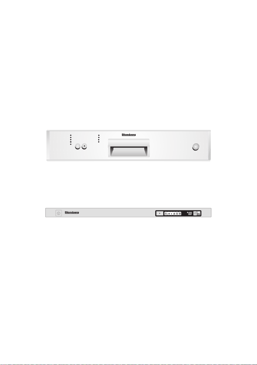
DWT 34440

Installation Manual
Dishwasher
FOR MODELS
DWT 14210 NBL00
DWT 14220 NBL00
DWT 14240 NBL00
DWT 15210 NBL00
DWT 15220 NBL00
DWT 15240 NBL00
DWT 15211 NBL00
DWT 15221 NBL00
DWT 15241 NBL00
DWT 34210 NBL00
DWT 34220 NBL00
DWT 34240 NBL00
DWT 34200 NBL00
DWT 35210 NBL00
DWT 35220 NBL00
DWT 35240 NBL00
DWT 35200 NBL00
DWT 36210 NBL00
DWT 36220 NBL00
DWT 36240 NBL00
DWT 36211 NBL00
DWT 36221 NBL00
DWT 36241 NBL00
DWT 36200 NBL00
DWT 36201 NBL00
DWT 37200 NBL00
DWT 37210 NBL00
DWT 37220 NBL00
DWT 37240 NBL00
DWT 37300 NBL00
DWT 37310 NBL00
DWT 37320 NBL00
DWT 37340 NBL00
DWT 14440 ULTRA
DWT 14410 ULTRA
DWT 14420 ULTRA
DWT 34400 ULTRA
DWT 34410 ULTRA
DWT 34420 ULTRA
DWT 34440 ULTRA
USA
Installation Manual For
Dishwasher Models
DWT 15211 NBL00
DWT 15221 NBL00
DWT 15241 NBL00
DWT 14210 NBL00
DWT 14220 NBL00
DWT 14240 NBL00
DWT 15210 NBL00
DWT 15220 NBL00
DWT 15240 NBL00
DWT 34210 NBL00
DWT 34220 NBL00
DWT 34240 NBL00
DWT 34200 NBL00
DWT 35210 NBL00
DWT 35220 NBL00
DWT 35240 NBL00
DWT 35200 NBL00
DWT 36210 NBL00
DWT 36220 NBL00
DWT 36240 NBL00
DWT 36211 NBL00
DWT 36221 NBL00
DWT 36241 NBL00
DWT 36200 NBL00
DWT 36201 NBL00
DWT 37200 NBL00
DWT 37210 NBL00
DWT 37220 NBL00
DWT 37240 NBL00
DWT 37300 NBL00
DWT 37310 NBL00
DWT 37320 NBL00
DWT 37340 NBL00
DWT 34400 ULTRA
DWT 34410 ULTRA
DWT 34420 ULTRA
DWT 34440 ULTRA
DWT 14440 ULTRA
DWT 14410 ULTRA
DWT 14420 ULTRA

Contents
1. IMPORTANT SAFETY INSTRUCTIONS 1
1.1 INSPECT THE DISHWASHER 2
1.2 HOW TO CONTACT US 2
2. TOOLS WHICH MAY BE NEEDED 3
3. MATERIALS WHICH MAY BE NEEDED 3
4. MATERIALS SUPPLIED 4
4.1 PARTS SUPPLIED 4
4.2 MANUAL BAG 4
4.3 DISHWASHER PARTS BAG 1 4
4.4 DISHWASHER PARTS BAG 2 4
4.5 PARTS ATTACHED TO THE REAR OF THE DISHWASHER 4
5. DISHWASHER SPECIFICATIONS 5
5.1 TECHNICAL FEA TURES 5
6. ENCLOSURE PREPARATION 6
6.1 ELECTRICAL PREPARATION 6
6.2 PREPARATION FOR INSTALLING MOUNTING BRACKETS 7
6.3 ADJUSTING HEIGHT 7
6.4 INSTALLING THE SIDE TRIM STRIPS 8
6.5 PREPARING THE WATER CONNECTION (A) 9
6.6 DRAIN PREPARATION 10
6.7 STEAM PROTECTION FOIL 11
7. PLACEMENT OF DISHWASHER INTO THE OPENING 12
7.1 DRAIN HOSE CONNECTION, WATER SUPPLY & ELECTRICAL CONNECTIONS 12
7.2 READJUSTING FOOT LEVELS 17
7.3 ADJUSTING THE MOV ABLE T OE KICK 17
7.4 INSTALLING THE OUTER DOOR 18
8. INSTALLER CHECKLIST 24
9. FINAL INSTRUCTIONS 24
10. SELF HELP HINTS 24
To prevent accidents, which could cause serious injury or death, as well as
machine damage read these instructions before installation and / or use.
1
USA
CAUTION
WARNING
Ý
Notice
INTRODUCTION
Please read this installation manual
and particularly the safety instructions
completely and carefully. They will save you
time and effort and help to ensure optimum
dishwasher performance.
Be sure to observe all listed warnings and
cautions. Look particularly for the icons with
exclamation marks inside. The information
icon also will provide important references.
WARNING
When installing the dishwasher, follow
basic precautions, including the
following:
The dishwasher installation must be
performed in accordance with this
installation manual. If you did not receive
an installation manual, order it by
calling 1-800-459-9848 or you may also
download it from our web site at
www.blombergappliances.com
Installation and repair should be
performed by a qualified installer.
Work by unqualified persons could be
dangerous and may void the warranty.
Do not operate the appliance if damaged,
malfunctioning, partially disassembled or
if it has missing or broken parts.
Also follow the safety instructions of the
user manual.
To reduce the risk of electric shock, fire,
or injury to persons, the installer must
ensure that the dishwasher is completely
enclosed at the time of installation.
Only connect the dishwasher to the
power supply when all installation and
plumbing work is complete.
If the dishwasher is installed in a location
that experiences freezing temperatures
(e.g. in a vacation home, cabin, etc.),
you must drain all the water from the
dishwasher’s interior. Water system
ruptures that occur as a result of freezing
are not covered by warranty.
Dishwasher must be secured to adjacent
cabinetry using the brackets provided.
Failure to do this may cause damage to
property or bodily injury.
Connect to a properly rated, protected
and sized power supply circuit to avoid
electrical overload. The dishwasher is
designed for an electrical supply of 120 V
(volts), 60 Hz (hertz), AC, connected to a
dishwasher-dedicated, properly grounded
electrical circuit with a fuse or breakers
rated for 15 amperes. Electrical supply
conductors shall be a minimum of # 14
AWG copper wire rated at 75 °C (167
°F) or higher. These requirements must
WARNING:
Indicates a potentially hazardous situation
which, if not avoided, could result in death
or serious injury.
CAUTION:
Indicates a potentially hazardous situation
which, if not avoided, may result in injury.
It may also be used to alert against unsafe
practices.
Notice:
Indicates a potentially hazardous situation
which, if not avoided, may result in damage
to the dishwasher, the table-ware, the
equipment or the environment.
1. IMPORTANT SAFETY
INSTRUCTIONS
In addition to these instructions, the
dishwasher shall be installed:
In accordance with all local codes or, in
absence of a local code,
In the United States, with the National
Electric Code,
In Canada, with the Canadian Electric
Code C22.1-latest edition/Provincial and
Municipal codes and/or local codes.
Notice :
Read these installation instructions
completely before installing and follow
them carefully. Save these installation
instructions and pass them on to any future
user.

2
USA
be met to prevent injury and machine
damage. Consult a qualified electrician if
in doubt.
Do not use any extension cord or
portable outlet device to connect the
dishwasher to a power supply.
Ensure that any plastic wrappings, bags,
small pieces etc. are disposed of safely
and kept out of the reach of children.
Danger of suffocation!
Remove the door to the washing
compartment when removing an old
dishwasher from service or discarding it.
Ensure that the appliance presents no
danger to children while being stored for
disposal.
Old appliances may contain materials
that can be recycled. Please contact
your local recycling authority about the
possibility of recycling these materials.
Notice :
The dishwasher drain hose must be
installed with a drain loop at least 28"
(710mm) off the cabinet floor; otherwise
the dishwasher may not drain properly.
This dishwasher is intended for
residential use only, and should not be
used in commercial establishments.
New installation - If the dishwasher is a
new installation, most of the work must
be done before the dishwasher is moved
into place.
Replacement - If the dishwasher is
replacing another dishwasher, check
the existing dishwasher connections for
compatibility with the new dishwasher,
and replace parts as necessary.
1.1 INSPECT THE DISHWASHER
After unpacking the dishwasher and prior
to installation, thoroughly inspect the
dishwasher for possible freight or cosmetic
damage. Report any damage immediately.
Notice :
Cosmetic defects must be reported within
10 days of installation.
Do not discard any bags or items that
come with the original package until
after the entire installation has been
completed.
1.2 HOW TO CONTACT US :
You may either call our Toll Free Number at
1-800-459-9848 or contact us via the web
site at
www.blombergappliances.com
or Contact the Blomberg Distributor for
your State or Province as listed on the
Distributor Contact List provided.vv
3
USA
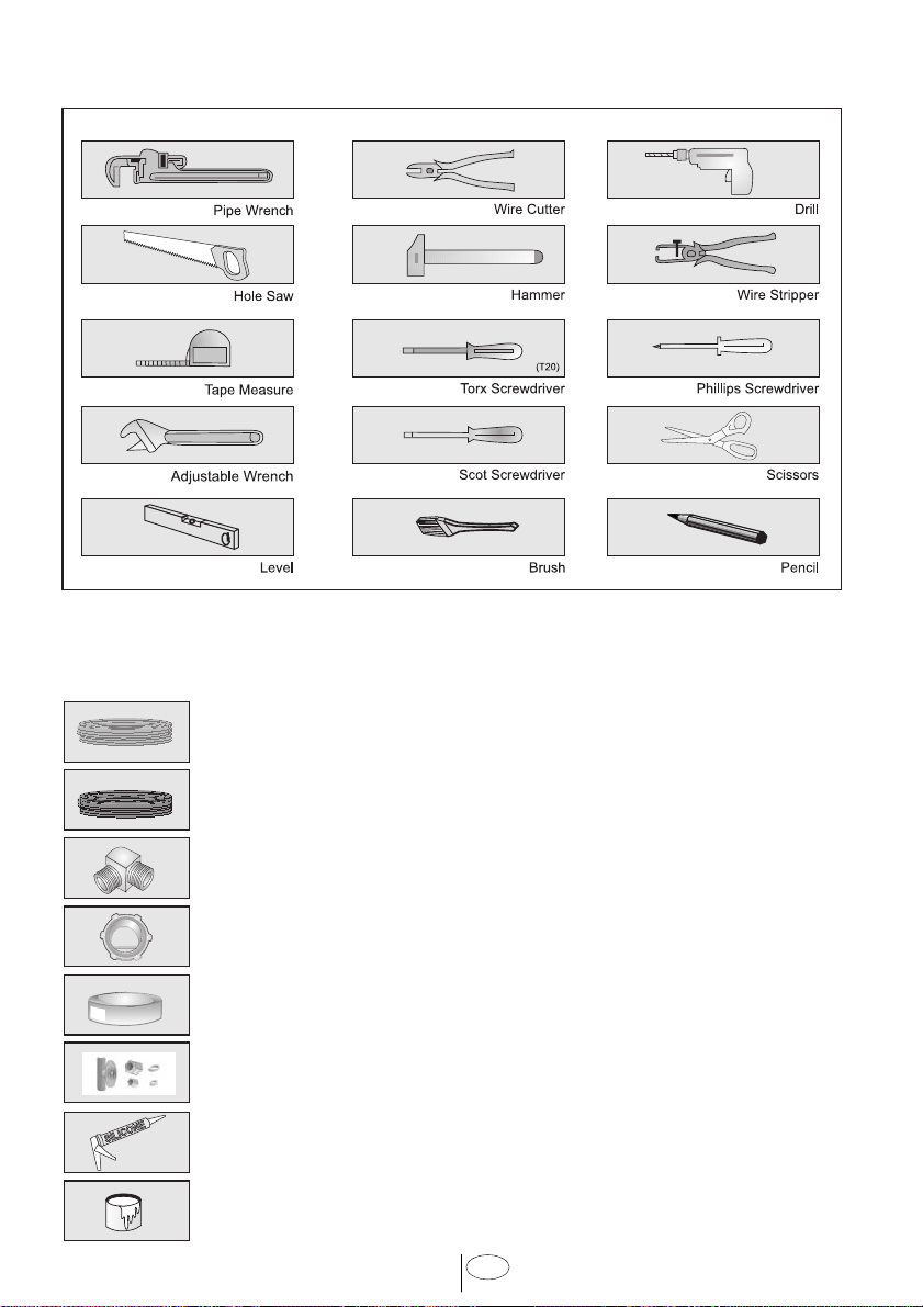
2. TOOLS WHICH MAY BE NEEDED
3. MATERIALS WHICH MAY BE NEEDED
(Additional materials may be required to comply with local codes)
Hot Water Supply Line - Minimum 3/8” O.D. copper tubing or metal braided
dishwasher supply line.
Electrical Supply Cable - Minimum #14AWG, 2 conductors, 1 ground,
insulated copper conductors.
90° elbow with 3/8” N.P.T. male threads on one leg, and sized to fit your
water supply line (copper tubing/compression fitting, or braided hose) on
the other leg.
UL listed conduit connector or strain relief.
Teflon tape or other pipe thread compound to seal plumbing connections.
Shut-off valve and fittings appropriate for hot water supply line (copper
tubing/compression fitting, or braided hose).
Silicone
Glue
4
USA
x1
x1
y.
x4
x2
x2
a.
b.
d.
e.
f.
g.
h.
c.
j.
k.
l.
m.
o.
p.
s.
v.
n.
r.
t.
x1
x1
x1
x1
x6
x1
x1
x1
x1
x3
x1
x1
x4
x4
x2
z.
x1
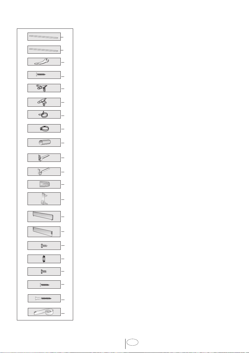
4. MATERIALS SUPPLIED
4.1 PARTS SUPPLIED
Parts for your dishwasher will come in several plastic bags.
Check your parts bags shown to make sure you have all the
parts as listed to the left.
4.2 MANUAL BAG
The dishwasher comes with a manual bag containing:
User manual,
Installation manual and
Quick reference guide.
4.3 DISHWASHER PARTS BAG 1
This dishwasher bag comes with the following parts:
a. Side Trim Strips (Left)
b. Side Trim Strips (Right)
c. Adjusting Wrench
d. Screws Ø 1/8” x 5/8” (Ø 3.5 mm x 14 mm)
e. Mounting Bracket Left
f. Mounting Bracket Right
g. Spring Clamp
h. Screw Clamp
j. Rubber Connector
k. Toe Kick Bracket - Left
l. Toe Kick Bracket - Right
m. Wire Nuts
n. Clips
o. Toe Kick (toe kick without slots)
p. Toe Kick
r. Screws Ø 1/8” x 3/8” (Ø 3.9 mm x 9 mm)
s. Plastic Caps
t. Screws Ø 3/16” x 1/4” (Ø 4mm x 6mm)
z. Steam Protection Foil
4.4 DISHWASHER PARTS BAG 2
In addition to the manual bag and the dishwasher parts bag 1
DWT 34, DWT 35, DWT 36 and DWT 37 (dishwasher models
which can accept a wooden kitchen door) also come with a
door panel installation kit which contains:
v. Screws Ø 1/8” x 5/8” (Ø 3.5mm x 14mm)
y. Screws Ø 3/16” x 13/4” (Ø 4mm x 43mm)
4.5 PARTS ATTACHED TO THE REAR OF THE
DISHWASHER
a. Side Trim Strips (Left)
b. Side Trim Strips (Right)
o. Toe Kick (toe kick without slots)
p. Toe Kick
5
USA
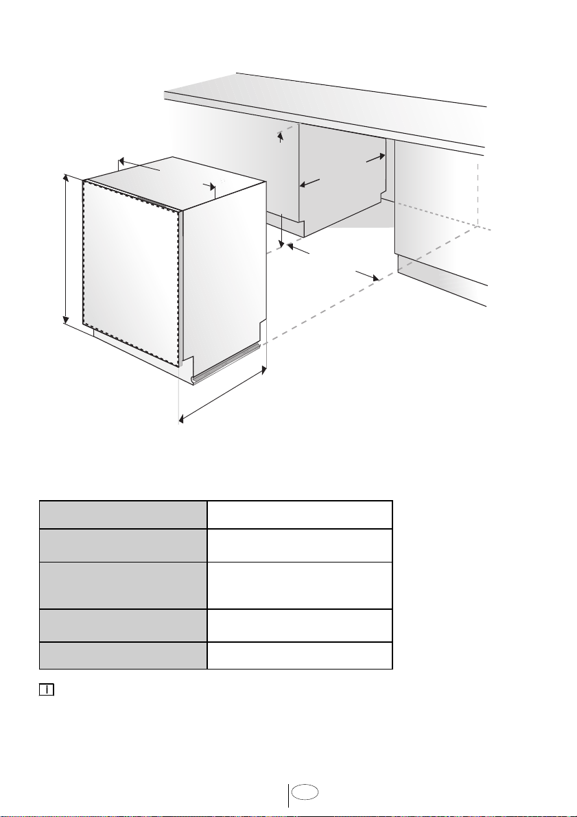
5. DISHWASHER SPECIFICATIONS
(861
mm - 911mm)
24
(610
mm
)
24
(610
mm
)
23
9
/
16
(598mm)
24 max
(610mm max)
34
- 36
1
/
4
(864mm - 920mm)
33
7
/
8
- 35
7
/
8
5.1 TECHNICAL FEATURES
Load capacity 12 place settings
Permissible water
pressure
4.35 - 145 psi (0.3 - 10 bars)
Electrical connection
120 V (volts), 12 A (amps),
60 Hz (hertz)
Total power 1200 W (watts)
Heater power 1000 W (watts)
Notice :
Because we continually strive to improve our products, we may change our specifications
and design without prior notice. This device corresponds to the following directives:
UL 749 Household Dishwasher directive.
6
USA
6. ENCLOSURE PREPARATION
Notice :
For proper dishwasher operation and appearance ensure that the enclosure has the
minimum dimensions shown in the figure above.
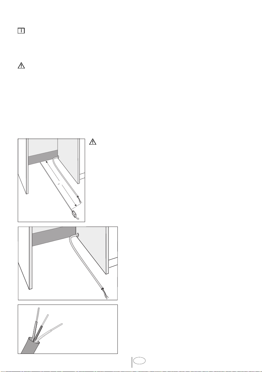
6.1 ELECTRICAL PREPARATION
WARNING
To avoid electrical shock and/or a fire hazard, make sure electrical work is properly
installed. Only qualified electricians should perform electrical work.
Before installation disconnect the power supply to the work area by unplugging the
unit, “tripping” the circuit breaker or removing the fuse.
The installer has the responsibility of ensuring that the dishwasher electrical
installation is in compliance with all national and local electrical codes and ordinances.
The dishwasher is designed for an electrical supply of 120 V, 60 Hz, AC, connected
to a dishwasher-dedicated, properly grounded electrical circuit with a fuse or breaker
rated for 15 amperes.
WARNING
Electrical supply cords must be a minimum #14AWG
copper wire.
Position the cable extending approximately 30” (760mm)
from the enclosure’s back (Figure A).
A
(
30)
B
C
Position the cable extending at the bottom
(Figure B).
Remove 2
15
/
16
” - 3
15
/
16
” (75mm-100mm) of the
cable’s outer casing, and then remove
3
/
8
” -
1
/
2
”
(9-13mm) of insulation from each wire. (Figure C)
 Loading...