

Page 1

P 4M 900-M7 S E / P4M 890-M7 TE
Setup Manual
FCC Inf or m at ion and Copyri ght
This equipment has been tested and found to comply with the limits of a Class
B digital device, pursuant to Part 15 of the FCC Rules. T hese limits are designed
to p rovid e reasonable protection against harmful interfe rence in a res idential
installation. This equipment generates, uses, and c an radiate radio frequency
energy and, if not installed and used in accordance with the instructions, may
cause harmful interference to radio communications. There is no guarantee
that interfe rence will not oc cur in a particular ins tallatio n.
The vendo r makes no repres entations o r warra nties with respec t to the
contents here and specially disclaims any implied warranties of merchantability
o r fi tness fo r a ny p u rp ose . Furthe r the ve ndo r res e rves the ri g ht to rev is e this
publication and to make c hanges to the c ontents here without obligation to
notify any party beforehand.
D uplica tion o f this publicat ion, in p art o r in wh ole, is not al lowed without first
obtaining the vendor’s approval in writing.
The content of this user’s manual is subject to be changed without notice and
we will not be respo nsible for any mistakes found in this user’s manual. All the
brand and product names are trademarks of their respec tive companies.
Page 2

Table of Contents
Chapt er 1: Introdu ct ion .............................................3
1.1 Before You Start................................................................... 3
1.2 Package Checklist................................................................3
1.3 Motherboard Features..........................................................4
1.4 Rear Panel C onnectors..........................................................5
1.5 Mo t he r bo ar d Layou t............................................................ 6
Chapt er 2: Hardware Installation..............................7
2.1 Installing Ce ntral Proce ssing Unit (CPU) ................................ 7
2.2 Fan He ade rs.........................................................................9
2.3 Installing System Memo ry.....................................................10
2.4 Con nectors and Slo ts............................................................11
Chapt er 3: Headers & Jumpers Setup .....................13
3.1 How to Setup Jum per s..........................................................13
3.2 Det ail Settin gs.....................................................................13
Chapt er 4: RAID Functions.......................................18
4.1 Operation System................................................................18
4.2 Raid Array s.........................................................................18
4.3 How RA I D Wo r k s.................................................................18
Chapt er 5: Useful Help .............................................20
5.1 Dr i ver Insta llat ion Note.......................................................20
5.2 Award BIOS Beep Code........................................................21
5.3 Extra Informati on ................................................................21
5.4 Troubleshooting...................................................................22
Chapt er 6: WarpSpeeder™ I II .................................23
6.1 Introduction ........................................................................23
6.2 System Requirement............................................................23
6.3 Installation.........................................................................24
6.4 WarpSpeede r™ III................................................................25
Appendencies: SPEC In Other Language ................30
German................................................................................................30
France..................................................................................................32
Italian..................................................................................................34
Spanish ................................................................................................36
Portuguese ...........................................................................................38
Polish...................................................................................................40
Russian ................................................................................................42
Arabic..................................................................................................44
Japanese..............................................................................................46
Page 3

CHAPTER 1: INTRODUCTION
P4M900-M7 SE/P4M890-M7 TE
1.1 B
EFORE YOU START
Tha nk you for choosing our product. Be fore you start installing the
mothe rboa rd, plea se make sure you fo llo w the instructio ns be lo w:
Prepare a dry and s table working environment with
s ufficie nt ligh ting.
Always disconnect the computer from power outlet
be fo re ope ra tion .
Befo re you take the mo the rboa rd ou t f rom a nti-s ta t ic
bag, ground yourself properly by touching any safely
grounde d appliance, or use gro unded wrist strap to
remove the static charge.
Avo id tou ch ing the compone nts o n m o the rboa rd o r the
rea r side of the board unless ne cessary. Ho ld the board
on the edge , do not try to be nd or flex the board.
Do no t lea ve an y un fas tene d small pa rts inside the
case after installation. Loose parts will cause short
circuits which ma y damage the equipment.
Keep the computer from dangerous area, such as heat
source , humid air and wate r.
1.2 PACKAGE CHECKLIST
HDD Cable X 1
I nstalla tion Guide X 1
Fully Se tup Drive r CD X 1 ( full ve rsion manual files ins ide )
Rear I/O Panel for ATX Case X 1
FDD Cable X 1 (optional)
Se ria l ATA Cab le X 1 (optiona l)
USB 2.0 Cable X1 (optional)
Se ria l ATA Po wer C able X 1 (o ptiona l)
Note: The package contents may differ by area or your motherboard version.
3
Page 4
Motherboard Manual
/
p
/
p
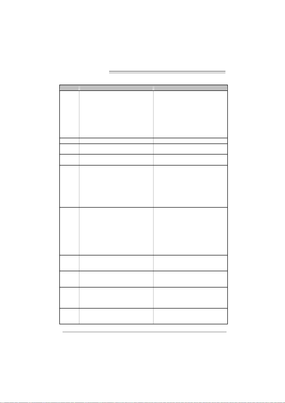
1.3 MOTHERBOARD FEATURES
P4M900-M7 SE P4M890-M7 TE
LGA 775
Intel Core2Duo/ Pentium 4 / Pentium D /
Celeron D / Celeron 4xx pr ocessor up to 3.8
GHz
CPU
FS B 533 / 800 / 106 6 MHz 533 / 800 / 106 6 MHz
Chipset
Graphic
Super I/O
Main
Memory
IDE
SATA
LAN PHY
Sound
Codec
Supports Hyper Threading
Bit / Enhanced Intel S peedStep®/ Intel
Extended Memor y 64 technology
*It is recommended to use
95W power consum pti on.
VIA P4M900
VIA VT8237A
Chr ome9 HC 3D / 2D Gr ap hic s
Max Shared Vide o Memory is 256 MB
ITE 871 2F
Provides the most commonly used legacy
Super I/O functionality.
Low Pin C ount Interf ace
Environment Control initiatives,
H/W Monitor
Fan S pee d Co ntroller
ITE' s "Smart Guardian" func tion
DIMM Slots x 2
Supports D DR2 533 / 667
Eac h DIMM supports 2 56/ 512MB/1GB/ 2GB
DDR2
Max Memory C apicity 4GB
Single Channel Mode DDR2 memory
module
Registered DIMM and ECC DIMM is not
supported
Integrated IDE Controller
Ultra DMA 33~133 Bus Master Mode
supports PIO Mo de 0~4,
Integrated Seri al ATA Controller
Data transfer rates up to 1.5 Gb/s.
SATA Version 1.0 specification compliant.
Realtek RTL 8201CL PHY/
At heros AR 8012 PHY (Optional)
10 / 100 Mb/s auto negotiation
Half / Full du plex capability
AL C662
5.1 cha nnels a udio out
High- Defi nition Au dio s upport
Execute Disable
rocessors with
LGA 775
Intel Core2Duo/ Pentium 4 / Pentium D /
Celeron D / Celeron 4xx pr ocessor up to 3.8
GHz
Supports Hyper Threading
Bit / Enhanced Intel S peedStep®/ Intel
Extended Memor y 64 technology
*It is recommended to use
95W power consum pti on.
VIA P4M890
VIA VT8237A
Unichrome Pr o IGP
Max Shared Vide o Memory is 64 MB
ITE 871 2F
Provides the most commonly used legacy
Super I/O functionality.
Low Pin C ount Interf ace
Environment Control initiatives,
H/W Monitor
Fan S pee d Co ntroller
ITE' s "Smart Guardian" func tion
DIMM Slots x 2
Suppor ts DDR2 533
Eac h DIMM supports 2 56/ 512MB/1GB/ 2GB
DDR2
Max Memory C apicity 4GB
Single Channel Mode DDR2 memory
module
Registered DIMM and ECC DIMM is not
supported
Integrated IDE Controller
Ultra DMA 33~133 Bus Master Mode
supports PIO Mo de 0~4,
Integrated Seri al ATA Controller
Data transfer rates up to 1.5 Gb/s.
SATA Version 1.0 specification compliant.
Realtek RTL 8201CL PHY/
At heros AR 8012 PHY (Optional)
10 / 100 Mb/s auto negotiation
Half / Full du plex capability
AL C662
5.1 cha nnels a udio out
High- Defi nition Au dio s upport
Execute Disable
rocessors with
4
Page 5
P4M900-M7 SE/P4M890-M7 TE
g
g
P4M900-M7 SE P4M890-M7 TE
PCI Express x 16 slot x1 PCI Express x 16 slot x1
PCI Express x 1 slot x1 PCI Express x 1 slot x1 Slots
PCI s lot x2 PCI slot x2
Floppy connector x1 Floppy connector x1
Printer Port Conn ector x1 Printer Port Connector x1
IDE C onnector x2 IDE C o nnector x2
SATA Connector x2 SATA Connector x2
Front Pa nel C o nnector x1 Front Pa nel C onnector x1
On Board
Connector
Back Panel
I/O
Board S iz e 190 mm (W) x 244 mm (L) 190 mm (W) x 244 mm (L)
Special
Feature
OS
Suppor t
Front Audi o Co nnector x1 Front A udio Connect or x1
CD-in Co nnector x1 CD-in Connect or x1
CPU Fan header x1 CPU Fan hea der x1
Syst em Fan hea der x1 Syst em Fan hea der x1
Clear CMOS header x1 Clear CMOS header x1
USB connector x2 USB connector x2
Power Connector (24pi n) x1 Power Connector (24pi n) x1
Power Connector (4pin) x1 Power Connector (4pin) x1
PS/2 Keyb oard x1
PS/2 Mo use x1
Serial Port x1
VGA Port x1
LAN port x1
USB Port x4
Audio Jack x3
RAID 0 / 1 support RAID 0 / 1 support
Windows 2000 / XP / VISTA
Biostar Reserves the ri
support for any OS with or witho ut notice.
ht t o add or r emo ve
PS/2 Keyb oard x1
PS/2 Mo use x1
Serial Port x1
VGA Port x1
LAN port x1
USB Port x4
Audio Jack x3
Windows 2000 / XP
Biostar Reserves the ri
support for any OS with or witho ut notice.
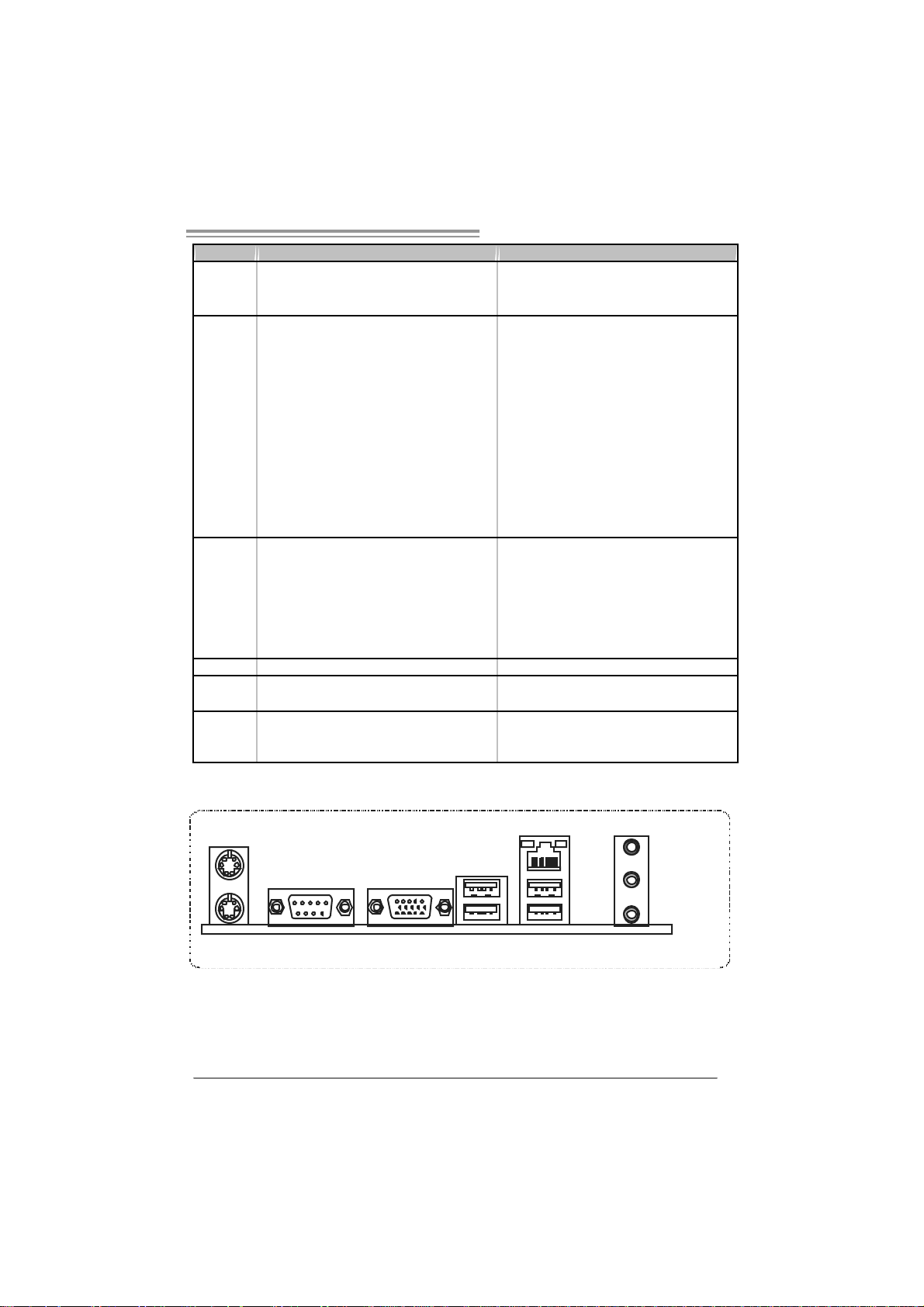
1.4 REAR PANEL CONNECTORS
PS/2
Mouse
LA N
ht t o add or r emove
Li ne I n /
Surround
Line O ut
Mic In 1/
Bass/ Center
PS/2
Keyboard
COM1 VGA
USBX2USBX2
Since t he audi o c hip s uppor ts Hig h Definiti on Audi o Speci fic ati on, the func tion of eac h audi o
jack c an be defi ne d by sof twar e. T he in put / output func tion o f eac h audi o jac k l is ted above
represents t he default s etti ng . Ho we ver , wh en c onnec ti ng e xter nal micr ophon e to t he audi o
port, pleas e us e t he Lin e In ( blu e) an d Mi c In (Pi nk) audio j ac k.
5
Page 6
Motherboard Manual
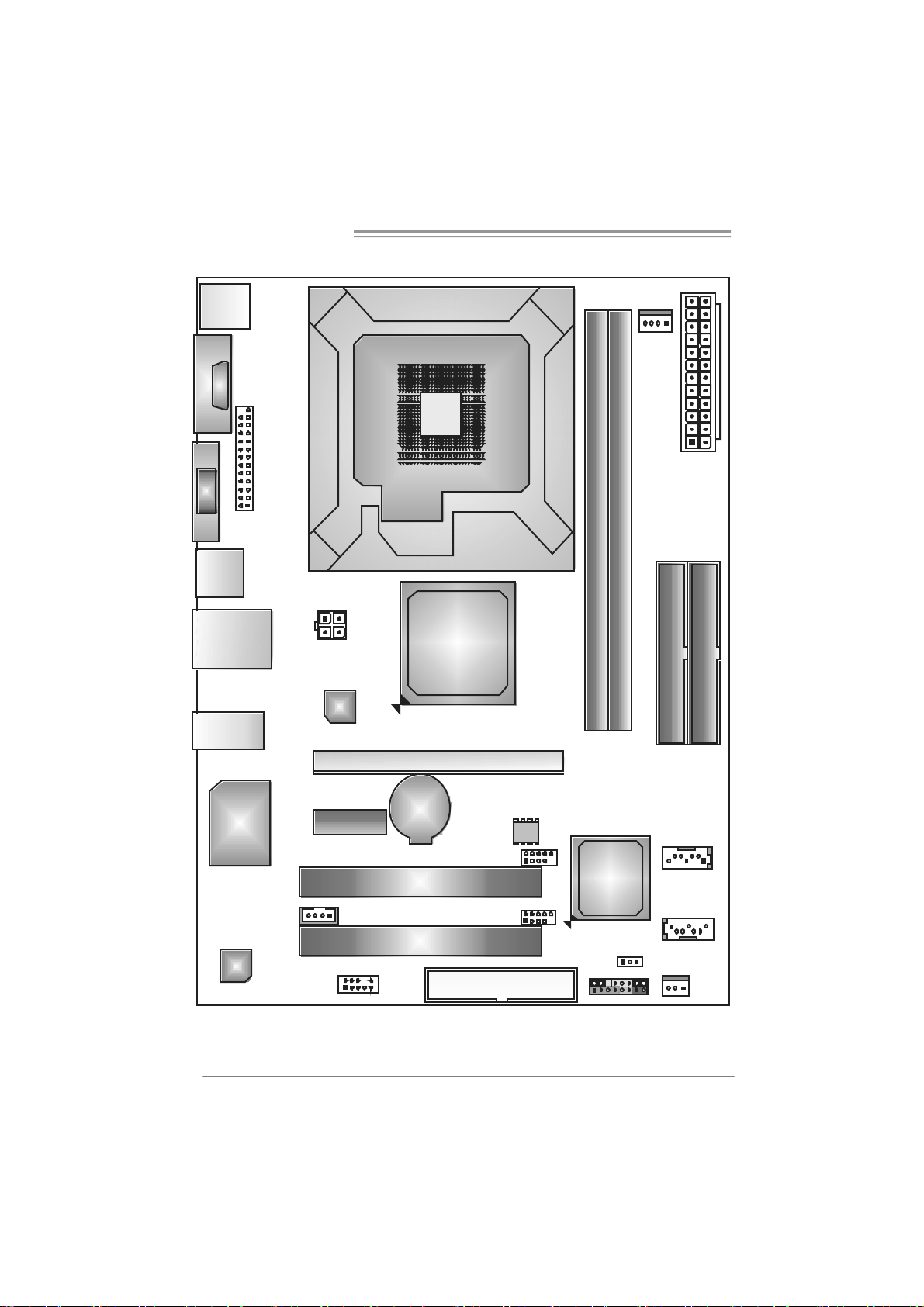
1.5 MOTHERBOARD LAYOUT
JKBMS1
C
O
J
M
C
1
O
M
1
JVGA1
JPRNT1
JU SB1
JUSBLAN1
JAUDIO1
JATXPWR2
LAN
LGA775
CPU 1
P4M900
or
P4M890
DIMM1
DIMM2
JCFAN1
JATXPWR1
IDE1
IDE2
6
Super
I/O
JCDIN1
Codec
Note: represents the 1■
JA UDIO F1
PCI -EX1 _1
PCI -E X16
BAT1
PCI1
PCI2
st
pin.
JU SB 2
JUSB3
FDD1
BI OS
VIA
VT8237A
JCMOS1
J P AN EL 1
JSATA2
JSATA1
JSFAN1
Page 7
P4M900-M7 SE/P4M890-M7 TE
CHAPTER 2: HARDW ARE INSTALLATION
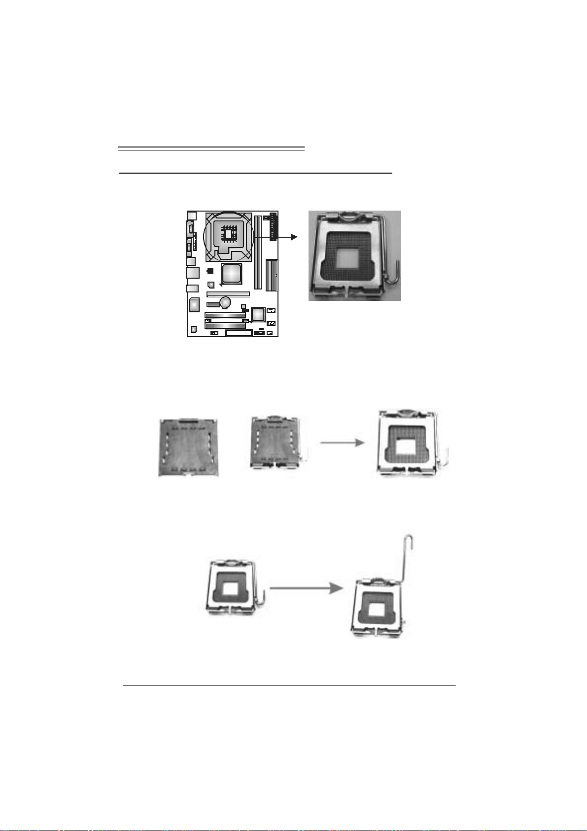
2.1 INSTALLI NG CENTRAL PROCESSI NG UNIT (CPU)
Special Notice:
Remo v e Pin Cap before installation, and ma ke goo d preservation
for future use. When the CPU is remo ved, cov er the Pin Cap on the
empty so cket to ensure pin legs won’ t be damag ed.
Pin Cap
Step 1: Pull the socket locking lever out from the socket and then raise
the lever up to a 90-degree angle.
7
Page 8
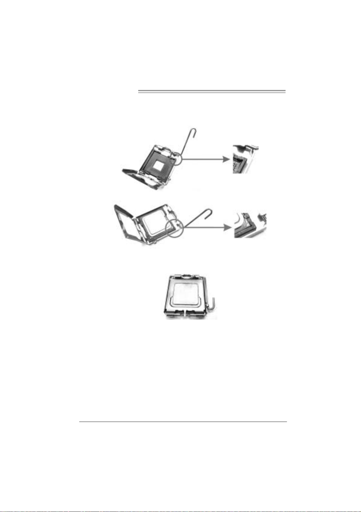
Motherboard Manual
Step 2: Look for the triangular cut edge on socket, and the golden dot on
CPU should point forwards this triangular cut edge. The CPU will
fit only in the correct orientation.
Step 2-1:
Step 2-2:
Step 3: Hold the CPU down firmly, and then lower the lever to locked
position to complete the installation.
Step 4: Put the CPU Fan and heatsink assembly on the CPU and buckle it
on the retention frame. Connect the CPU FAN power cable into
the JCFAN1. This completes the installation.
8
Page 9

P4M900-M7 SE/P4M890-M7 TE
2.2 FAN HEADERS
These fan headers support cooling-fans built in the computer. The fan
cable and connector may be different according to the fan manufacturer.
Connect the fan cable to the connector while matching the black wire to
pin#1.
JCFAN1: CPU Fa n Header
Pin
14
JSF AN1 : Sy stem F an H eader
Assignment
1 Ground
2 +12V
3 FAN RPM rate
sense
4 Smart Fan
Control
Pin
Assignment
1 Ground
2 +12V
3 FAN RPM rate
sense
13
Note:
The J SFAN1 supports 3-pin head c onnect or a nd the JCFAN1 su pports 4-pin head
conn ector . Wh en connecti ng with wires on to c onnec t ors, pl ease n ote th at t he r ed wire i s
the positi ve and s ho uld be c onnect ed to pi n#2, an d th e blac k wire i s Groun d and s ho uld
be c onnect ed t o GND .
9
Page 10

Motherboard Manual
2.3 INSTALLING SYSTEM MEMORY
A. Me mo ry Modu le s
DIM M1
DIM M2
1. Unlock a DIMM slot by pressing the retaining clips outward. Align a
DIMM on the slot such that the notch on the DIMM matches the
break on the Slot.
2. Insert the DIMM vertically and firmly into the slot until the retaining
chip snap back in place and the DIMM is properly seated.
B. Memory Capacity
10
DI MM Socket
Location
DIMM1 256MB/512MB/ 1GB/2GB
DIMM2 256MB/512MB/ 1GB/2GB
DDR Module
To tal M e m o r y
Size
Max is 4GB.
Page 11
P4M900-M7 SE/P4M890-M7 TE
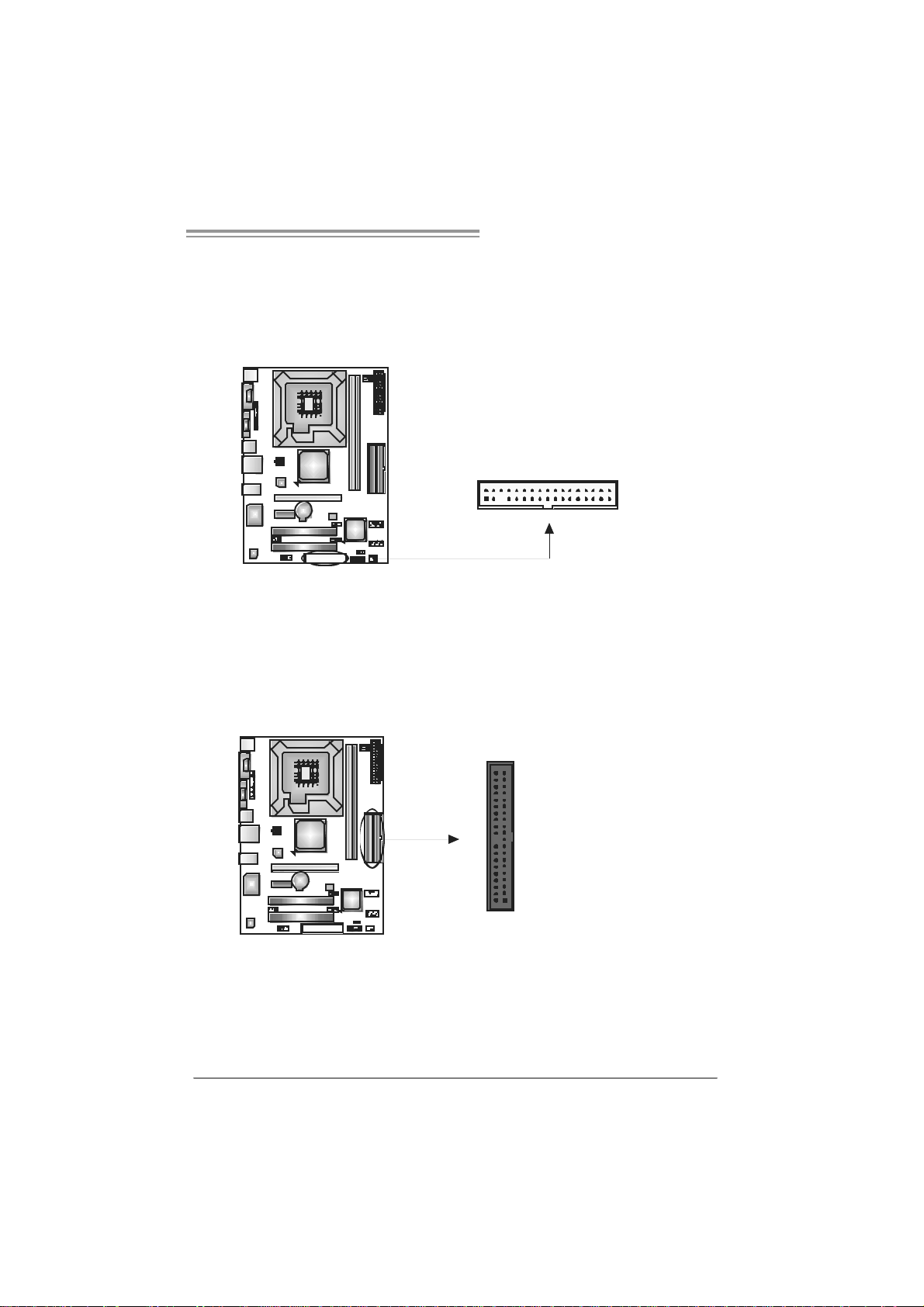
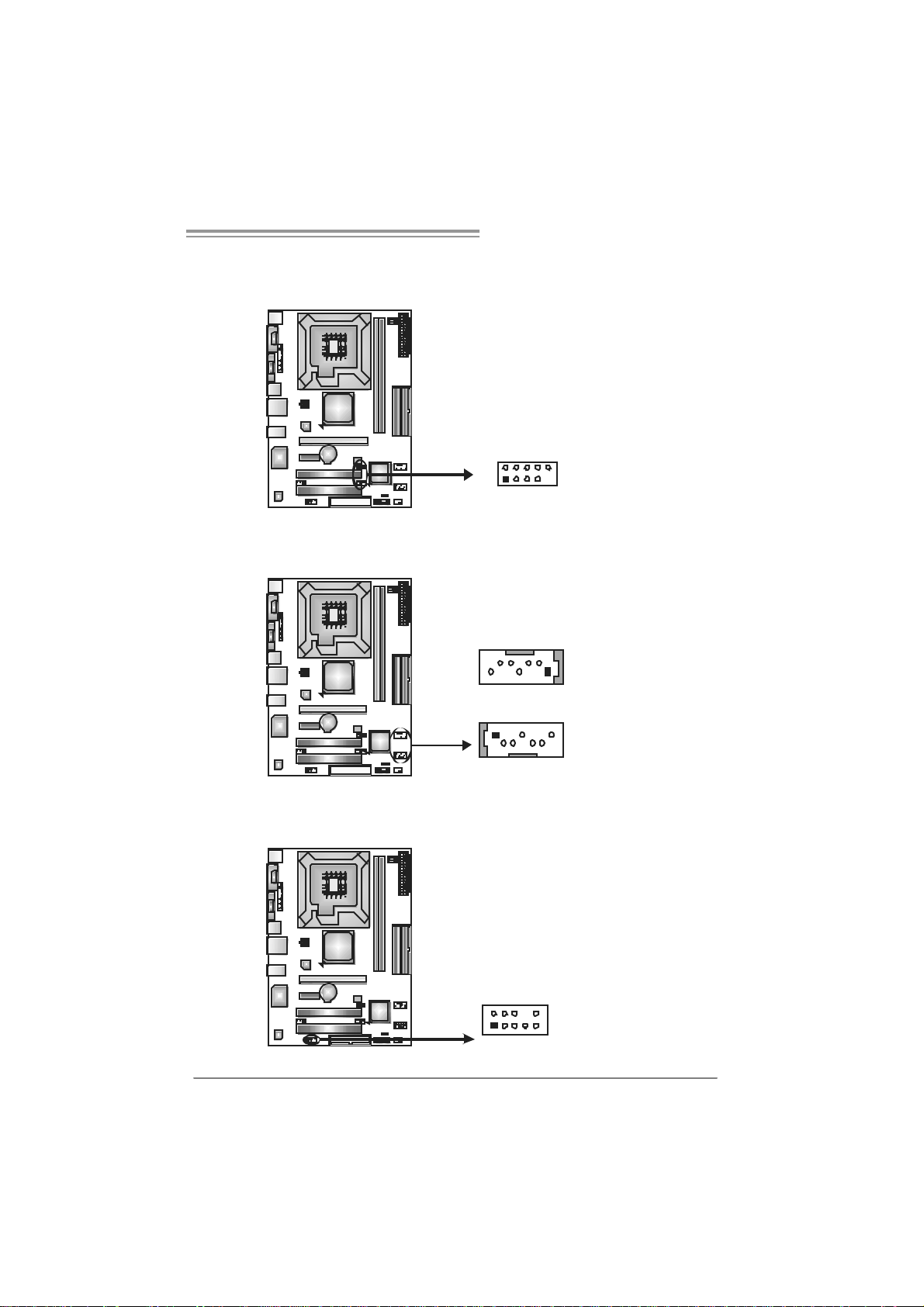
2.4 CONNECTORS AND SLOTS
FDD1: Floppy Disk Conne c tor
The motherboard prov ides a standard floppy disk connector that supports 360K,
720K, 1.2M, 1.44M and 2.88M floppy disk ty pes. This connector s upports t he
prov ided f loppy driv e ribbon cable.
IDE1/IDE2 : Hard Disk Connec tors
The motherboard has a 32-bit Enhanced PCI ID E Controller that prov ides PIO
Mode 0~4, Bus Master, and Ultra DMA 33/66/100/133 f unc tionality. It has two
HDD connectors: IDE1 (primary ) and ID E2 (secondary).
The IDE connectors can connect a master and a slav e driv e, so you can
connect up to four hard disk drives. The f irs t hard drive should always be
connected to IDE1.
2
1
3940
21
34
33
IDE2IDE1
11
Page 12
Motherboard Manual
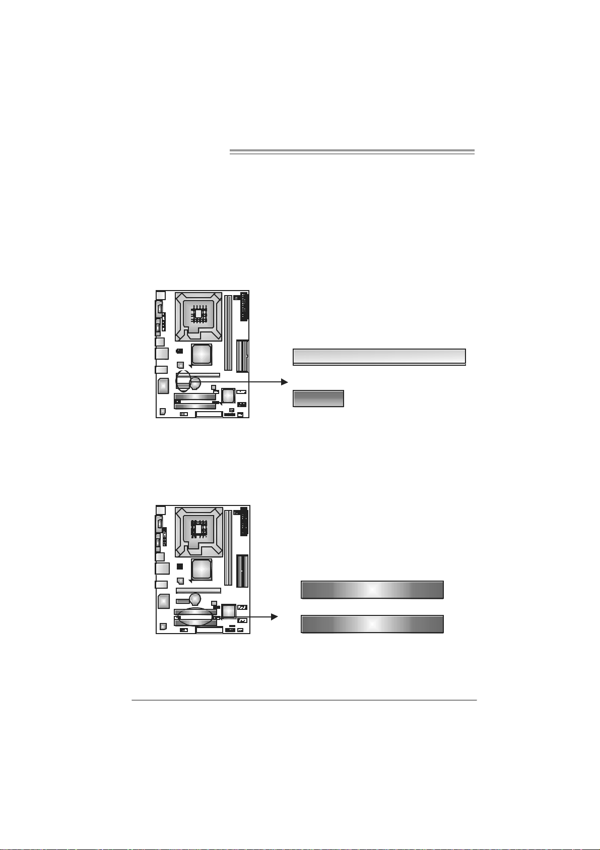
PCI-EX16: PCI-Expr es s x1 6 S lot
- PCI-Express 1.0a compliant.
- Maximum theoret ical realized bandwidth of 4GB/s sim ultaneously per
direction, f or an aggregate of 8GB/ s totally.
PCI-EX1_1: PCI-Express x1 Sl ot
- PCI-Express 1.0a compliant.
- Data transf er bandwidth up t o 250MB/s per direction; 500MB/s in total.
- PCI-Express supports a raw bit-rat e of 2.5Gb/s on the data pins.
- 2X bandwidth ov er the traditional PCI archit ecture.
PCI-EX16
PCI-EX1_1
PCI1/PC I2: Peri phe ral Compo nent Interconnect Slots
This motherboard is equipped with 2 standard PCI slots. PCI stands f or
Peripheral Component Interconnect, and it is a bus standard for expansion
cards. This PCI slot is designated as 32 bits.
12
PCI1
PCI2
Page 13

P4M900-M7 SE/P4M890-M7 TE
CHAPTER 3: HEADERS & JUMPERS SETUP
3.1 HOW TO SET UP JUMPERS
The illustration shows how to set up jumpers. When the jumper cap is
placed on pins, the jumper is “close”, if not, that means the jumper is
“open”.
Pin opened Pin closed Pin1-2 closed
3.2 DETAIL SETT INGS
JPANEL1: Front Panel Header
This 16-pin connector includes Power-on, Reset, HDD LED, Power LED, Sleep
button and speaker connection. It allows user to c onnect the PC cas e’s f ront
panel switch functions.
PWR_LED
SLP
9
18
SPK
++
+
On /O ff
-
-
RS T
16
HL E D
Pin Assignment Function Pin Assignment Function
1 +5V 9 Sleep control
2 N/A 10 Ground
3 N/A 11 N/A N/A
4 Speaker
5 HDD LED (+) 13 P ower LED (+)
6 HDD LED (-)
7 Ground 15 Power button
8 Reset control
Speaker
Connector
Hard drive
LED
Reset button
12 P owe r LED (+)
14 P owe r LED (-)
16 Ground
Sleep button
Power LED
Power-on button
13
Page 14
Motherboard Manual
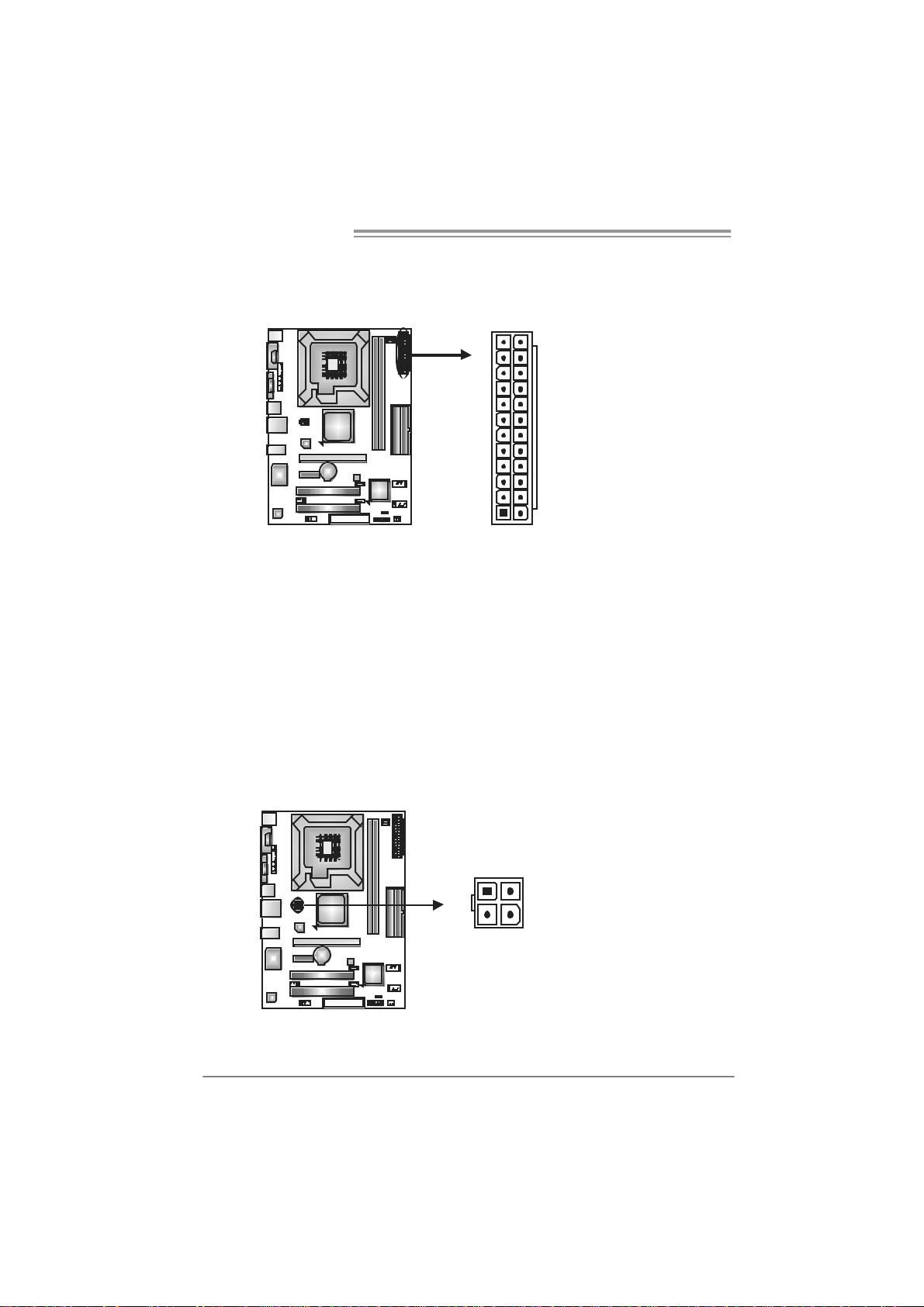
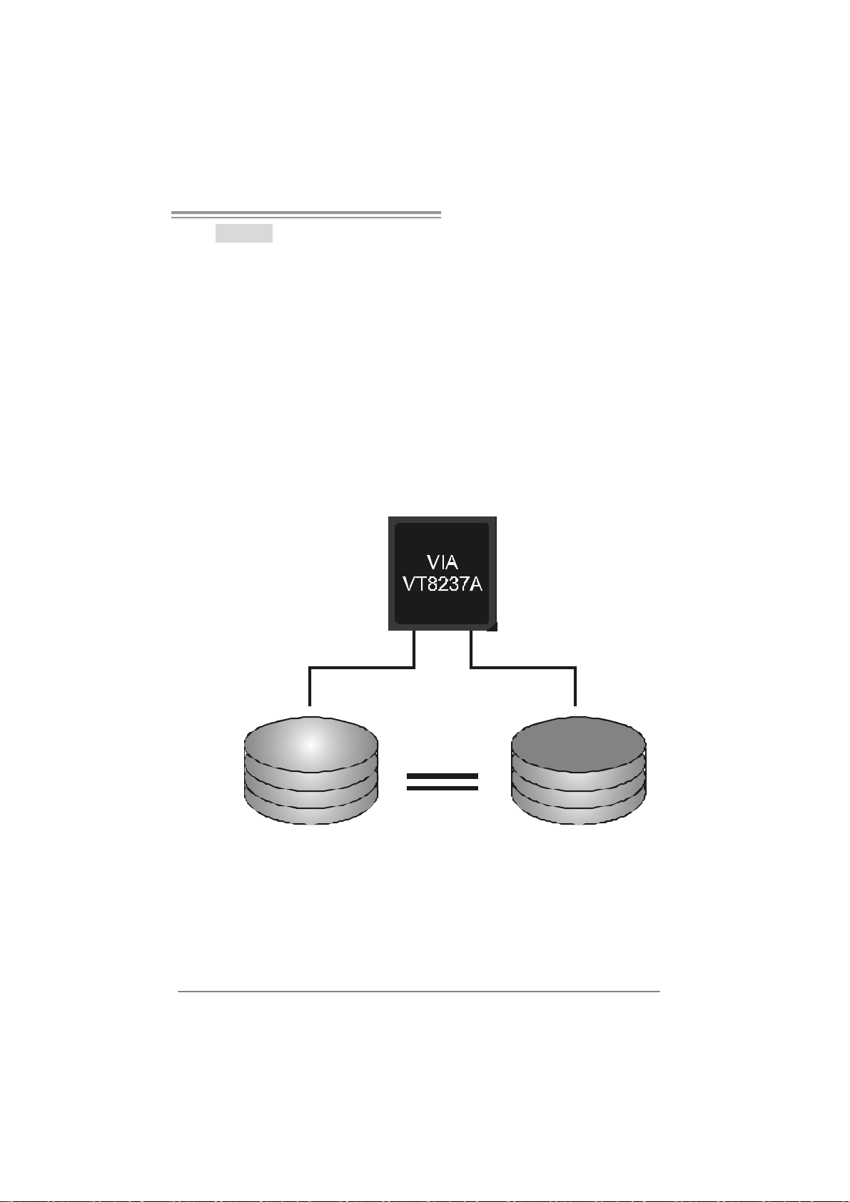
ATX Power So urce Connect or: JATXPWR1
JATXPWR1 allows user to connect 24-pin power connector on the ATX power
supply.
12
1
Pin Assignment Pin Assignment
24
13
13 +3.3V 1 + 3.3V
14 -12V 2 + 3.3V
15 Gr ound 3 Gr oun d
16 PS_ON 4 + 5V
17 Gr ound 5 Gr oun d
18 Gr ound 6 + 5V
19 Gr ound 7 Gr oun d
20 NC 8 PW_ OK
21 +5V 9 Standb y Vol t age+5V
22 +5V 10 +12V
23 +5V 11 +12V
24 Gr ound 12 +3.3V
JATXPWR 2: AT X Powe r Source Conne ctor
By connecting this connector, it will provide +12V to CPU power circuit.
Pin
1
23
4
Assignment
1 +12V
2 +12V
3 Ground
4 Ground
14
Page 15
P4M900-M7 SE/P4M890-M7 TE
JUSB2/JUSB3: Headers for USB 2.0 Ports at Fron t Panel
This header allows user to connect additional USB cable on the PC f ront panel,
and also can be connected with internal USB devices, like USB card reader.
Assignment
Pin
1 +5V (fused)
2 +5V (fused)
3 USB4 USB5 USB+
6 USB+
7 Ground
210
19
JUSB2
JUSB3
8 Ground
9 Key
10 NC
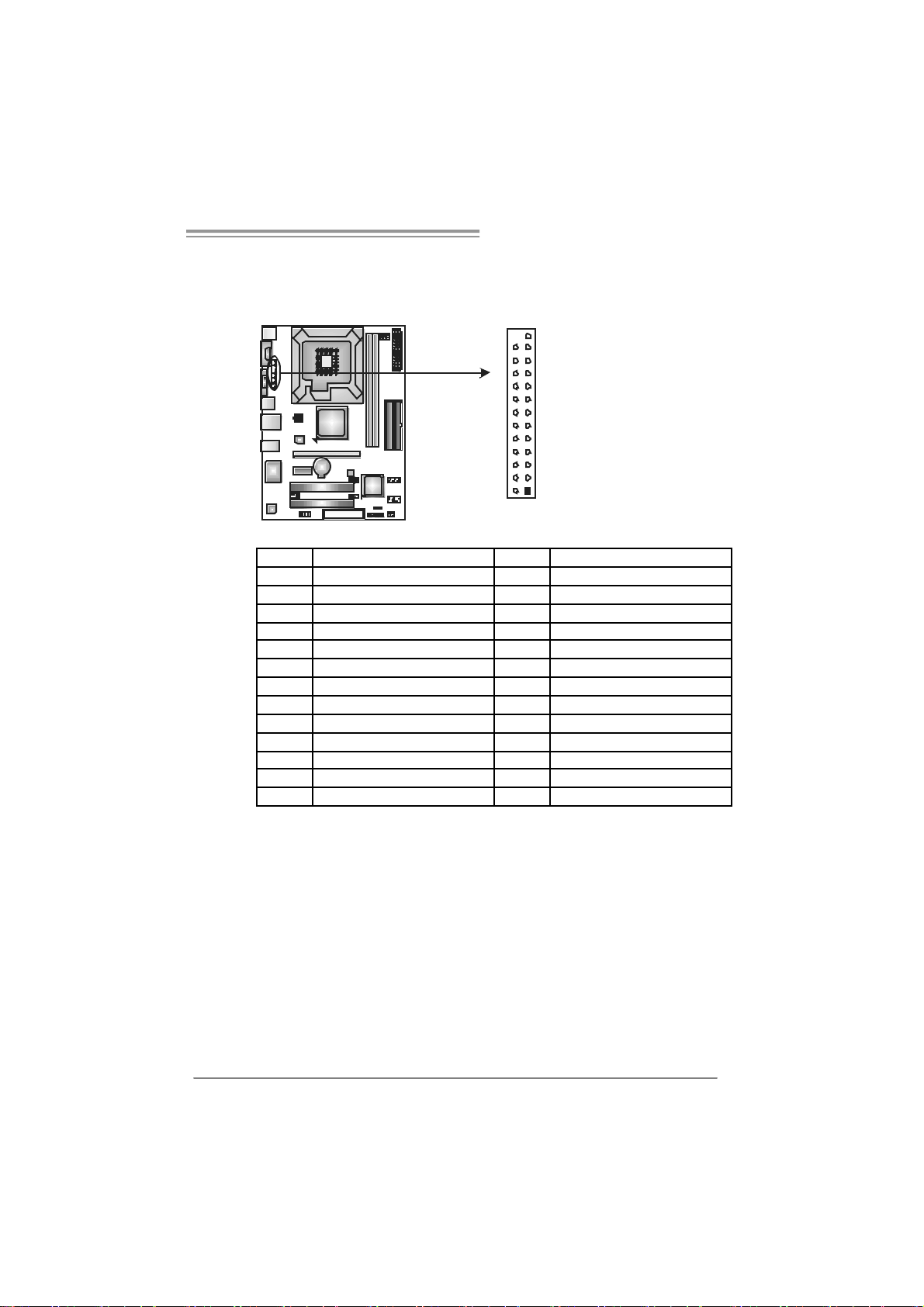
JSATA1/JS ATA2: Serial ATA Connectors
The motherboard has a PCI to SATA Controller with 2 channels SATA interf ace,
it satisfies the SATA 1.0 spec and with transfer rate of 1.5Gb/s.
Pin
JSATA2
147
14 7
Assignment
1 Ground
2 TX +
3 TX 4 Ground
5 RX6 RX+
7 Ground
J SATA 1
JAUDIOF1 : Fron t Panel Au dio Header
This header allows user to connect the front audio output cable with the PC front
panel. It will disable the output on back panel audio connectors.
Pin Assignment
1 Mic Left in
2 Ground
3 Mic Right i n
4 GPIO
5 Right line i n
6 Jack Sense
7 Front Sens e
210
19
8 Key
9 Left l ine in
10 Jack Sense
15
Page 16

Motherboard Manual
JCDIN1: CD-R OM A ud io-in Con nector
This connector allows user to connect the audio source f rom t he v ariaty dev ices,
like CD-ROM, DVD-ROM, PCI sound c ard, PCI TV turner card etc.
JCMOS 1 : C l ea r CMOS Hea der
By placing the jumper on pin2-3, it allows user to restore the BIOS saf e set ting
and the CMOS data, please carefully f ollow the procedures to avoid damaging
the motherboard.
Assignment
Pin
1 Left Channel Input
2 Ground
3 Ground
4 Right Channel Input
14
13
Pin 1-2 Close:
Normal Operation (default).
16
1
13
Pin 2-3 Close:
Clear CMOS data.
※ Clear CMOS Procedures:
1. Remov e AC power line.
2. Set the jumper to “Pin 2-3 close”.
3. Wait for f ive seconds.
4. Set the jumper to “Pin 1-2 close”.
5. Power on the AC.
6. Reset y our desired password or clear the CMOS data.
3
Page 17
JPRNT1: Printer Port Connector
This header allows you to connector printer on the PC.
Pin Assignment Pin Assignment
1 -Strobe 14 Ground
2 -ALF 15 Data 6
3 Data 0 16 Ground
4 -Error 17 Data 7
5 Data 1 18 Ground
6 -Init 19 -ACK
7 Data 2 20 Ground
8 -Scltin 21 Busy
9 Data 3 22 Ground
10 Ground 23 PE
11 Data 4 24 Ground
12 Ground 25 SC LT
13 Data 5 26 Key
P4M900-M7 SE/P4M890-M7 TE
25
1
2
17
Page 18

Motherboard Manual
CHAPTER 4: RAID FUNCTIONS
4.1 OPERA TIO N SYSTEM
z Supports Windows XP Home/Prof es sional Edition, and Windows 2000 Prof essional.
4.2 RAID ARRAYS
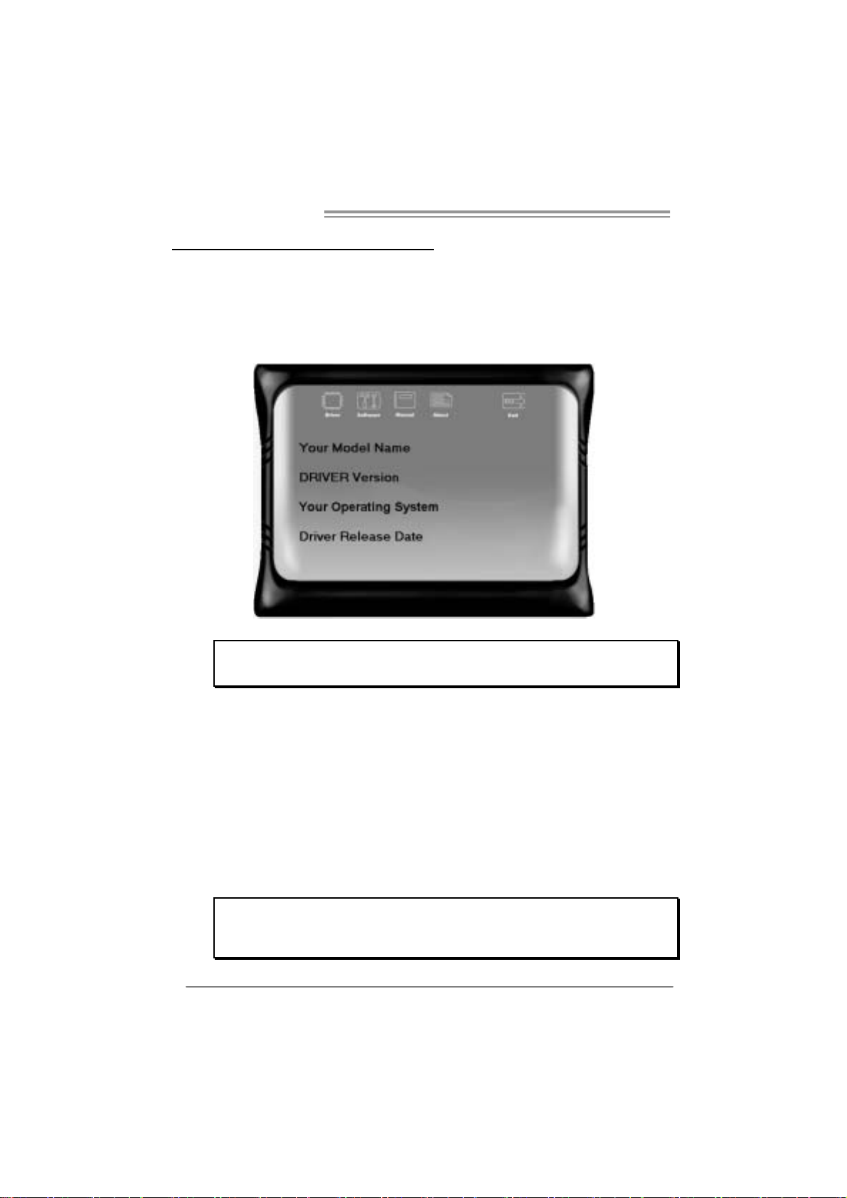
RAID supports the following ty pes of RAID arrays:
RAID 0: RAID 0 defines a disk striping scheme that improves disk read and write times for
RAID 1: RAID 1 defines t echni ques for mirrori ng data.
many applications.
4.3 HOW RAID WORKS
RAID 0:
The controller “ stripes ” data across multipl e drives in a RAID 0 array sy stem. It breaks
up a large file into smaller blocks and performs disk reads and writes across multiple
drives in parall el. The size of each blo ck is determined by the stripe size parameter,
which you set during the creation of the RAID set based on the system environment. This
technique redu ces overall disk access time and offers high b andwidth.
Fea tures and Be nefits
Drives: Minimum 1, and maximum is up to 6 or 8. Depending on the
platform.
Uses: Intended for non-critical data requiring high dat a throughput, or any
env ironment that does not require f ault tolerance.
Benefits: prov ides inc reased data throughput, especially f or large files. No
capacity loss penalty f or parity.
Drawbacks: Does not deliver any f ault tolerance. If any drive in t he array
f ails, all data is lost.
Fault Tolerance: No.
18
Block 1
Block 3
Block 5
Block 2
Block 4
Block 6
Page 19
P4M900-M7 SE/P4M890-M7 TE
RAID 1:
Every read and w rite is actually carried out in parallel across 2 disk driv es in a RAID 1
array system. The mirrored (backup) copy of th e data can reside on the same disk or on a
second redundant drive in the array. RAID 1 provides a hot-standby copy of data if the
active volume or d rive is corrup ted or becomes un availabl e because of a hardware failure.
RAID techniques can be applied for high-availability solutions, or as a form of automatic
backup that eliminates tedious manual backups to more expensive and less reliable
me d i a .
Fea tures and Be nefits
Drives: Minimum 2, and maximum is 2.
Uses: RAID 1 is ideal for small dat abases or any other applicat ion that
requires f ault tolerance and minimal c apacity.
Benefits: Prov ides 100% data redundancy. Should one drive f ail, the
controller switches to the other drive.
Drawbacks: Requires 2 drives for t he storage space of one drive.
Perf ormance is impaired during driv e rebuilds.
Fault Tolerance: Yes.
Block 1
Block 2
Block 3
Block 1
Block 2
Block 3
19
Page 20
Motherboard Manual
CHAPTER 5: USEFUL HE LP
5.1 DRIVER INSTALLATION NOTE
After you installed your operating system, please insert the Fully Setup
Driver CD into your optical drive and install the driver for better system
performance.
You will see the following window after you insert the CD
The setup guid e will auto dete ct your motherboa rd and operating system.
Note:
If this windo w didn’ t show up af t er you ins ert th e Driv er CD, ple ase use fi le bro ws er to
locate an d e xecu te th e fi le SETUP.E XE under yo ur optical dri ve.
A. Driver Insta ll ation
To install the driver, please click on the Driver icon. The setup guide will
list the compatible driver for your motherboard and operating system.
Click on each device driver to launch the installation program.
B. Software Installation
To install the software, please click on the Software icon. The setup guide
will list the software available for your system, click on each software title
to launch the installation program.
C. Manual
Aside from the paperback manual, we also provide manual in the Driver
CD. Click on the Manual icon to browse for available manual.
Note:
You will need Acrobat Reader to open the manual file. Pleas e download the latest version
of Acrobat Reader soft ware fro m
http://www.adobe.com/products/acrobat /readstep2.html
20
Page 21
P4M900-M7 SE/P4M890-M7 TE
5.2 AWARD BIOS BEEP CODE
Beep Sound Meanin g
One long beep followed by two short
beeps
High-low siren sound CPU overheated
One Short beep when system boot-up No error found during POST
Long beeps every other second No DRAM detected or ins tall
Video card not found or v ideo card
memory bad
System will shut down automatically
5.3 EXT RA INFORMATION
CPU Overheated
If the system shutdown automatically after power on system for
seconds, that means the CPU protection function has been activated.
When the CPU is over heated, the motherboard will shutdown
automatically to avoid a damage of the CPU, and the system may not
power on again.
In this case, please double check:
1. The CPU cooler surface is placed evenly with the CPU surface.
2. CPU fan is rotated normally.
3. CPU fan speed is fulfilling with the CPU speed.
After confirmed, please follow steps below to relief the CPU protection
function.
1. Remove the power cord from power supply for seconds.
2 . Wa i t fo r se c o nds.
3. Plug in the power cord and boot up the system.
Or you can:
1. Clear the CMOS data.
(See “Close CMOS Header: JCMOS1” section)
2 . Wa i t fo r se c o nds.
3. Po we r on the syste m again.
21
Page 22

Motherboard Manual
e
5.4 TROUBLESHOOTING
Probable Solution
1. No power to the system at all
Power light don’t illuminate, f an
inside power supply does not turn
on.
2. Indicator light on key board does
not turn on.
System inoperativ e. Key board lights
are on, power indicator lights are lit,
and hard driv e is spinning.
System does not boot from hard disk
driv e, can be booted f rom optical driv e.
System only boots f rom optical driv e.
Hard disk can be read and applications
can be used but booting from hard disk
is impossible.
Screen message says “Invalid
Configuration” or “CMOS F ailure.”
Cannot boot system after inst alling
second hard driv e.
1. Make sure power cable is
securely plugged in.
2. Replace cable.
3. Cont act technical s upport.
Using even pressure on bot h ends of
the DIMM, press down firmly until the
module snaps into place.
1. Check cable running from disk to
disk controller board. Make sure
both ends are securely plugged
in; c hec k t h e d r iv e ty p e in t he
standard CMOS setup.
2. Backing up the hard driv e is
extremely important. All hard
disks are capable of breaking
down at any time.
1. Back up data and applic ations
files.
2. Ref ormat the hard drive.
Re-install applications and data
using backup disks.
Review system ’s equipment. Make sur
correct inf ormation is in setup.
1. Set master/slave jumpers
correctly.
2. Run SETUP program and select
correct driv e ty pes. Call the drive
manufacturers f or com patibility
with other drives.
22
Page 23

P4M900-M7 SE/P4M890-M7 TE
CHAPTER 6: WARPSPEEDE R™ III
6.1 INTRODUCTION
[WarpSpeeder™ III], a new powerful control utility, features three
user-friendly functions including Overclock Manager, Overvoltage
Manager, and Hardware Monitor.
With the Overclock Manager, users can easily adjust the frequency they
prefer or they can get the best CPU performance with just one click. The
Overvoltage Manager, on the other hand, helps to power up CPU core
voltage and Memory voltage. The cool Hardware Monitor smartly indicates
the temperatures, voltage and CPU fan speed as well as the chipset
information. Also, in the About panel, you can get detail descriptions about
BIOS model and chipsets. In addition, the frequency status of CPU,
memory, VGA and PCI along with the CPU speed are synchronically
shown on our main panel.
Moreover, to protect users' computer systems if the setting is not
appropriate when testing and results in system fail or hang,
[WarpSpeeder™ III] technology assures the system stability by
automatically rebooting the computer and then restart to a speed that is
either the original system speed or a suitable one.
6.2 S
YSTEM REQUI REMENT
OS Support: Windows 98 SE, Windows Me, Windows 2000, Windows XP
DirectX: DirectX 8.1 or above. (The Windows XP operating system
includes DirectX 8.1. If you use Windows XP, you do not need to install
DirectX 8.1.)
23
Page 24
Motherboard Manual
6.3 INSTALLATION
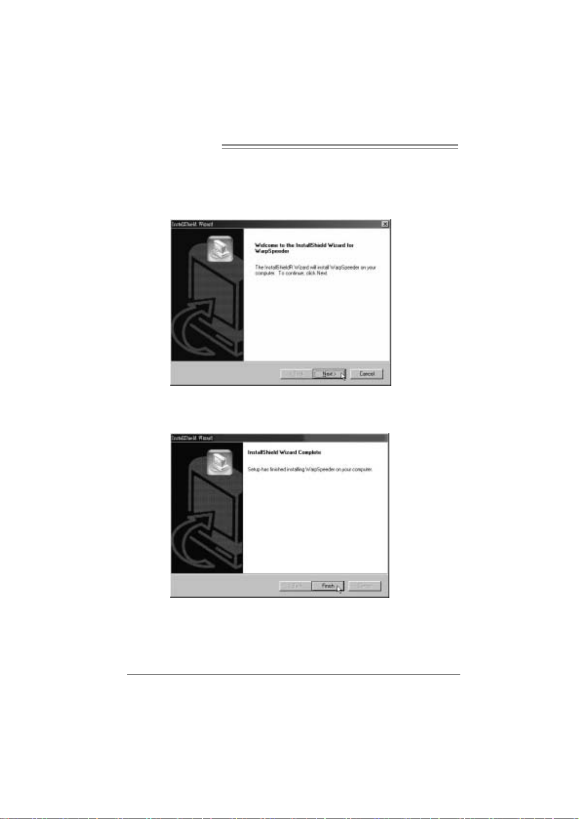
1. Execute the setup execution file, and then the following dialog will pop
up. Please click “Next” button and follow the default procedure to
install.
2. When you see the following dialog in setup procedure, it means setup
is completed. Click “Finish” button.
24
Usage :
The following figures are only for reference, the screen printed in this
user manual will change according to your motherboard on hand.
Page 25
P4M900-M7 SE/P4M890-M7 TE
6.4 WARPSPEEDER™ III
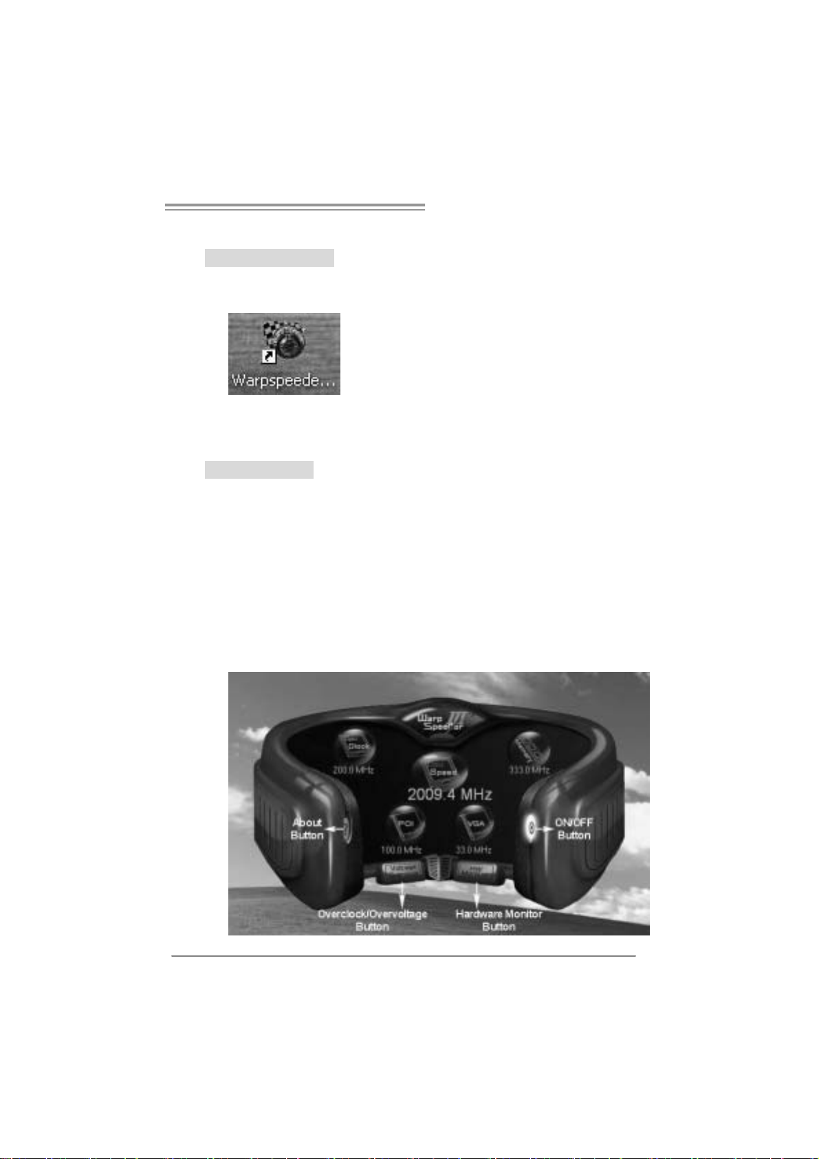
1. Desktop Icon:
After the [WarpSpeeder™ III] has been installed, a [WarpSpeeder™ III]
icon will appear on the desktop, just like the icon shown below.
Now you can launch the [WarpSpeeder™ III] utility simply by
double-clicking the desktop icon.
2. Main Panel
If you double-click the desktop icon, [WarpSpeeder™ III] will be
launched. Please refer to the following figure; the utility’s first window
yo u will see i s Ma in Panel.
Main Pane l contains features as foll ows:
a. Display the CPU Speed, CPU external clock, Memory clock, VGA
clock, and PCI clock information.
b. Contains About, Voltage/Overclock, and Hardware Monitor
Buttons for invoking respective panels. The On/Off button is for
closing the program.
25
Page 26

Motherboard Manual
3. Over clock/Over voltage Panel
Click the Overclock/Overvoltage button in the Main Panel, the button
will be highlighted and the Overclock/Overvoltage Panel will show
up as the following figure. As you can see, the Overclock Panel is
on the right side, and the Overvoltage Panel is on the left side.
26
Page 27

P4M900-M7 SE/P4M890-M7 TE
Overclock Panel cont ains these features :
a. “Auto-Overclock”:
User can click thi s button and [Wa rpSpee der™ III] will set the be st
and stable performance and frequency automatically. A warning
dialog as below will show up to notify you that the system may
become unstable, click on “OK” to proceed.
Then [WarpS peede r™ III] uti lity will exe cute a series of testi ng
un til system fail . T hen system will do fail-sa fe reboot by using
Watchdog function. After reboot, launch the [WarpSpeeder™ III]
utility again and the utility will load the previously verified best and
stable frequency.
b. “Verify”:
If you use the “Manual Adjust” bar to adjust the CPU frequency,
then you can click this button and [WarpSpeeder™ III] will proceed
a testing for current frequency. If the testing is ok, then the current
frequency will be saved into system registry. If the testing fails,
system will do a fail-safe re bootin g. After reboot, the
[WarpSpeeder™ III] utility will restore to the hardware default
setting.
Warning:
Manually overclock is potentially dangerous, especially when the
ov erclocking percentage is over 110 %. W e strongly recommend you
v erify ev ery speed you overcloc k by click the Verify button. Or, you can
just click Auto ov erc lock button and let [WarpSpeeder™ III]
automatically gets t he best result f or y ou.
c. “V3 Engine”/“V6 Engine”/“V9 Engine”:
Provide user the ability to do real-time overclock adjustment.
d. “Recovery”:
Click this button and the [WarpSpeeder™ III] utility will restore all
values to the hardware default setting.
27
Page 28

Motherboard Manual
Overvolta ge Pa n el contains th ese fe atures:
a. “CPU Voltage”:
This function allows user to adjust CPU voltage. Click on “+” to
increase or “-“ to decrease the CPU voltage.
b. “Memory Voltage”:
This function allows user to adjust Memory voltage. Click on “+”
to i ncrease or “-“ to decrease the Memory vo ltage.
4. Hardware Monitor Panel
Click the Ha rdware Monitor button i n Main Panel, th e bu tton will be
highlighted and the Hardware Monitor panel will show up as the
following figure.
In this panel, you can get the real-time status information of your
system . The informati on will be refreshed every 1 second.
28
Page 29

P4M900-M7 SE/P4M890-M7 TE
5. About Panel
Click the “about” button in Main Panel, the button will be highlighted
and the About Panel will show up as the following figure.
In this panel, you can get model name and detail information in hints
of all the chipset that are related to overclocking. You can also get
the the version number of [WarpSpeeder™ III] utility.
Note :
Because the overclock, overvoltage, and hardware monitor features
are controlled by several separate chipset, [WarpSpeeder™ III]
divide these features to separate panels. If one chipset is not on
board, the correlative button in Main panel will be disabled, but will
not interfere other panels’ functions. This property can make
[WarpSpeeder™ III] utility more robust.
29
Page 30

Motherboard Manual
/
/
p
/
/
p
APPENDENCI ES: SPEC IN OTHER LANGUAGE
GERMAN
P4M900-M7 SE P4M890-M7 TE
LGA 775
Intel Core2Duo/ Pentium 4 / Pentium D /
Celeron D / Celeron 4xx Prozessoren mit
bis zu 3,8 GHz
CPU
FS B 533 / 80 0 / 106 6 MHz 533 / 80 0 / 1066 M Hz
Chipsatz
Grafi k
Super E/A
Arbeitsspeic
her
IDE
SATA
Unterstützt Hyper-Threading / Execute
Dis able Bit
Intel Architecture-64 / Extended Memory
64 Tech nology
*It is recommended to use
95W power consum pti on.
VIA P4M900
VIA VT8237A
Chr ome9 HC 3D / 2D Gr ap hic s
Max. 256M B gemei nsam be nutz ter
Vi deospeicher
ITE 871 2F
Biet et die h äufi g verwe ndete n alte n Super
E/A-Funkt io nen.
Low Pin C ount-Sc hnit ts telle
Umgebungs kontroll e,
Hardware-Überwachun g
Lüfterdrehzahl-Controller
"Smart Guar dian"-Funktion von ITE
DDR2 DIMM-St eckplät ze x 2
Unterstützt DDR2 533 / 667
Jeder DIMM unterstützt
256/512MB /1GB/2GB DDR2.
Max. 4GB Arbeitsspeicher
Ein-Kanal D DR2 S peichermodul
registrierte DIMMs. ECC DIMMs werde n
nicht unterstützt.
Integrierter IDE-Controller
Ultra DMA 33 / 66 / 100 / 133Bus
Master-Modus
Unterstützt PIO-Modus 0~4,
Integrierter Serial ATA-Controller
Datentransferr ate bis zu 1.5 Gb/s
Konform mit der SATA-Spezifikation
Version 1. 0.
E nhanced I ntel Spee dStep®
rocessors with
30
LGA 775
Intel Core2Duo/ Pentium 4 / Pentium D /
Celeron D / Celeron 4xx Prozessoren mit
bis zu 3,8 GHz
Unterstützt Hyper-Threading / Execute
Dis able Bit
Intel Architecture-64 / Extended Memory
64 Tech nology
*It is recommended to use
95W power consum pti on.
VIA P4M890
VIA VT8237A
Unichrome Pr o IGP
Max. 64MB gemeinsam benutzter
Vi deospeicher
ITE 871 2F
Biet et die h äufi g verwe ndete n alte n Super
E/A-Funkt io nen.
Low Pin C ount-Sc hnit ts telle
Umgebungs kontroll e,
Hardware-Überwachun g
Lüfterdrehzahl-Controller
"Smart Guar dian"-Funktion von ITE
DDR2 DIMM-St eckplät ze x 2
Unterstützt DDR2 533
Jeder DIMM unterstützt
256/512MB /1GB/2GB DDR2.
Max. 4GB Arbeitsspeicher
Ein-Kanal D DR2 S peichermodul
registrierte DIMMs. ECC DIMMs werde n
nicht unterstützt.
Integrierter IDE-Controller
Ultra DMA 33 / 66 / 100 / 133Bus
Master-Modus
Unterstützt PIO-Modus 0~4,
Integrierter Serial ATA-Controller
Datentransferr ate bis zu 1.5 Gb/s
Konform mit der SATA-Spezifikation
Version 1. 0.
E nhanced I ntel Spee dStep®
rocessors with
Page 31

P4M900-M7 SE/P4M890-M7 TE
P4M900-M7 SE P4M890-M7 TE
LAN PHY
Audio-Code
c
Onboard-An
schluss
RückseitenE/A
Platinengr ö
ße.
Sonderf unkt
ionen
OS-Unterst
ützung
Realtek RTL 8201CL PHY/
At heros AR 8012 PHY (optio nal)
10 / 1 00 Mb/s A uto-Negotiation
Halb-/ Vollduplex-Funktion
AL C662
Unterstützt High-Definition Audio
5.1-Kanal-A udioaus g abe
PCI-Steckplatz x2 PCI-Steckplatz x2
PCI Expr ess x16 S teckplatz x1 PCI Expr ess x16 Steckplatz x1 Steckplätze
PCI Expr ess x 1-St eckplatz x1 PCI Expr ess x 1-St eckplatz x1
Diskettenlaufwerkanschluss x1 Diskettenlaufwerkanschluss x1
Druckeranschluss Anschluss x1 Druckeranschluss Anschluss x1
IDE-Anschluss x2 IDE-Anschluss x2
SATA-Anschluss x2 SATA-Anschluss x2
Fronttafelanschluss x1 Fronttafelanschluss x1
Front-Audioanschluss x1 Front-Audioanschluss x1
CD-IN-Anschluss x1 CD-IN-Anschluss x1
CPU-Lüfter-Sockel x1 CPU-Lüfter-Sockel x1
System-Lüfter-Sockel x1 System-Lüfter-Sockel x1
"CMOS löschen"-Sockel x1 "CMOS löschen"-Sockel x1
USB-Anschluss x2 USB-Anschluss x2
Stromanschluss (24- polig) x1 Stromanschluss (24-polig) x1
Stromanschluss (4-polig) x1 Stromanschluss (4-polig) x1
PS/2-Tas tatur x1
PS/2-Maus x1
Serieller Anschluss x1
VGA-Anschluss x1
LAN-Anschluss x1
USB-Anschluss x4
Audioanschluss x3
190 mm (B) X 244 mm (L) 190 mm (B) X 244 mm (L)
Unterstützt RAID 0 / 1 Unterstützt RAID 0 / 1
Windows 2K / XP / VISTA
Biostar behält sich das Recht vor, ohne
Ankündigung die Unterstützung für ei n
Betriebs syst em hinzuzufü gen oder zu
entfernen.
Realtek RTL 8201CL PHY/
At heros AR 8012 PHY (optio nal)
10 / 1 00 Mb/s A uto-Negotiation
Halb-/ Vollduplex-Funktion
AL C662
Unterstützt High-Definition Audio
5.1-Kanal-A udioaus g abe
PS/2-Tas tatur x1
PS/2-Maus x1
Serieller Anschluss x1
VGA-Anschluss x1
LAN-Anschluss x1
USB-Anschluss x4
Audioanschluss x3
Windows 2K / XP
Biostar behält sich das Recht vor, ohne
Ankündigung die Unterstützung für ei n
Betriebs syst em hinzuzufü gen oder zu
entfernen.
31
Page 32

Motherboard Manual
jusq
p
jusq
p
p
p
p
/
p
/
FRANCE
P4M900-M7 SE P4M890-M7 TE
LGA 775
Proces seurs Intel Cor e 2Duo/ P entium 4 /
Pentium D / Celeron D / Celeron 4xx
3,8 GHz
Prend en charge les technologies
UC
Bus frontal 533 / 800 / 106 6 MHz 533 / 800 / 106 6 MHz
Chipset
Graphique
s
Super E/S
Mémoire
principale
IDE
SATA
Hyper -Threadin g / d'ex écut ion de bit de
désactivation / Intel SpeedStep®
optimisée/ d'architecture I ntel 64 / de
mémoire étendue 64
*It is recommended to use
95W power consum pti on.
VIA P4M900
VIA VT8237A
Chr ome9 HC 3D / 2D Gr ap hic s
Mémoire vidé o partagée maximale de 256
Mo
ITE 871 2F
Four nit la fonc tionnalité de Super E/S
patrimoniales la plus utilisée.
Interface à faible compte de broc hes
Initiatives de co ntrôle environnementales,
Moniteur de matériel
Contrôleur de vit es se de ventilateur
Fonction " Gardien i ntelligent" de l'ITE
Fent es DDR 2 DIMM x 2
Prend en charge la DDR 2 533 / 667
Chaque DIMM prend e n ch arge des DDR2
de 256 Mo /512 Mo / 1Go / 2 Go
Capacité mémoire maximale de 4 Go
Module de mémoire DDR2 à mode à simple
voie
Les DIMM à registres et DIMM avec code
correcteurs d'erreurs ne so nt
charge
Contrôleur IDE int égr é
Mode
ri ncipale de Bus Ultra DMA 33 / 66
100 / 133
Prend en charge le mode PIO 0~4,
Contrôleur Serial ATA intégré :
Taux de transfert jusqu'à 1.5 Go/s.
Conforme à la spécification SATA Version
1.0
rocessors with
as prises en
LGA 775
Proces seurs Intel Cor e 2Duo/ P entium 4 /
Pentium D / Celeron D / Celeron 4xx
u'à
3,8 GHz
Prend en charge les technologies
Hyper -Threadin g / d'ex écut ion de bit de
désactivation / Intel SpeedStep®
optimisée/ d'architecture I ntel 64 / de
mémoire étendue 64
*It is recommended to use
95W power consum pti on.
VIA P4M890
VIA VT8237A
Unichrome Pr o IGP
Mémoire vidé o partagée maximale de 64
Mo
ITE 871 2F
Four nit la fonc tionnalité de Super E/S
patrimoniales la plus utilisée.
Interface à faible compte de broc hes
Initiatives de co ntrôle environnementales,
Moniteur de matériel
Contrôleur de vit es se de ventilateur
Fonction " Gardien i ntelligent" de l'ITE
Fent es DDR 2 DIMM x 2
Prend en charge la DDR 2 533
Chaque DIMM prend e n ch arge des DDR2
de 256 Mo /512 Mo / 1Go / 2 Go
Capacité mémoire maximale de 4 Go
Module de mémoire DDR2 à mode à simple
voie
Les DIMM à registres et DIMM avec code
correcteurs d'erreurs ne so nt
charge
Contrôleur IDE int égr é
Mode
ri ncipale de Bus Ultra DMA 33 / 66
100 / 133
Prend en charge le mode PIO 0~4,
Contrôleur Serial ATA intégré :
Taux de transfert jusqu'à 1.5 Go/s.
Conforme à la spécification SATA Version
1.0
u'à
rocessors with
as prises en
32
Page 33

P4M900-M7 SE/P4M890-M7 TE
P4M900-M7 SE P4M890-M7 TE
Realtek RTL 8201CL PHY/
At heros AR 8012 PHY (en optio n)
10 / 100 Mb/s négociation automatique
Half / Full du plex capability
AL C662
Prise en c harge de l'au dio haute définition
Sortie audio à 5.1 voies
Connecteur d'alimentatio n x1
(24 broches)
Connecteur d'alimentatio n x1
(4 broches)
Clavier PS/2 x1
Souris PS/2 x1
Port série x1
Port VGA x1
Port LAN x1
Port USB x4
Fiche audio x3
Windows 2K / XP
Biostar se réserve le droit d'ajo uter ou de
supprimer le supp ort de SE avec o u sa ns
préavis.
LAN PHY
Codec
audio
Connect eu
r
embarqué
E/S du
pann eau
arrière
Dim ension
s de la
carte
Fonc tionna
lités
spéciales
Suppor t
SE
Realtek RTL 8201CL PHY/
At heros AR 8012 PHY (en optio n)
10 / 100 Mb/s négociation automatique
Half / Full du plex capability
AL C662
Prise en c harge de l'au dio haute définition
Sortie audio à 5.1 voies
Fente PCI x2 Fente PCI x2
Slot PCI Ex press x16 x1 Slot PCI Express x16 x1 Fentes
Slot PCI Express x 1 x1 Slot PCI Ex press x 1 x1
Connec teur de di squ ette x1 Connect eur de dis quette x1
Connec teur de Port d' imprimante x1 Connecteur de P ort d'im primante x1
Connect eur IDE x2 C onnecteur IDE x2
Connect eur SATA x2 Connecteur SA TA x2
Connect eur du panneau avant x1 Connecteur du pa nne au avant x1
Connect eur Audio du p anneau ava nt x1 Connecteur Audio d u panneau ava nt x1
Connecteur d'entré e CD x1 Connecteur d'entré e CD x1
Embase de ve nti lat eur U C x1 Em base de ve ntilateur UC x1
Embase de ventilateur système x1 Embase de ventilateur système x1
Embas e d'e ffacem ent C MO S x1 Embase d'effac ement CMOS x1
Connect eur USB x2 Connect eur USB x2
Connecteur d'alimentatio n x1
(24 broches)
Connecteur d'alimentatio n x1
(4 broches)
Clavier PS/2 x1
Souris PS/2 x1
Port série x1
Port VGA x1
Port LAN x1
Port USB x4
Fiche audio x3
190 mm (l) X 244 mm (H) 190 mm (l) X 244 mm (H)
Prise en charge RAID 0 / 1 Pris e en c harge RAID 0 / 1
Windows 2K / XP / VISTA
Biostar se réserve le droit d'ajo uter ou de
supprimer le supp ort de SE avec o u sa ns
préavis.
33
Page 34

Motherboard Manual
/
/
p
/
/
p
ITALIAN
P4M900-M7 SE P4M890-M7 TE
LGA 775
Processore Intel Core2Duo/ Pentium 4 /
Pentium D / Celeron D / Celeron 4xx fi no a
3.8 GHz
CPU
FS B 533 / 800 / 106 6 MHz 533 / 800 / 106 6 MHz
Chipset
Grafica
Super I/O
Memoria
principale
IDE
SATA
Suppor to di Hyper -T hreadi ng / Execut e
Dis able Bit
Architettura Intel 64
Memory 6 4
*It is recommended to use
95W power consum pti on.
VIA P4M900
VIA VT8237A
Chr ome9 HC 3D / 2D Gr ap hic s
La memoria vi deo condivisa massima è di
256MB
ITE 871 2F
Fornisce le funzionalità leg acy Super I/O
usate più comunemente.
Interfaccia LPC (L ow Pin Count)
Funzioni di controllo dell’ambiente:
Monitoraggio hardware
Controller velocità ventolina
Funz ione "Smart G uardian" di I TE
Al loggi DIMM DDR 2 x 2
Supporto di DDR2 533 / 667
Ci ascun DIMM su pporta DDR 2 256M B /
512MB / 1GB / 2GB
Capacità massima della memoria 4GB
Modulo di memoria DDR2 a can ale singolo
DIMM registrati e DIMM ECC non sono
supportat i
Controller IDE i ntegrato
Modalità Bus Master Ultra DMA 33 / 66 /
100 / 1 33
Suppor to modalità PIO Mode 0-4
Controller Serial ATA integrato
Veloc it à di trasferim ento dei dat i fi no a 1.5
Gb/s .
Compatibile specifiche SATA Versione 1. 0.
E nhanced I ntel Spee dStep® /
Tecnologia Extended
rocessors with
LGA 775
Processore Intel Core2Duo/ Pentium 4 /
Pentium D / Celeron D / Celeron 4xx fi no a
3.8 GHz
Suppor to di Hyper -T hreadi ng / Execut e
Dis able Bit
Architettura Intel 64
Memory 6 4
*It is recommended to use
95W power consum pti on.
VIA P4M890
VIA VT8237A
Unichrome Pr o IGP
La memoria vi deo condivisa massima è di
64MB
ITE 871 2F
Fornisce le funzionalità leg acy Super I/O
usate più comunemente.
Interfaccia LPC (L ow Pin Count)
Funzioni di controllo dell’ambiente:
Monitoraggio hardware
Controller velocità ventolina
Funz ione "Smart G uardian" di I TE
Al loggi DIMM DDR 2 x 2
Suppor to di DDR2 533
Ci ascun DIMM su pporta DDR 2 256M B /
512MB / 1GB / 2GB
Capacità massima della memoria 4GB
Modulo di memoria DDR2 a can ale singolo
DIMM registrati e DIMM ECC non sono
supportat i
Controller IDE i ntegrato
Modalità Bus Master Ultra DMA 33 / 66 /
100 / 1 33
Suppor to modalità PIO Mode 0-4
Controller Serial ATA integrato
Veloc it à di trasferim ento dei dat i fi no a 1.5
Gb/s .
Compatibile specifiche SATA Versione 1. 0.
E nhanced I ntel Spee dStep® /
Tecnologia Extended
rocessors with
34
Page 35

P4M900-M7 SE/P4M890-M7 TE
P4M900-M7 SE P4M890-M7 TE
LAN PHY
Codec
audio
Alloggi
Connett ori
su scheda
I/O
pannello
posteriore
Dim ension
i scheda
Caratterist
iche
speciali
Sistemi
operativi
supportat i
Realtek RTL 8201CL PHY/
At heros AR 8012 PHY (optio nal)
Negoziazi one automatica 10 / 10 0 Mb /s
Capacità Half / Full Du plex
AL C662
Supporto audio High-Definition (HD)
Uscita audio 5.1 canali
Alloggio PCI x2 Alloggio PCI x2
Al loggio PCI Express x1 6 x1 Alloggio PCI Expr ess x1 6 x1
Al loggio PCI Express x1 x1 Alloggio PCI Expr ess x1 x1
Connett ore flo ppy x1 Connett ore flo ppy x1
Connett ore Port a s tam pa nte x1 Connett ore Porta s tampa nte x1
Connett ore IDE x2 Connettore IDE x2
Connett ore SA TA x2 C onnettor e SA TA x2
Connett ore pa nnell o fro ntale x1 Connett ore pannello fro ntale x1
Connettore audio frontale x1 Connettore audio frontale x1
Connettore CD-in x1 Connettore CD-in x1
Collettore ventolina CPU x1 Collettore ventolina CPU x1
Collettore ventolina sistema x1 Collettore ventolina sistema x1
Collettore cancellazione CMOS x1 Collettore cancellazione CMOS x1
Connett ore USB x2 Connettore USB x2
Connettore alimentazione x1
(24 pin)
Connettore alimentazione x1
(4 pin)
Ta s t i e r a PS /2 x1
Mouse PS/2 x1
Porta seriale x1
Porta VGA x1
Porta LAN x1
Porta USB x4
Connett ore audio x3
19 0 mm (l argh ez za) x 244 mm (alt ez za) 19 0 m m (larghezz a) x 244 mm (al tezz a)
Suppor to RAID 0 / 1 Supporto RAID 0 / 1
Windows 2K / XP / VISTA
Biostar si riserva il diritto di aggiu ngere o
rimuovere il supporto di qualsiasi sistema
operativo se nza pre avvis o.
Realtek RTL 8201CL PHY/
At heros AR 8012 PHY (optio nal)
Negoziazi one automatica 10 / 10 0 Mb /s
Capacità Half / Full Du plex
AL C662
Supporto audio High-Definition (HD)
Uscita audio 5.1 canali
Connettore alimentazione x1
(24 pin)
Connettore alimentazione x1
(4 pin)
Ta s t i e r a PS /2 x1
Mouse PS/2 x1
Porta seriale x1
Porta VGA x1
Porta LAN x1
Porta USB x4
Connett ore audio x3
Windows 2K / XP
Biostar si riserva il diritto di aggiu ngere o
rimuovere il supporto di qualsiasi sistema
operativo se nza pre avvis o.
35
Page 36

Motherboard Manual
p
p
/
/
SPANISH
P4M900-M7 SE P4M890-M7 TE
LGA 775
Procesador I ntel Core2Duo / Penti um 4 /
Pentium D / Celeron D / Celeron 4xx hasta
3,8 GHz
Adm ite Hyper -T hreading / Bit de
CPU
FS B 533 / 800 / 106 6 MHz 533 / 800 / 106 6 MHz
Conjunto
de chips
Gráfi cos
Súper E/S
Memoria
principal
IDE
SATA
deshabilitación de ejecución / Intel
SpeedStep® Mejora do / Int el
Architecture-64 / Tecnología Extended
Memory 6 4
*It is recommended to use
95W power consum pti on.
VIA P4M900
VIA VT8237A
Chr ome9 HC 3D / 2D Gr ap hic s
Memoria máxima de vídeo compartida de
256MB
ITE 871 2F
Le ofrece las funcionalidades heredadas de
uso más común Súper E/S.
Interfaz de cue nta Low Pin
Iniciativas de control de entorno,
Monitor hardware
Cont rolador de velocida d de ve ntilador
Función "Guardia intelige nte" de I TE
Ranuras DIMM DDR 2 x 2
Admite DDR2 de 533 / 667
Cada DIMM admite DDR de 25 6MB
/1GB / 2GB
Capacidad máxima de memoria de 4GB
Módulo de memoria DDR2 de canal Sencillo
No admite DIMM registrados o DIMM
compatibles con ECC
Controlador IDE integrado
Modo bus maestro Ultra DMA 33 / 66 / 100
/ 1 33
Soporte los Mo dos PIO 0~4,
Controlador ATA Serie Integrado
Tasas de transferencia de hasta 1.5 Gb/s.
Compatible con la versión SATA 1.0.
rocessors with
LGA 775
Procesador I ntel Core2Duo / Penti um 4 /
Pentium D / Celeron D / Celeron 4xx hasta
3,8 GHz
Adm ite Hyper -T hreading / Bit de
deshabilitación de ejecución / Intel
SpeedStep® Mejora do / Int el
Architecture-64 / Tecnología Extended
Memory 6 4
*It is recommended to use
95W power consum pti on.
VIA P4M890
VIA VT8237A
Unichrome Pr o IGP
Memoria máxima de vídeo compartida de
64MB
ITE 871 2F
Le ofrece las funcionalidades heredadas de
uso más común Súper E/S.
Interfaz de cue nta Low Pin
Iniciativas de control de entorno,
Monitor hardware
Cont rolador de velocida d de ve ntilador
Función "Guardia intelige nte" de I TE
Ranuras DIMM DDR 2 x 2
Adm it e DDR2 de 5 33
51 2MB
Cada DIMM admite DDR de 25 6MB
/1GB / 2GB
Capacidad máxima de memoria de 4GB
Módulo de memoria DDR2 de canal Sencillo
No admite DIMM registrados o DIMM
compatibles con ECC
Controlador IDE integrado
Modo bus maestro Ultra DMA 33 / 66 / 100
/ 1 33
Soporte los Mo dos PIO 0~4,
Controlador ATA Serie Integrado
Tasas de transferencia de hasta 1.5 Gb/s.
Compatible con la versión SATA 1.0.
rocessors with
51 2MB
36
Page 37

P4M900-M7 SE/P4M890-M7 TE
p
P4M900-M7 SE P4M890-M7 TE
Red Local
Códecs de
sonido
Ranuras
Conectore
s en placa
Panel
trasero de
E/S
Ta m añ o d e
la placa
Func iones
especiales
Soporte de
sistema
operativo
Realtek RTL 8201CL PHY/
At heros AR 8012 PHY (opcio nal)
Negociaci ón de 10 / 100 Mb/s
Funciones Half / Full d úplex
AL C662
Soporte de soni do de Alta Defi nici ón
Salida de sonido de 5.1 canales
Ranura PCI X2 Ranura PCI X2
Ranura PCI Ex pres s x1 6 X1 Ranura PCI Expres s x16 X1
Ranura PCI ex pres s x 1 X 1 R anura PCI ex pres s x 1 X1
Conector disco flexible X1 Conector disco flexible X1
Conector Puert o de impresora X 1 Conect or Puerto de impresora X1
Conector IDE X2 Conector IDE X2
Conector SATA X2 Conector SATA X2
Conector de pa nel fro ntal X1 Conector de pa nel frontal X1
Conector de sonido frontal X1 Conector de sonido frontal X1
Conector de entr ada de C D X 1 Conect or de entra da de C D X 1
Cabecera de ve ntilador de C PU X1 Cabecera de ve ntilador de C PU X 1
Cabecera de ve ntilador de
sistema X1
Cabecera de borrado de CMO S X1 Cabec era de b orrado de CMO S X 1
Conector USB X2 Conector USB X2
Conector de alimentación X1
(24 patillas)
Conector de alimentación X1
(4 patillas)
Te c lado P S / 2 X 1
Ratón PS/2 X1
Puerto s erie X1
Puerto VGA X 1
Puert o de re d local X1
Puerto US B X4
Conector de sonido X3
190m m. (A) X 244 Mm. (H) 190mm. (A) X 244 Mm. (H)
Admite RAID 0 / 1 Admite RAID 0 / 1
Windows 2K / XP / VISTA
Biostar se reserva el derecho de añadir o
retirar el so
aviso previo.
orte de cualquier SO con o sin
Realtek RTL 8201CL PHY/
At heros AR 8012 PHY (opcio nal)
Negociaci ón de 10 / 100 Mb/s
Funciones Half / Full d úplex
AL C662
Soporte de soni do de Alta Defi nici ón
Salida de sonido de 5.1 canales
Cabecera de ve ntilador de
sistema X1
Conector de alimentación X1
(24 patillas)
Conector de alimentación X1
(4 patillas)
Te c lado P S / 2 X 1
Ratón PS/2 X1
Puerto s erie X1
Puerto VGA X 1
Puert o de re d local X1
Puerto US B X4
Conector de sonido X3
Windows 2K / XP
Biostar se reserva el derecho de añadir o
retirar el soporte de cualquier SO con o sin
aviso previo.
37
Page 38

Motherboard Manual
p
,8
p
/
/
PORTUGUESE
P4M900-M7 SE P4M890-M7 TE
LGA 775
Processador Intel Core2Duo / Pe ntium 4 /
Pentium D / Celeron D / Celeron 4 xx até 3,8
GHz
CPU
FS B 533 / 800 / 106 6 MHz 533 / 800 / 106 6 MHz
Chipset
Placa
gráfica
Especificaç
ão Sup er
I/O
Memória
principal
IDE
SATA
Suporta as tec nologias Hyper -T hrea ding /
Execute Disable Bit / Enhanced I ntel
SpeedStep® / Intel Arquitecture -64 /
Extende d Memor y 6 4
*It is recommended to use
95W power consum pti on.
VIA P4M900
VIA VT8237A
Chr ome9 HC 3D / 2D Gr ap hic s
Memória de víde o máxima partilhada: 256
MB
ITE 871 2F
Proporciona as fu ncionalidades mais
utilizadas em termos da especificação
Super I/O.
Int erface L PC (Low Pi n Co unt).
Iniciativas para controlo do ambiente
Monitorização do hardware
Cont rolador da velocida de da v entoi nha
Função "Smart Guardia n" da I TE
Ranhuras DIMM DDR2 x 2
Suporta módulos DDR2 533 / 667
Cada mó dulo DIMM su port a uma memória
DDR2 de 256MB /512 MB / 1 GB / 2GB
Capacidade máxima de memória : 4 GB
Módulo de mem ória D DR2 de canal simples
Os módulos DIMM registados e os DIMM
ECC não são suportados
Controlador IDE integrado
Modo Bus mast er Ultra DMA 33 / 6 6 / 100
133
Suporta o mod o PIO 0~ 4,
Controlador Serial ATA integrado
Velocidades de transmissão de dados até
1.5 Gb/s.
Compatibilidade com a especificação SATA
ver são 1.0.
rocessors with
LGA 775
Processador Intel Core2Duo / Pe ntium 4 /
Pentium D / Celeron D / Celeron 4 xx até 3
GHz
Suporta as tec nologias Hyper -T hrea ding /
Execute Disable Bit / Enhanced I ntel
SpeedStep® / Intel Arquitecture -64 /
Extende d Memor y 6 4
*It is recommended to use
95W power consum pti on.
VIA P4M890
VIA VT8237A
Unichrome Pr o IGP
Memória de víde o máxima partilhada: 64
MB
ITE 871 2F
Proporciona as fu ncionalidades mais
utilizadas em termos da especificação
Super I/O.
Int erface L PC (Low Pi n Co unt).
Iniciativas para controlo do ambiente
Monitorização do hardware
Cont rolador da velocida de da v entoi nha
Função "Smart Guardia n" da I TE
Ranhuras DIMM DDR2 x 2
Supor ta m ó dulos DDR2 533
Cada mó dulo DIMM su port a uma memória
DDR2 de 256MB /512 MB / 1 GB / 2GB
Capacidade máxima de memória : 4 GB
Módulo de mem ória D DR2 de canal simples
Os módulos DIMM registados e os DIMM
ECC não são suportados
Controlador IDE integrado
Modo Bus mast er Ultra DMA 33 / 6 6 / 100
133
Suporta o mod o PIO 0~ 4,
Controlador Serial ATA integrado
Velocidades de transmissão de dados até
1.5 Gb/s.
Compatibilidade com a especificação SATA
ver são 1.0.
rocessors with
38
Page 39

P4M900-M7 SE/P4M890-M7 TE
P4M900-M7 SE P4M890-M7 TE
LAN PHY
Codec de
som
Conectore
s na placa
Entradas/
Saídas no
painel
traseiro
Ta m a n h o
da pl aca
Característ
icas
especiais
Sistemas
operativos
suportado
s
Realtek RTL 8201CL PHY/
At heros AR 8012 PHY (opcio nal)
Auto ne goc iaç ão de 10 / 100 MB/s
Capacidade semi/full -dupl ex
AL C662
Suporta a especificação High-Definition
Audio
Saída de á udio de 5. 1 ca nais
Ranhura PCI x2 Ranhura PCI x2
Ranhura PCI Expres s x 16 x1 Ranhura PCI Express x 16 x1 Ranhuras
Ranhura PCI Expres s x 1 x1 Ranhura PCI Express x 1 x1
Conector da unida de de disquetes x 1 Conector da unida de de disquetes x 1
Conect or da para im pres sora x1 C onector da para impressora x1
Conector IDE x2 Conector IDE x2
Conector SATA x2 Conector SATA x2
Conector do pai nel fro ntal x1 Conec tor do pai nel fro ntal x1
Conector de áu dio fro ntal x1 Conector de áudio frontal x1
Conect or para entrada de CDs x1 Conector para e ntrada de C Ds x1
Conect or da ventoi nha da CPU x1 Conector da ve ntoinha d a CPU x1
Conect or da ve ntoinha do
sistema x1
Conector para lim peza do CMO S x1 Conector para lim peza do CMO S x1
Conector USB x2 Conector USB x2
Conector de alimentação x1
(24 pin os)
Conector de alimentação x1
(4 pinos)
Te c lado P S / 2 x1
Rato PS/2 x1
Porta série x1
Porta VGA x1
Porta LAN x1
Porta USB x4
Tom ada de áudio x3
190 mm (L) X 244 m m (A) 190 m m (L) X 244 mm (A)
Suporta as funções RAID 0 / 1 Suporta as funções RAID 0 / 1
Windows 2K / XP / VISTA
A Biostar reserva-se o direito de adicionar
ou remover sup orte para qualquer sistema
operativo com ou sem avis o prévio.
Realtek RTL 8201CL PHY/
At heros AR 8012 PHY (opcio nal)
Auto ne goc iaç ão de 10 / 100 MB/s
Capacidade semi/full -dupl ex
AL C662
Suporta a especificação High-Definition
Audio
Saída de á udio de 5. 1 ca nais
Conect or da ve ntoinha do
sistema x1
Conector de alimentação x1
(24 pin os)
Conector de alimentação x1
(4 pinos)
Te c lado P S / 2 x1
Rato PS/2 x1
Porta série x1
Porta VGA x1
Porta LAN x1
Porta USB x4
Tom ada de áudio x3
Windows 2K / XP
A Biostar reserva-se o direito de adicionar
ou remover sup orte para qualquer sistema
operativo com ou sem avis o prévio.
39
Page 40

Motherboard Manual
,8
g /
p
g /
p
POLISH
P4M900-M7 SE P4M890-M7 TE
LGA 775
Procesor Intel Cor e2Duo/ Penti um 4 /
Pentium D / Celeron D / Celeron 4xx do 3
GHz
Procesor
FS B 533 / 800 / 106 6 MHz 533 / 800 / 106 6 MHz
Chipset
Grafika
Pamięć
główna
Super I/O
IDE
SATA
Obsługa Hyp er-Threadin
Bit / Enhanced I ntel SpeedStep® / Intel
Architecture-64 / Extended Memory 64
Technol ogy
*It is recommended to use
95W power consum pti on.
VIA P4M900
VIA VT8237A
Chr ome9 HC 3D / 2D Gr ap hic s
Maks. wielkość współdzielonej pamięci
video wynosi 256MB
Gniaz da DDR 2 DIMM x 2
Obsługa DDR 2 533 / 667
Każde gniazd o DIMM obsługuje moduły
256MB /5 12MB / 1GB / 2GB D DR2
Maks. wielkość pamięci 4GB
Moduł pamięci DDR2 z trybem
poje dynczego kanału
Brak obsługi Registered DIMM oraz ECC
DIMM
ITE 871 2F
Zapewni a naj bardz iej powsz echne funkcje
Super I/O.
Interfejs Low Pin Count
Funkcje kontroli warun ków prac y,
Monitor H/W
Kontroler prędkości wentylatora
Funkcja ITE "Smart Guar dian"
Zi ntegrowany kont roler IDE
Ultra DMA 33 / 66 / 100 / 133 Tryb Bus
Master
obsługa PIO tryb 0~4,
Zi ntegrow any kont rol er Serial ATA
Transfer danych do 1.5 Gb/s.
Zgodność ze specyfikacją SATA w wersji
1.0.
Exec ute Disable
rocessors with
40
LGA 775
Procesor Intel Cor e2Duo/ Penti um 4 /
Pentium D / Celeron D / Celeron 4xx do 3,8
GHz
Obsługa Hyp er-Threadin
Bit / Enhanced I ntel SpeedStep® / Intel
Architecture-64 / Extended Memory 64
Technol ogy
*It is recommended to use
95W power consum pti on.
VIA P4M890
VIA VT8237A
Unichrome Pr o IGP
Maks. wielkość współdzielonej pamięci
video wy nosi 6 4MB
Gniaz da DDR 2 DIMM x 2
Obsługa DDR 2 533
Każde gniazd o DIMM obsługuje moduły
256MB /5 12MB / 1GB / 2GB D DR2
Maks. wielkość pamięci 4GB
Moduł pamięci DDR2 z trybem
poje dynczego kanału
Brak obsługi Registered DIMM oraz ECC
DIMM
ITE 871 2F
Zapewni a naj bardz iej powsz echne funkcje
Super I/O.
Interfejs Low Pin Count
Funkcje kontroli warun ków prac y,
Monitor H/W
Kontroler prędkości wentylatora
Funkcja ITE "Smart Guar dian"
Zi ntegrowany kont roler IDE
Ultra DMA 33 / 66 / 100 / 133 Tryb Bus
Master
obsługa PIO tryb 0~4,
Zi ntegrow any kont rol er Serial ATA
Transfer danych do 1.5 Gb/s.
Zgodność ze specyfikacją SATA w wersji
1.0.
Exec ute Disable
rocessors with
Page 41

P4M900-M7 SE/P4M890-M7 TE
P4M900-M7 SE P4M890-M7 TE
LAN PHY
Kodek
dźwiękowy
Złącza
wbudowan
e
Back Panel
I/O
Wymiary
płyty
Funkcje
specjalne
Obsluga
systemu
operacyjn
ego
Realtek RTL 8201CL PHY/
At heros AR 8012 PHY (opcja)
10 / 100 Mb/s z automatyczną neg oc jac ją
szybkości
Działanie w trybie połowicznego / pełnego
dupleksu
AL C662
Obsługa High-Definition Audio
5.1 ka nałowe wy jście audio
Gniazdo PCI x2 Gniazdo PCI x2
Gniazdo PCI Express x16 x1 Gniazdo PCI Express x16 x1 Gniazda
Gniazdo PCI Express x 1 x1 Gniazdo PCI Express x 1 x1
Złącze napędu dyskietek x1 Złącze napędu dyskietek x1
Złącze Port drukarki x1 Z łącze Port druk arki x1
Złącze IDE x2 Złącze IDE x2
Złącze SATA x2 Złącze SATA x2
Złącze panel a przedni ego x1 Złąc ze panela prz edniego x1
Przednie złącze a udio x1 Przednie złącze audio x1
Złącze wejścia CD x1 Złącze wejścia CD x1
Złącze główkowe wentylatora proces ora x1 Złącze główkowe wentylatora procesora x1
Złącze główkowe wentylatora
systemowego x1
Złącze główkowe kasowani a
CMOS x1
Złącze USB x2 Złącze USB x2
Złącze z as ilania (24 pi now e) x1 Złącze z as ilania (24 pi now e) x1
Złącz e zasilania (4 pin owe) x1 Złącz e zasilania (4 pin owe) x1
Klawiatura PS/2 x1
Mysz PS/2 x1
Port szeregowy x1
Port VGA x1
Port LAN x1
Port USB x4
Gniazdo audio x3
190 mm (S) X 244 m m (W) 190 mm (S) X 244 mm (W)
Obsługa RA ID 0 / 1 O bsługa RAID 0 / 1
Windows 2K / XP / VISTA
Bi ost ar z astrz ega sobie prawo dodaw ania
lub o dwoływania obsługi dowolnego
syst emu operacyjnego bez powi adomienia.
Realtek RTL 8201CL PHY/
At heros AR 8012 PHY (opcja)
10 / 100 Mb/s z automatyczną neg oc jac ją
szybkości
Działanie w trybie połowicznego / pełnego
dupleksu
AL C662
Obsługa High-Definition Audio
5.1 ka nałowe wy jście audio
Złącze główkowe wentylatora
systemowego x1
Złącze główkowe kasowani a
CMOS x1
Klawiatura PS/2 x1
Mysz PS/2 x1
Port szeregowy x1
Port VGA x1
Port LAN x1
Port USB x4
Gniazdo audio x3
Windows 2K / XP
Bi ost ar z astrz ega sobie prawo dodaw ania
lub o dwoływania obsługi dowolnego
syst emu operacyjnego bez powi adomienia.
41
Page 42

Motherboard Manual
g /
p
g /
p
/
/
/
/
ф
ф
RUSSIAN
P4M900-M7 SE P4M890-M7 TE
LGA 775
Процессор Int el Core2Duo/ Pe ntium 4 /
CPU
(централь
ны й
проц ес сор
)
FS B 533 / 800 / 106 6 МГц 533 / 80 0 / 106 6 МГц
Набор
микросхе
м
Графика
Основная
память
Super I/O
IDE
SATA
Pentium D / Celeron D / Celeron 4xx до 3. 8
ГГц
Подде ржка техн оло гий Hyper-Thre adin
Execute Disable Bit / Enhanced I ntel
SpeedStep® / Intel Architecture-64 /
Extende d Memor y 6 4 Tec h nolog y
*It is recommended to use
95W power consum pti on.
VIA P4M900
VIA VT8237A
Chr ome9 HC 3D / 2D Gr ap hic s
Максимальн ая совместно ис п ользуе мая
видео память составляет 256 МБ
Слоты DDR2 DIMM x 2
Подде ржка DDR2 533 / 667
Каждый модуль DIMM поддерж ивае т
256MB / 512МБ / 1ГБ / 2ГБ DDR 2
Максимальн ая ёмкость пам я ти 4 ГБ
Модуль памя ти с од нока наль ным
реж имом DDR2
Не подде рж ивае т за рег истриров ан ные
модули DIMM and ECC DIMM
ITE 871 2F
Обес печивает на ибо лее испо ль зу емы е
действ ующие функциональны е
возможности Super I/O.
Интерф ейс с низким количеством
выводов
Иниц иа ти вы по охр ане ок руж ающей
среды,
Аппара тный монитор
Регуля тор скор ости
Функция ITE "Smart Guardian"
(Интеллектуа льна я защита)
Вс троенное устройство управления
вс трое нны ми инте рфе йс ами устр ойс тв
Режим " хозяина" шины Ultra DMA 33
100 / 133
Подде ржка режима PIO 0~ 4,
Вс троенное пос ледовате льное
устройство упр авлени я ATA
скорос ть пер едач и дан ных до 1.5
гига бит/с.
Соотве тств ие специ
1.0.
rocessors with
икац и и SATA версия
42
LGA 775
Процессор Int el Core2Duo/ Pe ntium 4 /
Pentium D / Celeron D / Celeron 4xx до 3. 8
ГГц
Подде ржка техн оло гий Hyper-Thre adin
Execute Disable Bit / Enhanced I ntel
SpeedStep® / Intel Architecture-64 /
Extende d Memor y 6 4 Tec h nolog y
*It is recommended to use
95W power consum pti on.
VIA P4M890
VIA VT8237A
Unichrome Pr o IGP
Максимальн ая совместно ис п ользуе мая
видео память составляет 64 МБ
Слоты DDR2 DIMM x 2
Подде ржка DDR2 533
Каждый модуль DIMM поддерж ивае т
256MB / 512МБ / 1ГБ / 2ГБ DDR 2
Максимальн ая ёмкость пам я ти 4 ГБ
Модуль памя ти с од нока наль ным
реж имом DDR2
Не подде рж ивае т за рег истриров ан ные
модули DIMM and ECC DIMM
ITE 871 2F
Обес печивает на ибо лее испо ль зу емы е
действ ующие функциональны е
возможности Super I/O.
Интерф ейс с низким количеством
выводов
Иниц иа ти вы по охр ане ок руж ающей
среды,
Аппара тный монитор
Регуля тор скор ости
Функция ITE "Smart Guardian"
(Интеллектуа льна я защита)
Вс троенное устройство управления
вс трое нны ми инте рфе йс ами устр ойс тв
66
Режим " хозяина" шины Ultra DMA 33
100 / 133
Подде ржка режима PIO 0~ 4,
Вс троенное пос ледовате льное
устройство упр авлени я ATA
скорос ть пер едач и дан ных до 1.5
гига бит/с.
Соотве тств ие специ
1.0.
rocessors with
66
икац и и SATA версия
Page 43

P4M900-M7 SE/P4M890-M7 TE
P4M900-M7 SE P4M890-M7 TE
Локальна
я сеть
Звуковой
кодек
Слоты
Встроенн
ый раз ъём
Задн яя
пане ль
средств
ввода-выв
ода
Размер
пане ли
Спец иаль
ны е
техн иче ск
ие
характер и
стики
Подде ржк
а OS
Realtek RTL 8201CL PHY/
At heros AR 8012 PHY (дополни тель но)
Автоматическое согласование 10 / 100
Мб/с
Частич ная / пол ная дуплексна я
способнос ть
AL C662
Звуковая поддержка High-Definition
5.1кана льный звуков ой выход
Слот PCI x2 Слот PCI x2
Слот PCI Express x16 x1 Слот PCI Express x16 x1
Слот PCI Express x 1 x1 Слот PCI Ex press x 1 x1
Разъём НГМД x1 Разъём НГМД x1
Разъём Порт подключе ния принтера x1 Разъём Порт под клю че ния принтера x1
Разъём IDE x2 Раз ъём IDE x2
Разъём SATA x2 Раз ъём SATA x2
Разъём на лицево й пане ли x1 Разъём на лиц ево й панели x1
Входной звук овой раз ъём x1 Входной звук овой раз ъём x1
Разъём вв ода дл я CD x1 Разъём вв ода дл я CD x1
Контактирующее п рис пособле ние
вентилятора ц ент раль ного процессора x1
Контактирующее п рис пособле ние
вентилятора системы x1
Открытое контак тирующее
прис пособл ение CMOS x1
USB-разъём x2 USB-разъём x2
Разъем пит ан ия (24 вывод ) x1 Раз ъем пит ан ия (24 вывод ) x1
Разъем пит ан ия (4 вывод) x1 Раз ъем пит ан ия (4 вывод) x1
Клавиатура PS/ 2 x1
Мышь PS/2 x1
Последо вате льный порт x1
Порт VGA x1
Порт LAN x1
USB-порт x4
Гнездо для подключе ния
наушников x3
19 0 мм (Ш) X 244 мм (В) 19 0 мм (Ш) X 244 мм (В)
Подде ржка R AI D 0 / 1 Подде ржка RAID 0 / 1
Windows 2K / XP / VISTA
Biostar сохраняет за собой право
добав лять или удалять средс тва
обес пече ни я для OS с ил и без
пред варите льно го уведомления.
Realtek RTL 8201CL PHY/
At heros AR 8012 PHY (дополни тель но)
Автоматическое согласование 10 / 100
Мб/с
Частич ная / пол ная дуплексна я
способнос ть
AL C662
Звуковая поддержка High-Definition
5.1кана льный звуков ой выход
Контактирующее п рис пособле ние
вентилятора ц ент раль ного проце сс ора x1
Контактирующее п рис пособле ние
вентилятора системы x1
Открытое контак тирующее
прис пособл ение CMOS x1
Клавиатура PS/ 2 x1
Мышь PS/2 x1
Последо вате льный порт x1
Порт VGA x1
Порт LAN x1
USB-порт x4
Гнездо для подключе ния
наушников x3
Windows 2K / XP
Biostar сохраняет за собой право
добав лять или удалять средс тва
обес пече ни я для OS с ил и без
пред варите льно го уведомления.
43
Page 44

Motherboard Manual
g /
/
/
g /
/
ARABIC
LGA 775
تﺎﺠﻟﺎﻌﻡIntel Core2Duo
D / C eleron D / Celeron 4xx ﺑ ددﺮﺘ ﻳ ﻰﻟإ ﻞﺼ8.3
تﺎﻴﻨﻘﺕ ﻢﻋ ﺪﺕHyper-Thre adin
Bit
En hanced I ntel Spee dStep® /
Extende d Memor y 6 4 Tec h nolog y
*It is recommended to use processors with
ددﺮﺕ 5 33 / 800 / 10 66 ﺰﺕﺮه ﺎﺠﻴﻡ
ﺔآﺮﺘﺸﻤﻟا ﻮﻳﺪﻴﻔﻟا ةﺮآاﺬﻟ ﺔﻌﺳ ﻰﺼﻗأ64ﺖﻳﺎﺑ ﺎﺠﻴﻡ
ﻢﻋﺪﺕ ﻞآ ﺔﺤﺘﻓ DIMM ﻢﻋ ﺪﺕ ةﺮآاذ ﻦﻡ عﻮﻥ DDR 2 ﺔﻌﺳ
256 ﺎﺠﻴﻡ ﺖﻳ ﺎ ﺑ /512 ﺎﺠﻴﻡ ﺖﻳﺎﺑ و1 ﺎﺠﻴﺝ ﺖﻳﺎﺑ / 2 ﺝﺎﺠﻴ
ةﺮآاﺬﻟا ﻖﺋﺎﻗر ﻢﻋﺪﺕ ﻻDIM M ﻊﻡ ﻖﻓاﻮﺘﺕ ﻻ ﻲﺘﻟا ﻚﻠﺕو ECC
ﺔﻴﻨﻘﺘﺑ ﻞﻗ ﺎﻥUltra DMA 33 / 66 / 100 / 133
Pe ntium 4 / Pentium
ﺰﺕﺮه ﺎﺠﻴﺝ
Exec ute Disabl e
95W power consum pti on.
VIA P4M890
VIA VT8237A
Unichrome Pr o IGP
ﻢﻋﺪﺕ ةﺮآاﺬﻟا ﻦﻡ عﻮﻥ DDR2 تﺎﻌﺳ 533 ﺎﺠﻴﻡ ﺖﻳ ﺎ ﺑ
ةﺪﺣو ةﺮآاذ DDR2 ﺔﻳدﺎﺣأ ةﺎﻨﻘﻟا
ITE 871 2F
ﺮﻓﻮﺕ ﺔﻔﻴﻇو Super I /O ﺮﺜآﻷا ًﺎﻡاﺪﺨﺘﺳا.
ﺕﻢﻋﺪ ﺔﻴﻨﻘﺕ
Low Pi n Co unt Int erfac e
ﺔﻔﻴﻇو"Smart Guar dian" ﻦﻡ ITE
ﻢﻜﺤﺘﻡ IDE ﻞﻡﺎﻜﺘ ﻡ
ﻊﺿو ﻢﻋدPI O Mode 0~4
ﻢﻜﺤﺘﻡ Serial ATA ﻞﻡ ﺎﻜﺘ ﻡ
ﺔﻘﺑﺎﻄﻡ تﺎﻔﺹاﻮﻤﻟ SATA راﺪﺹﻹا 1.0.
تﺎﺠﻟﺎﻌﻡIntel Core2Duo/ Pe ntium 4 / Pentium
D / C eleron D / Celeron 4xx ﺑ ددﺮﺘ ﻳ ﻰﻟإ ﻞﺼ8.3
تﺎﻴﻨﻘﺕ ﻢﻋ ﺪﺕHyper-Thre adin
Bit / En hanced I ntel Spee dStep®
Extende d Memor y 6 4 Tec h nolog y
*It is recommended to use processors with
ددﺮﺕ 5 33 / 800 / 10 66 ﺰﺕﺮه ﺎﺠﻴﻡ
Chr ome9 HC 3D / 2D Gr ap hic s
ﺔآﺮﺘﺸﻤﻟا ﻮﻳﺪﻴﻔﻟا ةﺮآاﺬﻟ ﺔﻌﺳ ﻰﺼﻗأ256ﺖﻳﺎ ﺑ ﺎﺠﻴﻡ
Exec ute Disabl e
95W power consum pti on.
VIA P4M900
VIA VT8237A
ﺔﺤ ﺘﻓDDR2 DIMM دﺪﻋ2
ﻢﻋﺪﺕ ةﺮآاﺬﻟا ﻦﻡ عﻮﻥ DDR2 تﺎﻌﺳ 533 / 66 7 ﺎﺠﻴﻡ ﺖﻳ ﺎﺑ
ﻢﻋﺪﺕ ﻞآ ﺔﺤﺘﻓ DIM M ﻢﻋﺪﺕ ةﺮآاذ ﻦﻡ عﻮﻥ DDR2 ﺔﻌﺳ
256 ﺎﺠﻴﻡ ﺖﻳ ﺎ ﺑ /512 ﺎﺠﻴﻡ ﺖﻳﺎﺑ و1 ﺎﺠﻴﺝ ﺖﻳﺎﺑ / 2 ﺎﺠﻴﺝ
ﺖﻳﺎﺑ
ﺔﻌﺳ ةﺮآاذ ىﻮﺼﻗ 4 ﺎﺠﻴﺝ ﺖﻳ ﺎ ﺑ
ةﺪﺣو ةﺮآاذ DDR2 ﺔﻳدﺎﺣأ ةﺎﻨﻘﻟا
ةﺮآاﺬﻟا ﻖﺋﺎﻗر ﻢﻋﺪﺕ ﻻDIM M ﻊﻡ ﻖﻓاﻮﺘﺕ ﻻ ﻲﺘﻟا ﻚﻠﺕو ECC
ﺮﻓﻮﺕ ﺔﻔﻴﻇو Super I /O ﺮﺜآﻷا ًﺎﻡاﺪﺨﺘﺳا.
ﺕﻢﻋﺪ ﺔﻴﻨﻘﺕ Low Pi n Count Int erfac e
ﻞﺋﺎﺳو ﻢﻜﺤﺘﻟا ﻲﻓ ﺔﺌﻴﺒﻟا:
ﺐﻗاﺮﻡ ﺔﻓﺮﻌﻤﻟ ﺔﻟﺎﺣ ةﺰﻬﺝﻷا
ﺐﻗاﺮﻡ ﻲﻓ ﺔﻋﺮﺳ ﺔﺣوﺮﻤﻟا
ﺔﻔﻴﻇو"Smart Guar dian" ﻦﻡ ITE
ﻢﻜﺤﺘﻡ IDE ﻞﻡﺎﻜﺘ ﻡ
ﺔﻴﻨﻘﺘﺑ ﻞﻗ ﺎﻥUltra DMA 33 / 66 / 100 / 133
ﻊﺿو ﻲﺴﻴﺋر
ﻊﺿو ﻢﻋدPIO Mode 0~4
ﻢﻜﺤﺘﻡ Serial ATA ﻞﻡ ﺎﻜﺘ ﻡ
ﻞﻘﻥ تﺎﻥﺎﻴﺒﻟا تﺎﻋﺮﺴﺑ ﻞﺼﺕ ﻰﻟإ1. 5 ﺖﺑﺎﺠﻴﺝ/ﺔﻴﻥﺎﺙ.
ﺔﻘﺑﺎﻄﻡ تﺎﻔﺹاﻮﻤﻟ SATA راﺪﺹﻹا 1.0.
LGA 775
ﺰﺕﺮه ﺎﺠﻴﺝ
ﺔﺤ ﺘﻓDDR2 DIMM دﺪﻋ2
ﺖﻳﺎﺑ
ﺔﻌﺳ ةﺮآاذ ﻗىﻮﺼ 4 ﺎﺠﻴﺝ ﺖﻳ ﺎ ﺑ
ITE 871 2F
ﻞﺋﺎﺳو ﻢﻜﺤﺘﻟا ﻲﻓ ﺔﺌﻴﺒﻟا:
ﺐﻗاﺮﻡ ﺔﻓﺮﻌﻤﻟ ﺣﺔﻟﺎ ةﺰﻬﺝﻷا
ﺐﻗاﺮﻡ ﻲﻓ ﺔﻋﺮﺳ ﺔﺣوﺮﻤﻟا
ﻊﺿو ﻲﺴﻴﺋر
ﻞﻘﻥ تﺎﻥﺎﻴﺒﻟا تﺎﻋﺮﺴﺑ ﻞﺼﺕ ﻰﻟإ1. 5 ﺖﺑﺎﺠﻴﺝ/ﺎﺙﺔﻴﻥ.
P4M900-M7 SE P4M890-M7 TE
ةﺪﺣو ﺔﺠﻟﺎﻌﻤﻟا
ﺔ ﻳ ﺰآﺮﻤ ﻟا
ﻟاﻞﻗﺎﻨ ﻲﻡﺎ ﻡﻷا
ﻲﺒﻥﺎﺠﻟا
ﺔﻋﻮﻤﺠﻡ ﺢﺋاﺮﺸﻟا
تﺎ ﻡ ﻮ ﺳ ﺮﻟا ﺔﻗﺎﻄﺑ
ةﺮآاﺬﻟا ﺔﻴﺴﻴﺋﺮﻟا
Super I/O
ﻔﻨﻡﺬ IDE
SATA
44
Page 45

ﻆﻔﺘﺤﺕ Biostar ﺎﻬﻘﺤﺑ ﻲﻓ ﺔﻓﺎﺿإ وأ ﺔﻟازإ ﻢﻋﺪﻟا يﻷ مﺎﻈﻥ
Realtek RTL 8201CL PHY/
At heros AR 8012 PHY )يرﺎﻴﺘﺧا(
ﻲﺋﺎ ﻘﻠﺕ ضوﺎﻔﺕ10/100 ﺖﻳﺎﺑ ﺎﺠﻴﻡ /ﺔﻴ ﻥﺎ ﺙ
ﻞﻡﺎﻜﻟا جودﺰﻤﻟا ﻞﻘﻨﻟا ﺔﻴﻥﺎﻜﻡإ/ﻲﻔﺼﻨﻟا
AL C662
ﻲﻟﺎﻋ تﻮﺼﻟا ﺔﻴﻨﻘﺕ ﻢﻋﺪﺕ ﻦﻡ ﻒﻳﺮﻌﺘﻟا
5.1تﻮﺼﻟا جﺮﺨﻟ تاﻮﻨﻗ
ﻔﻡ ﺔﺣﻮﻟ ﺢﻴﺕﺎPS/2 دﺪﻋ1
سوﺎﻡ PS/2 دﺪﻋ1
ﻲﻠﺴﻠﺴﺕ ﺬﻔﻨﻡ دﺪﻋ1
ﺬﻔﻨﻡV GA دﺪﻋ1
ﺔﻴﻠ ﺤﻡ لﺎﺼﺕا ﺔﻜﺒﺵ ﺬﻔﻨﻡ دﺪﻋ1
ﺬﻓﺎﻨ ﻡUSB دﺪﻋ4
تﻮﺹ ﺲﺒﻘﻡ دﺪﻋ3
ﻢﻋﺪﺕ ﺔﻴﻨﻘﺕ RA ID 0 / 1
Windows 2K / XP
ﻆﻔﺘﺤﺕ Biostar ﺎﻬﻘﺤﺑ ﻲﻓ ﺔﻓﺎﺿإ وأ ﺔﻟازإ ﻢﻋﺪﻟا يﻷ مﺎﻈﻥ
ﻞﻴﻐﺸﺕ رﺎﻄﺥﺈ ﺑ وأ نوﺪﺑ رﺎﻄ ﺥإ.
P4M900-M7 SE/P4M890-M7 TE
P4M900-M7 SE P4M890-M7 TE
Realtek RTL 8201CL PHY/
At heros AR 8012 PHY )يرﺎﻴﺘﺧا(
ﻲﺋﺎ ﻘﻠﺕ ضوﺎﻔﺕ10/100 ﺖﻳﺎﺑ ﺎﺠﻴﻡ /ﺔﻴ ﻥﺎ ﺙ
ا ﺔﻴﻥﺎﻜﻡإﻞﻡﺎﻜﻟا جودﺰﻤﻟا ﻞﻘﻨﻟ/ﻲﻔﺼﻨﻟا
AL C662
ﻦﻡ ﻒﻳﺮﻌﺘﻟا ﻲﻟﺎﻋ تﻮﺼﻟا ﺔﻴﻨﻘﺕ ﻢﻋﺪﺕ
5.1تﻮﺼﻟا جﺮﺨﻟ تاﻮﻨﻗ
ﺔﺤ ﺘﻓPCI دﺪﻋ2 ﺔﺤ ﺘﻓPCI دﺪﻋ2
ﺔﺤ ﺘﻓx16 PCI Express دﺪﻋ1 ﺔﺤ ﺘﻓx16 PCI Express دﺪﻋ1
ﺔﺤ ﺘﻓPCI Express x 1 دﺪﻋ1 ﺔﺤ ﺘﻓPCI Express x 1 دﺪﻋ1
ﺔﻥﺮ ﻡ صاﺮﻗأ كﺮﺤﻡ ﺬﻔﻨﻡ دﺪﻋ1 ﺔﻥﺮ ﻡ صاﺮﻗأ كﺮﺤﻡ ﺬﻔﻨﻡ ﻋ دﺪ1
ﺔﻌﺑﺎﻃ ﺬﻔﻨﻡ دﺪﻋ1 ﺔﻌ ﺑ ﺎﻃ ﺬﻔﻨﻡ دﺪﻋ1
ﺬﻔﻨﻡIDE دﺪﻋ2 ﺬﻔﻨﻡIDE دﺪﻋ2
ﺬﻔﻨﻡSATA دﺪﻋ2 ﺬﻔﻨﻡSATA دﺪﻋ2
ﺔﻴ ﻡﺎ ﻡﻷا ﺔﺣﻮﻠﻟا ﺬﻔﻨﻡ دﺪﻋ1 ﺔﻴ ﻡﺎ ﻡﻷ ا ﺔﺣﻮﻠﻟا ﺬﻔﻨﻡ دﺪﻋ1
ﻲﻡﺎﻡﻷا تﻮﺼﻟا ﺬﻔﻨﻡ دﺪﻋ1 ﻲﻡﺎ ﻡﻷا تﻮﺼﻟا ﺬﻔﻨﻡ دﺪﻋ1
ﺬﻔﻨﻡCD-IN دﺪﻋ1 ﺬﻔﻨﻡCD-IN دﺪﻋ1
ﻠﺹوﺔﻳﺰآﺮﻤﻟ ا ﺔﺠﻟﺎﻌﻤﻟا ةﺪﺣو ﺔﺣ وﺮﻡ ﺔ دﺪﻋ1 ﺔﻳ ﺰآﺮﻤﻟا ﺔﺠﻟﺎﻌﻤﻟا ةﺪﺣو ﺔﺣوﺮ ﻡ ﺔﻠﺹو دﺪﻋ1
مﺎﻈﻨﻟا ﺔﺣوﺮﻡ ﺔﻠﺹو دﺪﻋ1 مﺎﻈﻨ ﻟا ﺔﺣوﺮ ﻡ ﺔﻠﺹو دﺪﻋ1
ﺢﺴﻡ ﺔﻠﺹوCMOS دﺪﻋ1 ﺢﺴﻡ ﺔﻠﺹوCMOS دﺪﻋ1
ﺬﻔﻨﻡUSB دﺪﻋ2 ﺬﻔﻨﻡUSB دﺪﻋ2
ﺔﻗﺎﻄﻟا ﻞﻴﺹﻮﺕ ﺬﻔﻨﻡ)24سﻮﺑد( دﺪﻋ1 ﺔﻗﺎﻄﻟا ﻞﻴﺹﻮﺕ ﺬﻔﻨﻡ)24سﻮﺑد( دﺪﻋ1
ﺔﻗﺎﻄﻟا ﻞﻴﺹﻮﺕ ﺬﻔﻨﻡ)4ﺲ ﻴﺑﺎ ﺑد( دﺪﻋ1 ﺔﻗﺎﻄﻟا ﻞﻴﺹﻮﺕ ﺬﻔﻨﻡ)4ﺲ ﻴﺑﺎ ﺑد( دﺪﻋ1
ﺢﻴﺕﺎﻔﻡ ﺔﺣﻮﻟPS/2 دﺪﻋ1
سوﺎﻡ PS/2 دﺪﻋ1
ﻲﻠﺴﻠﺴﺕ ﺬﻔﻨﻡ دﺪﻋ1
ﺬﻔﻨﻡV GA دﺪﻋ1
ﺔﻴﻠ ﺤﻡ لﺎﺼﺕا ﺔﻜﺒﺵ ﺬﻔﻨﻡ دﺪﻋ1
ﺬﻓﺎﻨ ﻡUSB دﺪﻋ4
تﻮﺹ ﺲﺒﻘﻡ دﺪﻋ3
Windows 2K / XP / VISTA
ﻞﻴﻐﺸﺕ رﺎﻄﺥﺈ ﺑ وأ نوﺪﺑ رﺎﻄ ﺥإ.
ﺔﻜﺒﺵ ﺔﻴﻠﺥاد
ﻚﻳدﻮآ تﻮﺼﻟا
تﺎﺤﺘﻔﻟا
ﺬﻓﺎ ﻨﻤ ﻟا ﻰﻠﻋ ﺢﻄﺳ
ﺔ ﺣ ﻮﻠﻟا
ﺬﻓﺎ ﻨﻡ ﻞﺥد/جﺮﺥ
ﺔﺣﻮﻠﻟا ﺔﻴﻔﻠﺨﻟا
ﻢﺠﺣ ﺔﺣﻮﻠﻟا 190 ﻢﻡ)ضﺮﻋ (X 244 ﻢﻡ)عﺎ ﻔ ﺕر ا( 190 ﻢﻡ)ضﺮﻋ (X 244 ﻢﻡ)عﺎ ﻔ ﺕرا(
ﺎیاﺰﻣ ﺔﺻﺎﺧ ﻢﻋﺪﺕ ﺔﻴﻨﻘﺕ RAID 0 / 1
ﻢﻋد ﺔﻤﻈﻥأ
ﻞﻴﻐﺸ ﺘﻟا
45
Page 46

Motherboard Manual
p
p
p
p
JAPANESE
P4M900-M7 SE P4M890-M7 TE
LGA 775
Intel Core2Duo/ Pentium 4 / Pentium D /
Celeron D / Cel eron 4xx
GHz
CPU
FS B 533 / 800 / 106 6 MHz 533 / 800 / 106 6 MHz
チップセット VIA P4M900
グラフィッ
クス
メインメモ
リ
Super I/O
IDE
SATA
Hyper -Threadin g / Exec ute Di sable Bit /
Enhanced Intel Sp eedStep® / Intel
Architecture-64 / Extended Memory 64
Technol ogy をサポートします
*It is recommended to use
95W power consum pti on.
VIA VT8237A
Chr ome9 HC 3D / 2D Gr ap hic s
最大の共有ビデオメモリは256MB です
DDR2 DIMMスロット x 2
DDR2 53 3 / 667をサポート
各DIMMは 2 56/ 512MB/1GB/ 2GB DDR2をサ
ポート
最大メモリ容量4GB
シングル チャンネルモードDDR 2メモリモジュ
ール
登録済みDIMMとECC DIMMはサポートされま
せん
ITE 871 2F
もっとも一般に使用されるレガシーSuper I/O
機能を採用しています。
低ピンカウントインターフェイス
環境コントロールイニシアチブ、
H/Wモニター
ファン速度コントローラ/ モニター
ITEの「スマートガーディアン」機能
統合IDEコントローラ
Ultra DMA 33 / 66 / 100 / 133バスマスタモー
ド
PIO Mode 0~4のサポート、
統合シリアルATAコントローラ
最高1.5 Gb/秒のデータ転送速度
SATAバージョン1.0仕様に準拠。
rocessor up to 3.8
rocessors with
46
LGA 775
Intel Core2Duo/ Pentium 4 / Pentium D /
Celeron D / Cel eron 4xx
GHz
Hyper -Threadin g / Exec ute Di sable Bit /
Enhanced Intel Sp eedStep® / Intel
Architecture-64 / Extended Memory 64
Technol ogy をサポートします
*It is recommended to use
95W power consum pti on.
VIA P4M890
VIA VT8237A
Unichrome Pr o IGP
最大の共有ビデオメモリは64MB です
DDR2 DIMMスロット x 2
DDR2 533をサポート
各DIMMは 2 56/ 512MB/1GB/ 2GB DDR2をサ
ポート
最大メモリ容量4GB
シングル チャンネルモードDDR 2メモリモジュ
ール
登録済みDIMMとECC DIMMはサポートされま
せん
ITE 871 2F
もっとも一般に使用されるレガシーSuper I/O
機能を採用しています。
低ピンカウントインターフェイス
環境コントロールイニシアチブ、
H/Wモニター
ファン速度コントローラ/ モニター
ITEの「スマートガーディアン」機能
統合IDEコントローラ
Ultra DMA 33 / 66 / 100 / 133バスマスタモー
ド
PIO Mode 0~4のサポート、
統合シリアルATAコントローラ
最高1.5 Gb/秒のデータ転送速度
SATAバージョン1.0仕様に準拠。
rocessor up to 3.8
rocessors with
Page 47

P4M900-M7 SE/P4M890-M7 TE
P4M900-M7 SE P4M890-M7 TE
Realtek RTL 8201CL PHY/
LAN PHY
サウンド
Codec
オンボード
コネクタ
背面パネル
I/O
ボードサイ
ズ
特殊機能 RAID 0 / 1のサポート RAID 0 / 1のサポート
OSサポー
ト
At heros AR 8012 PHY (オプション)
10 / 100 Mb/秒のオートネゴシエーション
半/全二重機能
AL C662
ハイデフィニションオーディオのサポート
5.1 チャンネルオーディオアウト
PCIスロット x2 PCIスロット x2
PCI Express x16スロット x1 PCI Expr es s x16スロット x1 スロット
PCI Express x 1スロット x1 PCI Expr ess x 1スロット x1
フロッピーコネクタ x1 フロッピーコネクタ x1
プリンタポートコネクタ x1 プリンタポートコネクタ x1
IDEコネクタ x2 IDEコネクタ x2
SATAコネクタ x2 SATAコネクタ x2
フロントパネルコネクタ x1 フロントパネルコネクタ x1
フロントオーディオコネクタ x1 フロントオーディオコネクタ x1
CDインコネクタ x1 CDインコネクタ x1
CPUファンヘッダ x1 CPUファンヘッダ x1
システムファンヘッダ x1 システムファンヘッダ x1
CMOSクリアヘッダ x1 CMO Sクリアヘッダ x1
USBコネクタ x2 USBコネクタ x2
電源コネクタ(24ピン) x1 電源コネクタ(24ピン) x1
電源コネクタ(4ピン) x1 電源コネクタ(4ピン) x1
PS/2キーボード x1
PS/2マウス x1
シリアルポート x1
VGAポート x1
LANポート x1
USBポート x4
オーディオジャック x3
19 0 mm (幅) X 244 mm (高さ) 190 mm (幅) X 24 4 mm (高さ)
Windows 2K / XP / VISTA
Biostarは事前のサポートなしにOSサポートを
追加または削除する権利を留保します。
Realtek RTL 8201CL PHY/
At heros AR 8012 PHY (オプション)
10 / 100 Mb/秒のオートネゴシエーション
半/全二重機能
AL C662
ハイデフィニションオーディオのサポート
5.1 チャンネルオーディオアウト
PS/2キーボード x1
PS/2マウス x1
シリアルポート x1
VGAポート x1
LANポート x1
USBポート x4
オーディオジャック x3
Windows 2K / XP
Biostarは事前のサポートなしにOSサポートを
追加または削除する権利を留保します。
2007/06/11
47
Page 48

P4M900-M7 SE/P4M890-M7 TE BIOS Setup
BIOS Setup ................................................................................................ 1
1 Main Menu ............................................................................................. 3
2 Standard CM OS Features ..................................................................... 6
3 Advanced BIOS Features ...................................................................... 8
4 Advanced Chipset Features................................................................. 16
5 Integrated Peripherals......................................................................... 20
6 Power Management Setup................................................................... 26
7 PnP/PCI Configurations...................................................................... 31
8 PC Health Status .................................................................................. 34
9 Performance Booster Zone.................................................................. 36
i
Page 49

P4M900-M7 SE/P4M890-M7 TE
BIOS Setup
Introduction
The purpose of this manual is to describe the settings in the Phoenix-Award™
BIOS Setup program on this motherboard. The Setup program allows users to
modify the basic s ystem configuratio n and save thes e settings to CMOS RAM.
The power of CMOS RAM is supplied b y a battery so that it retains the Setup
info rmation when the po wer is turned off.
Basic Input-Output System (BIOS) det ermines what a compute r can do without
accessing programs from a disk. This system controls most of the input and
outp ut devic es s uch as ke yboard, mouse, serial ports a nd d isk d rives. BI OS
activates at the first stage of the booting process, load ing and executing the
operating system. Some additional features, such as virus and password
protection or chipset fine-tuning op tions are also included in BIOS.
The rest of this manual will to guide you through the options and settings in
BIOS Set up.
Plug and Play Support
This PHO ENI X-AW ARD BIOS s uppo rts the Plug and Play Vers ion 1.0A
specification and ESCD (Extended System Configuration Data) write.
EPA Green PC Support
This PHOENIX-AWARD BIOS supports Version 1.03 of the EPA Green PC
specification.
APM Support
This PHOENIX-AWARD BIOS supports Vers ion 1. 1&1.2 of t he Advanc ed
Power Management (APM) specification. Power management features are
implemented via the System Management Interrupt (SMI). Sleep and Suspend
power management modes are supported. Power to the hard disk drives and
video monitors can also be managed by this PHOENIX-AWARD BIOS.
ACPI Support
Phoenix-Award ACPI BIOS support Version 1.0b of Advanced Configuration
and Power interfac e specification (ACPI). It provides ASL code for power
management and device configuration capabilit ies as defined in the ACPI
specification, developed by Microsoft, Intel and Toshiba.
1
Page 50

P4M900-M7 SE/P4M890-M7 TE
PCI Bus Support
This PHO ENIX-AWARD BIOS also suppo rts Vers ion 3.0 of the Intel PCI
(Peripheral Co mponent Interco nnect) local bus specification.
DRAM Support
DDR2 S DRAM (Double Data Rate Synchronous DRAM) is supported.
Supported CPUs
This PHOENIX-AWARD BIOS supports the Intel CPU.
Usin g Setu p
Use the ar row keys to highlight items in most of the place, press <Enter> to
select, use the <PgUp> and <PgDn> keys to change entries, press <F1> for help
and press <Esc> to quit. The following table provides more detail about how to
navigate in the Setup p rogram b y using the keyboard.
Keystroke Function
Up arrow Move to p revio us item
Down arrow Move to next i tem
Left arro w Move to the item on the left (me nu bar)
Right arrow Move to the item on the ri ght (menu bar)
Move Enter Move to the item you desired
PgUp key Increase the numeric value or make changes
PgDn key Decrease the numeric value or make changes
+ Key Increase the numeric value or make changes
- Key Decrease the numeric value or make changes
Esc key Main Menu – Quit and not save changes into CMOS
F1 key General help on Setup navigation keys
F5 key Load previous values from CMOS
F7 key Load the optimized defaults
F10 key Save all the CMOS cha nges and exit
Status Page Setup Me nu and Optio n Page Setup Menu – Exit
Current page and return to Main Menu
2
Page 51

P4M900-M7 SE/P4M890-M7 TE
1 Main Menu
Onc e you enter Phoenix-Award BIOS™ CMOS Setup Utility, the Main Menu
will appear on the screen. The Main Menu allows yo u to select from several
setup functions. Use the arrow keys to select among the items and press <Enter>
to accept and enter the sub-menu.
!! WARNING !!
For better system performance, the BIOS firmware is being
continuously updated. The BIOS informatio n describ ed in
this manual (Figure 1, 2, 3, 4, 5, 6, 7, 8, 9) is fo r yo ur
reference only. The actual BIOS information and settings on
board may be slightly different from this manual.
Figure 1: Main Menu
Standar d CMO S Featu res
This submenu contains industry standard configurable options.
Advanced BIOS Features
This submenu allo ws yo u to configure ad vanced f eatures o f the BIOS.
3
Page 52

P4M900-M7 SE/P4M890-M7 TE
Advanced Chipset Features
This submenu allows yo u to configure special chipset features.
Integrated Peripherals
This s ubmenu allows you to configure certain IDE hard drive options and
Programmed Input/ Output features.
Power Management Setup
This submenu allows you to configure the po wer management features.
PnP/PCI C onfigurations
This submenu allows you to configure certain “Plug and Play” and PCI optio ns.
PC Health Status
This submenu allo ws you to mo nitor the hardware of yo ur sys tem.
Performance Booster Zone
This submenu allows you to change CPU Vcore Voltage and CPU/PCI clock.
(However, we suggest you to use the default setting. Changing the voltage and
cloc k imp rop er ly may damage t he CPU or M/B! )
Load Opti mized Defaults
This selectio n allo ws you to reload the BIOS when problem occurs during
system booting sequence. These configurations are factory settings optimized
for this system. A confirmatio n message will be displayed before defaults are
set.
Set Supervisor Password
Setting the supervisor passwo rd will prohibit everyone except the sup ervisor
from making c hanges using the CMOS Setup Utility. You will b e prompt ed with
to ent er a pass word.
4
Page 53

P4M900-M7 SE/P4M890-M7 TE
Set User Password
If the Supervisor Pass word is not set, then the Us er Pass word will function in
the same way as the Supervisor Pass word. If the Supervisor Password is set and
the Us er Password is set, the “User” will o nly be able to view configurations but
will not b e ab le to c hange them.
Save & Exit Setup
Save all configuration changes to CMOS (memory) and exit setup. Confirmation
message will be displayed before proceeding.
Exit Without Saving
Abandon all changes made during the current session and exit setup.
Confirmation message will be displayed before proceeding.
Upgrade BIOS
This submenu allows you to upgrade bios.
5
Page 54

P4M900-M7 SE/P4M890-M7 TE
2 Standard CMOS Features
The items in Standard CMOS Setup Menu are divided into several catego ries.
Each categor y includes no, one or more than one setup items . Us e the arrow
keys to h ighlight t he item and then us e the<PgUp> or <PgDn> keys to se lect the
value you want in each item.
Figure 2: Standard CMOS Setup
Main Menu Selections
This table shows the items and the available options on the Main Menu.
Item Option s Description
Date mm : dd : yy
Time hh : mm : ss
IDE Channel 0 Master
IDE Channel 0 Slave
Options are in its sub
menu.
Options are in its sub
menu.
6
Set the system date. Note
that the ‘Day’ automatically
changes when you set the
date.
Set the system internal
clock.
Press <Enter> to enter the
sub menu of detailed
options
Press <Enter> to enter the
sub menu of detailed
options.
Page 55

P4M900-M7 SE/P4M890-M7 TE
Item Option s Description
IDE Channel 1 Master
IDE Channel 1 Slave
Drive A
Drive B
Halt On
Base Memor y N/A
Extended Memory N/A
Total Memory N/A
Options are in its sub
Options are in its sub
360K, 5.25 in
1.2M, 5.25 in
720K, 3.5 in
1.44M, 3.5 in
2.88M, 3.5 in
All Errors
No Errors
All, but Keyboard
All, but Diskette
All, but Disk/ Key
menu.
menu.
None
Press <Enter> to enter the
sub menu of detailed
options.
Press <Enter> to enter the
sub menu of detailed
options.
Select the type of floppy
disk drive installed in your
system.
Select the situation in which
you want the BIOS to stop
the POST process and
notify you.
Displays the amount of
conventional memory
detected during boot up.
Displays the amount of
extended memory detected
during boot up.
Displays the total memory
available in the system.
7
Page 56

P4M900-M7 SE/P4M890-M7 TE
3 Advanced BIOS Features
Figure 3: Advanced BIOS Setup
Boot Seq & Floppy Setup
This item allows you to setup boot sequence & Floppy.
8
Page 57

P4M900-M7 SE/P4M890-M7 TE
Hard Disk Boot Priority
The BIOS will attempt to arrange the Hard Disk boot sequence automatically.
You can change the Hard Disk booting sequence here.
The Choices: Pri. Master, P ri. Slave, Sec. Master, Sec. Slave, USB HDD0, USB
HDD1, USB HDD2, and Bootable Add-in Cards.
First/Second /Third Boot Device
The BIOS will attempt to load the operating system in this order.
The Choices: Floppy, LS120, Hard Disk, CDROM, ZIP100, USB-FDD,
USB-ZIP, USB-CDROM, LAN, Disabled.
Boot Other Device
When enabled, BIOS will try to load the operating system from other device
when it failed to load from the three devices above.
The Choices: Enabled (default), Disabled
Swap Floppy Drive
For systems with two floppy drives, this option allows you to swap logical
drive assignments.
The Choices: Disabled (default), Enabled.
9
Page 58

P4M900-M7 SE/P4M890-M7 TE
Boot Up Floppy Seek
When enabled, System will test the floppy drives to determine if they have 40
or 80 tracks during boot up. Disabling this option reduces the time it takes to
boot-up.
The Choices: Enabled (default), Disabled.
Shadow Setup
This item allows yo u to setup cache & shadow setup.
Fig ure 3.2: Shadow Setup
Video BIOS Shadow
Determines whether video BIOS will be copied to RAM for faster execution or
not.
Enabled (default) Optional ROM is enabled.
Disabled Optional ROM is disabled.
10
Page 59

P4M900-M7 SE/P4M890-M7 TE
Cache Setup
CPU L1 & L2 Cache
Depending on the CPU/chipset in use, you may be able to increase memory
ac cess time with this opt ion.
Enabled (default) Enable cache.
Disabled Disable cache.
CPU L3 Cache
Depending on the CPU/chipset in use, you may be able to increase memory
ac cess time with this opt ion.
Enabled (default) Enable cache.
Disabled Disable cache.
CPU L2 Cache ECC Checking
This item allows you to enable/disab le CPU L2 Cache ECC Checking.
The Choices: Enabled (default), Disabled.
11
Page 60

P4M900-M7 SE/P4M890-M7 TE
CPU Feature
Delay Prior to Thermal
Set this item to enable the CPU Thermal function to engage after the specified
time.
The Choices: 4 Min, 8 Min, 16Min (default), 32 Min.
Thermal Management
This option allows you to select the way to control the “Thermal Management.”
The Choices: Thermal Monito r 1 (default), Thermal Monitor 2.
TM2 Bus Ratio
This option represents the frequency (bus ratio) of the throttled performance
st ate that will b e initia ted when the on- die sensor d ete cts tem per ature increa se.
Min= 0, Max= 255 ; Key in a DEC number.
The Choices: 0 X (default)
TM2 Bus VID
This option represents the voltage of the throttled performance state that will be
initiated when the on-die sens or detects t emperature increa se.
The Choices: 0.8375V (default), 0.8375-1.6000.
12
Page 61

P4M900-M7 SE/P4M890-M7 TE
Li mit CPUID M axVal
Set Limit CPUID MaxVal to 3, it should be “Disabled” for Windows XP.
The Choices: Disabled (defau lt), Enabled .
C1E Function
This item allows you to configure the Enhanced Halt State (C1E) function,
which may reduce the power consumption of your system when the system is
id le.
The Choices: Auto (default),Disabled.
Execute Disa ble B it
This item allows you to configure the Execute Disabled Bit function, which
protects your system from buffer overflow attacks.
The Choices: Enabled (default), Disabled.
Virtualization Technology
Virtualization Technology can virtually separate your system resource into
several parts, thus enhance the performance when running virtual machines or
mult i interface sy stems.
The Choices: Enabled (default), Disabled.
Virus Warning
This option allows you to choose the VIRUS Warning feature that is used to
protect the IDE Hard Disk boot sector. If this function is enabled and an attempt
is made to wr ite to the boot sector, BIOS will display a warning message on the
screen and sound an alarm beep.
Disabled (default) Virus protection is disabled.
Enabled Virus protectio n is activated.
Hyper-Threading Technology
This option allows you to enab le or disabled Hyper-T hreading Technolo gy.
“Enabled” for Windows XP and Linux 2.4.x (OS optimized for
Hyper-Thread ing Technology). “Disable” for other OS (OS not optimized for
Hyper-Threading Technology).
The Choices: Enabled (default), Disabled.
13
Page 62

P4M900-M7 SE/P4M890-M7 TE
Quick Power On Self Test
Enabling this option will cause an abridged version of the Power On Self-Test
(POS T) to execute after you po wer up the computer.
Disabled Normal POST.
Ena bled (default) Enable quic k POST.
Boot Up NumLock Status
Selec ts the NumLoc k Stat e after the s ystem switched on.
The C hoices :
On (d efault) Numpad is number keys.
Off Numpad is arro w keys.
Typematic Rate Setting
When a key is held down, the keystroke will repeat at a rate determined by the
keyboard controller. When enabled, the typematic rate and typematic delay can
be configured.
The Choices: Disabled (d efault), Enabled.
Typematic Rate (Chars/Sec)
Sets the rate at whic h a keyst roke is repeated when you ho ld the key down.
The Choices: 6 (default), 8, 10, 12, 15, 20, 24, 30.
Typematic Delay (Msec)
Sets the delay time after the key is held do wn before it begins to repeat the
keystroke.
The Choices: 250 (default), 500, 750, 1000.
Security Option
This option will enable only individuals with p asswords to bring the system
online and/or to use the CMOS Setup Utility.
System: A password is required for the system to boot and is also
required to acc ess the Setup Utility.
Setup (default): A pass wo rd is required to access t he Setup Utility only.
This will only app ly if pass words are set from the Setup main menu.
MPS Version Control For OS
The BIOS supports version 1.1 and 1.4 of the Intel multiprocessor specification.
Selec t version support ed by the opera tion system running on this computer.
The Choices: 1.4 (default), 1.1.
14
Page 63

P4M900-M7 SE/P4M890-M7 TE
OS Select For DRAM > 64MB
A choice other than Non-OS2 is o nly used for OS 2 syst ems with memory
exceeding 64MB.
The Choices: Non-OS2 (default), OS2.
HDD S.M.A.R.T. Capability
This item allows yo u to enab le/disab le HDD S.M.A.R.T. C apability.
The Choices: Disabled (d efault), Enabled.
Small Logo(EPA) Show
This item allo ws you to select whether the “Small Logo” shows. Enabled
(default) “Small Logo” shows when system boots up. Disabled No “Small
Logo” shows when system boots
The Choices: Enabled (default), Disabled
Summary Screen Show
This item allows you to enable/d isab le the summary screen. Summary screen
means system configuratio n and PCI device listing.
The Choices: Disabled (d efault), Enabled.
15
Page 64

P4M900-M7 SE/P4M890-M7 TE
4 Advanced Chipset Features
This submenu allows yo u to configure the specific features of the chipset
installed on your system. This chipset manage bus speeds and access to system
memory resources, such as DRAM. It also coordinates communications with the
PCI bus. The default settings that came with your system have been optimized
and t herefore should not be changed unless you are susp icious that the settings
have been changed incorrectly.
Figure 4: Advanced Chipset Setup
16
Page 65

P4M900-M7 SE/P4M890-M7 TE
AGP & P2P Bridge Control
Highlight “Press Enter” next to the “AGP & P2P Bridge Control” label and
pressing the enter key will take you a submenu with the following optio ns:
Figure 4.1: AGP & P2P Bridge Control
AGP Aperture Size
Select the size of the Acce lerated Graph ics Port (AGP) aperture. The aperture
is a portion of the PCI memory address range dedicated for graphics memory
address space. Host cycles that hit the aperture range are forwarded to the AGP
without the need of translation.
The Choices: 32M, 64M, 128M (default), 256M.
AGP 2.0 Mode
T his item allows you to select th e AGP Mod e.
The Choices: 4X (default), 2X, 1X.
AG P Mast er 1 WS Wr ite
When enabled, writes to the AGP (Accelerated Graphics Port) are executed
with one wait states.
The Choices: Enabled (default), Disabled.
17
Page 66

P4M900-M7 SE/P4M890-M7 TE
AGP Master 1 WS Read
When enabled, read to the AGP (Accelerated Graphics Port) are executed with
one wait states.
The Choices: Enabled (default), Disabled.
VGA Share Memory Size
This item a llows you to select the VGA share memory size.
The Choices(for P4M900-M7 SE): 128M (default), 64M, 256M, Disabled
The Choices(for P4M890-M7 TE): 64M (default), 16M, 32M, 128M, 256M,
Disabled
Direct Frame Buffer
This item allows you to disabled or enabled direct frame buffer
The Choices: Enabled (default), Disabled.
CPU & PCI Bus Control
By highlighting the “Press Enter” label next to the “CPU & PCI Bus Control”
and press t he enter key, it will take you a submenu with the follo wing options:
F ig ure 4.2 : CPU & PCI Bus Co ntrol
PCI M aste r 0 WS Write
When enabled, writes to the PCI bus are executed with zero-wait states.
The Choices: Enabled (default), Disabled.
18
Page 67

P4M900-M7 SE/P4M890-M7 TE
PCI Delay Transaction
The chipset has an embedded 32-bit posted write buffer to support delay
transactions cycles. Select Enab led to support compliance with PCI
sp ecif icat ion.
The Choices: Enabled (default), Disabled.
VLink mode selection
T his item allows you to select Vlink mode .
The Choices: By Auto (default), Mode 0 , Mode 1, Mode 2, Mode 3, Mode 4.
VLink 8X Support
This item allows you to enable or disable VLink 8X support.
The Choices: Enabled (default), Disabled.
VIA PWR Management
The Choices: Enabled (default), Disabled.
Memory Hole
You c an res erve this area of system me mor y for ISA adap ter ROM. W hen this
area is reserved it cannot be cached. Check the us er information of peripherals
that need to use this area of syst em memory for the memory requ irements.
The Choices: Disabled (default), 15M-16M.
System BIOS Cacheable
Selec ting the “Enabled ” opt ion allows cac hing of t he system BIOS R OM at
F0000h-FFFFFh, which is able to improve the system performance. However,
any programs that attempts to write to this memory block will cause conflicts
and result in s ystem errors.
The Choices: Enabled (default), Disabled.
Top Performance
The Choices: Disabled (d efault), Enabled.
19
Page 68

P4M900-M7 SE/P4M890-M7 TE
5 Integrated Peripherals
Figure 5. Integrated Peripherals
VIA OnChip IDE Device
Highlight the “Press Enter” label next to the “VIA OnChip IDE Device” label
and press ente r key wil l take yo u a submenu with the fo llo wing options:
20
Page 69

P4M900-M7 SE/P4M890-M7 TE
SATA Controller
This option allows you to enable the on-chip Serial AT A.
The Choices: Enabled (default), Disabled.
SATA Controller Mode
This option allows you to select SATA Mode.
The Choices: RAID, IDE (default).
IDE DMA Transfer Access
This item allows you to enable or disable the IDE DMA transfer access.
The Choices: Enabled (default), Disabled.
On-chip IDE Channe l 0/1
The motherboard chipset contains a PCI IDE interface with support for two
IDE channels. Select “Enabled” to activate the first and/or second IDE interface.
Select “Disabled” to deactivate an interface if you are going to install a primary
and/or secondary add-in IDE interface.
The Choices: Enabled (default), Disabled.
IDE Prefetch Mode
The “onboard” IDE drive interfaces supports IDE prefetch function for faster
drive access. If the interface on your drive does not support prefetching, or if
you install a primary and/or secondary add-in IDE interface, set this option to
“Disabled”.
The Choices: Enabled (default), Disabled.
Primary/Secondary Master/Slave PIO
The IDE PIO (P rogrammed Input / Output) fields let you set a PIO mode (0-4)
for each of the IDE devices that the onboard IDE interface supports. Modes 0
to 4 will increase performance progressive ly. In Auto mode, the system
automatically determines the best mode for each device.
The Choices: Auto (default), Mode0, Mode1, Mode2, Mode3, Mode4.
Primary/Secondary Master/Slave UDMA
Ultra DMA function can be implemented if it is supported by the IDE hard
drives in your system. As well, your operating environment requires a DMA
driver (Windows 95 or OSR2may need a third party IDE bus master driver). If
your hard drive and your system software both support Ultra DMA, select Auto
to enable BIOS support.
The Choices: Auto (default), Disabled.
21
Page 70

P4M900-M7 SE/P4M890-M7 TE
IDE HDD Block Mode
Block mode is also called block transfer, multiple commands, or multiple
sectors read / write. If your IDE hard drive supports block mode (most new
drives do), select Enabled for automatic detection of the optimal number of
block mode (most new drives do), select Enabled for automatic detection of the
optimal number of block read / write per sector where the drive can support.
The Choices: Enabled (default), Disabled.
VIA OnChip PCI Device
Highlight the “Press Enter” lab el next to the “VIA OnChip PCI Devic e” label
and press the enter key will take you a submenu with the following options:
Figure 5.2: VIA OnChip PCI Device
Az alia HD A Control ler
This option allows you to control the onboard HD audio.
The Choices: Auto (default), Disabled.
LAN Controller
This option allows you to control the onboard LAN.
The Choices: Enabled (default), Disabled
Lan Boot ROM
Decide whether to invoke the boot ROM of the onboard LAN chip.
The Choices: Disabled (defau lt), Enabled .
22
Page 71

P4M900-M7 SE/P4M890-M7 TE
Super IO Device
Press Enter to configure the Super I/O Device.
Onboard FDC Controller
Select enabled if your system has a floppy disk controller (FDC) installed on
the system board and you wish to use it. If you installed another FDC or the
system uses no floppy drive, select disabled in this field.
The Choices: Enabled (default), Disabled.
Onboard Serial Port 1
Select an address and corresponding interrupt for the first and second serial
ports.
The Choices: 3F8/IRQ4 (default), Disabled, 2F8/IRQ3, 3E8/IRQ4, 2E8/IRQ3,
Auto.
Onboard Para llel Por t
This item allows you to determine access onboard parallel port controller with
which I/O Address.
The Choices: 378/IRQ7 (default), 278/IRQ5, 3BC/IRQ7, Disabled.
23
Page 72

P4M900-M7 SE/P4M890-M7 TE
Parallel Port Mode
This item allows you to determine how the parallel port should function. The
default value is SPP.
The Choices:
SPP (def ault) Usin g Para llel p ort as Stan dard Printe r Port.
EPP Using P arallel Po rt as Enhanc ed Pa ralle l P ort.
ECP Using P arallel port as Extended Cap abilit ies P ort.
ECP+EPP Usin g Parallel p ort as ECP & EPP mode.
ECP Mode Use DMA
Select a DMA Channel for the port.
The Choices: 3 (default), 1.
USB Device Setting
Press Enter to configure the USB Device.
USB 1.0/2.0 Controller
These options allow you to enable or disable the USB 1.0/2.0 controller
function.
The Choices: Enabled (default), Disabled.
24
Page 73

P4M900-M7 SE/P4M890-M7 TE
USB Operation Mode
This option let you select the operation mode of USB function.
The Choices: High Speed (default), Full/Low Speed.
USB Keyboard/Mouse/Storage Function
These options allow you to enable or disable the USB keyboard/mouse/storage
devices.
The Choices: Enabled (default), Disabled.
USB Mass Storage Device Boot Setting
These options allow you to choose the boot up type of the USB mass storage
devices..
The Choices: Auto mode (default), FDD mode, HDD mode.
25
Page 74

P4M900-M7 SE/P4M890-M7 TE
6 Power Management Setup
The Power Management Setup Menu allows you to configure your system to
utilize energy conservation and power up/power down features.
Figure 6. Power Manageme nt Se tup
ACPI Function
This item d isplays the status of t he Advanced Configur at ion and Po wer
Management (ACPI).
The Choices: Enabled (default), Dis abled.
26
Page 75

P4M900-M7 SE/P4M890-M7 TE
Power Management Option
This c ategory allows you to s elect the power saving method and is directly
rela ted to t he fo llo wing mod es :
1. HDD Power Down.
2. Suspe nd Mode.
There are three options of Power Management, three of which have fixed mode
settings
Min. Saving
Minimum po wer management.
Suspend Mode = 1 hr.
HDD Power Down = 15 min
Max. Saving
Maximum power management only available for sl CPU’s.
Suspend Mode = 1 min.
HDD Power Down = 1 min.
Use r De f ine (default)
Allow you to set each optio n individually.
When you choose user define, you can adjus t each of the it em from 1 min. to 1
hr. except for HDD Power Down which ranges from 1 min. to 15 min.
HDD Power Dow n
When enabled, the hard-disk drives will power down after a set time of system
inactivity. All other devices remain active.
The Choices: Disabled (default), 1 Min, 2 Min, 3 Min, 4 Min, 5 Min, 6 Min, 7
Min, 8 Min, 9 Min, 10 Min, 11 Min, 12 Min, 13 Min, 14 Min, 15Min.
Suspend Mode
The it em allo ws you to adjust the sys tem idle time befo re suspend.
The Choices: Disabled (default), 1 Min, 2 Min, 4 Min, 6 Min, 8 Min, 10 Min,
20 Min, 30 Min, 40 Min, 1 Hour.
Video Off Option
This field determines when to activate the vid eo off feature for monitor power
management.
The Choices: Suspend→Off (default), Always on.
Video Off Method
This option determines the manner when the monitor goes blank.
27
Page 76

P4M900-M7 SE/P4M890-M7 TE
V/H SYNC+Blank (default)
This selection will cause the system to turn off the vertical and horizontal
synchronization ports and write blanks to the video buffer.
Blank Screen
This option o nly writes blanks to the video buffer.
DPMS Support
Initial display power management s ignaling.
Modem Use IRQ
This determines t he IRQ, which c an be applied in MO DEM use.
The Choices: 3 (d efault), 4, 5, 7, 9, 10, 11, NA.
Soft-Off by PWRBTN
This item determines the behavior of system power button. Instant off turn off
the po wer immediately, and Delay 4 Sec. will req uire you to press and hold the
power button for 4 seconds to c ut off the sys tem po wer.
The Choices: Delay 4 Sec, Instant-Off (default).
Ac Loss Auto Restart
This s etting spec ifies how your system should b ehave after a power fail or
interrupts occurs. By choo sing off wil l leave the co mputer in the power o ff st ate.
Choosing On will reboot the computer. Former-Sts will restore the system to the
status before power failure or interrupt occurs.
The Choices: Off (default), On, Former-Sts.
HPET Support
This option allows you to disabled or enables the High Prec ision Event Timer.
The Choices: Enabled (default), Disabled.
HPET Mode
This option allows you to selec t the modes of the High Precision Event Timer.
The Choices: 32-bit mode (default), 64-bit mode.
WDRT Support
This option allows you to disabled or enables the Watchdog Timer.
The Choices: Enabled (default), Disabled.
WDRT Run/Stop
This option allows you to select the mod e of Watc hdog Timer.
The Choices: Stop (default), R un.
28
Page 77

P4M900-M7 SE/P4M890-M7 TE
WDRT Cou nt
This option allows you to control the count of the Watchdog Timer.
The Choices: 1023 (default); min=0, max=1023, key in a DEC number.
Wakeup Event Detect
Figure 6.1:IRQ/Event Activity Detect
PS2KB Wakeup Select
When select Password, please press Enter key to change password with a
maximum length of 8 characters.
The Choices: Hot Key (default), Password.
PowerOn by PCI Card
When you select Enabled, a PME signal from PCI card returns the system to
Fu ll ON s tate.
For this function to work, you may need a LAN add-on card which supports the
Wake on LAN function. Set the Wake on LAN (WOL) jumper on motherboard
to enable if applicab le.
The Choices: Disabled (default), Enabled.
Modem Ring Resu me
This item allows you to disable or enable Modem Ring Resume function.
The Choices: Disabled (defau lt), Enabled .
29
Page 78

P4M900-M7 SE/P4M890-M7 TE
RTC Alarm Re sume
When “Enabled”, you can set the date and time at which the RTC (real-time
clock) alarm awakens the system from Suspend mode.
The Choices: Disabled (default), Enabled.
Date (of Month)
You can choose which month the system will boot up. This field is only
configurable when “RTC Resume” is set to “Enabled”.
Resume Time (hh:mm:ss)
You can choose the hour, minute and second the system will boot up. T his field
is only configurable when “RT C Resume” is set to “Enabled”.
30
Page 79

P4M900-M7 SE/P4M890-M7 TE
7 PnP/PCI Configurations
This section describes configuring the PCI bus system. PCI, or Personal
Computer Interconnect, is a system which allows I/O devices to operate at
speeds nearing the speed of the CPU itself uses when communicating with its
own special co mponents. This section covers some very technical items and it is
strongly recommended that only experienced users should make any c hanges to
the default settings.
Figure 7: PnP/PCI Configurations
PNP OS Installed
When set to YES, BIOS will o nly initialize the PnP cards used for the boot
sequence (VGA, IDE, SCSI). The rest of the cards will be initialized by the PnP
operating s ystem like Window™ 95. When set to NO, BIOS will initialize all
the PnP cards. For non-PnP operating systems (DOS, Netware™), this option
must set to NO.
The Choices: No (d efault), Yes.
Init Display First
This item allows you to decide to active whether PCI Slot or on-chip VGA first.
The Choices: PCIEx(d efault), PCI Slot, Onboard, AGP.
31
Page 80

P4M900-M7 SE/P4M890-M7 TE
Reset Configuration Data
The s ystem BI OS s uppo rts the PnP feature whic h requires the system to reco rd
whic h res ources are as signed and protects resourc es f rom conflict.
Every peripheral devic e has a nod e, which is c alled ESCD. This nod e records
whic h resourc es are assigned to it. T he system needs to record and update ES CD
to the memory locat ions. T hese locations are reserved in the sys tem BIOS. If the
Disabled (default) option is chosen, the system‘s ESCD will update only when
the new c onfiguration varies from the las t one. If the Enab led option is chos en,
the system is forc ed to update ESCDs and then is automatically s et to the
“Disabled” mode.
The above settings will be sho wn on the screen o nly if “Manual” is chosen for
the resources contro lled by function.
Legacy is the term, which s ignifies that a resourc e is ass igned to the IS A Bus
and p rovides non-P nP ISA add -o n ca rds. PCI / IS A PnP signify that a reso urce
is assigned to the PCI Bus or provides for ISA PnP add-on cards and
peripherals.
The Choices: Disabled (d efault), Enabled.
Resources Controlled By
By Choosing “Auto(ESCD)” (default), the system BIOS will detect the system
resources and automatically assign the relative IRQ and DMA c hannel for each
peripheral. By Choosing “Manual”, the user will need to assign IRQ & DMA for
add-on cards. Be sure that there are no IRQ/DMA and I/O port conflicts.
The Choices: Auto (ESCD) (default), Manual.
IRQ Resources
This sub menu wil l allow you to assign each s ystem interrupt a typ e, depending
on the type of device using the interrupt. When you press the “Press Enter” tag,
you will be direc ted to a submenu that will allow you to configure the system
interrupts. T his is only configurab le when “Resources Contro lled By” is set to
“Manual”.
IRQ-3 assigned to PCI Device
IRQ-4 assigned to PCI Device
IRQ-5 assigned to PCI Device
IRQ-7 assigned to PCI Device
IRQ-9 assigned to PCI Device
IRQ-10 assigned to PCI Device
IRQ-11 assigned to PCI Device
IRQ-12 assigned to PCI Device
IRQ-14 assigned to PCI Device
IRQ-15 assigned to PCI Device
32
Page 81

P4M900-M7 SE/P4M890-M7 TE
PCI / VGA Palette Snoop
Some old graphic controllers need to “snoop” on the VGA palette and then map
it to their display as a way to provide boot informatio n and VGA co mpatib ility.
This item allows such snoop ing to take place.
The Choices: Disabled (d efault), Enabled
Assign IRQ For VGA
This item allows the users to choos e which IRQ to ass ign for the VGA.
The Choices: Enabled (default), Dis abled.
Assign IRQ For USB
This item allows the users to choos e which IRQ to ass ign for the USB.
The Choices: Enabled (default), Dis abled.
Ma xi mu m Pa ylo ad Size
Set t he maximum payload size for Transaction pac kets (TLP ).
The Choice: 4096 (default.), 128, 256, 512, 1024, 2048.
33
Page 82

P4M900-M7 SE/P4M890-M7 TE
8 PC Health Status
Figure 8: PC Health Status
Shutdown Temperature
This item allows you to set up the CPU shutdown Temperat ure. This item is
only effective under Windows 98 ACPI mode.
The Choices: 65℃/ 149℉, 70℃/ 158℉ , 75℃/ 167℉ , 80℃/ 176℉, 85℃/ 185
℉(default), 90℃/ 167℉, 95℃/ 194℉, Disabled.
CPU FAN Control by
This item allows yo u to choose the way to contro l the CPU FAN.
The Choices: Manual, Always On (default), Smart Lv1, Smart Lv2, Smart Lv3.
CPU Fan Off (℃)
CPU fan will stop working under smart fan function when arrive this set value.
The Choices: Min=0, Max=100; key in a DEC number.
CPU Fan Start (℃ )
CPU fan starts to work under smart fan function when arrive this set value.
The Choices: Min=0, Max=100; key in a DEC number.
34
Page 83

P4M900-M7 SE/P4M890-M7 TE
Start Value (Max:128)
When CPU temperature arrives to the set value, the CPU fan will work under
Smart Fan Function mode. The range is from 0~128, with an interval of 1.
The Choices: Min=0, Max=128; key in a DEC number.
Slope Level (Value/℃)
Increasing the value o f slop e PWM will raise the speed of CPU fan.
The Choices: Min=0, Max=15; key in a DEC number.
▲-Temperature
This item allows yo u to set the deviation of the temperature.
The Choices: Min=0, Max=31; key in a DEC number.
CPU Vcore, NB Vcore, +3.3V, +5.0V, +12V, DRAM Voltage,
VTT Voltage, Voltage Battery
Detect the sys tem’s vo ltage status automatic ally.
Current CPU Temp
This field displays the current t emp erat ure of CPU.
Current CPU FAN Speed
This field displays the c urrent speed of CPU fan.
Current SYS FAN Speed
This field displays the curr ent sp eed S YSTEM fan.
Show H/W Monitor in POST
If you co mputer contains a mo nito ring sys tem, it will show P C healt h status
during POST stage. The item offers several different delay times.
The Choices: Enabled (default), Dis abled.
35
Page 84

P4M900-M7 SE/P4M890-M7 TE
9 Performance Booster Zone
Figure 9: Per formance Booste r Zone
DRAM Clock/Drive Control
This item controls the DRAM Clock. Highlight “Press Enter” next to the
“DRAM Clock/Drive Control” label and pressing the enter key will take you a
submenu with the following options:
Figure 9.1: DRAM Clock/Drive Control
36
Page 85

P4M900-M7 SE/P4M890-M7 TE
DRAM Clock
T his item determine s DR AM c lock .
The Choices: By S PD (default), 100MH z, 133MHz, 166MHz, 200MHz,
266MHz, 333MHz .
DRAM Timing
T his item determine s DR AM c lock / tim in g.
The Choices: Auto by SPD (default), Manual, Turbo, Ultra.
SD RAM CAS Latency
When DRAM is installed, the number of clock cycles of CAS latency depends
on the DR AM timin g.
The Choices: 2.5 /4( defa ult).
Bank Interleave
This item allows you to enable or disable the bank interleave feature.
The Choices: Disabled (default).
Precharge to Active (tRP)
This item allows you to specify the delay from precharge command to activate
command.
The Choices: 4T (default).
Active to Precharge (tRAS)
T his item allows you to specify th e min imum row active time (tRAS).
The Choices: 07T (default).
Active to CMD (tRCD)
Use this item to specify the delay from the activation of a bank to the time that
a read or write command is accepted.
The Choices: 4T (default).
REF to ACT/REF to REF (Trfc)
This item allows you to determine the selection for REF to ACT/REF to REF
(tRFC).
The Choices: 20T/21T (default).
37
Page 86

P4M900-M7 SE/P4M890-M7 TE
ACT (0) to ACT (1) (tRRD)
T his item allows you to determine th e selection fo r ACT (0) to ACT (1) (tRRD)
The Choices: 3T (default).
1T CM D Suppor t
The Choices: Disable (default), Auto.
DDR2 On Die Termination
This option allows you to choose the working type of ODT.
The Choices: ODT Always ON (default), Dynamic ODT, ODT Always OFF.
CPU CLOCK
This item allows yo u to select CPU Clock, and CPU over clocking.
Special Notic e:
If the system’s freque ncy that you are selec ted is not functioning, there are two
methods of booting-up the system.
Method 1:
Clear the COMS data by setting the JCOMS1 ((2-3) closed)) as “ON” s tat us. All
the CMOS data will be loaded as defaults setting.
Method 2:
Press the <Insert> key and Power button s imultaneously, after that keep -on
pressing the <Insert> key until the power-on screen showed.
This action will boot-up the system according to FSB of the processor
It’s strongly recommended to set CPU Vcore and clock in default setting. If the
CPU Vcore and clock are not in default s etting, it may cause CPU or M/B
damage.
The Choices: 100MHz(defa ult); Min=100, Max =400, key in a DEC number.
Async PCIE CLOCK
This item allows yo u to select Async PCIE clock.
Min= 100 Max=150 Key in a DEC number.
The Choices: 100MHz(defa ult) ; Min=100, Max=150, key in a DEC numb er.
CPU Clock Ratio
This item allows yo u to select the CP U Ratio.
Min= 6 Max= 50 Key in a DEC number.
The Choices: 6X (default).
38
Page 87

P4M900-M7 SE/P4M890-M7 TE
Spread Spectrum
This item allows yo u to enable/disable t he Spread Spec trum function.
The Choices:+/- 0.25% (d efault ), +/- 0. 5%, Disab led, -0.5%, -1.0%.
DDR Voltage
This item allows yo u to select DDR Voltage.
The Choices: StartUp (default), +0.10V, +0.20V, +0.30V, +0.40V, +0.50V,
+0.60V, +0.70V.
CPU Voltage
This item allows yo u to select CPU Voltage.
The Choices: StartUp (default), +0.012V~+0.787V.
39
 Loading...