

Page 1

MicroRotofor
™
Cell
Starter Kit Manual
For Technical Service Call Your Local Bio-Rad Office or in the US Call 1-800-4BIORAD (1-800-424-6723)
Catalog Number
170-2804
Page 2

Table of Contents
Section 1 Introduction................................................................1
Section 2 Starter Kit Components............................................1
Section 3 Required Equipment and Reagents ........................1
Section 4 Setup and Operation ................................................2
4.1 Overview..............................................................................2
4.2 Prepare the Focusing Assembly..........................................2
4.3 Prepare and Load the Protein Sample ................................4
4.4 Perform the Focusing Run....................................................6
4.5 Power Conditions ................................................................9
4.6 Harvest the Fractions ..........................................................9
Section 5 Disassembly and Cleaning ....................................12
5.1 Focusing Assembly............................................................12
5.2 Harvesting Station..............................................................12
Appendix A Product Information................................................14
Page 3

Section 1
Introduction
This kit was designed to familiarize you with the MicroRotofor™ Cell before
running your own sample.The setup and operation guides you through the
assembly and a complete fractionation and harvesting of a mixture of three
naturally colored proteins.
Note: For a detailed description of the MicroRotofor™ components, the
setup, and analysis of the results, please refer to the MicroRotofor™
instruction manual.
Section 2
Starter Kit Components
This kit contains:
• Bio-Lyte®Ampholytes.10 ml, pH range 3-10 – Catalog #163-1112
• Protein Sample, 1 ml – Catalog Number 170-2919
Phycocyanin, 2 mg: Blue protein, subunits pI range is 4.5–5.5
Hemoglobin, 2 mg: Red protein, subunits pI range is 6.0–7.5
Cytochrome c, 2 mg: Orange protein, subunits pI range is 8.0–9.0
• Focusing Chamber (1)
• Anode Membranes (Cation Exchange Membranes):2 membranes
equilibrated in 15 ml electrolyte solution 0.1 M H3PO
4
• Cathode Membranes (Anion Exchange Membranes):2 membranes
equilibrated in 15 ml electrolyte solution 0.1 M NaOH
• Harvesting T r ay (1)
• Sample loading syringe, 3 ml (1)
• Electrolyte loading syringe, 10 ml (2)
Section 3
Required Equipment and Reagents
• MicroRotofor™ Cell with Instruction manual
• Power supply capable of 1 Watt constant power control or multistep
constant Voltage control, e.g.the PowerPac™ HV Power Supply
(Catalog N#164-5056)
1
Page 4

• Vacuum source and vacuum trap.(Vacuum in 22–28 mm Hg range)
• Deionized water
• Pipettes (100 µl – 2.75 ml volumes)
• Beaker or equivalent to hold the 3 ml sample volume.
Section 4
Setup and Operation
Note: For a detailed description of the MicroRotofor™ components, the
setup, and analysis of the results, please refer to the MicroRotofor™
instruction manual.
4.1 Overview
• Prepare the Focusing assembly:Electrode chambers and focusing
chamber with electrode membranes.
• Prepare and load the starter kit protein sample and seal the loading
ports.
• Add electrolyte solutions to the electrode chambers.
• Position the focusing assembly in the chassis and start the IEF run.
• Stop the run, remove the lid, and connect the system to a vacuum
source.
• Remove the loading port sealing tape and position the focusing chamber
into the harvesting station.
• Aspirate the fractions into the harvesting tray.
4.2 Prepare the Focusing Assembly
The focusing assembly consists of the electrode assemblies, the electrode
membranes and the focusing chamber.
2
Page 5
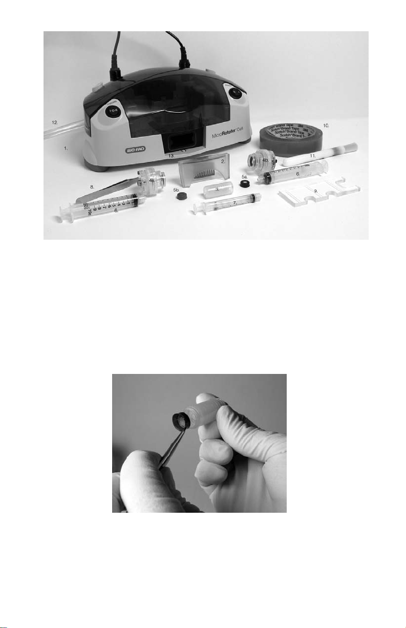
Fig. 1. MicroRotofor components and accessories. MicroRotofor chassis and lid (1),
harvesting tray (2), focusing chamber (3), anode assemb ly (4a), cathode assemb ly (4b), cathode
membrane, (5a), anode membrane, (5b), 10 ml syringes (6), 3 ml syringe (7), forceps (8),
assembly tool (9), sealing tape (10), cleaning brush (11), vacuum hose (12), vacuum chamber
(13).
1. Rinse the equilibrated ion exchange membranes with deionized water.
2. Insert an anode membrane assembly (red casing) into one end of the
focusing chamber and a cathode membrane assembly (black casing)
into the other end. (Figure 2)
Fig. 2. Inserting an anion exchange membrane into the focusing chamber.
3. Attach the electrode assemblies to the focusing chamber.
a. The anode assembly (red) is attached to the focusing chamber end
containing the anode membrane (red casing).
3
Page 6
b. The cathode assembly (black) is attached to the focusing chamber
end containing the cathode membrane (black casing).
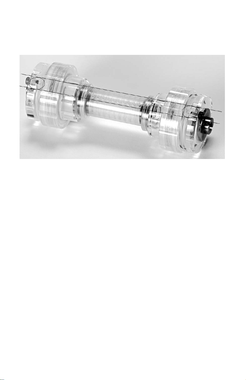
4. Align one row of focusing chamber ports with the vents on the electrode
assemblies.These are the sample loading ports. (Figure 3)
Fig. 3. Alignment of the sample loading ports with the vents on the anode (left) and
cathode (right) assemblies.
4.3 Prepare and Load the Protein Sample
Prepare the protein sample
The protein sample included in the starter kit contains three naturally colored
proteins in deionized water, Phycocyanin (pI range 4.5–5.5), Hemoglobin
(pI range 6.0–7.5), and Cytochrome c (pI range 8.0–9.0).Each protein is
present at a concentration of 2 mg/ml for a total protein concentration of
6 mg/ml.
Note: Vortex sample vial to homogenize material.
• To 100 µl of protein sample (600 µg total protein), add 150 µl Bio-lytes
pH 3-10, and 2.75 ml deionized water for a total volume of 3.0 ml.
Load the Protein Sample
The focusing chamber features two rows of ports.The row that is aligned
with the vents on the electrode assemblies will be used to load the sample
(loading ports).The row on the opposite side of the focusing chamber will be
used for harvesting the fractions (harvesting ports).The harvesting ports
must be sealed with tape before the sample is loaded.After the sample is
loaded, the loading ports will also be sealed with a piece of tape.
4
Page 7

1. Using the assembly tool as a template, cut two pieces of sealing tape
(Figure 4). Position the tape across the template covering all three
cutting grooves.Cut the tape with a cutting blade at all three grooves.
Each strip of tape can be picked up through the cutouts between two
grooves.
Fig. 4. Using the assembly tool to measure the appropriate length of sealing tape.
2. Seal the lower row of ports (harvesting ports) with a strip of tape. Make
sure to cover all of the ports, and to not extend the tape beyond the
focusing chamber (Figure 5).
Note: Excess tape, or tape not properly positioned, interferes with the
cooling block during oscillation, which can result in leakage of sample from
the focusing chamber.
Fig. 5. Applying sealing tape to cover the harvesting ports on the focusing chamber.
3. Fill the 3 ml syringe with sample.Slowly load the sample through the
centermost loading port of the focusing chamber (Figure 6). As this
channel fills, the sample will slowly spread to and fill all of the adjacent
channels.Continue adding sample slowly to this channel until all of the
channels are filled. Alternatively, fill every other channel and wait for the
sample to spread to the adjacent chambers.
Note: If air bubbles are introduced into the focusing chamber, the sample will
not spread to adjacent channels as described. Make sure to dislodge and
remove all air bubbles from the chamber by gently tapping or aspirating the
sample from a channel and loading it again.
5
Page 8

Fig. 6. Loading sample into the focusing chamber.
4. When the sample is loaded, make sure that all the channels are filled
and that no bubbles remain.Air bubbles will disrupt the electric field,
which can lead to poor separation.To dislodge air bubbles from the
chamber, tap it gently or aspirate the sample from a channel and load it
again.
5. Dry the outside surface of the focusing chamber and seal the row of
loading ports with a piece of the sealing tape. Make sure to cover all the
ports, to not extend the tape beyond the focusing chamber, and to not
overlap the tape with the strip of tape covering the harvesting ports.
Note: Excess tape, or tape not properly positioned, interferes with the
cooling block during oscillation, which can result in leakage of sample from
the focusing chamber.
4.4 Perform the Focusing Run
1. Open the cooling block cover by unscrewing the block screw.
2. With the sealed loading ports and vents on the electrode assemblies
facing up, place the focusing assembly into the focusing station of the
chassis.Make sure the anode end (red) is to the left and the cathode
end (black) is to the right.
I. Gently push the anode end (red) of the focusing assembly into the
anode connection on the chassis until it is completely retracted
(Figure 7).
II. Lower the focusing assembly into the cooling block and slide the
cathode end of the assembly into the notch on the cathode end of
the chassis (Figure 8). If necessary, rotate the focusing assembly
until the slots on the cathode assembly align with the notch on the
chassis.Alternatively, turn power on to the oscillating motor and wait
until the notch is in a better position to connect with the focusing
assembly.
6
Page 9

Fig. 7. Placing the focusing assembly Fig. 8. Fitting the cathode assembly into
onto the anode of the chassis. the cathode of the chassis.
3. Using a 10 ml syringe, add electrolyte solutions to the electrode
assemblies (Figure 9).
(Note:The electrode membrane storage solution from the starter kit can be
used. Alternatively fresh electrolyte solutions can be prepared)
I. Add 6 ml 0.1 M H3PO4through the vent hole of the anode assembly
(red).
II. Add 6 ml 0.1 M NaOH through the vent hole of the cathode
assembly (black).
Fig. 9. Adding electrolyte to the anode assembly.
4. Close the cooling block cover and tighten the screw.
5. Place the lid on the chassis.
6. Attach the power cord to the back of the MicroRotofor chassis and
connect it to an electrical outlet.
7. Connect the MicroRotofor cell to a vacuum source.We recommend
installation of a vacuum trap between the cell and the vacuum system.
7
Page 10

Note: Keep the vacuum valve closed until the run is completed and you are
ready for harvesting the fractions.
8. Turn the power switch to the “ON” position to start the oscillating motor.
9. Set the cooling switch to setting II (20°C).
(Note: See Table 3.2 in the MicroRotofor instruction manual, for detailed
cooling setting information.)
10.Attach the leads on the lid to a PowerPac HV power supply or other
commercial power supply capable of power control at 1 W. If your power
supply cannot be set to run under constant power, run the instrument in
a stepwise constant voltage mode with limiting current (see Section 4.5
for detailed power conditions.)
11.A typical run is completed in less than 3 hours.To monitor the focusing
progress, observe the voltage increase over time.The run is complete
when the voltage stabilizes.At that point, allow the run to continue for
30 minutes before harvesting.Longer run times do not improve focusing
and may result in a collapse of the pH gradient.
12.The progress of the run can also be monitored by following the migration
of the colored proteins in the sample.
Fig. 10. Migration of colored proteins.
• Phycocyanin has three blue subunits of pI 4.5, 4.7 and 5.0 that
migrate towards the anode and are expected to focus in fraction # 3.
• Hemoglobin A and Hemoglobin C, two red colored proteins of pI 7.1
and 7.4, respectively, migrate towards the center of the focusing
chamber and are expected to focus in fraction # 6 and/or #7.
• Cytochrome c, an orange protein of pI 9.6 migrates toward the
cathode and is expected to focus in fraction # 9 and/or 10.
8
Page 11

4.5 Power Conditions
Table 4.1 lists the recommended power conditions.
Power conditions are listed for power supplies capable of maintaining 1 Watt
constant power and for power supplies which cannot run under constant
power, but are programmable for stepwise constant voltage with limiting
current.
Note: Refer to the MicroRotofor instruction manual, Tables 3.2, 3.3, & 3.4 for
detailed power conditions and cooling setting information.
Table 4.1: Power conditions
4.6 Harvest the Fractions
Once the IEF run is complete, i.e., the colored proteins have focused in the
expected fractions, harvesting should be completed as quickly as possible to
avoid diffusion of the separated proteins.Throughout the following steps,
minimize movement of the focusing chamber to avoid diffusion.
1. Turn the power supply off and disconnect it from the MicroRotofor cell.
2. Turn off power to the oscillating motor and cooling block on the
MicroRotofor cell, and remove the lid from the chassis.
3. Make sure that the MicroRotofor chassis is connected to a vacuum
source and that the harvesting tray is in place and flush against the
sealing gasket.
4. Open the cooling block cover and, using forceps, remove the sealing
tape from the sample loading ports.
5. Apply a vacuum to the chassis.
Cooling Setting II:
Internal Temperature of 20 + 2°C at ambient temperature range
of 19–26°C
Constant Power
1 Watt
Step Method:
Constant Voltage
Voltage range
Step#. V / time
Current Range
1. 150V / 10 min.
8-3 mA
2. 200V / 10 min.
4-2 mA
3. 300V / 60+ min.
4-3 mA
100–500 V
A 20mA current limit and a 2W power
limit are recommended for the Step
Method.
9
Page 12

6. Remove the focusing assembly from the running station. First, push
focusing assembly towards anode to dislodge the connector from the
cathode notch in the chassis.Then lift up gently on the cathode end and
remove the anode end (red).
7. With the row of sample loading ports facing up (sealing tape on loading
ports removed), position the focusing assembly in the harvesting station
(Figure 10).Two sides of the focusing chamber are flattened to correctly
orient the focusing assembly within the harvesting station and to help
align the harvesting needle array with the sealed harvesting ports of the
focusing chamber. DO NOT puncture the sealing tape covering the
harvesting ports.
Fig. 11. Placement of the focusing assembly into the harvesting station.
8. Taking care to not cover any of the loading ports with your fingers, and
using both hands, press down evenly and firmly on the electrode
assemblies so that all the needles penetrate the sealing tape and
harvesting ports simultaneously.At the same time and using the thumbs
of both hands, press the harvesting tray against the seal of the vacuum
assembly (Figure 12).
10
Page 13

Fig. 12. Harvesting the fractions.
9. Continue to press down on the focusing chamber for several seconds to
aspirate the ten fractions into the harvesting tray.
10.Remove the harvesting tray and turn off the vacuum source.
11.Transfer the fractions to micro tubes or other containers with a syringe or
pipet (Figure 13).
Fig. 13.Transferring the fractions.
11
Page 14

Section 5
Disassembly and Cleaning
5.1 Focusing Assembly
1. Using the assembly tool, loosen and remove the electrode assemblies
from the focusing chamber (Figure 14).
Fig. 14. Using the assembly tool to remove the anode assembly from the focusing
assembly.
2. Using the forceps, remove the ion exchange membranes from the
focusing chamber and immediately store them in deionized water or in
their respective electrolyte solution.
Note:The membranes cannot be allowed to dry out after they have been
equilibrated.The membranes may be stored in electrolyte or in distilled water
between runs.If they dry out, the membranes may crack and cause leakage
of electrolyte into the focusing chamber. Equilibrated membranes, if stored
properly, can be reused for 4–5 runs.
3. Rinse the electrode assemblies with deionized water.
4. Wash the focusing chamber.Place the focusing chamber in 2% SDS
solution overnight.Thoroughly rinse the focusing chamber with deionized
H2O to remove the SDS.
5.2 Harvesting Station
To maintain optimal harvesting performance, it is critical to wash the needle
array immediately after harvesting is complete.The entire harvesting station
and needle array may be detached from the chassis, washed with a mild
detergent, and rinsed with deionized water.
1. Disconnect the chassis from the vacuum source.
12
Page 15

2. Remove the two screws that secure the Harvesting station to the vacuum
block and remove the positioning block, needle array, and needle array
holder (Figure 15).
Fig. 15. Disassembling the harvesting station (top) and harvesting station components
(bottom).
3. Clean and dry the positioning block.
4. Using a wash bottle, wash and rinse the individual needles in the needle
array.
5. Clean and dry the vacuum chamber.
6. Inspect and reposition the vacuum gaskets.
7. Reassemble the harvesting station.
13
Page 16

Note: For additional information on analysis of results, optimizing protein
separation, and troubleshooting, please refer to the MicroRotofor instruction
manual.
Appendix A
Product information
Catalog # Description
170-2800 MicroRotofor Cell Kit, 100/120 V
170-2801 MicroRotofor Cell Kit, 220/240 V
170-2802 MicroRotofor System, 100/120 V, includes kit with
PowerPac HV power supply
170-2803 MicroRotofor System, 220/240 V, includes kit with
PowerPac HV power supply
170-2804 MicroRotofor Starter Kit
170-2810 MicroRotofor Harvesting Trays,3
170-2820 MicroRotofor Sealing Film, harvesting tray sealing film,
10 sheets
170-2960 MicroRotofor Sealing Film, focusing chamber port
sealing tape, 1 roll
170-2821 MicroRotofor Focusing Chambers,3
170-2822 MicroRotofor Cathode Assembly, 1
170-2826 MicroRotofor Electrode Assembly Gasket Kit, (electrode
buffer chamber o-ring and gaskets)
170-2829 MicroRotofor Anode Assembly, 1
170-2832 MicroRotofor Assembly Tool
170-2833 MicroRotofor Ion Exchange Membrane Assemblies
170-2835 MicroRotofor Cleaning Brush
170-2836 MicroRotofor Syringes, 3 x 3 ml and 3 x 10 ml
170-2850 MicroRotofor Harvesting Station, alignment station,
needle assembly and needle holder
170-2851 MicroRotofor Needle Assembly
170-2852 MicroRotofor Vacuum Block O-Ring
170-2855 MicroRotofor Lid
165-5056 PowerPac HV Power Supply and Accessories,
100–120 V/220–240 V
14
Page 17

10004399 Rev A
Bio-Rad
Laboratories, Inc.
Life Science
Group
Web site www.bio-rad.com USA (800) 4BIORAD Australia 02 9914 2800
Austria (01)-877 89 01 Belgium 09-385 55 11 Brazil 55 21 2527 3454
Canada (905) 712-2771 China (86 21) 6426 0808
Czech Republic + 420 2 41 43 05 32 Denmark 44 52 10 00
Finland 09 804 22 00 France 01 47 95 69 65 Germany 089 318 84-0
Greece 30 210 777 4396 Hong Kong (852) 2789 3300
Hungary 36 1 455 8800 India (91-124)-2398112/3/4, 5018111, 6450092/93
Israel 03 951 4127 Italy 39 02 216091 Japan 03-5811-6270
Korea 82-2-3473-4460 Latin America 305-894-5950
Mexico 55-52-00-05-20 The Netherlands 0318-540666
New Zealand 64 9 415 2280 Norway 23 38 41 30
Poland + 48 22 331 99 99 Portugal 351-21-472-7700
Russia 7 095 721 1404 Singapore 65-64153188
South Africa 00 27 11 4428508 Spain 34 91 590 52 00
Sweden 08 555 12700 Switzerland 061 717 95 55
Taiwan (886 2) 2578 7189/2578 7241 United Kingdom 020 8328 2000
Sig 1204
 Loading...