

Page 1
Model EG-1
Econo Gradient
Monitor
Instruction
Manual
Catalog Numbers
731-8151
731-8150
Page 2

Warranty
Model _________________________________________
Serial Number __________________________________
Date of Delivery_________________________________
Warranty Period _________________________________
Unless otherwise specified, instruments sold by Bio-Rad are under
warranty for 1 year against defects in materials and workmanship.
If any defects should occur during this warranty period, Bio-Rad will
replace the defective parts without charge. However, the following defects
are specifically excluded:
1. Damage caused by improper operation.
2. Repair or modification done by anyone other than Bio-Rad
Laboratories or their authorized agent.
3. Deliberate or accidental misuse.
4. Damage caused by disaster.
5. Damage due to use of improper solvent or sample.
6. Damage due to spills.
This warranty does not apply to fittings, tubing, and fuses.
For inquiry or to request repair service, contact Bio-Rad Laboratories
after confirming the model and serial number of your instrument.
For Technical Service, call your local Bio-Rad Office or, in the U.S.,
call 1-800-4BIORAD (1-800-424-6723).
Page 3

Table of Contents
Section 1 Safety ............................................................................. 1
Section 2 Introduction.................................................................. 2
Section 3 Unpacking ..................................................................... 3
Section 4 Description and Features............................................ 4
4.1 Front Panel Functions ............................................................. 4
4.2 Rear Panel Sockets................................................................. 6
4.3 Flow Cell ................................................................................ 7
Section 5 Setting Up ..................................................................... 7
5.1 Flow Cell Installation............................................................. 7
5.2 Connecting the Model EG-1 Econo Gradient
Monitor to Recording Equipment........................................... 7
Section 6 General Operation....................................................... 8
6.1 Conductivity Mode................................................................. 9
6.2 Gradient Mode........................................................................ 9
Section 7 Care and Maintenance................................................ 10
Section 8 Troubleshooting............................................................ 11
Appendix A Fuse Replacement ........................................................ 13
Appendix B Rear Panel Connections .............................................. 13
Appendix C Technical Specifications............................................... 14
Appendix D Ordering Information.................................................. 15
Page 4

Section 1
!
Safety
Disconnect supply before servicing. No user serviceable parts inside.
Refer servicing to Bio-Rad service personnel.
This instrument is intended for laboratory use only.
This product conforms to the “Class A” standards for electromagnetic
emissions intended for laboratory equipment applications. It is possible
that emissions from this product may interfere with some sensitive
appliances when placed nearby or in the same circuit as those appliances. The user should be aware of this potential and take appropriate
measures to avoid interference.
1
Page 5
Section 2
Introduction
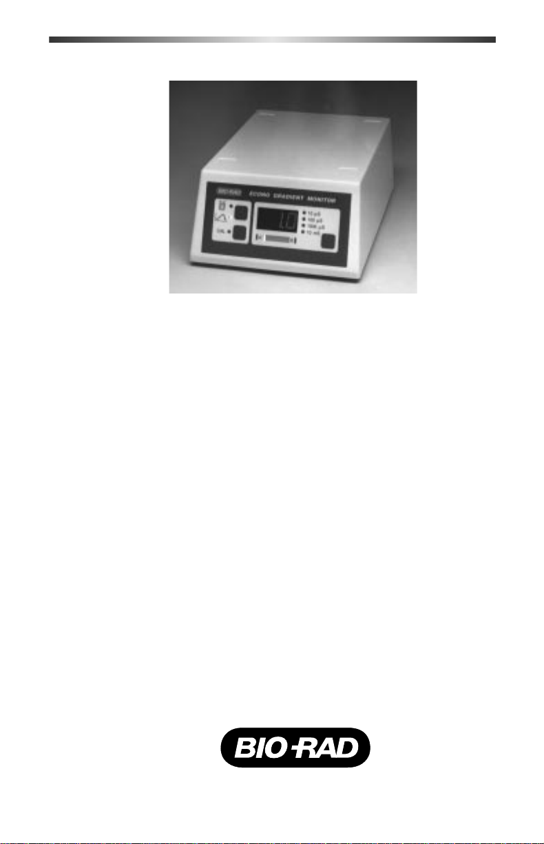
Fig. 1.1. Model EG-1 Econo Gradient Monitor.
The Model EG-1 Econo Gradient Monitor is a high quality, easy to use,
conductivity and gradient monitor for liquid chromatography. The monitor
consists of a control unit and an external flow cell. The flow cell is fitted
with luer connectors for rapid tubing connections. It can be connected to
the outlet of an Econo-Column®chromatography column or an Econo-Pac
Cartridge.
®
In the Conductivity mode, the Econo Gradient Monitor functions as a
standard conductivity monitor with numerical output in Siemens*. In the
Gradient mode, gradient end-points (e.g. buffer A and buffer B) can be
programmed, relative gradient progress is displayed on the Bar Graph,
numerical output is displayed in Siemens, and full scale output to a chart
recorder is automatically adjusted.
The Model EG-1 Econo Gradient Monitor functions as a stand-alone
instrument or as an integral part of any chromatography system.
For technical specifications, refer to Appendix C.
*1 Siemen = 1 Mho = 1/Ohm
2
Page 6
Section 3
Unpacking
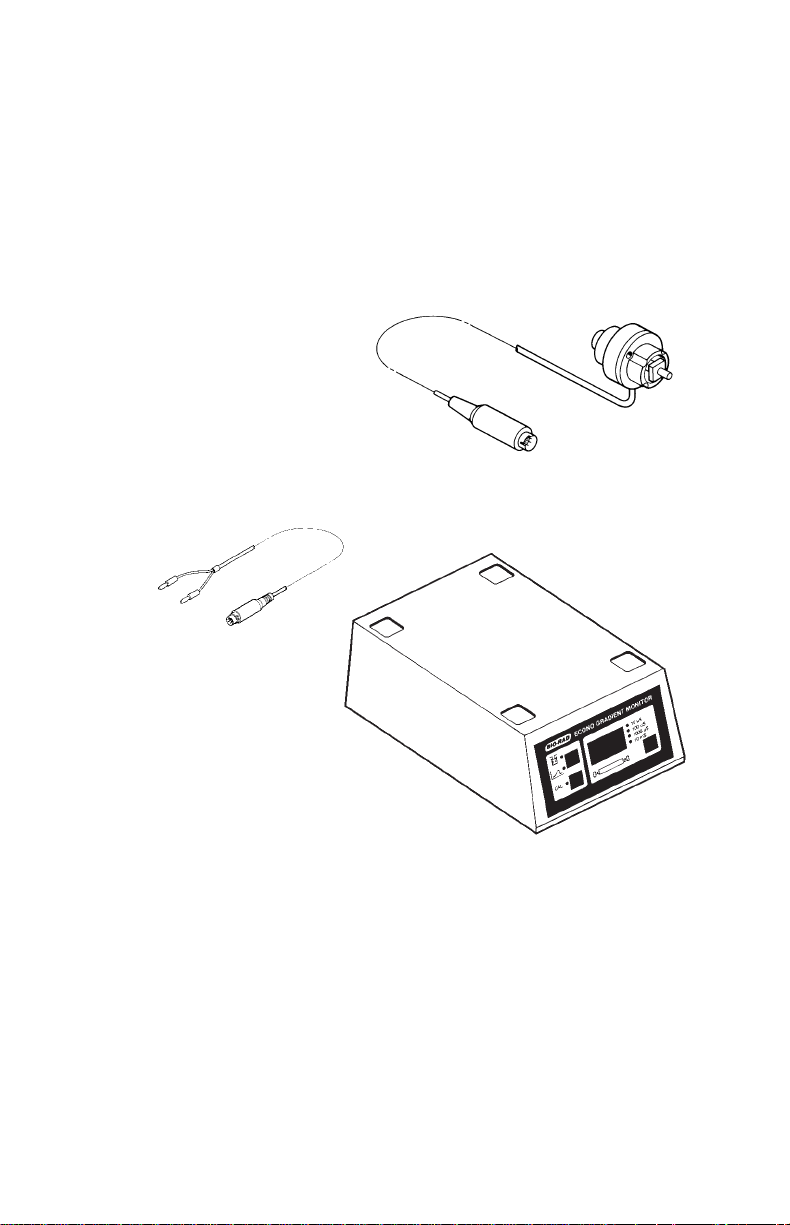
Carefully remove the contents of the shipping box, and check for any
obvious damage or problems with the instrument. Figure 2.1 shows the
parts included with the Model EG-1 Econo Gradient Monitor. Check of f all
parts against the supplied packing list.
If any parts are missing or damaged, contact Bio-Rad Laboratories
immediately.
Flow Cell
Cable 4
Control Unit
Also includes: Instruction Manual, 3 male luer fittings and 3 female luer fittings.
Fig. 2.1. Parts supplied with the Model EG-1 Econo Gradient Monitor.
Note: The Model EG-1 Econo Gradient Monitor requires a power
adaptor. If you did not receive one, contact your local Bio-Rad
representative.
3
Page 7

Section 4
Description and Features
The Model EG-1 Econo Gradient Monitor consists of a control unit and
a flow cell. The control unit houses the electronics and user interface. The
flow cell connects to the control unit and is external for flexible placement.
The following tables and illustrations describe the features of the
Model EG-1 Econo Gradient Monitor.
4.1 Front Panel Functions
Fig. 3.1. Front panel controls.
Display Function
Range Selector In the Conductivity mode, the
Range Selector allows the user to
select one of four range settings
between 10 micro-Siemens
and 10 milli-Siemens full scale.
The strip chart recorder output
will be scaled accordingly.
3-Digit Display The 3-digit display shows con-
ductivity in Siemens, in accordance with the range selected.
4
Page 8

Display Function
Bar Graph In the Conductivity mode, the Bar
Graph provides a graphic representation of the buffer conductivity relative to the lower and upper
limits of the selected range. In the
Gradient mode, the Bar Graph
provides an indication of the
buffer conductivity relative to
buffer A and B. Aflashing red
LED at either end of the Bar
Graph indicates an out of range
condition.
Mode Selector Allows selection of Conductivity
or Gradient mode.
Gradient For use only in the Gradient
Calibration mode. The Gradient Calibration
key activates a routine which
allows the user to enter conductivity values for buffer A and
buffer B by passing the desired
“A” and “B” solutions through
the flow cell. The values for A
and B are automatically established as “0” and 100% full scale
and chart recorder output is
scaled accordingly.
5
Page 9

4.2 Rear Panel Sockets
Fig. 3.2. Rear panel sockets.
The rear panel of the Model EG-1 Econo Gradient Monitor control unit
contains an On/Off power switch and four sockets for electrical
connections (see Figure 3.2). Abrief description of each socket follows.
Display Function
Power Entry For connection of the 12 VDC
power adaptor.
Signal Output For connection of chart recorders,
Socket integrators and computers to the
Model EG-1 Econo Gradient
Monitor using standard Bio-Rad
cables. See Section 4.2 and
Appendix B.
Flow Cell For connection of the flow cell’s
Socket Signal Cable.
Remote Socket This feature is not implemented
in the Model EG-1.
6
Page 10

4.3 Flow Cell
Fig. 3.3. The flow cell.
Inlet/Outlet Ports A male and a female luer fitting on either end of the
Signal Cable For connection of the flow cell to the socket on
Section 5
Setting Up
flow cell allow rapid tubing connection. The flow
cell can be used with flow in either direction. Note:
the luer fittings may be unscrewed and replaced with
1/4”-28 threaded flat-bottom fittings.
the rear panel of the control unit.
5.1 Flow Cell Installation
Place the flow cell as close as possible to the column outlet and/or any
other detection devices (e.g. a UV flow cell, if used) and connect the flow
cell’s Signal Cable to the flow cell socket on the rear panel of the
control unit.
If the monitor is to be used in conjunction with the Model EM-1
Econo UV Monitor, connect the gradient monitor flow cell directly to the
inlet or outlet port of the portable optics module for optimal detection.
If the Econo Gradient Monitor is to be used with other UV monitors, the
flow cell should be placed as close as possible to the UV detection device.
5.2 Connecting the Model EG-1 Econo Gradient
Monitor to Recording Equipment
The Model EG-1 Econo Gradient Monitor is shipped with System
Cable 4, which connects the Econo Gradient Monitor to channel 2 of the
7
Page 11

Model 1327 Econo Recorder. The cable also connects the Econo Gradient
Monitor to other recording devices which use banana plug connectors.
Connecting the Model EG-1 Econo Gradient Monitor to a
Model 1327 (dual pen) Econo Recorder
The Model EG-1 Econo Gradient Monitor must be connected to channel 2 of the Model 1327 Econo Recorder. Use System Cable 4 to connect
the Econo Gradient Monitor to the banana plug signal inputs on the rear
panel of the Econo Recorder. Plug the 8-pin mini-DIN end of cable 4 to
the socket on the rear panel of the Econo Gradient Monitor. Insert the
black banana plug into the ground input and the red banana plug into
the voltage input for channel 2 of the Model 1327 Econo Recorder.
Connecting the Model EG-1 Econo Gradient Monitor to Other
Chart Recorders
Use System Cable 4 to connect the Model EG-1 Econo Gradient
Monitor to recording devices which accept banana plugs. Insert the 8-pin
connector into the signal output socket on the rear panel of the Model
EG-1 Econo Gradient Monitor. At the other end of the cable are two
banana plugs. The red plug is the positive output, and the black plug is the
negative, or ground. These plugs should fit directly into the input sockets
of most chart recorders.
The signal output socket on the rear panel of the Model EG-1
Econo Gradient Monitor is an 8-pin circular mini-DIN and is intended for
use with Econo System components. For those wishing to interface the
Model EG-1 Econo Gradient Monitor with equipment such as integrators
or chart recorders which do not utilize banana plug connectors, System
Cable 7 (available separately) may be used. System Cable 7 has an 8-pin
mini-DIN at one end, for connection to the Model EG-1 Econo Gradient
Monitor, and loose wires at the other. See Appendix B for the pin configuration of the 8-pin mini-DIN signal output socket.
Section 6
General Operation
1. Make sure all the electrical connections and
plumbing have been done properly (See Section 4).
Allow the monitor to warm up for approximately
10 minutes.
2. The Econo Gradient Monitor powers up in either
the Conductivity mode or the Gradient mode. Use
the Mode Selector key to select the desired mode.
8
Page 12

6.1 Conductivity Mode
In the Conductivity mode, the numerical LED displays the conductivity (in Siemens) of the solution in the flow cell, and the LED indicator
light indicates the range selected. The Bar Graph gives an
indication of the conductivity relative to the range setting currently chosen
(thereby giving an indication of the relative position of the chart recorder
pen).
1. Press the Range Selector key to select a range
which will include the expected maximum conductivity of the solutions to be used.
2. If the monitor is connected to a strip chart
recorder, set the recorder range to 1 V. The full
scale reading on the recorder corresponds to the
selected range setting on the monitor.
An out of range condition is indicated by a flashing numerical “999”
display and flashing red LED’s at either end of the Bar Graph.
6.2 Gradient Mode
In the Gradient mode, the numerical LED displays the conductivity (in Siemens) of the solution in the flow cell. The range is automatically
determined based on the conductivity values for buffers A and B (entered
during calibration). Full scale output to a chart recorder or integrator is
adjusted automatically, assuring the gradient trace will not move of f the top
of the chart paper. Once the gradient monitor is calibrated, the Bar Graph
will indicate buffer conductivity relative to the conductivity
values for buffer A and B.
Calibrating Gradient End Points
The gradient monitor should be calibrated every time the buffers are
changed, if a new batch of buffers is prepared, or if the buffers are one day
or more old.
1. Press the CAL key once. The gradient mode, “A”
LED, and CAL indicator lights will flash.
2. Pass buffer Athrough the flow cell using a pump or
syringe until the conductivity reading stabilizes. (A
flashing CAL indicates the monitor is calibrating.)
3. Press the CAL key to accept the conductivity value
for buffer A. The gradient mode, “B” and CAL
indicator lights will immediately begin to flash.
9
Page 13

4. Pass buffer B through the flow cell until the conductivity reading stabilizes. (A flashing CAL indicates the monitor is calibrating.)
5. Press the CAL key to accept the conductivity
value for buffer B.
Note: If the 3-digit display reads “Err”, the conduc-
tivity valves for buffer A and B are too close
together to use the Gradient mode. Press the
and use the Conductivity mode.
When steps 1-5 above are complete, the Bar Graph will
indicate the buffer conductivity in the flow cell relative to the conductivity
values set for buffer A and B. The gradient monitor output is automatically
calibrated to 0 to 1 V based on the values set for buffer A and B. (Insure
that the recorder input is set to 1V full scale.)
If the conductivity of the buffer in the flow cell falls outside the values
set for buffers A and B, a red indicator light will appear on the Bar Graph.
Section 7
Care and Maintenance
Mode Selector key to cancel calibration
The Model EG-1 Econo Gradient Monitor requires very little maintenance to assure reliable operation. Following are general procedures for
maintenance of the control unit and flow cell.
10
Page 14

Model EG-1 Econo Gradient Monitor Control Unit and Flow Cell:
The control unit may be left on continually (power consumption is negligible).
Although the cases are chemical resistant, spills and splashes may
cause precipitates to form on the component cases. Use a squirt bottle
and soapy water to wash down the outer cases of the instrument.
Flow Cell
Clean the outside surface of the flow cell as described above.
The flow cell should be cleaned periodically with 1 M NaOH at 1
ml/min for 5 min. (SDS, 1 M HCl, 1 M NaOH, EtOH, and acetone will
not harm the Model EG-1 Econo Gradient Monitor flow cell.)
When the flow cell is not in use, disconnect, and clean out dissolved
salts using a syringe filled with deionized water.
Store the flow cell by injecting a dilute solution (15-25%) of ethanol or
isopropanol into the cell to prevent microbial growth. Use the end caps
provided to seal the flow cell’s inlet and outlet ports. Always rinse the
flow cell with water prior to the introduction of aqueous buffers. To
prevent the formation of salt crystals and solute deposits, do not allow
the flow cell to dry out.
Section 8
Troubleshooting
Problem Possible Cause Solution
Baseline drift or Bubbles in flow cell Use degassed buffers.
noisy signal Check for loose plumb-
ing connections
Dirty flow cell Clean flow cell; insure
that buffers are free of
particulate material
(See Section 6)
Bubbles passing Use degassed buffers.
through flow cell Check for loose plumb-
ing connections
Column not Equilibrate and/or
equilibrated or dirty regenerate column
11
Page 15

Problem Possible Cause Solution
Larger or smaller than Chart recorder input Check chart recorder
expected gradient voltage set incorrectly settings (See Sections
profile 4.2 and 5)
If using Gradient Re-calibrate the
mode, buffer A and gradient mode
B values not set
correctly
Ghost peaks appear in Charged sample No problem
gradient profile detected (e.g. protein)
Air bubbles passing Use degassed buffers.
through flow cell Check for loose plumb-
ing connections
Chart recorder Chart recorder is not Check connections (See
not responding connected properly Sections 3.2 and 4.2)
Full scale of recorder Set recorder range to
set too high 1 V
Recorder has bottomed Readjust pen position
out
Flow cell not Check flow cell
connected in-line plumbing
No power Faulty power Check power cable
connection connection
Blown fuse Check fuses (See
Appendix A)
Unit not switched on Check power on/off
switch on rear panel
Conductivity Dirty flow cell Clean flow cell (See
measurements with Section 6)
same buffer appear
to decrease over time
12
Page 16
Appendix A
Fuse Replacement
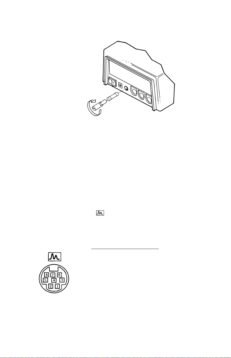
Figure A. Fuse removal.
1. Disconnect unit from power source.
2. Remove the fuse cover with a small-blade screwdriver or similar tool.
3. Pull the fuse holder out of the fuse compartment and, if necessary,
replace the fuse. Use 5 mm x 20 mm fuse, type T, 1A.
4. Reinsert the fuse holder, with fuse, into the fuse compartment.
Appendix B
Rear Panel Connections
The signal output socket is an 8-pin circular mini-DIN. The fol-
lowing information is provided for those wishing to interface the Model
EG-1 Econo Gradient Monitor with equipment such as integrators or chart
recorders which do not utilize banana plug connectors.
Pin Function
1 No Contact
2 No Contact
3 No Contact
4 No Contact
5 Chart Recorder (+)
6 Chart Recorder (-)
Pin configuration
7 No Contact
8 No Contact
13
Page 17

Appendix C
Technical Specifications
General
Operating mode Conductivity, in units of Siemens (See
Operating temperature 4-40 °C
Sensitivity ranges (full scale) 0-10µS, 0-100µ S, 0-1000µS, 0-10mS
Output signal 0-1 Volt
Power requirements 90-264 V, 50-60 Hz (depending upon
Power consumption 20W maximum
Noise Short Term: < 0.1 µ S
Linearity +/-0.5 % full scale
Accuracy +/-2 % full scale
Drift < 0.5 µ S/hour/°C
Dimensions
Control Unit: 15.60 x 22.86 x 8.89 cm (W x L x H)
Flow Cell: 3.1 cm diameter by 3.8 cm length
Weight Control Unit: 600g
Case Material Chemical and fire resistant polypropylene
Regulatory CSA: C22.2 No. 151-M1986
Compliance: TÜV: EN61010-1:1993
Section 1)
power adaptor used)
Long Term: < 0.5 µ S
CE: EN55011: 1991 Class A
EN50082-2:1995
Flow cell
Type Flow through, externally mounted
Temperature compensation 0-60 °C
Internal volume 8 µl, swept volume
Cell constant Approximately 40*
Maximum operating pressure 60 psi, 4 bar, or 0.41 mPa
Cable length 1.22 M
Wetted Parts Titanium, Kel-F and Tefzel
Fittings Removable luer (Will also accept 1/4”-28
flat bottom fittings)
* Most applications do not require an exact cell constant. If it is necessary
to determine the exact cell constant, Bio-Rad‘s Conductivity Standard,
catalog number 167-0445, can be used.
14
Page 18

Appendix D
Ordering Information
Model EG-1 Econo Gradient Monitor
731-8151 Econo Gradient Monitor, Model EG-1, with 100-120 V
power adaptor (catalog number 731-8270) and flow cell
(catalog number 731-8155)
731-8150 Econo Gradient Monitor, Model EG-1, requires power
adaptor, includes flow cell (catalog number 731-8155)
731-8155 Flow Cell, Model EG-1, 1 cell
731-8270 Power Adaptor, 100-120 V, for USA, Canada, Japan,
Mexico, Taiwan, Latin America
731-8271 Power Adaptor, 220-240 V, for Europe (except the UK)
and other countries not specifically listed
731-8272 Power Adaptor, 220-240 V, for UK, Australia, New
Zealand
Cables
731-8264 System Cable 4, 8-pin mini-DIN to banana plugs (for con-
nection of Econo Gradient Monitor to Model 1327
Recorder or other recording devices which accept banana
plug connectors)
731-8267 System Cable 7, 8-pin mini-DIN to breakout, for connec-
tion of Econo Gradient Monitor to recording devices which
do not use banana plug connectors.
Tubing
731-8210 Silicone Tubing, 0.8 mm ID, 0.8 mm wall, 10 m
731-8211 Silicone Tubing, 1.6 mm ID, 0.8 mm wall, 10 m
731-8212 Silicone Tubing, 3.2 mm ID, 0.8 mm wall, 10 m
731-8214 Tygon Tubing, 0.8 mm ID, 0.8 mm wall, 10 m
731-8215 Tygon Tubing, 1.6 mm ID, 0.8 mm wall, 10 m
731-8207 PharMed®Tubing, 0.8 mm ID, 1.0 mm wall, 10 m
731-8208 PharMed Tubing, 1.6 mm ID, 1.0 mm wall, 10 m
731-8209 PharMed Tubing, 3.2 mm ID, 1.0 mm wall, 10 m
Fittings
731-8220 Low Pressure Fittings Kit, includes over 17 different fit-
tings and stopcocks (250 fittings total)
Tygon and PharMed are registered trademarks of the Norton Company.
15
Page 19

Life Science
Group
Web site www.bio-rad.com USA (800) 4BIORAD Australia 02 9914 2800
Austria (01) 877 89 01 Belgium 09-385 55 11 Brazil 55 21 507 6191
Canada (905) 712-2771 China 86-10-8201-1366/68 Denmark 45 44 52-1000
Finland 358 (0)9 804 2200 France 01 47 95 69 65 Germany 089 318 84-177
Hong Kong 852-2789-3300 India (91-124) 6398112/113/114 Israel 03 951 4124
Italy 34 91 590 5200 Japan 03-5811-6270 Korea 82-2-3473-4460
Latin America 305-894-5950 Mexico 52 5 534 2552 to 54
The Netherlands 0318-540666 New Zealand 64-9-4152280 Norway 47-23-38-41-30
Russia 7 095 979 98 00 Singapore 65-2729877 Spain 34-91-590-5200
Sweden 46 (0)8-55 51 27 00 Switzerland 061-717-9555 United Kingdom 0800-181134
00-000 0000 Sig 1200Bulletin 0000 US/EG Rev A
Bio-Rad
Laboratories
M7318150 Rev H
 Loading...