

Page 1
Econo System
Instruction
Manual
For
Technical Service
Call Your Local Bio-Rad Office
in the U.S.
t=it•J;1
Calll-800-4BIORAD
( 1-800-424-6723)
9
•)
or
Page 2
Warranty
Model
Serial Number
Date
Warranty Period
Unless otherwise specified, instruments sold by Bio-Rad Laboratories are
warranted for 1 year against defects in materials and workmanship.
If
replace the defective parts without charge. However, the following defects are
specifically excluded:
1.
Defects caused by improper operation.
2.
Repair or modification done by anyone other than Bio-Rad Laboratories
or an authorized agent.
3.
Use with tubings or fittings not specified by Bio-Rad Laboratories for use
with this system.
4. Deliberate
_______________
______________
of
Delivery
any defects should occur during this warranty period, Bio-Rad will
or
-------------
____________
accidental misuse.
_
_
_
5.
Damage caused by disaster.
6.
Damage due to use
7. Damage due to spills.
This warranty does not apply to tubing, fittings, and fuses.
For inquiry or request for repair service, contact Bio-Rad Laboratories after
confirming the model and serial number
For Technical
Call l-800-4BIORAD (1-800-424-6723)
of
improper solvents or samples.
of
your instrument.
Service Call Your Local Bio-Rad Office
or
in the U.S.
Page 3
Table
of
Contents
Section 1
1.1
1.2
Section2
2.1
2.2
2.3
Section 3
3.1
3.2
3.3
Section 4
4.1
4.2
4.3
4.4
4.5
4.6
4.7
4.8
4.9
4.10
Introduction .................................................................. .
Overview ................................................................................. .
System Components ................................................................ .
Unpacking the Econo System Controller ................... .
Unpacking Instructions ........................................................... .
Voltage Considerations ............................................................ .
Safety Considerations .............................................................. .
1
1
2
3
3
4
5
Econo System Controller:
Physical Description and Control Features ............... .
Front Panel Functions .............................................................. .
Rear
Panel Functions ............................................................... .
Topside Functions .................................................................... .
6
6
7
8
Econo System Controller Connections and Set Up .... 9
Model EP-1 Econo Pump......................................................... 10
Model EM-1 Econo UV Monitor and Optics Module.............
Model
and Model
Model EG-1 Econo Gradient Monitor . . . .... ... . . ...
Model
Model
Solvent Reservoir.....................................................................
Model 1325 Econo (Single-pen) Recorder...............................
Model 1327 Econo (Dual-pen) Recorder.................................
Data Aquisition Systems ............................ .............................. 14
EV-1
2110 Fraction Collector
SV-3
Econo Buffer Selector
SV-5
Valve Pod......................................................
Diverter Valve......................................................
..
. . ...
...
. .......
..
. .
.. ..
...
. .
...
. . ... . .
.....
..
. . .... ...... ... 12
..
11
12
. . . . . 12
13
13
13
13
Section 5
5.1
5.2
5.3
5.4
5.5
5.6
5.7
5.8
Section 6
6.1
6.2
Plumbing the System..................................................... 14
Tubing and Fittings . .
Gradient Proportioning Valve and Mixer................................. 16
Model
Model
Manual Sample Injection Valve
and Chromatography Column . . . ... . .
UV Optics Module and Gradient Monitor Flow Cell . . . .
Model
Fraction Collector.....................................................................
EP-1 Econo Pump......................................................... 16
SV-5
Valve Pod.............................................................
SV-3
Diverter Valve ......................................................
..
... . . . . ..... ..... ... . .........
... . ..
.. . ..
. ........ ...........
. . ..... ... . .
.. . ..
..
.. . ..
. . .
..
. . ...
15
17
.. . .. . .. . 18
.. . .. ..
... 20
21
21
Getting Started .............................................................. 21
Connecting System to Power
System Check........................................................................... 22
..
. . . ..... ... . . ... ...... ....
..
..
. . .
..
......
...
..
...
21
Page 4

Section 7
7.1
7.2
7.3
7.4
7.5
7.6
7.7
7.8
7.9
Programming the System .............................................
Getting Started:
Verification
Econo
!socratic (Single Buffer) Methods............................................
Binary Gradient Formation . ... . . . . .
Peak Detection and Collection .....
Programming Multi-Step Methods
(Using the Econo Buffer Selector)........................................... 35
Programming Multi-Step Methods Which Include a Binary
Gradient (Using the Econo Buffer Selector)............................ 38
Programming Automated
Options While Running A Method . . ..... ...
of
Econo System Software Version...................... 23
System Software Mode Selection................................. 24
..
. .
...
. .....
...
. . ...
..
... . ... . . . .... ...
.. . ...
......
..
..
......
...
..
... ....... ....
Sample Injection............................. 39
..
.... ... . . .... ... . . .
..
. . .
..
..
. .
...
...
..
23
25
28
31
40
Section 8
Section 9
Appendix A
Appendix B
Appendix C
Storage and Maintenance............................................. 42
Thoubleshooting ............................................................. 43
Interfacing and Signals .................................................
45
System Specifications .................................................... 47
Ordering Information................................................... 48
Page 5
Section
1
Introduction
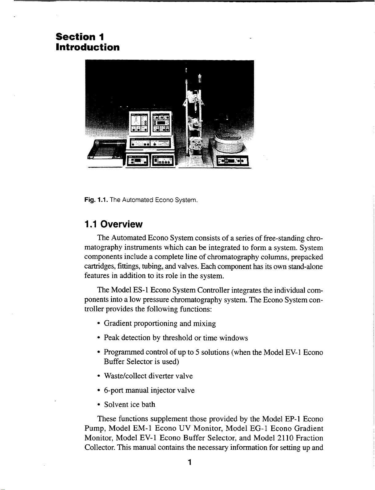
Fig. 1.1. The Automated Econo System.
1.1
Overview
The Automated Econo System consists
matography instruments which can be integrated to form a system. System
components include a complete line
cartridges, fittings, tubing, and valves. Each component has its own stand-alone
features in addition to its role in the system.
The Model ES-1 Econo System Controller integrates the individual com-
ponents into a low pressure chromatography system. The Econo System con-
troller provides the following functions:
• Gradient proportioning and mixing
• Peak detection by threshold
• Programmed control
Buffer Selector is used)
• Waste/collect diverter valve
• 6-port manual injector valve
of
up to 5 solutions (when the Model
of
or
time windows
of
a series
chromatography columns, prepacked
of
free-standing chro-
EV-1
Econo
• Solvent ice bath
These functions supplement those provided by the Model EP-1 Econo
Pump, Model EM-1
Monitor, Model EV-1 Econo Buffer Selector, and Model
Collector. This manual contains the necessary information for setting up and
Econo
UV
Monitor, Model EG-1 Econo Gradient
2110 Fraction
1
Page 6
running the system. In some sections, references will be made to informati1
provided in the component manuals. A binder is provided to help organi
the information.
1.2 System Components
The complete Automated Econo System consists
ponents:
• Model EP-1 Econo Pump
• Model EM
• Model ES-1 Econo System Controller
• Model
• Model EG-1 Econo Gradient Monitor
• Model 2110 Fraction Collector (optional)
• Econo Rack
• Econo System Organizer
• Model SV-3 Diverter Valve
• Model MV-6 6-port Injection Valve
• Model 1325 Econo Recorder (optional)
-1
Econo UV Monitor
EV-1
Econo Buffer Selector
of
the following com-
•
Modell327
The standard Econo System consists
• Model EP-1 Econo Pump
• Model EM-1 Econo UV Monitor
• Model ES-1 Econo System Controller
•
Model2110
• Econo Rack
• Model SV-3 Diverter Valve
• Model MV-6 6-port Injection Valve
• Model 1325 Econo Recorder (optional)
For the Econo System controller to function, it must be connected to the
Model EP-1 Econo Pump. For automated control
Model EV-1 Econo Buffer Selector must be connected to the Econo
controller. Aside from these requirements, UV and gradient monitors, frac-
Econo (Dual-Pen) Recorder (optional)
of
the following components:
Fraction Collector (optional)
of
more than 2 buffers, the
System
2
Page 7
tion collectors, and chart recorders from other manufacturers can
with the system.
See Appendix A for details.
_Section 2
.~_)npacking
2.1
Unpacking Instructions
Start by removing the solvent bath, which contains the tubing, fittings kit,
and sample injection valve. Next, remove the system controller, by lifting under
of
the base
the plastic bag, and
instrument.
cables, injector valve, and diverter valve. Figure
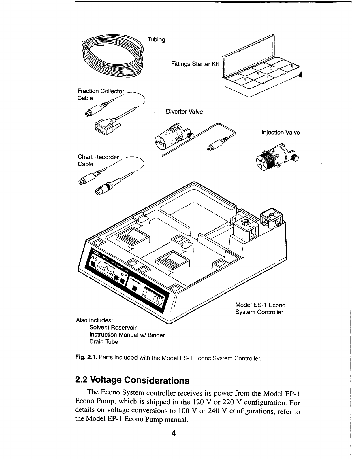
included with the Econo System controller. Check off all parts against the supplied packing list.
EP-1 Econo Pump, Model EM-1 Econo UV Monitor, etc.) are packaged separately.
If
diately. Refer to Figure
aged part(s).
the instrument. Do not pull on the ribbon cables. Carefully remove
check
Packed next to the instrument is a bag containing the connection
Other components
any parts are missing
for any obvious damage
or
2.1
for the proper designation
be
used
or
problems with the
2.1
shows all the parts
of
the Automated Econo System (Model
damaged, contact Bio-Rad Laboratories imme-
of
the missing
or
dam-
3
Page 8
Tubing
Fittings Starter Kit
Fraction
Collector_~
Ca~
Chart Recorder
Cable / )
-~
~/
)
Diverter Valve
Injection Valve
Model ES-1 Econo
System Controller
Also includes:
Solvent Reservoir
Instruction Manual w/ Binder
Drain Tube
Fig. 2.1. Parts included with the Model
ES-1
Econo System Controller.
2.2 Voltage Considerations
The Econo System controller receives its power from the Model EP-1
Econo Pump, which is shipped in the
details on voltage conversions to 100 V or 240 V configurations, refer to
the Model
EP-1
Econo Pump manual.
4
120 V or 220 V configuration. For
Page 9
2.3 Safety Considerations
The Econo System controller receives power from the Model EP-1 Econo
Pump through a ribbon connector shown in Figures 3.3 and 4.2. Do not insert
any objects into this connector.
5
Page 10
Section
Econo
System
Physical
3.1
t~!~·li'·'·)
A A
3
Controller:
Description
and
Control
Front Panel Functions
ECONO
0 '0
.!\__;\_;\..
SYSTEM
PEAK
COLLECTOR 0 B
CONTROI.I.ER
0 0
Features
GRADIENT FORMER
0
0(~
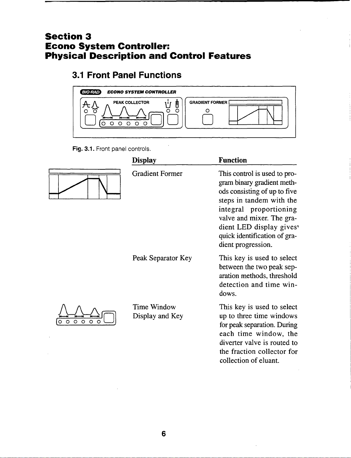
Fig. 3.1. Front panel controls.
~
~ro]O
Display
Gradient Former
Peak Separator Key
0
~
Function
This control is used to pro-
gram binary gradient meth-
ods consisting
steps in tandem with the
integral
valve and mixer. The gradient LED display gives,
quick identification
dient progression.
This key is used to select
between the two peak separation methods, threshold
detection
dows.
of
proportioning
and
up to five
of
gra-
time
win-
~
(o
o o o o
oO
Time Window
Display and Key
6
This key is used to select
up
to three time windows
for
peak separation. During
each
diverter valve is routed to
the fraction collector for
collection
time
window,
of
eluant.
the
Page 11
0 0
LIB
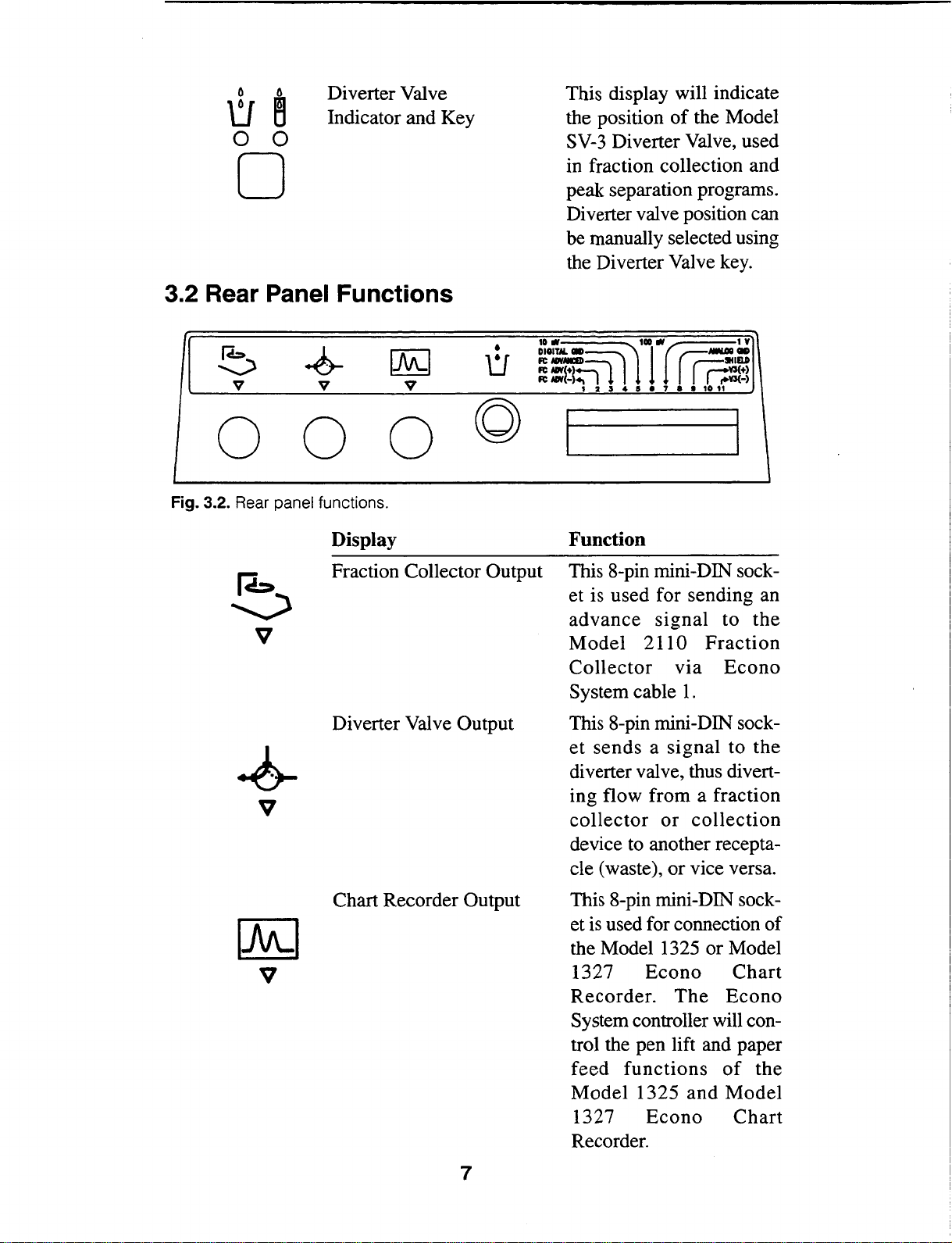
Diverter Valve
Indicator and Key
0 0
0
3.2 Rear Panel Functions
~
v
.&
v
~
v
•
LI
This display will indicate
the position
SV-3
Diverter Valve, used
in fraction collection and
peak separation programs.
Diverter valve position can
be manually selected using
the Diverter Valve key.
DIOITM.
CID
~~-~~--~1Y
a
:m:,
11
t234tle7aatou
of
the Model
-.Gil
1 lr
rr:~~
CID
0 0 0
Fig. 3.2. Rear panel functions.
Display Function
Fraction Collector Output This 8-pin mini-DIN sock-
Diverter Valve Output
©
et is used for sending an
advance
Model
Collector
System cable
This 8-pin mini-DIN socket
sends a signal
diverter valve, thus diverting flow from a fraction
collector
device to another receptacle (waste), or vice versa.
signal
2110
vta
or
to
the
Fraction
Econo
1.
to
the
collection
Chart Recorder Output
7
This 8-pin mini-DIN socket
is
used for connection of
the Model
1327
Recorder.
System controller will control the pen lift and paper
feed
Model
1327
Recorder.
1325 or Model
Econo
The
functions
1325
and
Econo
Chart
Econo
of
the
Model
Chart
Page 12
•
LJ
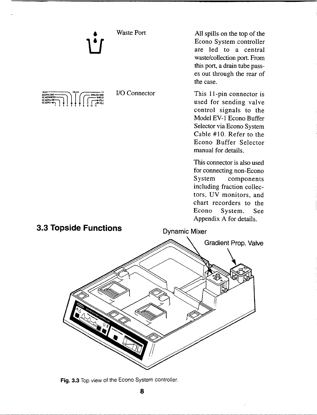
Waste Port
All spills on the top
Econo System controller
are
led
to a
waste/collection port. From
this port, a drain tube pass-
es out through the rear
the case.
of
the
central
of
10mY
DIGITALCHDSll
FCADVAHCED~
FCADV(•)~
FCADYH+, I I
1 2 3 4 5 6 7 8 9
100mV~1Y
1
~~ANALOGGND
rr.
SHIELD
r--*V3(•)
r+\'3{·)
10
11
110 Connector
3.3 Topside Functions
This 11-pin connector is
used
control
Model
Selector via Econo System
Cable
Econo
manual for details.
This connector is also used
for connecting non-Econo
System
including fraction collectors,
chart
Econo
Appendix A for details.
Dynamic Mixer
for
sending
signals
EV-1
UV
recorders
Econo Buffer
#1
0.
Refer
Buffer
components
monitors,
System.
valve
to the
to the
Selector
and
to
the
See
Fig. 3.3 Top view of the Econo System controller.
8
Gradient Prop. Valve
\
Page 13
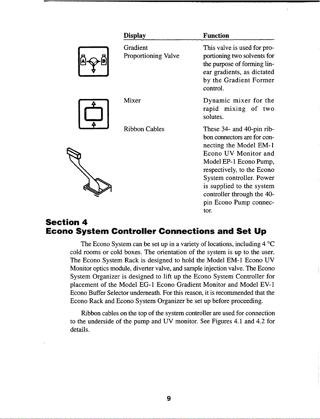
Display
Function
Gradient
Proportioning Valve
Mixer
Ribbon Cables
This valve is used for proportioning two solvents for
the purpose
ear
gradients, as dictated
by
the
control.
Dynamic
rapid
solutes.
These 34- and
bon connectors are for connecting the Model
Econo
Model EP-1 Econo Pump,
respectively, to the Econo
System controller.
is supplied to the system
controller through the
pin Econo Pump connector.
of
forming lin-
Gradient
mixer
mixing
40-pin rib-
UV
Monitor
Former
for
the
of
two
EM-I
and
Power
40-
Section
Econo
System
cold rooms or cold boxes. The orientation
The Econo System Rack is designed to hold the Model EM-1 Econo UV
Monitor optics module, diverter valve, and sample injection valve. The Econo
System Organizer is designed to lift up the Econo System Controller for
placement
Econo Buffer Selector underneath. For this reason, it
Econo Rack and Econo System Organizer be set up before proceeding.
to the underside
details.
4
Controller
The Econo System can be set up in a variety
of
the Model EG-1 Econo Gradient Monitor and Model EV-1
Ribbon cables on the top
of
the pump and UV monitor. See Figures 4.1 and 4.2 for
Connections
of
of
the system controller are used for connection
and
of
locations, including 4
the system is up to the user.
is
recommended that the
Set
Up
oc
9
Page 14
Econo Pump Econo UV Monitor
Diverter
Valve
G
Power~
Cable
"'<\
Cable
#1
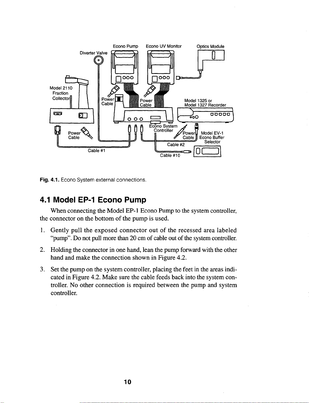
Fig. 4.1. Econo System external connections.
~=911==c=a=bl=e
Model
1325 or
Model 1327 Recorder
Systeif
Controller Power Model
Cable Econo Buffer
=#
::i::::::i=i:::P
2
~c=ab=le=#=1
o::c:::::::::J:D
{ 0 [
EV-1
Selector
J\
4.1
Model EP-1 Econo Pump
When connecting the Model EP-1 Econo Pump to the system controller,
of
the connector on the bottom
I. Gently pull the
exposed
"pump". Do not pull more than 20 em
the pump is used.
connector
out
of
of
cable out
the recessed area labeled
of
the system controller.
2. Holding the connector in one hand, lean the pump forward with the other
hand and make the connection shown in Figure 4.2.
3. Set the pump on the system controller, placing the feet in the areas indicated in Figure 4.2. Make sure the cable feeds back into the system controller. No other connection is required between the pump and system
controller.
10
Page 15
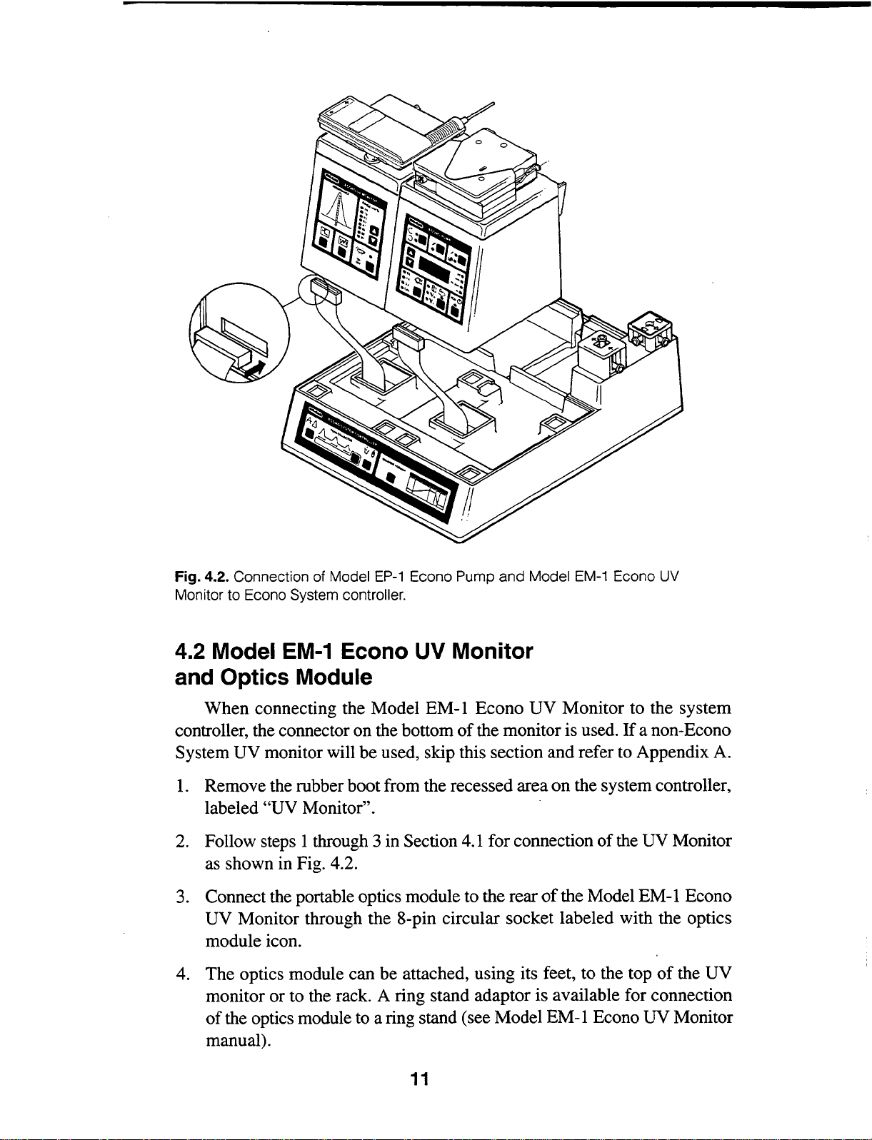
Fig. 4.2. Connection of Model
Monitor to Econo System controller.
EP-1
Econo Pump
and
Model
EM-1
Econo
UV
4.2 Model
EM-1
Econo UV Monitor
and Optics Module
When connecting the Model
controller, the connector on the bottom
System UV monitor will be used, skip this section and refer to Appendix A.
I. Remove the rubber boot from the recessed area on the system controller,
labeled
2.
Follow steps 1 through 3 in Section 4.I for connection
"UV Monitor".
as shown in Fig. 4.2.
3. Connect the portable optics module to the rear
UV Monitor through the 8-pin circular socket labeled with the optics
module icon.
4. The optics module can be attached, using its feet, to the top
monitor or to the rack. A ring stand adaptor is available for connection
of
the optics module to a ring stand (see Model EM-I Econo UV Monitor
manual).
EM-I
of
Econo UV Monitor to the system
the monitor is used.
of
the Model EM-I Econo
If
a non-Econo
of
the UV Monitor
of
the UV
11
Page 16
4.3 Model
EV-1
Econo Buffer Selector
and Model SV-5 Valve Pod
The Model
System Controller via Econo System Cable 10. Place the Econo Buffer
Selector control unit underneath the Econo
System Organizer is used) or beside the Econo System Controller. Use cable
#10 (supplied with the Econo Buffer Selector) to connect the Econo
socket on the rear panel
nector on the rear panel
The Model
of
the Solvent Reservoir in a variety
the length
Controller, and the buffer reservoirs. See the Econo Buffer Selector manual
for details.
EV-1
SV-5 Valve Pod can be mounted to the Econo Rack or the lip
of
tubing between the valve pod, the mixer on the Econo System
Econo Buffer Selector connects directly
System Controller (if the Econo
of
the Econo Buffer Selector to the 11-pin 1/0 con-
of
the Econo System Controller.
of
locations. For best results, minimize
to
the Econo
System
4.4 Model EG-1 Econo Gradient Monitor
The Model EG-1 Econo Gradient Monitor connects only to the chart
If
recorder.
Econo Gradient Monitor manual for details.
The Econo Gradient Monitor connects to the Model 1325 Econo (SinglePen) Recorder via Econo
Econo Gradient Monitor) to connect the standard DIN connector on the
Model 1325 Recorder to the 8-pin mini-DIN socket labelled with the chart
recorder icon on the rear panel
conductivity are to be monitored, the Model 1327 (dual-pen) Recorder (or
other dual-channel recording device) should be used. Use Econo
Cable 4 (supplied with the Econo Gradient Monitor, 8-pin mini-DIN to
banana plugs) to connect the Econo Gradient Monitor to the banana plug
signal inputs on the chart recorder. Plug the 8-pin mini-DIN end
to the chart recorder socket on the rear panel
Insert the black plug into the ground
voltage
a non-Econo Recorder is to be used, refer to the Model EG-1
System Cable
of
V input for channel 2
the Econo Gradient Monitor.If both UV and
of
2.
Use cable 2 (supplied with the
of
of
the Econo Gradient Monitor.
_l_ input and the red plug into the
the Model 1327 Econo Recorder.
System
cable 4
4.5 Model
Interfacing between the Model2110 Fraction Collector and system controller is achieved by connecting the 9-pin
Model2110 Fraction Collector to the 8-pin mini-DIN socket labeled with the
fraction collector icon on the rear panel of the system controller (refer to
Figure 3.2).
Controller) is used to make this connection. The fraction collector can also
be connected to the 8-pin mini-DIN socket labeled with the fraction collec-
211
Econo
0 Fraction Collector
1/0 connector on the back
System
Cable
1 (supplied with the Econo
of
the
System
12
Page 17
tor icon on the rear
System
fraction collector, refer to Appendix
of
the Model EP-1 Econo Pump. To connect a non Econo ·
A.
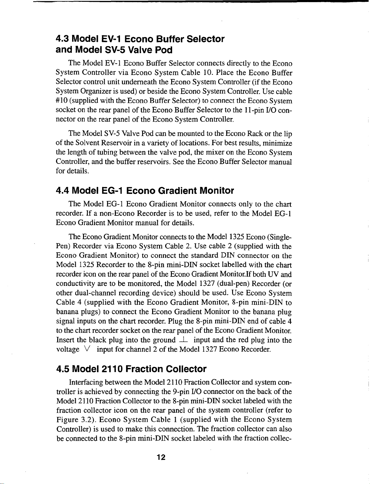
4.6 Model SV-3 Diverter Valve
The Model SV-3 Diverter Valve (Figure 4.3) can be attached to the rack
of
in a variety
are labeled to indicate their functions. The cable for the diverter valve is
attached to the back
et
labeled with the diverter valve icon (refer to Figure 3.2). The diverter
valve can also be connected to the 8-pin mini-DIN socket labeled with the
Diverter Valve icon on the rear
locations depending upon the application. The ports on the valve
of
the system controller using the 8-pin mini-DIN sock-
of
the Model EP-1 Econo Pump.
Fig. 4.3. Model
SV-3
Diverter Valve.
4. 7 Solvent Reservoir
The solvent reservoir sits in the depression in the system controller behind
the pump and
UV monitor.
Be
careful not to trap cables under the reservoir.
4.8 Model 1325 Econo (Single-Pen) Recorder
The Model 1325 Econo Recorder has been designed for use with the
Econo
analog data signal, pen drop, and paper feed command to the recorder. Refer
to the recorder instruction manual for operating details.
1325 Econo Recorder
plied with the system controller to connect the standard DIN connector on the
Model 1325 Econo Recorder to the 8-pin mini-DIN socket labeled with the
chart recorder icon on the rear panel
3.2).
tings labeled in green for automatic control.
System. Through one connection, the system controller will output the
To
connect the Model
to
the system controller, use Econo System Cable 2 sup-
of
the system controller (see Figure
Set all top panel controls
of
the Model1325 Econo Recorder to the set-
4.9 Model 1327 (Dual-Pen) Econo Recorder
The Model 1327 Econo Recorder has been designed for use with the
Econo
analog data signal, pen drop, and paper feed commands to the recorder.
System. Through one connection, the system controller will output the
13
To
Page 18
connect the Model 1327 Econo Recorder to the system controller, use Econo
System Cable 2 (mini-DIN to standard-DIN) to connect the standard-DIN connector on the Model 1327 Econo Recorder to the 8-pin mini-DIN socket
~
labelled with the
Figure 3.2).
icon on the rear panel
of
the system controller (See
4.10 Data Acquisition Systems
The system controller takes into account the use
data acquisition systems, such as the Model 3396A Integrator, or other instruments. The
Econo
Econo System Cable 7. Alternatively,
connected to the System Controller, the 11-pin connector on the rear panel
of
the system controller can be used. See Appendix A for signal specifications.
Section
5
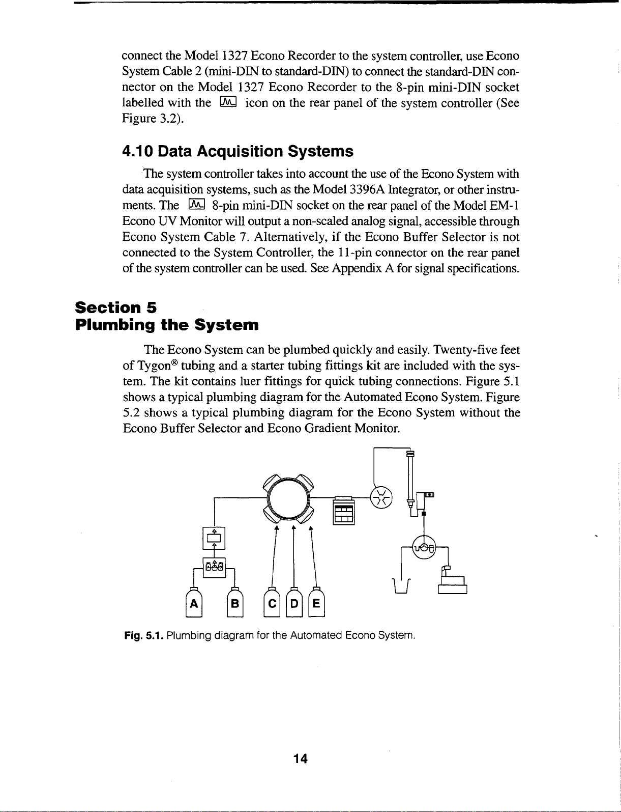
Plumbing
The Econo System can be plumbed quickly and easily. Twenty-five feet
of
Tygon® tubing and a starter tubing fittings kit are included with the system. The kit contains luer fittings for quick tubing connections. Figure 5.1
shows a typical plumbing diagram for the Automated Econo System. Figure
5.2 shows a typical plumbing diagram for the Econo System without the
Econo Buffer Selector and Econo Gradient Monitor.
of
the Econo System with
~
8-pin mini-DIN socket on the rear panel
UV Monitor will output a non-scaled analog signal, accessible through
if
the Econo Buffer Selector is not
the
System
of
the Model EM-I
u
Fig. 5.1. Plumbing diagram for the Automated Econo System.
14
Page 19

u
Fig. 5.2. Plumbing diagram for the Econo System (without Econo Buffer Selector
and Econo Gradient Monitor).
The plumbing arrangement described in this section is by no means the
only way to connect the system. The additional tubing and fittings are supplied to allow the system to be customized for specific applications.
5.1
Tubing and Fittings
The Econo System can be conveniently plumbed with most tubing having inner diameters less than or equal to 3.2 mm
supplied in the plumbing kit is 1.6 mm ID. This should suffice for most
applications. When using 3.2 mm tubing in the pump for increased pump
output, the proportioning valve and mixer should also be plumbed with 3.2
flow.
mm tubing to maintain adequate
manual for tubing compatibilities with the pump.) Figure 5.3 summarizes
the more commonly used fittings.
(Refer to the Model EP-1 Econo Pump
(Ys").
The Tygon tubing
Male luer for system tubing connections
Female luer for pump tubing
.,.
Female 't' connector
1 Male-to-male connector
Fig. 5.3. Fittings for system tubing connections.
15
Page 20

Note: Tubing lock-rings are used only for plumbing the Model EP-1
Econo Pump and are not needed for system tubing connections.
5.2 Gradient Proportioning Valve and Mixer
The length
valve is not critical; however, it is important
be designated buffer A and buffer B.
1.
Insert the barbed end
Connect the male luer fitting to the female luer fitting on the propor-
tioning valve. Make sure that the line from buffer A is connected to the
A port on the proportioning valve. Repeat this process for buffer line B.
Do not overtighten the luer fittings.
2. The connection between the proportioning valve and mixer should be
made with a piece
accuracy
luer fittings
the outlet
Figure 5.1).
5.3 Model
Installation
EP-1 Econo Pump manual. Pre-cut norprene tubing and fittings are supplied
with the pump.
tubing, refer to the following procedure. Note that tubing length varies with
tubing composition. This is to accommodate tubing prestretch, which affects
flow rate calibration and flow reproducibility.
of
tubing between the buffer bottles and the proportioning
to
clearly label which bottles will
of
a male luer fitting into one end
of
tubing less than
of
the gradients formed by the proportioning valve. Affix male
to
both ends
of
the proportioning valve with the inlet
EP-1
of
To
Econo Pump
the tubing in the pump head is described in the Model
make these tubing sections yourself with Tygon, or other
of
the tubing as described above, and connect
10
em long. This
of
the tubing.
is
to maintain the
of
the mixer (see
Warning:
sure the wall thickness is not greater then
greater wall thickness can damage the pump and void your warranty.
1.
Cut the tubing to a length described below. Make sharp, perpendicular cuts.
Tubing
Tygon, Norprene
Silicone
2.
Slip a color-coded lock-ring specific for that size
of
the tubing (see below). Install the female
barbed end
place by sliding the lock-ring over the barbed fitting (see Figure 5.4).
Repeat on the other end
If
using tubing other than the type supplied by Bio-Rad, make
0.8 mm. Using tubing with a
Length
179
mm
+1-
1.3 (7.04"
171
mm
+1-
1.3 (6.75"
of
the fitting into the tubing, and clamp the luer fitting into
of
the tubing.
16
+1-
0.05)
+1-
0.05)
of
tubing onto one end
1uer
fittings by inserting the
Page 21

Lock-Ring
Color
Size
Red
Orange
Yellow
If
a Model
EV-1
Econo Buffer Selector is not being used, the connection
between the pump and the mixer should be made with a section
then
15
em long to maintain accuracy
0.8 mm
1.6
3.2 mm
of
gradients. Affix male luer fittings
mm
(~2")
(YI6")
(Ys")
of
tubing less
to both ends as described above, and connect to the female luer fittings on both
the pump outlet and the mixer.
If
a Model
mixer to the pump. Continue with
EV-1
Econo Buffer Selector is to be used, do not connect the
Section 5.4 for plumbing the Model SV-5
Valve Pod.
Fig. 5.4. Attachment of tubing fittings.
5.4 Valve Pod
The Model SV-5 Valve Pod should be positioned as close as possible to
the mixer on the Econo
of
tubing should be
should already be plumbed through the proportioning valve and mixer on
the Econo
the Econo
System Controller. Connect tubing from the outlet
System controller to the
Pod. Connect tubing from each buffer/sample reservoir (C, D, E) to the corresponding valve port on the Model
the outlet port
of
the valve pod to the Model EP-1 Econo Pump.
System controller and the Econo Pump. The length
of
minimal length and inner diameter. Buffers A and B
of
the mixer on
AlB
inlet port on the Model SV-5 Valve
SV-5 Valve Pod. Connect tubing
17
fro~
Page 22

5.5 Manual Sample Injection Valve
and Chromatography Column
Samples can be introduced into the flow path
of
variety
below.
tem, post-pump; the other allows pre-pump variable injection volumes. The
MV-6 injector valve
three-way valve can be inserted in-line between the pump and the column inlet
or
between the pump and mixer to provide a simple injection port. For details
on automated sample injection, see Section 7.8.
ways. Two methods for manual sample injection are described
One uses preset injection volumes with a classical injection loop sys-
can
be used in both configurations. Alternatively, a
of
the Econo System in a
18
Page 23

Post-Pump Injection with a Sample Loop
1.
The Model MV-6 Injector Valve can be installed in a variety
tions on the rack.
Use the screw fitting on the injector valve housing to
of
loca-
secure the valve.
of
2. Cut a section
tubing long enough to connect the pump and the injec-
tor port. Affix male luer fittings as described above.
of
3. An injection loop
of
tubing
of
a length which corresponds to a desired volume. Table 5.1
a desired volume can be formed by using a section
provides the tubing lengths that correspond to several common loop
volumes.
of
4. Attach a male luer-fitting to each end
the sample loop tube.
5. Connect the inlet line from the pump, sample loop, and outlet line to the
column
as
shown in Figure 5.4. Arrow indicates rotation direction of valve.
Waste
Sample Loop
~
Pump
Fig. 5.5. Tubing connection for post-pump injector valve placement.
Pre-Pump Injection
1.
Install the injector valve on the rack in a location close to the mixer.
2. Disconnect the tubing between the pump and mixer.
3. Connect the mixer to the injector valve, and the injection valve to the
pump, as shown in Figure 5.5. Arrow indicates rotation direction
valve.
Column
of
19
Page 24

Mixer
Sample
Econo
Pump
3-way
Stopcock
Fig. 5.6. Tubing connection for
Table
Tubing
0.8mm
0.8mm
1.6mm
1.6
1.6mm
3.2mm
3.2mm
3.2mm
3.2mm
mm
5.1
Sample Injection Loop Volumes by Tubing ID
10
pre-pump
Loop Tubing
Volume
100
200
200
500
1
500
1
2ml
5ml
injector valve placement.
Jll
Jll
Jll
Jll
ml
Jll
ml
Length
14
em
34em
8.5em
23.5 em
48.5 em
5.9em
12.1
em
24.6 em
62.1
em
Note: Luer fittings and valve internal passages add approximately 60
above volumes.
J..l].
to
5.6 UV Optics Module
and Gradient Monitor Flow Cell
The Model EM-I Econo
as close to the column outlet as possible, to minimize mixing
sample prior to detection. The tubing end used to connect the outlet
matography column should have a female luer fitting attached. Arrows on the
of
top
the optics module are used to indicate flow direction. The tubing ends
to be connected to the inlet
affixed with a male luer fitting. It is important to minimize the length and inner
of
diameter
this section
of
tubing.
UV
Monitor optics module should
and
outlet lines
of
the
UV
20
be
coupled
of
the separated
of
the chro-
monitor should
be
Page 25

Connect the Model EG-1 Econo Gradient Monitor flow cell directly to
or
the inlet
detection.
Warning: Do not overtighten the luer fittings.
5.
7 Model SV-3 Diverter Valve
The Model SV-3 Diverter Valve should be coupled as close as possible
to the UV monitor outlet. The length
length and inner diameter. Connect two sections
fitting on one end and connect to both the collect and waste ports
diverter valve. Direct the tubing from the waste port to an appropriate waste
container. Connect the tubing from the collector port to a fraction collector
or suitable collection device as described in Section 5.8.
outlet port
of
the UV optics module for optimal conductivity
of
tubing used should be
of
tubing with a male luer
of
minimal
of
the
5.8 Fraction Collector
To
connect the diverter valve to the Model2110 Fraction Collector, affix
a male luer fitting to one end
to the female luer fitting to the collection port
Place the other end
drop forming arm. See the Model
ual for details on this connection. Minimizing the length
this connection will improve the accuracy with which peaks are collected.
of
the tubing into the rubber ferrule
of
a length
2110 Fraction Collector instruction man-
of
tubing, and attach this connector
of
the flow diverter valve.
of
the fraction collector
of
tubing used for
Section
Getting
It
is
ule. Refer to Section 2.2
6.1
1.
2.
3.
4. Model EG-1 Econo Gradient Monitor (requires power adaptor)
5.
6. Model 1325
6
Started
After the Econo System is connected and plumbed, it can be powered up.
important that the input voltage match the voltage on the power entry mod-
if
it does not match.
Connecting System to Power
The following line cords need to be connected to power up the system.
Model EP-1 Econo Pump
Model EM-1 Econo UV Monitor
Model
Model 2110 Fraction Collector
power adaptor)
EV-1
Econo Buffer Selector (requires power adaptor)
or
Model 1327 Econo Recorder (optional, both require
21
Page 26

The Model EP-1 Econo Pump will supply the power to the system controller through the ribbon cable connected to the pump base. The Model EM-1
Econo
the gradient monitor, buffer selector, chart recorder and fraction collector. The
UV monitor is powered up with the lamp on. Ensure that the optics module
is plugged into the appropriate socket on the rear panel
The
15
warm up.
UV Monitor is plugged directly into a grounded power source, as are
of
the UV monitor.
UV lamp LED will flash during the first minute
minutes for the UV lamp, and 10 minutes for the gradient monitor to
or
two. Allow at least
6.2 System Check
Before proceeding, it is advisable to check the system for leaks or other
problems.
reservoir containing water. Disconnect any chromatography column during
the test.
To
carry out the test, place buffer lines for buffer A and B into a
0 0
LJ
• 0
0
~
1.
2.
3.
4.
Press the Run/Stop key on the pump front panel.
The run and % light will come on, and the pump
display will read
Press the Waste/Collect key on the system controller
front panel until the waste light is lit. When the valve
cycles between waste and collect, a click should be
If
heard.
controller.
Using the scroll keys on the pump, increase the pump
output to 25%. The pump head should begin to tum.
Over the next 10 minutes, watch for any leaks
bubbles.
tered, press Run/Stop to stop the pump, and repair the
leak and remove air bubbles. Restart the pump.
not, check the connection with the system
If
leaks
0.
or
excessive bubbles are encoun-
or
air
22
Page 27

5.
Press the Purge key on the pump front panel and let
pump operate at
buffer A for several minutes. Again, check for any
leaks in the system. When purging, the diverter valve
be
should
in the waste position.
100% maximum output
(25
rpm)
of
6.
7.
To prime with
Former key (see Figure 3.1) while in the Purge mode.
The Gradient Former indicator light will flash and the
pump display will show a flashing
100% buffer B output.
Note:
E (if the Econo Buffer Selector is being used), the
system must be configured in the Enhanced mode
(See Section 7 .1). Buffers A through E can then be
selected by depressing the Gradient Former key.
Release the key when the desired buffer
on the Econo Buffer Selector display. The valves
will not change until the key is released.
Press the Run/Stop key to stop the pump,
Purge key once more to put the pump into Run mode.
To
prime the buffer lines for buffers C, D, and
100% buffer B, press the Gradient
"b" to indicate
is
displayed
or
the
Section
7
Programming
The Econo System components function in the system configuration
much the same way they do in the stand-alone configuration. For more specific details on the operation
uals supplied with them. This section summarizes the function
in various separation strategies, and various levels
7.1
Getting Started: Verification of Econo System
Software Version
The Model EP-1 Econo Pump must have software version 2.01 or high-
er
to control the Model EV-1 Econo Buffer Selector.
include a Model
does include a Model
sion
of
your system before proceeding:
the
EV-1
System
of
the individual components, refer to the man-
of
If
Econo Buffer Selector, see Section 7
EV-1
Econo Buffer Selector, check the software ver-
of
the system
complexity.
your system does not
.2.
If
your system
23
Page 28

Simultaneously press and hold the Direction Key
and the
Model EP-1 Econo Pump. The four digit LED display on the front panel
play:
If
your Econo Pump displays a number lower than 2.01. it must be
upgraded. Call your local representative for an EP-1 ROM Replacement Kit.
Disconnect the Econo Pump from all connections and replace the ROM following the directions in the
procedure takes about
replacement, please contact your local Bio-Rad representative.
If
your pump currently features software version 2.01 or higher,
ROM upgrade has already been completed, ensure that all connections
between the Econo Pump, Econo
have been completed and the system power is on.
15
"down" Arrow key on the front panel
of
the Econo Pump should dis-
"v2.01"
ROM Replacement Kit. The ROM replacement
minutes.
If
you do not wish to perform the ROM
System Controller and Econo Buffer Selector
or
of
if
the
the
7.2 Econo System Software Mode Selection
Software version 2.01 and higher features two user-selectable programming modes, Standard and Enhanced. The "Enhanced" software mode is
required to use the Model
choice whenever more than two buffers will be controlled, methods longer
than 5 steps or automated sample injection is desired. The "Standard" soft-
is
ware mode
5 steps, including simple binary gradient methods.
the mode
EV-1
of
choice for methods requiring 1-2 buffers, and
Econo Buffer Selector and is the mode
of
1-
To
choose the software mode
1.
_j'o0
@e
2.
tJ~
0 0
0
3.
of
operation:
Stop the pump.
Ensure that the "Gradient Former" light
the "gradient former " button
light off.
While depressing the Diverter Valve Key, press and
hold the Gradient Former Key on the front panel
the Econo System Controller for approximately 3
seconds. The indicator lights on the front panel
Econo
play
Standard Mode or "Enh" for Enhanced Mode.
Pump will flash and the four-digit LED dis-
on
the
pump
will
if
necessary to tum the
display
either
is
off. Press
"Std"
of
of
the
for
24
Page 29

4. To choose a mode, press the Arrow Keys to choose
between
"Std" and "Enh".
5.
~
To accept the selected mode, ensure that it is dis-
played on the four-digit LED display, and press the
Run/Stop Key on the front panel
~
The system will remain in the mode selected until a
different mode is selected (even after power-down.)
The Standard and Enhanced modes have separate
memories. Methods programmed in one mode do
not affect the other.
7.3 lsocratic (Single-buffer) Methods
To
run the system in a simple isocratic mode (use
only the buffer A inlet, use the following procedure.
1.
Ensure that both the Model EP-1 Econo Pump and
Model EM-I Econo UV Monitor are plugged into a
grounded power source. The pump will power up in
UV
the Stop mode, and the
Allow at least
15
minutes warm-up time for the UV
monitor with the lamp
lamp.
of
the Econo Pump.
of
only one buffer) using
on.
o 0.8
0 1.6
03.2
0 CAL
IWCIE (,WPS)
Q
z..o
c
1.0
c o .
.s
"'0·:1~
Cl
0.1
~
"'
.os
"'
...
5\
Q
.01
l.Y..J
01
0
2.
Configure the system
in
the "Std" software mode.
Refer to Section 7.2 for instructions.
3.
Set the desired
UV sensitivity using the arrow keys
on the UV monitor front panel. See the UV monitor
manual for details.
4. When using the system in an isocratic fashion, make
sure that solvent line A
is
being used, and is properly
connected to the proportioning valve. Cap the unused
"B"
port on the proportioning valve.
5.
Calibrate the pump by either choosing one
pre-selected tubing sizes,
or
user-calibrating any
of
three
tubing. See the pump manual for detailed calibration procedures.
6.
With the tubing in place, set the desired pump speed
in ml/min using the arrow keys.
25
Page 30

To
initiate flow, press the Run/Stop key.
To
stop
flow, press once more. Flow rate will be displayed
mllmin. Change the flow to the desired speed
in
while the pump is running by pressing the arrow
keys.
tiB
• 0
0
8
Eluant can be directed
using the two-way diverter valve key located on the
system controller,
plumbed.
Simply press the key
to
suitable collection devices
if
the diverter valve has been
to
light the indicator
light below the figure corresponding to either waste
of
or collect. The default position
the valve is in the
waste position.
Tip: The system can be programmed for automatic shut-off
cratic run. This can be done by programming a total run volume
of
(V
pump will shut off once the total run volume has been delivered. For
detail, see
Tip in the following section.
Time Based Collection
with the Model 211 0 Fraction Collector
To
enable the Model 2110 Fraction Collector:
1.
Connect the fraction collector to the system con-
or
troller
System Cable
Model EP-1 Econo Pump using Econo
1.
the iso-
).
The
1
2.
Press the Fraction Collector key on the Model EP-1
Econo Pump front panel to enter the fraction collector edit mode. In the edit mode, only the flashing
keys are active. Note that the Fraction
indicator lights are flashing, prompting entry
tion size. Enter the fraction size
using the Arrow keys.
entered, press the Fraction Collector key once more
to confirm the fraction size.
3. Enter a void volume
the Arrow keys. See the Model EP-1 Econo Pump
manual for details on the Void Volume (V
tion. Press the Fraction Collector key to confirm this
value and enter the Total Run Volume
If
a void volume is not desired, set V o to zero.
26
(V
After
)
in 1
0
in
Size and
0.1
ml increments
of
ml
frac-
the fraction size is
ml
increments using
)
func-
0
(V
edit mode.
)
1
Page 31

4.
5.
Enter the Total Run Volume (Vt) in 1 ml increments
using the Arrow keys.
the fraction collection scheme is disabled.
data entry, start at Step 2 above. All values previously entered remain in the memory until other values
are entered to replace them.
After entering a
Collection key to confirm the value. The flashing LED
multi-display shows the estimated number
tions to be collected.
If
zero
is
entered and confirmed,
To
resume
Vt
value, press the flashing Fraction
of
frac-
6.
7. For options while running a method, see Section 7.9.
8.
Lf9
le.BFHI
Press the flashing Fraction Collection key once more
to enable the fraction collector.
played in ml/min.
press the
it was not already running. (The fraction collector can
be programmed with the pump running
After the fraction collection program is initiated, the
LED display shows the progression
collection scheme in minutes, to the nearest tenth
minute.
Note: Insure that sample has been injected into the
column before starting a program.
To
abort the fraction collection scheme at any time
during the program, press the Run/Stop key twice.
The pump will stop, and the LED display will read
OFF.
Program Run key after starting the pump, if
To
actuate the fraction collector,
Pump output is dis-
or
stopped.)
of
the fraction
of
a
9.
TIP: The fraction collection control feature
can be used to tum
Simply enter zero for fraction size. After
if
the pump,
The pump will stop automatically when the total run volume has been deliv-
ered.
not already running, then press the flashing Program Run
To
hold a collection program that has begun, press the
lit Program Run key once.
program, press once again.
while the program is on hold will abort the fraction
collection scheme.
of
off
the pump even
if
a fraction collector is not connected.
confirming the V t value entered, start
To
resume the collection
Pressing the Run/Stop key
the Model EP-1 Econo Pump
key.
27
Page 32

7.4 Binary Gradient Formation
The Econo System gradient former functions with the Model EP-1 Econo
Pump and the integral proportioning valve and mixer to form a binary gradient consisting
gradient on the front panel
is by no means the only way to
of
up to five time segments. Note: the graphic display
of
the system controller is provided as a guide,
format
a five segment gradient.
of
and
a
o 0.8
0 1.6
03.2
0 CAL
01
0
1.
The pump must be calibrated in order to form gra-
of
dients. See Section 5.2
the Model EP-1 Econo
Pump manual for details.
2.
Configure the system in the "Std" software mode,
if
not already done. Refer to Section 7.2 for instruc-
tions.
3. The gradient profile can be constructed in the following way:
Inflection
Point Elapsed
I 0
2
3
4
5
6
Time
T2
T3
T4
T5
T6
%B
Bl
B2
B3
B4
B5
B6
4.
5.
Press the gradient key once. The
min
light on the
pump and the pump display will flash "0", to indicate time=O. Press the gradient key once more. The
% light on the pump will flash, along with the light
above the first gradient point on the gradient dis-
0,
or
play. The pump display reads
ly entered value
for initial % B
for%
(B
of
buffer
1)
using the Arrow keys. Confirm
the most recent-
B.
Enter a new value
entry by pressing the Gradient Former key.
The gradient point indicator will then advance to the
next gradient inflection point. Note the flashing
"min" indicator light on the pump. Enter the time
desired for the first gradient step (T2), or leave the
previously entered value unchanged. Confirm this
value by pressing the Gradient Former key.
28
Page 33

6.
The flashing
% LED indicator light prompts entry
of
a % B value for this inflection point (B2). Enter the
new value, and press the Gradient Former key to
confirm this entry and advance to the next gradient
inflection point.
7. Follow steps 4-5 for the remaining gradient points.
8.
9.
10.
If
using fewer than the six inflection points allowed,
scroll through the time and
% points for the remain-
ing gradient inflection points by pressing the Gradient
Former key, without changing the values showing.
Note: The stop indicator light on the pump will flash
at every step during programming to indicate that
this key may be pressed at any time to exit the edit
mode. Upon exit, any changes made to the method
are automatically saved.
After the last % B value has been selected (or left
unchanged) and confirmed, the gradient former will
be enabled, as indicated by the lit Gradient Former
key.
If
a fraction collection program has been entered
previously (note light under the fraction collector
of
icon on pump front panel), the number
fractions
to be collected will be re-estimated and displayed
at this time.
Press the flashing Gradient Former key
a final time. The LED will be lit steadily, indicating
a gradient is programmed and enabled.
At this point, the gradient former
formation.
If
the gradient is not desired, press the
is
set
up
for gradient
Gradient Former key one more time to tum off the
gradient former indicator light.
29
Page 34

To
begin the gradient scheme, press the Run/Stop
If
key to get the pump running.
condition programmed is not
you will hear the proportioning valve clicking as
the system operates at initial gradient conditions.
start the program, press the flashing Program Run
key
on
the pump. The gradient program will begin,
with the LED display showing minutes progressed.
To
observe the other parameters
scroll through with the Arrow keys as described
Section 7.9.
Note: Insure that sample has been injected into the
column before starting a program.
the initial gradient
100% A or 100% B,
To
of
the program,
~n
13. For options while running a method, see
Binary Gradient Time-Based
with
the
Model
The system should be configured in the "Std" mode,
See Section 7.2 for instructions.
0
0.8
orr
0
1.6
03.2
0
0
CAL
oBJ
~
0 v
o
0
v~
0
211
0 Fraction Collector
1.
2.
3.
Calibrate the Model EP-1 Econo Pump as described
in the pump manual.
Enter a fraction collection program as described in
Section 7.3. See Appendix A for connection
fraction collectors.
Program a gradient as described previously.
Collection
Section 7.9.
if
not already done.
of
other
4.
~r7onlo
lQJ~
5.
Start the pump to begin the gradient at initial conditions(%
collection by pressing the flashing
To
discontinue collection only, press the Run/Stop
key twice, and turn off the fraction collector by pressing the Fraction Collector
once more to start the pump, and the Program Run
key to start the gradient at initial conditions.
30
Bl).
Start the binary gradient time-based
Program Run
key.
Then press Run/Stop
key.
Page 35

6.
Note: After the gradient former program has been entered, the total vol-
(Vt)
ume
and estimated number
ed based on the total gradient time and flow rate.
Fraction Collection program to view the adjusted
For options while running a method, see Section 7.9.
of
fractions to be collected will be adjust-
Scroll through the
Vt
and fraction num-
ber values.
7.5 Peak Detection and Collection
The peak detection and separation functions
of
the Econo System allow
the user to discriminate among various chromatographic peaks using either
or
an absorbance threshold programmed into the system,
by setting time
windows, where collection occurs within selected time windows. Both meth-
of
ods
peak collection operate using the Model SV-3 diverter valve, which
functions to divert the eluant stream from a waste line to a collection line. This
collection line can be directed into a fraction collector for more precise peak
breakdown,
gram, gradient former,
tion function.
"Std"
Fig. 7.1. Peak detection and collection features.
or
or
into any suitable collection device. A fraction collection pro-
or
auto shutoff must be used with the peak collec-
Peak detection and collection features may be used in either
"Enh" software modes.
PEAK COLLECTOR
Peak Collection by Threshold
Peak collection on the basis
of
sion
peaks to a fraction collector, while directing non-peak eluant to a
of
threshold detection allows for the diver-
waste container or other collection vessel. This
a peak threshold value in percent full scale
1.
To operate the threshold detection function
UV absorbance.
Econo System, a fraction collection, Vt timer,
gradient formation program must be enabled. See
Section
7.3 and 7.4 for details.
31
is
accomplished by selecting
of
the
or
Page 36

~
~
A:.
)C:
:;~:
..
_;
A
• '0
0
:'0)-
..
,~JU
NO
0
-:~
2.
Press the Peak Collector key until the indicator light
below the threshold icon is flashing. The Pump LED
will read %, prompting entry
for percentage
Arrow keys to scroll up
threshold value. For reference purposes, each green
light on the absorbance display
Econo UV Monitor equals 10%
lights
lit=
50%
of
full-scale absorbance. Use the
or
of
full scale).
down
of
a threshold value
to
select the desired
of
the Model EM-I
of
full scale (five
:A:.
• '0
0
~~
@ ,..
BZJI::·8.3BI..:~
0
08
• 0
0
t!B
• 0
0
o
BJ
~
0
Vo
•
0
v,
0
3. After entry
A
Collection key once more to enable threshold detection. The light below the threshold icon will be lit.
4. To
Run/Stop key, followed by the flashing
Run key.
key twice within 1 second.
5.
•O
>0
6.
When
is in the Waste position, with the light under the
is reached, the diverter valve will switch to Collect,
and a mark
recorder tracing.
If
start
waste icon lit. The pump LED display reads minutes progressed. When the selected threshold value
a void volume has been programmed, the valve
will remain in the waste position for the duration
the
void.
absorbance is above the selected threshold value,
the valve will revert to collect, then back to waste
after the absorbance drops back below the set threshold value. With each valve change, a mark will be
superimposed on the recorder tracing.
of
this threshold value, press the Peak
the
peak
To
Stop the program, press the Run/Stop
Peak Collection is enabled, the diverter valve
will
At
be
the
detection
end
program,
superimposed
of
this time period,
press
Program
on the
the
chart
of
if
the
0
LI
0 0
0
B
7.
The Diverter Valve key allows the user to toggle
back and forth between waste and collect. The Peak
Collection function will override the manual place-
ment
valve has been manually placed into the collect position prior to a peak, when that peak
valve will stay in the collect position, then switch
of
the diverter valve. That is,
if
the diverter
is
detected, the
32
Page 37

to waste on the tail end
value.
of
the peak when the absorbance drops below the set
AA
• '0
8
0
0 0 9
l1 B .
0 0
0
11.
~~0
LQJ~
To change the threshold value during a run, press
·
the
Peak Collection key to enter the edit mode for
by
threshold detection, indicated
under the threshold icon.
indicator lights will now
of
a threshold value in % full-scale absorbance. To
confirm this value, press the
once more. The
changing the threshold setting.
If
the
new
absorbance value currently seen
tor, the diverter valve will switch from collect to
waste, and vice versa
current value.
To terminate the method, press the Run/Stop key
twice within 1 second. For other options while running a method, see Section 7. 9.
pump
threshold
The
show%,
will continue
value
if
the new value is less than the
a flashing light
pump
Peak
is
LED
prompting entry
Collection key
to
greater
by
the
run
than
UV
display
when
the
moni-
Peak
material known to elute at a specific time. The user can select the starting and
ending times for three peaks, as indicated
beneath the three representative peaks (see Figure 7.1). To operate the time
windows method
dient formation feature must be enabled.
Collection by
Peak collection on the basis
AA
0
'i'
0
~0
(•
o o o o
oD
Time
of
peak collection, the fraction collection, V1 timer,
1.
2.
3.
To enter the edit mode for time windows collection,
press the
until the light below the time window icon flashes.
Enter a time value for the starting point for the first
peak in
on the pump.
To
advance to that time window end point, press the
Time Windows key.
Windows
of
time windows will simplify collection
by
the six indicator lights located
Peak Collection key, and continue pressing
0.1 min increments using the Arrow keys
confirm
the
time
window
starting
or
point
of
gra-
and
33
Page 38

/l-6-6
(•
• o o o
oO
4.
Enter the time window endpoint value in
increments using the Arrow keys. Advance to the
next time window starting point by pressing the
Time Windows key.
0.1
min
AA
0
..
0
t!B
• 0
0
~
0
0
5.
6.
7.
if
or
Peak
the
V o is
Repeat steps 2-4 for the remaining two windows,
confirm entry
time window collection feature by pressing the
Collector key. The light beneath the Time Windows
icon will be lit solid, indicating
windows feature.
To
start
Run/Stop key followed by the flashing Program Run
key.
The diverter valve will reside in the waste position
until a time window is reached. At that point, the
valve will switch over to the collect position. The
valve can be manually switched using the Diverter
Valve key. The position determined by the programmed time window feature will override any
manual positioning
superimposed over a time window, the diverter valve
will be in the waste position.
Fraction Collector key.
the
of
that time window and enable the
Time
activation
Windows
of
the valve. However,
program,
To
cancel V
of
press
o'
the time
press the
AA
0 'i'
8.
0
~~o
9.
Changes to the window's start and end points can
be made by stopping the program, scrolling through
the time windows with the Time Windows key, and
entering and confirming the new values as described
Steps 2-4. Pressing the Peak Selector key without
in
changing any
viously entered values and invoke Time Windows.
To
terminate the Time Windows program, press the
Run/Stop
options while running a method, see Section 7.9.
of
the time points will confirm all pre-
key
twice within 1 second.
For
other
34
Page 39

The Time Windows detection function can be run
in tandem with the gradient former to optimize sample collection. Simply program the gradient former
as described above prior to invoking the time win-
dows collection function.
7.6 Programming Multi-Step Methods
(Using the Econo Buffer
Note:
mode
The
Econo System must be configured
for
automated valve control using the Econo Buffer Selector.
Selector)
in
the Enhanced software
you are not familiar with programming the Standard Econo System,
7.1-
7.5
of
please review Sections
10
13
23
33
43
55
55
55
this manual before proceeding.
B
c
D
E
A
A
A
End
If
where:
Table 7.5. A Typical Method Table for a Multi-Step Method. The method outlined
consists of 4 buffers, 1 sample, and 6 steps (7 inflection points).
Programming methods in the Enhanced software mode involves a method
table with a maximum
Table 5.4 and Table 5.4.b.). Each inflection point is defined by an elapsed
(cumulative) time and a buffer/valve position. Any buffer/valve position
may be selected at each inflection point.
A multi-step method is a method which consists
from one buffer to another. The Model
trol up to 5 different buffers (one
can consist
of
up to 8 steps (created by 9 inflection points).
A = Loading Buffer
B
=Sample
C = Elution Buffer
D = Elution Buffer #2
E = Regeneration Buffer
of
9 inflection points (equivalent to 8 steps) (See
of
35
#1
of
a sequence
EV-1
Econo Buffer Selector can con-
which could be a sample) and a method
of
steps
Page 40

o
0.8
0 1.6
03.2
0
CAL
or
0
1.
The Econo Pump must be calibrated: Calibrate the
Model
EP-1 Econo Pump manual.
EP-1 Econo Pump as described in the Model
2.
3.
Press the Run/Stop key to stop the pump.
Press the Gradient Former key once. The pump dis-
play will flash
digit display on the Buffer Selector will flash
cating the first inflection point in the method.
0,
indicating
time=
0. The single
1,
indi-
Note: The Stop indicator light on the pump will flash at every step dur-
to
ing programming
exit the edit mode. Upon exit, any changes made to the method are automatically saved.
4.
indicate that this key may be pressed at any time to
Press the Gradient Former key again. The single-
digit display on the Buffer Selector will still be flash-
1 for inflection
ing
pump
appear on the pump display. (L is used for binary
gradient steps and is explained in Section 7.7.)
will flash, and a letter (A,b,C,d,E,L) will
point
#1. The % light on the
8.
Use the
Confirm the entry by pressing the Gradient Former
key.
The min indicator light on the pump will flash and
the single-digit display on the Buffer Selector will
flash 2, indicating inflection point #2. Using the
Arrow keys, enter the elapsed time desired for the
second inflection point.
Gradient Former key.
The
Arrow
% light on the
keys
to
select a valve
Confirm entry by pressing the
pump
will flash, and a letter
position.
(A,b,C,d,E,L) will appear on the pump display. Use
the Arrow keys to select a new valve position. Press
the Gradient Former key to confirm the entry and
advance to the next inflection point.
Repeat steps 6-7 for the remaining inflection points.
36
Page 41

9.
If
using
points, scroll through the time and % points
remaining method inflection points
Gradient Former key, without changing the values
showing,
Run/Stop key.
*If
viously entered method are not automatically erased.
Ensure
gramming steps will not interfere with the current
method.
After the last elapsed time point has
and confirmed (inflection point
the
"End". Press the Gradient Former key once more
to
enable the method. The Gradient
tor
If
a
entered (the Fraction Collector indicator light
pump
of
will
"F
confirm the gradient program.
indicator light should
fewer
the edit mode is exited, data points from any pre-
that
Buffer
light should be lit.
fraction
front panel will
fractions to
be
re-estimated and the pump display will flash
###".Press
than
the
maximum
or,
exit
the
edit
the
data
points
Selector), the
collection
be
collected
the flashing Gradient
program
be
lit), the estimated
be
lit.
of 9 inflection
by
pressing the
mode
pump
by
pressing
in
the
remaining
been
#9
as displayed
display will flash
Former
was
previously
in
the method entered
Former
The
Gradient Former
for
the
the
pro-
entered
by
indica-
on
the
number
key to
17-nl~
12.
~lQJ
13.
14.
To begin the method, press the Run/Stop key to start
the
pump
start
To
Program Run key on the pump.
The pump display will show a flashing
number
repeat.
to 999. The default for n is
If
a manual sample injection is
method, ensure that sample has been injected into
the column before starting the program.
Press the Program Run key to confirm the entry
"n".
appear on the chart paper.
running at the initial gradient condition.
the
method
of
times the method should automatically
Use the Arrow keys to enter a value from 1
The
method will begin and an event
program,
1.
press
the
"n". "n" is the
necessary
flashing
for
mark
the
of
will
37
Page 42

7.7 Programming Step Methods Which Include
a Binary Gradient (Using the Econo Buffer Selector)
A multi-step method which includes a binary gradient is one
common types
could include:
• column equilibration with a buffer (buffer A)
• automatic injection
• a linear gradient (from 0% buffer B to 100% buffer B)
• column washing with a regeneration buffer (buffer D)
• column washing with a buffer appropriate for column storage (buffer E)
When programming a method, any buffer/valve position may be selected at each inflection point. The relationship between valve positions and
buffers is:
Valve Position:
Buffer:
of
chromatography methods used. For example, such a method
of
a sample (buffer C, >5 ml volume)
A
A
b
b
L
Alb
c
c
of
the most
d
d
E
E
(gradient)
The L (for
inflection point.
Standard software mode.
proportioning and mixing valves on the Econo System Controller before
connecting to the Valve
which a linear binary gradient may be formed. L can be programmed at any
step in the Enhanced method table, and it can be used only once per method
(See Table 7.6.).
"linear") is one choice for the buffer/valve position at each
Lis
identical to the 5-step method that is programmed
Because buffers A and B are plumbed through the
Pod
AlB
inlet port,
Lis
the only valve position in
in
the
38
Page 43

~ection
~<
' . . .
···Point
·:,:
·.
:··
··)
...
:Elapsed time
.'
..
,;
(Dlin)
1
....
0
2 5
3
4
.
5
6
7
8
9
where:
Table 7.6. A
Binary
sample, 7 steps (8 inflection points), and a binary linear gradient
10
15
45
50
60
70
70
Gradient.
i:
=<
ValvefBuffer
>'
,:
,
..
A
c
A
L
A
D
E
E
End
A = Loading Buffer
B = Elution Buffer
C=Sample
D = Regeneration Buffer
E =
Column Storage Buffer
Typical
Method
The method tables outline a method which consists of 4 buffers, 1
Table
for a Multi-Step
~ection
<P~inf . (~n)"
••···.
•.
4:
.·
;6
...•...
Method
STEP
Elapsed time · %B
"L:'
· .
15
30
35
35
45 100
··.
45
Which
(Step L).
Includes
0
50
50
100
0
a
7.8 Programming Automated Sample Injection
The Model
of
tion
samples.
However,
1 mllmin. This is not recommended since sample loss may occur due to tub-
ing volumes.
Samples smaller than 1 ml should be diluted to 1 ml,
ly using the Model MV-6 Sample Injection Valve. Always keep tubing connections as short as possible to avoid excessive loss
For the automated injection
method):
1.
Calculate the amount
tem based on the sample volume and method's flow rate. This calculat-
ed time will be the duration
method. For example,
50 minutes duration for that step.
EV-1
is
is feasible to load samples as small as 1 ml using a flow rate
Econo Buffer Selector can be used to automate injec-
The
recommended
of
of
time necessary to pull the sample into the sys-
50
ml
of
minimum sample
of
sample.
volume
or
loaded manual-
samples (injection programmed within a
of
the injection step, programmed in the
sample pumped at 1 mllmin will require
is 5 mi.
of
39
Page 44

2. Prime the tubing connecting the Model SV-5 Valve Pod and the sample
reservoir with either the appropriate
with sample itself. Plumb the sample reservoir to either valve port C, D,
E.
Minimize the tubing length between the valve pod and the sample
or
as
reservoir
amount
used in the calculations in step #1.
3.
For very large volume samples and especially when automatically repeating injections by self-looping methods, ensure that the actual volume
sample plumbed to the system matches the calculated volume
to be injected by the method program.
7.9
Options While Running A Method
The following options are available while running a method in either
the Standard or Enhanced software mode.
1.
While a method is running, the following information can be displayed
by pressing the Arrow keys on the pump. The units for the data displayed are indicated by the indicator lights to the right
The following is an example:
much as possible.
of
sample delivered to the column may differ from the amount
If
"binding" buffer for the column,
excessive lengths
of
tubing are used, the
of
of
the display.
or
of
sample
Information
Volume
Elapsed time
Flow rate
Inflection point
and buffer
%B
Repeat#
Display
" 30"
" 123"
10"
"
"7-A"
"b 50"
"n
3"
Indicator Light
ml
min
ml/min
%
%
Meaning
30 ml
been delivered in the
current run.
Time elapsed in
current run is
123 minutes.
The flow rate is
10 ml/min.
Method on step #7,
valve port
selected.
System currently
forming 50%B
AlB
The third cycle
the repeating method
is being run.
of
solution has
A is
of
binary gradient
of
40
Page 45

2. After method initiation:
• To hold the method with pump stopped, press the
Program
"Hold". To continue, press the Program Run key
once more, or to abort, press the Run/Stop key.
• To hold the method with pump running (holding the
current valve port
ent former constant), press the Gradient Former key.
The Gradient Former indicator light on the system
controller and the pump display will flash.
tinue the method, press the Gradient Former key
once more.
The fraction advance and UV threshold level detector (if enabled)
to be collected on a volume basis.
is enabled, fractions will continue to be collected
only if the system
is held.
Run key. The pump display will show
or
proportional rate
are
still active. Fractions will continue
is
collecting at
the
of
the gradi-
To
If
Time Windows
time the method
con-
While holding the method with the pump running,
run-time parameters can still be viewed on the pump
display by pressing the Arrow keys. To stop the
pump, but continue holding the method, press the
Program Run key. Press the Program Run key to
start the pump again.
To resume the method, press the Gradient Former
key.
3.
To
terminate the method at any time (e.g. stop the pump and the method):
Press the Run/Stop key twice within 1 second. The
pump display will show
"OfT".
4. To change a program, exit the method (see step 3) and re-enter the edit
mode:
Press the Gradient Former key
Scroll
through
the method to the
to
enter the edit mode.
point
where a
change is desired. Make desired changes and exit
by pressing the Run/Stop key.
41
Page 46

5. At each valve change during a method, an event mark will be superimposed on the chromatogram trace.
switched off. Standard and Enhanced modes have separate memories, so
methods entered in one mode do not affect the other.
10 hours.
Section
Storage
operation. Following are general procedures for maintenance
System and components.
ation, spills and splashes may result in precipitates forming on the component
cases, fraction collector carousel, and rack.
water to wash down the rack and outer cases
ments are resistant to spills. Liquid draining off the cases
monitor will run onto the system controller, where it will drain out the back
of
also has a drain out the back
Once entered, a method is retained in memory even
If
the system is turned off, methods are retained in memory for at least
if
the
power
is
8
and
The Econo System requires very little maintenance to assure reliable
Econo System component cases. carousel. and rack: During normal oper-
the case through the drainage tube. The Model 2110 fraction collector
Maintenance
of
the unit.
of
the Econo
Use a squirt bottle and soapy
of
the instruments. The instru-
of
the pump and UV
Model EP-1 Econo Pump: Check tubing regularly for signs
If
and wear.
the pump's electronics. When not in use, tubing should be removed from
the pump to prevent deformation
the tubing by unhooking one end
prevent the formation
brane key panel, promptly remove any spills.
Model
Monitor: Clean the outside surfaces
Monitor,
and 254 nm filters in the UV optics unit should be cleaned only when nec-
essary with a dry lens tissue and replaced in the optics module.
dilute ethanol or isopropanol solution will assist in the removal
nants. When the
disconnect and clean out dissolved salts or protein using a syringe filled with
distilled water.
do not allow the flow cell
(10-25%)
any exist, replace the tubing to help prevent leakage
of
the tubing. Remove the platen and relax
of
the tubing from the tubing bracket.
of
precipitates around the pump head and on the mem-
EM-I
UV optics module, and flow cell as described above. The 280 nm
of
Econo UV
UV optics module or gradient monitor flow cell is not in use,
To
prevent the formation
ethanol
or
isopropanol to prevent microbial growth.
Monitor
to
dry out. Store the flow cell in a dilute solution
and Model EG-1 Econo Gradient
of
the Econo UV Monitor, Econo Gradient
of
salt crystals and solute deposits,
of
cracking
of
fluids into
Use
of
contami-
To
of
a
42
Page 47

Model 2110 Fraction Collector: Clean the instrument case and carousel
as described above. The drop sensor's optical window should be cleaned
periodically with a cotton swab moistened with water.
Proportioning, mixing, and diverter valves: These valves require essentially no maintenance other than to flush salt solutions out after use with a
syringe filled with distilled water.
If
operation.
above, with soapy water.
salt solutions are spilled onto the valves, rinse, as described
Storing the valves dry will not affect their
Model
SV-5 Valve Pod: Solutions containing dissolved solids should
never be allowed to dry inside the valve pod.
flushed out periodically with deionized water.
For long-term storage, store the valve pod by injecting a dilute solution
( 15-25%)
Use the end caps provided to seal all ports.
system tubing with distilled water. Power down the system by turning off
the power switches on the bottom panel
panels
Section
of
ethanol or isopropanol into the ports
Prior to long-term storage
of
all other components.
9
Troubleshooting
This section contains a brief troubleshooting guide to help you quickly
locate the cause
the Econo System and suggest possible remedies. In all cases, do not hesitate to refer to the pertinent component instructions for more detailed information. Check the following before calling Bio-Rad Technical
The valve ports should be
to
prevent microbial growth.
of
the Econo System, flush out all valves and
of
the pump and UV monitor, and rear
of
any problems you might encounter in the operation
Service:
of
•
Check the connection
Pump, Model EM
and the Model 1325 Econo Recorder,
plied to these components.
• Check the connection
and
UV monitor to the system controller.
•
If
you are using a non Econo System UV monitor, fraction collector,
chart recorder,
nected with the proper cable to the Econo
•
Check the tubing routed throughout the system for indications
ing solvent. Insure that all valves are operating properly and are free
blockages.
or
of
the power cables to the Model EP-1 Econo
-1
Econo UV Monitor, Model 2110 Fraction Collector,
if
used. Ensure that power is sup-
of
the ribbon cables between the base
other component, insure that each instrument is con-
System.
43
of
the pump
of
leak-
of
Page 48

• Check for air bubbles within the system lines. Disconnect column and
purge to remove. Isolate and seal possible
to reduce the possibility
of
air
bubble formation.
air inlets. Use degassed solvents
Problem:
Action:
Problem:
Action:
Faulty numeric
1.
2.
3. Unplug power cord to pump. Simultaneously press both the
4. Call Bio-Rad Technical Service.
1.
2. Ensure that baseline has not drifted off the bottom
3. Full scale
Insure that the
Econo
Check
Tum
downward
pump front panel, while plugging the
until display clears.
No
Be
paper.
the
ting is set at 1 V full scale.
Pump
power connection to the pump.
pump
peaks are observed
sure correct sample
of
UV
monitor. Insure that chart recorder input range set-
pump
40-pin
and
off, then
arrow
graph set too high. Decrease AUFS setting
LED
connector
system
back
and
the
on
was
display upon
between the Model EP-1
controller
on
again.
tubing
the chromatogram.
injected properly.
calibration key
power
is properly affixed.
pump
back
up.
on
in. Hold
of
the
chart
on
Problem:
Action:
Problem:
Action:
4.
5.
1.
2.
1.
2.
Detector malfunction. Use detector's event
fy proper operation.
Lamp disconnected
UV
Peaks are clipped
Graph scale is too low. Readjust the
UV
monitor.
Detector overrange.
or less injection volume.
Retention times vary between injections
Column clogged.
column.
Flow rate is not reproducible. Check tubing for signs
wear.
adjustment. Check for restrictions on inlet side
tioning valve, mixer, and all tubing.
ters on inlet side.
Replace
or
dead.
or
Use a lower
Remove
damaged
UV
lamp indicator will flash.
squared off.
concentration
obstruction
or
worn
tubing.
Do
AUFS setting
mark
of
same material.
or
replace/repour
Check
not use in-line fil-
to veri-
of
sample
of
propor-
on
platen
the
of
44
Page 49

Appendix
A
Interfacing
For the Econo System Controller to function, it must be connected to
the Model EP-1 Econo Pump. For automated valve control, the Model
Econo Buffer Selector must be connected to the Econo System Controller.
Aside from this requirement, non Econo
monitors, fraction collectors, chart recorders, RI monitors, and conductivity monitors can be connected to the system through output sockets on the rear
panel
three 8-pin mini-DIN connectors, an 11-pin
access a variety
signals, you must insure that the circuit external to the Econo
does not draw more than
tion
of
of
the Econo System controller signal outputs.
1. Fraction Collector Output
~
and
the Econo System controller (see Figure 3.2). In addition to the
v
Signals
of
signals. All output signals are
15
milliamperes
Pinout Signal Type
*
2 No Contact
3 No Contact
4
5
6
7
8 Fraction Marks to
EV-1
System components such as UV
I/0
connector is available to
TIL
compatible.
of
current. Following is a descrip-
Shield
1 Fraction Advance
(low going output)
No Contact
Fraction Advance
(high going output)
No Contact
Ground
Recorder (low going
input)
To
use these
System controller
A fraction collector can be connected to this socket using an 8-pin mini-
DIN to bare wire cable (Econo
to the bare wires on Econo
above.
2.
Output to Diverter Valve
This 8-pin mini-DIN socket is for connection
Valve only.
System Cable 7). Connect the fraction collector
System Cable 7 to access the functions listed
of
the Model
45
SV-3
Diverter
Page 50

3. Chart Recorder Output
Pinout
*
1
2
3
4
5
6
7
8
A chart recorder can be connected to this socket using Econo
Cable 7 as described in the Fraction Collector Output section.
Signal Type
Shield
Start/Enable
No Contact
Mark A (output)
No Contact
No Contact
Pen (output)
Ground
Mark B (output)
(output)
System
4. Eleven Pin 1/0 Connector
The 11-pin connector described below is used for connection
Econo Buffer
connection
UV monitors, and conductivity monitors. The
tors,
are readily available for connection to bare leads from the instruments.
Following is a description
Selector to the System Controller. It may also be used for the
of
other manufacturer's instruments including fraction collec-
11
screw-terminal pinouts
of
the pinouts.
of
the
10mV------------~
DIGITAL
GND
---
........
FCADVANCED=)l
FCADV(+)~
FCADV(·).,
I
1 2 3 4
Pinout
1
2
3
4
5
6
Signal Type
Fraction Collector Advance
(low going output)
Fraction Collector Advance
(high going output)
Fraction Advanced (signal input)
Digital Ground
10 mV Input
100 mV Input
Pinout
7
8
9
10*
11*
Signal Type
1 V Input
Analog Ground
Shield
Buffer Selector
Buffer Selector
46
Page 51

In the Standard software mode pin
PTFE
*
to power a column bypass valve(s). In the Enhanced mode, pin
EV-1
Model
Econo Buffer Selector and pin 4
10
and pin
11
are the output of the driver circuitry which can be used
is
the common pin.
11
serves as the data out pin to the
To connect a non Econo System
output, the leads from the monitor can
input and analog ground terminals.
used, a chart recorder must
troller. Diverter valve and peak selection marks will not appear on a chart
recorder tracing
To access the fraction advance signal for a non Econo System fraction collector, the leads from the collector can
and digital ground screw terminals. The signal type (high or low) depends upon
the fraction collector being used. Connecting the collector's fraction advanced
signal lead to pin
recorder.
Appendix
System
Specifications
Following are specifications as they relate to the Econo System con-
troller. For specifications related to individual Econo System components, refer
to the specific manuals.
B
UV
monitor which has a 1 volt signal
be
connected directly to the 1 volt
If
a non Econo System UV monitor
be
connected to it rather than to the system con-
if
a non Econo System monitor is connected.
be
connected to the fraction advance
# 3 will allow fraction advance marks to
is
be
sent to a chart
being
Gradient former
Gradient accuracy
Gradient
Mixing valve volume
Peak detection
Diverter valve
Sample
Buffer reservoir
linearity
Threshold
Time windows
injector valve
5-time segment (6-point) gradient
capability 1-9999 min.
0-100 % buffer partitioning via a
3-way solenoid proportioning
valve
%of
Within 1
5% and 95%
3%
full scale
475
j..tl
Threshold or time windows
0-99 % of selected
Maximum 3 time windows,
minutes
Three-way solenoid valve
vent resistant housing
Six-way valve with
female luer fittings (6). Dead volume=
21.8
(for two 1 L bottles, incl. ice)
60j..tl,
X 15.2 X 15.0 em
full scale between
"B"
AUFS range
in
in
sol-
W'
x 28 to
including luer fittings.
(W
X 0 X H)
47
Page 52

Component
(signal outputs)
Signals
Operating
Dimensions
Weight
Material
temperature
of
connectors
construction
Econo pump:
Econo UV monitor: 34-pin ribbon
cable
Fraction collector: 8-pin mini-DIN
Diverter valve: 8-pin mini-DIN
Chart recorder: 8-pin mini-DIN
Auxiliary: 11-pin Combecon connector
TIL
logic
4-40
oc
32.3 X 40.6 X 16.0
2.95 kg
Noryl
40-pin ribbon cable
em
(W X D X H)
Appendix
Ordering
Model
Econo
Catalog
Number
731-8140
731-8142
731-8145
Model
Econo
731-8160
731-8162
EP-1
Pump
EM-1
UV Monitor
C
Information
Product
Model
ing set and starter fittings kit
Model
set and starter fittings kit
Model
Model
starter fittings kit
Model
starter fittings kit
Description
EP-1
Econo
EP-1
Econo
EP-1
Pumphead
EM-1
EM-1
Econo
Econo
Pump, 110 V (USA power cord), with tub-
Pump, 220 V (no power cord), with tubing
Assembly
UV Monitor, 110 V (USA power cord), with
UV Monitor, 220 V (no power cord), with
731-8165
731-8166
731-8167
731-8168
Model
Model
Model
Model
EM-1
EM-1
EM-1
EM-1
Flow
Cell
Lamp
Filter
Optics
Assembly
Module
48
(280/254 nm)
Assembly
Page 53

Model
EV-1
Econo Buffer Selector
Catalog
Number
731-8171
731-8170
731-8236
731-8270
731-8271
731-8272
Model
EG-1
The Model
EV-1
Product Description
Econo Buffer
adaptor (catalog no. 731-8270), and valve pod (catalog no.
731-8236)
Econo Buffer Selector, Model EV-1, requires power adaptor,
includes valve pod (catalog
Econo Valve Pod, Model SV-5, 1
Power Adaptor, 100-120V, for USA, Canada, Japan, Mexico,
Taiwan, Latin America
Power Adaptor,
other countries not
Power Adaptor, 220-240V, for UK, Australia, New Zealand
Econo Gradient Monitor
Econo Buffer Selector requires a power adaptor.
Selector, Model EV-1, with 1 00-120V power
no.
731-8236)
220-240
V,
for Europe (Except the UK) and
specifically listed
The Model EG-1 Econo Gradient Monitor requires a power adaptor.
731-8151
731-8150
731-8155
731-8270
731-8271
731-8272
Econo Gradient Monitor, Model EG-1, with USA power adap-
tor (catalog no.731-8270) and flow cell (catalog no. 731-8155)
Econo Gradient Monitor, Model EG-1, without power adaptor,
includes flow cell (catalog no.731-8155)
Flow Cell, Model EG-1, 1 cell
Power Adaptor, 1 00-120V, for USA, Canada, Japan, Mexico,
Taiwan, Latin America
Power Adaptor,
other countries not
Power Adaptor, 220-240V, for UK, Australia, New Zealand
220-240V, for Europe (Except the UK) and
specifically listed
Model 1325 and Model 1327
(Dual Pen) Econo Recorders
Note: Both recorders require a power adaptor and accept the same type of
pen and chart paper.
731-8190
Model1325
110 V power adaptor, 2 rolls paper, 1 fiber tip pen (red), spare
fuse, 1 set banana cables.
Econo Recorder, 110
V,
single pen. Includes
49
Page 54

Catalog
Number
731-8192
Product Description
Model1325
tor.
Includes 2 rolls paper, 1 fiber tip pen (red), spare fuse, 1 set
banana
Econo Recorder, single pen, without power adap-
cables.
731-8250
731-8252
731-8194
731-8195
731-8196
731-8197
731-8198
167-0215
Model1327
power adaptor, 2
blue), spare fuse, 2 sets banana cables.
Econo Recorder, 110
rolls chart paper, 2 fiber tip pens (red and
V,
dual pen. Includes 110 V
Model 1327 Econo Recorder, dual pen, without power adap-
tor.
Includes 2 rolls chart paper, 2 fiber tip pens (red and blue),
spare fuse, 2 sets banana cables.
Power Adaptor for USA, Canada, Japan, Mexico, Taiwan,
Latin America
Power Adaptor for UK, Commonwealth (Except Canada,
Australia, and New Zealand)
Power Adaptor for Australia and New Zealand
Power Adaptor for Europe (Except the UK) and
Other
Countries Not Specifically Listed
Chart Paper,
10 em x 1300 em each
for Model 1325 and Model 1327, 2 rolls,
Disposable Fiber Tip Pens, 3 red pens, for Model 1325 and
Model 1327, lifetime approximately 1,000 m
167-0216
Disposable Fiber Tip Pens, 3 blue pens, for Model 1327 only,
lifetime approximately
1 ,000 m
Econo System Controller
731-8180 Model ES-1 Econo System Controller, with Model SV-3
Diverter Valve, MV-6 injection valve, fraction collector cable,
monitor cable, starter fittings kit, and 1.6 mm Tygon tubing, 5 m
731-8185
731-8186
Model ES-1 Proportioning Valve
Model ES-1 Mixer Assembly
Complete Econo Systems
731-8101 Econo System, complete, 110/120
731-8109
Econo Pump, Model
Econo System Controller, Model 2110 Fraction Collector, Model
1325 Econo Recorder, Econo System Rack,
Valve, MV-6 Injection Valve, tubing and fittings starter kits.
Econo System, same as 731-81
Fraction Collector
EM-1
Econo
V,
includes Model
UV
Monitor, Model
01
, without Model
SV-3
EP-1
ES-1
Diverter
211
0
UV
50
Page 55

Catalog
Number
Product Description
731-8100
. 731-8102
731-8103
731-8104
731-8105
731-8107
731-8108
Econo System, same as 731-8101, without
11
Recorder,
Econo System, same as 731-8101, without
Recorder,
Econo System, same as 731-81
Fraction Collector and Model 1325 Econo Recorder,
Automated Econo System,
Model
Model 2110 Fraction Collector, Model
Monitor,
Econo Buffer Selector, Model
Econo System Organizer, Econo System Rack, SV-3 Oiverter
Valve, MV-6 Manual Injection Valve, tubing and fittings starter
kits
Automated Econo System, same as 731-8104,
Automated Econo System, same as
2110
Automated Econo System, same as 731-8104, without Model
1327 Econo Recorder,
EP-1
Fraction Collector, 110/120 V
0/120 V
220/240 V
01
, without Model
complete, 1 00/120V, includes
Econo Pump, Model
Model 1327 dual pen Econo Recorder, Model
11
0/120 V
EM-1
EG-1
ES-1
Econo System Controller,
731-8104, without Model
Model1325
Model1325
211
0
11
0/120 V
Econo UV Monitor,
Econo Gradient
EV-1
220/240 V
Econo
Econo
731-8106
731-8110
731-8200
731-8201
731-8206
Valves
731-8237
731-8235
Tubing
731-8210
Automated Econo System, same as
1327 Econo Recorder 220/240 V
Automated Econo System, same as
1327 Econo Recorder and Model 2110 Fraction Collector
110/120
Econo System Rack, (assembled) includes: base, 4 vertical
supports, 2 horizontal supports, 8 column clips, 1 test tube
rack; extra parts
Econo System Organizer, with
Econo System Organizer, without power strip
Model MV-6 6-Port Injection Valve
Model SV-3 Diverter Valve
Silicone
v
includes 2 vertical and 1 horizontal support
Tubing, 0.8 mm
10,
0.8 mm wall,
731-8104, without Model
731-8104, without Model
11
OV
power strip
10m
731-8211
Silicone Tubing, 1.6 mm
51
10,
0.8 mm wall,
10m
Page 56

Catalog
Number
731-8212
Product Description
Silicone Tubing, 3.2
mm
10,
0.8 mm wall,
10m
731-8214
731-8215
731-8217
731-8218
731-8219
Tubing Kits
731-8240
731-8241
731-8242
731-8244
Tygon®Tubing, 0.8 mm
Tygon Tubing, 1.6 mm
Norprene® Tubing, 0.8
Norprene Tubing, 1.6 mm
Norprene Tubing, 3.2 mm
Silicone Tubing, 0.8
10,
mm
mm,
10,
17.1
0.8
0.8
10,
10,
10,
mm
mm
0.8
0.8
0.8
em,
wall,
mm
mm
mm
20;
female luer-fittings, 4 male luer-fittings
Silicone Tubing, 1.6 mm,
17.1
em,
20;
female luer-fittings, 4 male luer-fittings
Silicone Tubing, 3.2
mm,
17.1
em,
20;
female luer-fittings, 4 male luer-fittings
Norprene Tubing, 0.8
mm,
17.9
em,
female luer-fittings, 4 male luer-fittings
wall,
10m
10m
wall,
10m
wall,
10m
wall,
10m
4 red lock-rings, 4
4 orange lock-rings, 4
4 yellow lock-rings, 4
20; 4
red
lock-rings, 4
731-8245
731-8246
Fittings
732-8220
731-8221
731-8222
731-8223
731-8224
731-8225
731-8226
731-8228
Norprene Tubing, 1.6 mm, 17.9
em,
20;
4 orange lock-rings, 4
female luer-fittings, 4 male luer-fittings
Norprene Tubing, 3.2 mm, 17.9
em,
20;
4 yellow lock-rings, 4
female luer-fittings, 4 male luer-fittings
Low Pressure Fittings Kit, includes over 250 male and female
luer
connectors, 2- and 3-way stopcocks, and tubing connec-
tors
Female Luer with Barb for 0.8 mm
Female Luer with Barb for 1.6 mm ID Tubing, 25
Female Luer with Barb for 3.2 mm
Male Luer with Barb for 0.8 mm
Male Luer with Barb for 1.6 mm
Male Luer with Barb for 3.2 mm
Female-to-Female Luer, 1 0
10
Tubing, 25
10
Tubing, 25
10
Tubing,
10
Tubing, 25
10
Tubing,
25
25
52
Page 57

Catalog
Number
Product Description
731-8229
731-8230
731-8232
731-8233
732-8102
732-8103
732-8107
732-8300
732-8302
Female-to-Female-to-Female Luer,
Male-to-Male Luer, 1 0
Female Luer Plugs, 25
Male Luer Plugs, 25
2-way Polycarbonate Stopcock, 1 0
3-way Polycarbonate Stopcock, 1 0
3-way Nylon Stopcock, 1 0
Straight-through Connector,
25
T-connector, 25
1 0
Econo System Cables
731-8261 Econo System Cable 1, 8-pin mini-DIN to DB-9 connector. For
731-8262
connection of
Econo
Pump, Econo UV Monitor,
Econo System Cable 2, 8-pin mini-DIN to 8-pin standard DIN.
For connection of Econo Recorders to the Econo UV Monitor,
Econo
Controller
Pump, Econo Gradient Monitor, or Econo System
Model 2110 Econo Fraction Collector to the
or
Econo System Controller
731-8263
731-8264
731-8265
731-8266
731-8267
731-8268
Econo System Cable 3, 8-pin mini-DIN to 8-pin mini DIN.
Connects the Econo Pump to the Econo UV Monitor
absence of the System
Controller
Econo System Cable 4, 8-pin mini-DIN to banana cable.
connect Econo UV Monitor to most non-Bio-Rad chart
recorders.
to the
Cable 4
Model 1327 Econo Recorder
is
also used to connect the Gradient Monitor
in
the
To
Econo System Cable 5, DB-9 connector to bare wires. For
connection of
System components
Econo System Cable
Connects Econo Recorder to non-Econo System detectors
Econo System Cable
Connects Econo
Monitor, Econo Buffer
non-Econo System components
Model 2110 Fraction Collector to non-Econo
6,
8-pin standard DIN to bare wires.
7,
8-pin mini-DIN to bare wires.
Pump, Econo
Selector, or Econo System Controller to
UV
Monitor, Econo Gradient
Econo System Cable 8, 8-pin standard DIN to DB-9 connector.
For connection of Econo Recorders to
Collector
Model 2110 Fraction
53
Page 58

Catalog
Number
731-8269
Product Description
Econo System Cable
1
00. For connection of Pharmacia Frac-1 00 fraction collector
to the Econo
System Controller or Econo Pump
9,
8-pin mini-DIN to Pharmacia Frac-
731-8281
731-8282
731-8283
731-8284
731-8285
Tygon
Norprene
is
Econo System Cable
For connection of Econo Buffer
Controller
Econo System Cable 11, 8-pin mini-DIN to lsco DB-9 connec-
tor.
For connection of lsco Retriever
System
Econo System Cable 12, 8-pin
nector. For connection of
System
Econo System Cable 13, 8-pin
connection of
Controller or Econo Pump( does not work with the Foxy 200.)
Econo System Cable 14, 8-pin mini-DIN to Gilson connector,
for connection of
or Econo Pump
a registered trademark of Norton Co.
is
a registered trademark of the Norton Co.
Controller or Econo Pump
Controller or Econo Pump
lsco Foxy collector to the Econo System
10, 8-pin mini-DIN to 11-pin connector.
Gilson FC203 to the Econo System Controller
Selector to the Econo System
II
mini-DIN to lsco DB-15 con-
lsco Retriever
mini-DIN to lsco connector. For
collector to the Econo
II
collector to the Econo
54
Page 59

55
Page 60

Bio-Rad
GGG
Laboratories
U.S.
(BOO)
Life Science
Group
Ph.
Ph.
Ph.
•
Ph.
Ph.
Ph.
Ph.
Kingdom
4BIORAD • California
(516) 756-2575 • Australia
(1)
877 89
01 • Belgium
(905)
712-2771
Germany
03-3534-7515 •
08385-40666 •
(65) 4432529 •
46
(0) 735 83 00 • Switzerland
• China
Ph.
089 31884-0 • Italy
Hong
New
Spain
Ph.
0800 181134
Zealand
Kong
Ph.
(510) 741-1000 •
Ph.
02-805-5000 • Austria
Ph.
09-385 55
Ph.
(01)
2563148 • France
Ph.
Ph.
7893300 • The Netherlands
Ph.
09-443 3099 • Singapore
Ph.
(91)
661
Ph.
SIG
New
York
11
• Canada
Ph.
(1)
49 60 68
02-21609
70 85 • Sweden
01-810
1•
Japan
16
77 • United
050494 Printed in USA
M7318180 Rev
34
 Loading...