

Page 1

ProteomeWorks
™
Spot Cutter
Fluorescent Enclosure
Instruction Manual
Catalog Numbers
165-7045
165-7044
For technical service
call your local Bio-Rad office or
in the U.S. call 1-800-4BIORAD
(1-800-424-6723)
On the Web at http://www.discover.bio-rad.com
Page 2

Table of Contents
SSeeccttiioonn 11 IInnttrroodduuccttiioonn
......................................................................1
1.1 General Description..........................................................1
1.2 Components Received ....................................................1
1.3 Common Re-order Parts ..................................................1
1.4 Physical Description ........................................................1
1.5 Specifications ..................................................................2
1.6 Safety ..............................................................................2
SSeeccttiioonn 22 IInnssttaallllaattiioonn
........................................................................3
2.1 Unpacking the Enclosure..................................................3
2.2 Remove the Door ............................................................4
2.3 Installing the UV Lights ....................................................4
2.4 Installing the Bandpass Filter ............................................6
2.5 Spot Cutter Installation ....................................................7
2.6 Installing the Enclosure Cabinet........................................7
2.7 Software Setup ................................................................7
SSeeccttiioonn 33 SSeettttiinnggss aanndd CCaalliibbrraattiioonn
..................................................8
3.1 Setting Aperture for White and UV Lights Settings ..........8
3.2 Toggle Switch for White or UV Lights ..............................9
3.3 Checklist for Operation in UV Light Mode ......................10
3.4 Checklist for Operation in White Light Mode ..................11
3.5 Calibration ......................................................................11
SSeeccttiioonn 44 FFlluuoorreesscceenntt OOppeerraattiioonn iinn BBaassiicc EExxcciissiioonn TTooooll
................12
4.1 Calibration and the UV Light Option ..............................12
4.2 Acquire Fluorescent Image in Basic Excision Tool ..........12
4.3 Cutting Spots From Fluorescent STained Gels in
Basic Excision Tool ........................................................13
4.4 Re-cuts in Basic Excision Tool........................................13
4.5 Begin/Resume and Pause Buttons ................................17
4.6 Confirm Cuts..................................................................17
SSeeccttiioonn 55 FFlluuoorreesscceenntt OOppeerraattiioonn iinn IInntteeggrraatteedd EExxcciissiioonn TTooooll
..........18
5.1 Calibration and the UV Light Option ..............................18
5.2 Acquire Fluorescent Image in Basic Excision Tool ..........19
5.3 Re-cuts in Integrated Excision Tool ................................20
5.4 Begin/Resume and Pause Buttons ................................24
5.5 Confirm Cuts..................................................................24
Page 3

SSeeccttiioonn 66 AAcccceessssoorriieess
....................................................................26
6.1 Use of Gel Sheets and Gel Positioning ..........................26
6.2 Common Re-order Parts ................................................26
SSeeccttiioonn 77 MMaaiinntteennaannccee
..................................................................26
7.1 General Upkeep and Cleaning........................................26
7.2 Technical Service............................................................26
7.3 Warranty Information ......................................................27
ii
Page 4

Section 1
Introduction
1.1 General Description
This manual describes the installation, operation, and maintenance of the Fluorescent Enclosure
for the ProteomeWorks Spot Cutter System. Use this manual in combination with the general
Spot Cutter manual that you received with your instrument. The Fluorescent Enclosure is
designed for use with the Bio-Rad ProteomeWorks Spot Cutter only.
The ProteomeWorks Spot Cutter with Fluorescent Enclosure is capable of accurately cutting
spots from gels and membrane blots with visible stains such as silver and coomassie, and with
fluorescent SYPRO Ruby protein stain. The system includes a 620/60 nm bandpass filter that is
optimized for fluorescent SYPRO Ruby protein stain.
1.2 Components Received
The ProteomeWorks Spot Cutter Fluorescent Enclosure, catalog number 165-7045, includes:
ProteomeWorks Fluorescent Enclosure catalog number 165-7044
The Discovery Series software, catalog number 170-8605
(PDQuest version 6.2.1 or greater)
A new focussing / fluorescent imaging target has been added for use with the Fluorescent
Enclosure and the spot cutter. This target provides focussing lines for setting up the spot cutter
camera. It also provides fluorescent squares that can be imaged in the UV light mode. It is
suggested that this target be used after setting up the spot cutter and enclosure to test the camera and lights before imaging a gel.
1.3 Common Re-order Parts
DDeessccrriippttiioonn CCaattaalloogg nnuummbbeerr
Gel Sheets (thin plastic disposable sheets) 165-7018
Cutting Mat (thick plastic sheet - approx. 3–4 mm) 165-7019
1.5 mm nominal Cutting Tip 165-7011
1.0 mm nominal Cutting Tip 165-7010
1.4 Physical Description
• The cabinet
• The door
• Quick release hinges
• Safety interlock switch
• Base mat
• UV-B lights
• 620 / 60 nm band pass filter
These parts are described in Figure 1.
1
Page 5

Fig. 1. Fluorescent Enclosure with spot cutter.
1.5 Specifications
Nominal input voltage range 100 V to 240 V (50 Hz/60 Hz)
Bandpass filter 620/60 nm
UV lights UV-B
1.6 Safety
Caution Symbol
Read the manual before using the ProteomeWorks Spot Cutter Fluorescent Enclosure. For technical assistance, contact your local Bio-Rad or, in the U.S., call technical services at 1-800-4BIORAD
(1-800-424-6723).
Definition of Symbols
Caution (refer to instruction manual).
2
Safety interlock switch
Cabinet
UV-B lights
Base mat
Hinge
(quick release)
620/60 nm bandpass filter
!
!
Page 6

NNoottee::
This Bio-Rad instrument is designed for laboratory use only and is certified to meet
EN-61010 safety standards. Operation of this product is subject to the condition that no harmful radio
interference is caused and that any interference must be accepted. Certified products are safe to
use when operated in accordance with the instruction manual. This instrument should not be modified or altered in any way. Alteration of this instrument will
• Void the warranty
• Void the EN61010-1 certification, and
• Create a potential safety hazard
Bio-Rad is not responsible for any injury or damage caused by use of this instrument for purposes
other than those for which it is intended or by modifications of the instrument not performed by
Bio-Rad or an authorized agent.
*
EN61010-1 is an internationally accepted electrical safety standard for laboratory instruments.
Section 2
Installation
2.1 Unpacking the Enclosure
To unpack the Enclosure:
1. Remove any external tape or banding and lift the outer box off the top of the
packing base.
2. Remove the black base-mat from the packaging on top of the Enclosure.
3. Remove the foam packaging from the top of the Enclosure.
4. Lift the inner packing sleeve off the Enclosure. The Enclosure should now be
exposed but still resting on the base foam.
5. Lift the Enclosure straight up off the foam base. Set it on the bench or floor.
6. Unpack the two boxes remaining in the base packaging material. The larger box
contains the UV-B light assemblies, and the smaller box contains the bandpass
filter kit.
3
Page 7

2.2 Remove the Door
The door is easily removed at the hinges for easier access to the interior while installing the lights,
and for placing it over the spot cutter during installation.
1. Hold the door, or have someone else hold the door, while disconnecting the hinges.
2. To disconnect the hinges, push the two catches vertically in towards the center of the
hinge, and then turn the metal tab/lever away from the hinge into the locking slot.
Fig. 2. Opening the hinge. Fig. 3. Disconnected door.
2.3 Installing the UV Lights
1. Remove one of the two UV light assemblies from the box. Note that one is made for the
left side, and one for the right, of the enclosure. These are identified by their orientation
with the electrical connection cable. Hold the light assembly with the bracket toward the
wall of the Enclosure. The electrical cable should be at the back end of light assembly,
toward the back of the Enclosure.
Fig. 4. Right side light assembly.
2. Set the right light assembly so that the back light assembly bracket slots into the back
mounting bracket on the right inside of the Enclosure.
4
Connection cable
Back bracket
Front bracket
UV light filter
Page 8

Fig. 5. Right side mounting brackets inside the Enclosure.
3. Using the two large thumbscrews, attach the front light assembly bracket to the front
mounting bracket. Tighten the two thumbscrews by hand.
Fig. 6. Installing the UV light assembly.
4. Repeat steps 1–3 for the left side light assembly on the left inside of the Enclosure.
5. For each light, plug the UV light assembly power clip into the clip socket in the panel on
the back of the Enclosure. There is one clip socket for each side.
Fig. 7. Clip socket. Fig. 8. Light assembly plugged into the clip
socket.
5
Front mounting bracket
Mounting screw
Back mounting bracket
Page 9

6
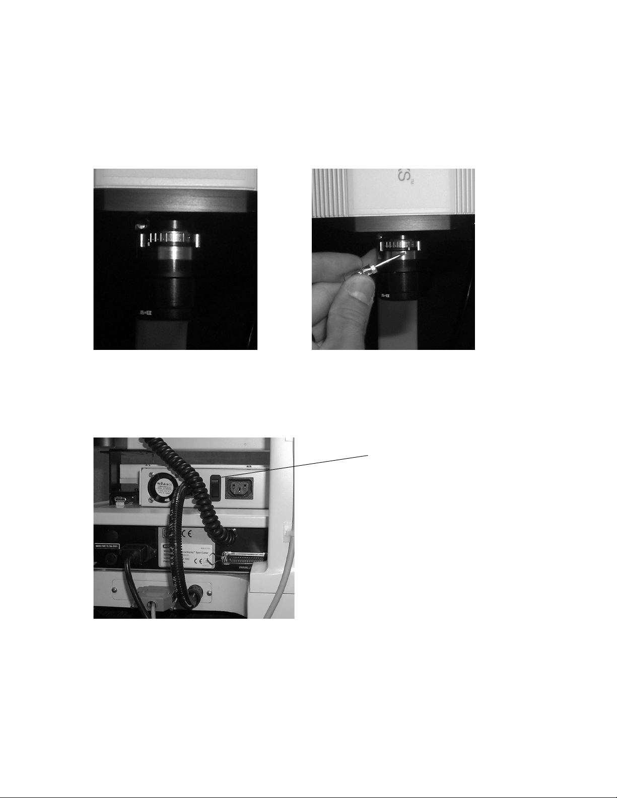
2.4 Installing the Bandpass Filter
1. The bandpass filter is shipped in the Filter Assembly box. It includes a filter holder, a
620/60 nm bandpass filter, and a 0.9 mm hex wrench.
Fig. 9. Lens and Bandpass filter set.
2. Screw the mounted filter into the filter holder. The threads are very fine, so be careful not
to cross the threads.
Fig. 10. Lens and filter on camera.
3. To attach the filter holder to the lens of the camera, slide the filter holder up over the lens
until stops. Using the 0.9 mm hex wrench, gently tighten the setscrew on the side of the
filter holder.
Note:
Bandpass Filter
The bandpass filter is used for both the white light (visible stain) and UV light (fluorescent
stain) modes. Once it is installed, it is not taken off the lens. The only adjustment to the
camera between the two light modes is a change in the aperture from the nearly closed
(f-stop 5.6–16) position for white light, to the open (f-stop 1.4–2.8) position for UV lights.
Lens (included with
the spot cutter)
0.9 mm hex wrench
Filter
Filter holder
Filter holder
Page 10

2.5 Spot Cutter Installation
If you are installing the ProteomeWorks Spot Cutter, catalog number 165-7009, at the same time
as the Fluorescent Enclosure, complete the spot cutter installation steps up to calibration. Place
the spot cutter on the black base mat and level it, but do not add the fluorescent enclosure until
the camera installation is completed. This will make the camera installation easier.
2.6 Installing the Enclosure Cabinet
1. Familiarize yourself with the white/UV light switch and plug-in locations on the back of the
spot cutter before adding the Enclosure using the following picture:
Fig. 11. UV light socket and toggle switch.
2. Place the black base mat on the bench in the location for the spot cutter.
3. Place the spot cutter on the black base mat.
4. Level the spot cutter on the black base mat.
5. Connect all spot cutter cables: camera cable, serial port communication cable, power
cable. Lay the cables out the back of the spot cutter so that they do not overlap each
other at the point the enclosure will cover the cables. The enclosure light seal may be
compromised if the cables are on top of each other and raise the enclosure off the base
mat.
6. It is recommended that two people lift the Enclosure. Lift and tilt the Enclosure (with UV
lights installed but without the door) slightly forward. Lift the enclosure case over the top
of the spot cutter and onto the base mat. Take care that you do not bump the camera. If
you do, continue with the enclosure but re-check the camera position before calibrating.
7. Position the Enclosure and spot cutter so that the spot cutter is towards the back of the
Enclosure box, and the spot cutter is centered within the Enclosure from left to right.
8. Attach the UV lights power cord from the back of the Enclosure into the UV light socket
on the back of the spot cutter. See the above picture for orientation of the 3-prong plug.
9. Re-attach the door to the front of the Enclosure. Line up the hinges and release the two
catches to snap the bolts of the hinge back into place.
2.7 Software Setup
Use the following steps to load the PDQuest software included with the Enclosure onto the
computer in either the Viewer Mode (unlicensed version), or the full feature (licensed version).
7
Light toggle switch
Socket for UV light plug
Page 11

1. Load the software CD into the CD drive and follow the onscreen instructions for
installation.
2. If you are using the "Basic Excision Tool" only (unlicensed PDQuest version), Use the
"Viewer Only" mode of PDQuest. Do not license PDQuest. The Basic Excision Tool will
remain live ongoing, and allow use of the spot cutter, through the Viewer Only mode. The
image analysis demo portion can be used for a 30-day trial, after which you can revert
back to Viewer Only mode, or purchase a license for PDQuest.
3. If you already have a licensed version of PDQuest on the computer, follow the install
instructions and update the registration. To update the registration, if the computer is connected to the Internet, open PDQuest by double clicking on the desktop PDQuest icon,
go to the Help menu option, to "Register", to "Check License". The software will check
the license on record and establish the license for the new version. If the computer is not
connected to the Internet, use the Enter Password option. Enter the password that was
assigned to you for your initial registration. Check that the System ID has not changed. If it
has, call the telephone number listed on the Registration screen.
4. If you are loading the licensed version of PDQuest, follow the onscreen instructions for
installation. Then follow the onscreen instructions for registration of the license.
Section 3
Settings and Calibration
3.1 Setting Aperture for White and UV Lights Settings
Identify the version of lens installed on the spot cutter.
1. The lens has a black thumbscrew to adjust the aperture ring and f-stop numbers on it.
Loosen the thumbscrew.
Aperture settings:
UV lights: f-stop 1.4–2.8
White lights: f-stop 5.6–16
Fig 12. Aperture at f-stop 1.4 for UV light mode. Fig. 13. Aperture at f-stop 16 for white light mode.
8
f-stop 1.4
f-stop 16
Page 12
2. The other version of lens has a silver-notched band and set-screw on the side of the lens. The
white dot below the silver notched band is the aperture adjustment. Moving the white dot
towards the small set-screw closes the aperture. Moving it away from the set-screw opens
the aperture. Use the small, standard head, screwdriver included with the Spot Cutter
accessories to move the white dot on the aperture band away from the set-screw to open the
aperture for UV lights mode. The following figures illustrate this operation.
Fig. 14. Aperture open for UV light imaging. Fig. 15. Aperture closed for white light imaging.
3.2 Toggle Switch for White or UV Lights
To switch from one light mode to the other, the black switch on the back of the ballast box on the
spot cutter is toggled from one position to the other.
Fig. 16. Toggle switch on back of spot cutter.
9
Light toggle switch
Page 13
3.3 Checklist for Operation in UV Light Mode
1. Toggle the white/UV light switch on the back of the ballast box on the spot cutter to the
UV lights position.
2. Check the UV lights by pushing the red "Lights on" button on the lower front right side of
the spot cutter base. The white lights under the platform should NOT come on. If they do
come on under the platform, toggle the back switch to the correct position and re-check
the lights. The UV lights will not come on while the door is open because of the safety
interlock door switch.
3. Open the aperture setting to approximately f-stop 1.4 or the "UV / open" position.
4. Select the "UV on (Fluor)" lights setting in either the Basic Excision Tool or the Integrated
Excision Tool screen.
5. Manually enter an exposure time in the box marked “Time (secs)”. Typically 1 to 40 seconds.
Note:
UV lights Indicator Light
When the UV lights are active and the door is closed, the UV lights are confirmed to be
active with the external amber light on the side of the Enclosure nearest the door handle,
labeled "UV lights in operation". This light will turn on when the lights are actually in use
during image acquisition. The light will otherwise be off indicating that it is safe to open the
door. A safety interlock switch immediately stops power to the UV lights if the door is opened.
Note:
Fluorescent Target
Once the Enclosure is installed, and the light settings and aperture are ready for imaging, a
test image may be desirable with a known target. Included in the Enclosure is a Fluorescent
imaging target. It is the square, clear plastic target with lines, squares and
numbers on it.
When imaged with the UV lights, it should look like this on the computer screen:
Fig. 17. UV light exposure image of fluorescent target.
10
Page 14

This target is also useful for focussing the lens during installation, re-calibration, or for
checking the image acquisition in UV or white light modes.
3.4 Checklist for Operation in White Light Mode
1. Toggle the black switch on the back of the ballast box on the spot cutter to the white light
position. See Figure 16 for location of the toggle switch.
2. Check the white lights by pushing the red “Lights on” button on the lower front right side
of the spot cutter base. If the lights do not come on under the platform, toggle the back
switch to the correct position and re-check the lights.
3. Close the aperture setting to f-stop 5.6–16, or to the white light/closed position.
4. Remove everything (including the cutting mat) from the cutting platform.
5. Close the Enclosure door if it will be closed during imaging of the actual gel.
6. Open the “Focus cutter camera” icon and click on the “Auto-expose” button to automatically
adjust the exposure setting. Click “OK” on the message “Auto-expose complete” and then
click “Stop”.
7. Select the "Light on (Gel)" setting in either the Basic Excision Tool or the Integrated
Excision Tool screen.
3.5 Calibration
After the Enclosure and Spot Cutter set-up is complete, calibrate the spot cutter. Use the following
checklist to ensure that the calibration is successful.
1. Install the lens bandpass filter.
2. Switch the light toggle switch to the white light setting.
3. Check the white lights by pushing the red "Lights on" button on the lower front right side
of the spot cutter base. If the lights do not come on under the platform, toggle the light
toggle switch to the other position and re-check the lights.
4. Change the aperture setting to f-stop 5.6–16, or the white light setting.
5. Remove everything from the cutting platform.
6. Close the door of the Enclosure.
7. Click on the "Focus Cutter camera" icon in the Basic Excision Tool screen.
8. Click on “Auto-expose” to reset the exposure time of the white light image acquisition.
Click “OK” for auto-expose complete, then “Stop” to end Focus mode.
9. Click on the "Calibrate Cutter" icon. A message will come up on the screen asking
whether the calibration is to be performed with
tthhee lleennss ffiilltteerr iinnssttaalllleedd
. Click on "
LLeennss ffiilltteerr
iinnssttaalllleedd
". This must be confirmed so that the fluorescent parts of the software will
become active. This is an important step to ensure proper set-up and final accuracy of the
calibration.
10. The rest of the calibration procedure is described in the general spot cutter manual and in
the on-screen instructions for calibration. For optimum accuracy in both the white light
and UV light modes, leave the bandpass lens filter installed for both UV and white light
imaging and spot cutting. Only the aperture setting is changed between light modes. Spot
accuracy will be adversely affected due to refractive index changes if the filter is removed.
11
Page 15
Section 4
Fluorescent Operation in Basic Excision Tool
The PDQuest version 6.2.1 is very similar to version 6.2.0 in operating the spot cutter. There are
some new function buttons and workflow items based on using the fluorescent enclosure. For a
more complete description of the general function of the spot cutter in Basic Excision Tool mode,
see the ProteomeWorks Spot Cutter manual. The following sections describe the workflow of the
Fluorescent Enclosure items that differ from the white light operation in Basic Excision Tool.
4.1 Calibration and the UV Light Option
The software records the filter set-up with a confirmation button in the calibration. If the "Filter is
not Installed" button is clicked, because the filter has not been installed, then it indicates to the
software that the fluorescent enclosure is not being used. In this case, the UV light option in the
software will be grayed out and is not available. To activate the UV lights, the filter should be
added to the lens and the "Filter is installed" message is clicked at the beginning of the
calibration. This provides a record of how the installation was performed and the hardware that
was in place during calibration.
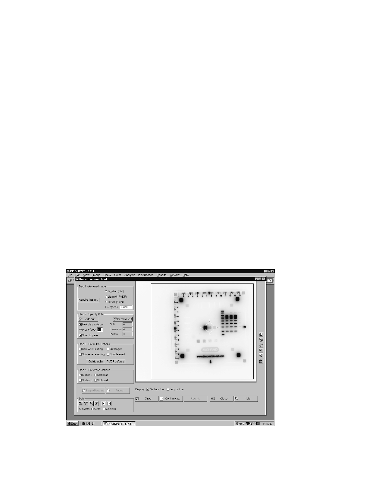
4.2 Acquire Fluorescent Image in Basic Excision Tool
To acquire an image in the Basic Excision Tool screen, select the “UV on (Fluor)” lights setting,
and manually enter an exposure time in seconds. Typical exposure times for SYPRO Ruby stained
2D gels are from 1 to 40 seconds. Start with short exposure times and increase the time as
needed for optimum imaging.
Fig. 18. Example PDQuest version 6.2.1 Basic Excision Tool software with SYPRO Ruby stained 2-D gel.
12
Page 16

4.3 Cutting Spots From Fluorescent Stained Gels in Basic Excision Tool
1. Check that the light toggle switch is in UV lights position.
2. Check that the aperture is open, approximately f-stop 1.4.
3. Place the fluorescent stained gel or membrane blot onto a Gel Sheet (catalog number
165-7018) and place both on the Cutting Mat on the platform of the spot cutter.
4. Place the Gel holding bars on the edges of the gel.
5. Add a thin layer of water to the gel surface.
6. Close the door.
7. Select the "UV on (Fluor)" option in the "Acquire Image" section of the Basic Excision Tool
screen.
8. Enter an exposure time, in seconds
9. Click "Acquire Image". The screen will show a processing box during image acquisition.
The amber light on the side of the Enclosure labeled, "UV lights in operation" will light
during UV illumination. There is a 15 second UV lights warm up step, then the image is
acquired, and then a dark image is acquired.
10. When the image has been acquired, it will fill in the image area of the screen. The image is
automatically inverted by the software to show the gel as dark spots with light background.
If the original fluorescent image with light spots and dark background is desired, use the
transform button to "invert image".
11. If the image does not detect enough spots or is too faint, use the transform function, or
increase the exposure time and re-image the gel or membrane.
12. The blue box shown on the image is the functional cutting area of the spot cutter. Spots
cannot be cut outside this area on the platform. If a spot is selected outside the cutting
area, an error message will occur. The cut mark will be assigned and should be moved
into the cutting region. If spots are outside the cutting area, reposition the gel and acquire
a new image.
4.4 Re-cuts in Basic Excision Tool
The specification for the ProteomeWorks Spot Cutter spot pick-up is greater than 95% effective
at picking up a spot that has been cut from a gel. There may be some spots that have not been
picked up and these can be re-cut. The efficiency of pick up on the second cut is again >95%,
so the spot is reliably picked up the second time. The missed pick ups are detected by the user
looking in the microtiter plate for empty wells. However, with fluorescent gels, the clear gel spot
(with no visible stain) is very difficult to see in the microtiter plate wells. In order to assess the
wells of the microtiter plate, the re-cut message on the screen for the fluorescent light source will
differ from the white light message. Use the following procedure for re-cutting spots in fluorescent
mode:
13
Page 17

1. When UV-Fluorescent imaging has been used on the spot cutter, at the end of the cut run
the software will prompt with, "Confirm cuts?"
Fig. 19. Confirm cuts window.
Answer "Yes" to bring up the following on-screen instructions for imaging the microtiter
plate in UV mode:
Fig. 20. Image Microtiter plate window.
2. Do not move the gel or membrane on the cutting platform
3. Place a clean plastic Gel Sheet on top of the gel
4. Place the microtiter plate on top of the plastic sheet. Note the orientation so that you can
recognize the A1 location.
5. Close the Enclosure door
6. Click on "Acquire image" when the plate is in place. The UV lights will turn on and the
camera will acquire an image with the same exposure time as the first spot cutter image.
14
Page 18

7. Assess the image on the screen for the wells that need to be recut.
Fig. 21. Microtiter plate with fluorescent spots in wells.
Use the Zoom and transform functions on the right side of the "Image Microtiter Plate"
window to get a better view of the microtiter plate wells.
Fig. 22. Microtiter plate after zoom and transform functions applied.
15
Zoom
Transform
Page 19

8. If any of the wells are empty and you want to re-cut those spots, click on “Specify re-cuts.”
Then follow these on-screen instructions:
Fig. 23. Message window before recuts are started.
9. Return the microtiter plate to the plate holder.
10. Remove the plastic sheet from the top of the gel.
11. Do not move the gel. The image and spot selections that were already made still apply to
the gel as long as it does not move.
12. After removing the microtiter plate, click “OK” on the message. The "Image Microtiter
Plate" window will close and an image of the microtiter plate will open in front of the Basic
Excision Tool screen. If you need to resize the window, close the recuts box, resize the
window, make any zoom or transform changes using the icons on the top bar above the
window, then click on the "Recuts" icon to bring the recuts box back up.
Fig. 24. Basic Excision Tool fluorescent mode re-cuts.
13. Enter the well numbers of the missed pick-up spots in the "Re-cuts" box on the screen.
14. Click on "Begin/Resume" after the selections are made.
16
Page 20

4.5 Begin/Resume and Pause Buttons
The Begin cut button has been modified in name to be more descriptive of the different operations that may be used in the spot cutter.
The Pause button will pause the cut run and then give you the option of stopping the cut run
completely or resuming the run. After clicking on "Pause", the spot cutter will continue the cut it is
working on through eject in the microtiter plate and wash wells (if selected) before stopping. The
Pause button will be used for the "Confirm cuts" operation, described next.
4.6 Confirm Cuts
The Confirm cuts button was added to help in checking the cut progress of a fluorescent stained
gel. With visible stained gels, it is easy to look in on the spot cutter to see that the cutting tip is
cutting right on the spot. However, since the spots are not visible without UV illumination in a
fluorescent gel, the "Confirm cuts" operation provides an on-screen method for monitoring the cut
run.
1. After starting the cut run in Basic Excision Tool, let the cut run proceed for 5–10 spot cuts.
2. When you want to check on the cut run, click on "Pause".
3. Click on “YES” to "Confirm Pause run".
4. Click on the "Confirm cuts" button.
5. The camera will acquire a new image and create a floating window on top of the existing
screen.
6. This window will display the gel image with spot "holes" where it has been cut by the spot
cutter. It will also show the overlay circles of the cut targets. The white circles are the spots
that have already been cut, and the green circles are the spots yet to be cut.
Fig. 25. Basic Excision Tool confirm cuts function.
17
Page 21

7. You should be able to see "holes" in the spots in the image within the overlay target circles.
However, there is a + or - 6% to 10% accuracy spec (depending on tip size), so an edge of
the "hole" may be outside the circle and still be within specification.
Note:
The "snap to peak" and "gaussian fit" targeting features center the cuts on the densest
portion of the spot, not necessarily in the visual center of the spot. If the target circles and
cuts are off center, this does not necessarily mean that the targeting and cuts are off the
intended cut.
8. When you have viewed the cuts, click on the “Begin/Resume” button. This will close the new
image window with the overlays, and will prompt for loading the microtiter plate. Click “OK“
when you are ready to resume the cut run.
9. The cut run will resume on the next spot to be cut using the original cut targets.
10. You can repeat the "Confirm cuts" operation as many times as you want during the cut run.
The "confirm cuts" is an option in fluorescent gel cutting. Once you are familiar with targeting and
cutting fluorescent gels, you may or may not continue to use this function.
Section 5
Fluorescent Operation in Integrated Excision Tool
The PDQuest version 6.2.1 is very similar to version 6.2.0 in operating the spot cutter. The main
differences are some new function buttons and workflow items based on using the fluorescent
enclosure. For a more complete description of the Integated Excision Tool using PDQuest image
analysis, see the PDQuest manual. The following sections describe the workflow of the
Fluorescent Enclosure items that differ from the white light operation for the Integrated Excision
Tool.
5.1 Calibration and the UV Light Option
During calibration of the spot cutter, the bandpass filter must be installed if UV/fluorescent imaging
is going to be used for spot cutting. In order to record that the bandpass filter has been installed
for calibration, the first question that comes up in the software during calibration is to confirm that
the lens bandpass filter has been either "Installed" or "Not Installed". Once the system has been
calibrated with the "Filter is Installed" message answered, the "UV on (Fluor)" light option is active.
If the question is answered "Filter is not installed", then the "UV on (Fluor)" light option will not be
active.
18
Page 22

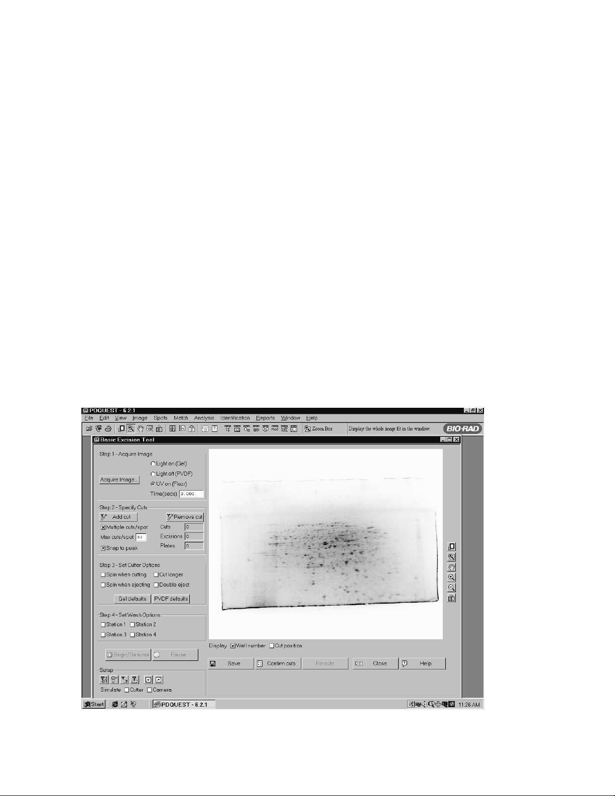
5.2 Acquire Fluorescent Image in Integrated Excision Tool
1. After the Cut List has been selected for spot cutting in the Excision Gel Selection screen,
click "Next".
2. Select the appropriate cutter settings, wash options, microtiter plate name and well number.
3. Click "Align". A thumbnail image of the gel will open on the screen.
4. Place the gel or blot in the same orientation as the original image (shown in the thumbnail
image on the screen) on the spot cutter. If the gel is fluorescent stained, the spots will not
be visible. Therefore, it is recommended to use a physical marker on the gel, such as a
notched or cropped corner of the gel, for orientation. Click “Gel Ready” when it is loaded
on the spot cutter.
5. Select the "UV on (Fluor)" option for fluorescent gels or membranes in the “Align Analysis
and Cutter Images” screen.
Fig. 26. Integrated Excision Tool image alignment screen.
6. Enter the exposure time in seconds. The last used UV exposure time will become the
default for the next UV image, so if you are doing the same type of gel each time you do
not have to change this setting.
7. Check that the light toggle switch is in UV lights position.
8. Check that the aperture is open, or approximately f-stop 1.4.
9. Close the door.
10. Click on the "Acquire Image"button.
11. The amber light on the side of the Enclosure labeled, "UV lights in operation" will light
during UV illumination. There is a 15 second UV lights warm up step, the image is
acquired, and a dark image is then acquired.
12. The newly acquired spot cutter image will come up on the right side of the screen, next to
the original analysis image on the left. Transform as necessary to optimize the images
19
Page 23

13. The image is automatically inverted by the software to show the gel as dark spots with
light background. If the original fluorescent image with light spots and dark background is
desired, use the transform button to "invert image".
14. The "Matching" steps are the same as in the white light mode.
15. If the image does not detect enough spots or is too faint, use the transform function or
increase the exposure time and re-image the gel or membrane.
16. The blue box shown on the image is the functional cutting area of the spot cutter. Spots
cannot be cut outside this area on the platform. If a spot is selected outside the cutting
area, an error message will occur. If a spot to be cut is outside the blue cutting area, reposition the gel and acquire a new image.
17. After matching, click "Begin/Resume" to start the cut run. You will be prompted to put in
the correct microtiter plate before the cuts will begin.
5.3 Re-cuts in Integrated Excision Tool
The specifications for the ProteomeWorks Spot Cutter spot pick-up is greater than 95% effective
at picking up a spot that has been cut from a gel. There may be some spots that have not been
picked up and these can be recut. The efficiency of pick up on the second cut is again >95%, so
the spot is reliably picked up the second time. The missed pick ups are detected by the user
looking in the microtiter plate for empty wells. However, with fluorescent gels, the clear gel spot
(with no visible stain) is very difficult to see in the microtiter plate wells. In order to assess the
wells of the microtiter plate, the re-cut message on the screen for the fluorescent light source will
differ from the white light message. Use the following procedure for re-cutting spots in fluorescent
mode:
1. At the end of the cut run the software will prompt with, "Confirm cuts?"
Fig. 27. Confirm cuts window.
20
Page 24

Answer "Yes" to bring up the following on-screen instructions for imaging the microtiter plate:
Fig. 28. Image microtiter plate window in Integrated Excision Tool.
2. Do not move the gel or membrane on the cutting platform.
3. Place a clean plastic Gel Sheet on top of the gel.
4. Place the microtiter plate on top of the plastic sheet. Note the orientation so that you can
recognize the A1 location.
5. Close the Enclosure door.
6. Click on "Acquire image" when the plate is in place. The UV lights will turn on and the
camera will acquire an image with the same exposure time as the first spot cutter image.
21
Page 25

7. An image of the microtiter plate will open in the "Image Microtiter Plate" window.
Fig. 29. Microtiter plate with fluorescent spots in wells.
Use the Zoom and Transform icons on the right side of the screen to enhance the
microtiter plate image.
Fig. 30. Microtiter plate after zoom and transform functions applied.
22
Zoom
Transform
Page 26

8. If any of the wells are empty and you want to re-cut those spots, click on "Specify re-
cuts." Then follow these on-screen instructions:
Fig. 31. Message window before re-cuts are started.
9. Remove the microtiter plate and put it back in the microtiter plate holder area of the spot
cutter.
10. Remove the plastic sheet from the top of the gel.
11. Do not move the gel. The image and matching that was already done still applies to the
gel as long as it does not move.
12. The image of the microtiter plate will remain on the screen in front of the Integrated
Excision Tool screen.
Fig. 32. Integrated Exicision Tool fluorescent mode re-cuts.
13. The Zoom and Transform icons can be used to enhance the microtiter plate image.
14. Use the scroll bar on the right side of the table to move to the appropriate microtiter plate
well number, located on the left side of the table.
15. Mark the well numbers in the cut list by clicking on the box next to the microtiter plate well
number.
23
Well number
Cut box
indicator
Scroll bar
Page 27

16. Click on "Begin/Resume" after the selections are made. The “MTP Image“ window will
close. All the spots that have been marked for re-cut will now be cut.
5.4 Begin/Resume and Pause Buttons
The Begin cut button has been modified in name to be more descriptive of the different
operations that may be used in the spot cutter.
The Pause button will pause the cut run and then give you the option of stopping the cut run
completely or resuming the run. After clicking on "Pause", the spot cutter will continue the cut it is
working on through eject in the microtiter plate and wash wells (if selected) before stopping. The
Pause button will be used for the "Confirm cuts" operation, described next.
5.5 Confirm Cuts
The Confirm cuts button was added to help in checking the cut progress of a fluorescent stained
gel. With visible stained gels, it is easy to look in on the spot cutter to see that the cutting tip is
cutting right on the spot. However, since the spots are not visible without UV illumination in a
fluorescent gel, the "Confirm cuts" operation provides an on-screen method for monitoring the cut
run.
1. After starting the cut run in Integrated Excision Tool, let the cut run proceed for 5–10 spot
cuts.
2. When you want to check on the cut run, click on "Pause".
3. Click on YES to "Confirm Pause run".
4. Click on the "Confirm cuts" button.
5. The camera will acquire a new image and create a floating window on top of the existing
screen.
6. This window will display the gel image with spot "holes" where it has been cut by the spot
cutter. It will also show the overlay circles of the cut targets. The white circles are the spots
that have already been cut, and the green circles are the spots yet to be cut.
FIg. 33. Integrated Excision Tool Confirm cuts function.
24
Page 28

7. You should be able to see "holes" in the spots in the image within the overlay target circles.
However, there is a + or - 6% to 10% accuracy spec, so an edge of the "hole" may be
outside the circle and still be within specification.
Note:
The "snap to peak" and "gaussian fit" targeting features center the cuts on the densest
portion of the spot, not necessarily in the visual center of the spot. If the target circles and
cuts are off center, this does not necessarily mean that the targeting and cuts are off the
intended cut.
8. When you have viewed the cuts, click on the Begin/Resume button. This will close the new
image window with the overlays, and will prompt for loading the microtiter plate. Click OK
when you are ready to resume the cut run.
9. The cut run will resume on the next spot to be cut with the original cut targets.
10. You can repeat the "Confirm cuts" operation as many times as you want during the cut run.
The "confirm cuts" is an option in fluorescent gel cutting. Once you are familiar with targeting and
cutting fluorescent gels, you may or may not continue to use this function.
25
Page 29

Section 6
Accessories
6.1 Use of Gel Sheets and Gel Positioning
The Gel Sheets (reorder part number 165-7018) are designed to be used with individual gels for
both handling and for protecting the thick plastic Cutting Mat on the spot cutter platform. The Gel
Sheet has a thin protective film on it. Peel this film off the Gel Sheet before use. When the gel is in
a container of water, pick up the gel and place it on the Gel Sheet on the bench. The Gel Sheet
and gel are then placed on the Cutting Mat, positioned towards the right side of the cutting
platform on the spot cutter, near the microtiter plate.
A Gel Holding Bar should be positioned on the top and bottom sides of the gel or blot, resting on
the edge of the gel and on the plastic Gel Sheet.
6.2 Common Re-order Parts
DDeessccrriippttiioonn CCaattaalloogg nnuummbbeerr
Gel Sheets (thin plastic disposable sheets) 165-7018
Cutting Mat (thick plastic sheet - approx. 3–4 mm thick) 165-7019
1.5 mm nominal Cutting Tip 165-7011
1.0 mm nominal Cutting Tip 165-7010
Section 7
Maintenance
7.1 General Upkeep and Cleaning
For general cleaning of the Enclosure, wipe with a damp cloth or sponge. Mild detergents or
ethanol may be used. Do not use any harsh solvents, or cleaners.
7.2 Technical Service
For technical assistance with the system including all hardware and software, contact your local
Bio-Rad office. Spare parts not listed in this document can be ordered by contacting your local
Bio-Rad office.
For inquiries and requests regarding system repair or service, contact your local Bio-Rad office or
distributor. Please have the following details available:
1. Instrument model and catalog number.
2. Serial number (located on the back of the Enclosure).
3. Hardware and software version information.
26
Page 30

7.3 Warranty Information
This warranty statement may vary outside of the continental United States. Please contact your
local Bio-Rad office for the exact terms of your warranty.
Bio-Rad Laboratories warrants to the customer that the ProteomeWorks Spot Cutter Fluorescent
Enclosure (catalog numbers 165-7045/165-7044) will be free from defects in material and
workmanship and will meet all of the performance specifications for a period of one year from the
date of shipment. This warranty covers all parts and components of the instrument except those
such as gaskets, o-rings, batteries, and other items of normal wear that require frequent
replacement. This warranty does not cover items broken or damaged, including glass or platinum
electrodes, by improper handling or use.
If any defects should occur during this period, Bio-Rad Laboratories will either replace or repair
the defective parts free of charge. For the exact terms of warranty, please see the Instrument
Warranty Card. In the event that the system must be returned to the factory for repair under
warranty, the instrument must be packed and returned in its original shipping container. If this is
not available, contact Bio-Rad Technical Service for instructions. Bio-Rad shall not be liable for
any incidental, special or consequential loss, damage or expense, directly or indirectly arising from
use of the ProteomeWorks Spot Cutter Fluorescent Enclosure.
Bio-Rad makes no warranty whatsoever in regard to products or parts furnished by third parties,
such being subject to the warranty of their respective manufacturers. Service under this warranty
shall be requested by contacting your nearest Bio-Rad office.
This warranty does not extend to any instruments or parts thereof that have been subject to misuse, neglect, or accident, or that have been modified or serviced by anyone other than Bio-Rad
or its representative, or that have been used in violation of Bio-Rad instructions. It also does not
extend to instruments or parts thereof that have been used with fittings or other spare parts not
authorized by Bio-Rad Laboratories, that are interfaced to inappropriate external devices, that
have been exposed to inappropriate solvents, cleaning agents or samples. The warranty also
does not cover instrument damage resulting from facility problems such as power surges.
The foregoing obligations are in lieu of all other obligations and liabilities including negligence and
all warranties of merchantability, fitness for a particular purpose otherwise expressed or implied in
fact or by law, and state Bio-Rad's entire and exclusive liability and buyers exclusive remedy for
any claims or damages in connection with the furnishing of goods or parts, their design, suitability
for use installation and operation. Bio-Rad Laboratories will in no event be liable for any special,
incidental or consequential damages whatsoever, and Bio-Rad's liability under no circumstances
will exceed the contract price for the goods for which liability is claimed.
27
Page 31

System Records
Serial Number
Date of Purchase
Purchase Order
Number
Notes
Service Record
Date Description of Problem Name Signature
28
Page 32

4006206 Rev B
S
cience
p
e
a
a
4
dFrance
ael
ea
ds
9
Swede
8
1
US/EG
A
Bio-Rad
.
Laboratories, Inc
Life
Grou
ulletin 0000
Rev
Web sit
Also in: Australi
Brazil
Denmark Finlan
Isr
Italy Japan
Kor
The Netherlan
n Ph. 46 (0)8-55 51 27 00, Fx. 46 (0)8-55 51 27 80 SwitzerlandPh. 061-717-9555, Fx. 061-717-9550 United Kingdom Ph. 0800-181134, Fx. 01442-25911
Austri
Belgium Ph. 09-385 55 11, Fx. 09-385 65 5
Ph. 01 47 95 69 65, Fx. 01 47 41 9133
Ph. 47-23-38-41-30, Fx. 47-23-38-41-3
00-000 0000 Sig 010
 Loading...