

Page 1

Bio-Rad Laboratories
2000 Alfred Nobel Dr.
Hercules, CA 94547
1-800-424-6723
4110007 Rev C
Page 2

Instruction Manual
Catalog # 171-203000
For use with Bio-Plex Manager Software Version 3.0 and MCV plate II
or
For use with Bio-Plex Manager Software Version 2.0 and MCV plate
For technical service, call your local Bio-Rad office, or
in the US, call 1-800-4BIORAD (1-800-424-6723)
For research use only. Not for diagnostic procedures.
Page 3

Table of Contents
Section 1 Introduction . . . . . . . . . . . . . . . . . . . . . . . . . . . . . . . . . . .1
Section 2 Product Description . . . . . . . . . . . . . . . . . . . . . . . . . . . .2
Section 3 Specifications . . . . . . . . . . . . . . . . . . . . . . . . . . . . . . . . .3
Section 4 Storage and Handling . . . . . . . . . . . . . . . . . . . . . . . . . . .3
Section 5 Principle of Optics Validation . . . . . . . . . . . . . . . . . . . .4
Section 6 Principle of Reporter Channel Validation . . . . . . . . . . .4
Section 7 Principle of Classify Validation . . . . . . . . . . . . . . . . . . .7
Section 8 Principle of Fluidics Validation . . . . . . . . . . . . . . . . . .8
Section 9 Procedure for Bio-Plex Manager 3.0/MCV plate II . . .9
9.1 One-Step Procedure for all Validation Parameters . . . . . . . . .9
9.2 Validation of Optics Alignment . . . . . . . . . . . . . . . . . . . . . .11
9.3 Validation of Fluidics Integrity . . . . . . . . . . . . . . . . . . . . . . .13
9.4 Validation of Reporter Channel Performance . . . . . . . . . . . .15
9.5 Validation of Classify Efficiency . . . . . . . . . . . . . . . . . . . . . .16
9.6 Generating a Validation Report . . . . . . . . . . . . . . . . . . . . . .18
9.7 Validation Report Example . . . . . . . . . . . . . . . . . . . . . . . . .19
Section 10 Procedure for Bio-Plex Manager 2.0/MCV plate . . . .21
10.1 Validation of Optics Alignment . . . . . . . . . . . . . . . . . . . . . .21
10.2 Validation of Reporter Channel Performance . . . . . . . . . . . .23
10.3 Validation of Classify Efficiency . . . . . . . . . . . . . . . . . . . . . .25
10.4 Validation of Fluidics Integrity . . . . . . . . . . . . . . . . . . . . . . .26
10.5 Generating a Validation Report . . . . . . . . . . . . . . . . . . . . . .28
10.6 Validation Kit Worksheet and Report
Section 11 Troubleshooting Guide . . . . . . . . . . . . . . . . . . . . . . . . .32
Section 12 Ordering Information . . . . . . . . . . . . . . . . . . . . . . . . . .32
Section 13 Reference . . . . . . . . . . . . . . . . . . . . . . . . . . . . . . . . . . .33
Form Examples . . . . . . . . . . . . . . . . . . . . . . . . . . . . . . . . .28
Page 4

Section 1
Introduction
Qualification of analytical instruments is a formal process of documenting that an
instrument is fit for its intended use and that it is kept maintained and calibrated.
The Bio-Plex validation kit is used for operational qualification (OQ) of the Bio-Plex
protein array system. The validation kit is designed to validate the operation of all of
the primary components of the system and is a valuable tool that allows the user to
discriminate between assay and instrumentation problems.
The Bio-Plex validation kit consists of beads to evaluate the following components
of the Bio-Plex protein array system: 1) optics alignment, 2) integrity of fluidics, 3)
reporter channel performance, and 4) classify efficiency. A brief definition of the
parameter and the principle of each procedure is described, along with complete
procedures for evaluating each of the primary components. An explanation of the
potential impact of each process on a typical Bio-Plex cytokine assay is included to
assist the user in assay troubleshooting and development.
NNOOTTEE:: BBiioo--PPlleexx MMaannaaggeerr 33..00 rreeqquuiirreess MMCCVV ppllaattee IIII ((CCaatt## 117711--220033003311)) ffoorr uussee wwiitthh
tthhiiss VVaalliiddaattiioonn KKiitt,, sseeee SSeeccttiioonn 99..
BBiioo--PPlleexx MMaannaaggeerr 22..00 rreeqquuiirreess MMCCVV ppllaattee ((CCaatt## 117711--220033003300)) ffoorr uussee wwiitthh tthhiiss kkiitt,,
sseeee SSeeccttiioonn 1100.. BBiioo--PPlleexx MMaannaaggeerr 22..00 ddooeess nnoott aallllooww uussee ooff fflluuiiddiiccss 11 aanndd fflluuiiddiiccss
22 bbeeaaddss.. TThhiiss sstteepp iiss oommiitttteedd,, ffoollllooww SSeeccttiioonn 1100 iinnssttrruuccttiioonnss..
For research use only. Not for diagnostic procedures.
1
Page 5

Section 2
Product Description
The following reagents are included in the Bio-Plex validation kit:
Reagent Quantity
Optics validation bead set:
Optics beads 1 and 2 2 x 10 ml black bottles
5
(1x10
beads/ml)
Fluidics validation bead set:
Fluidics bead 1 1 x 10 ml black bottle
5
(1x10
beads/ml)
Fluidics bead 2 1 x 10 ml black bottle
Reporter validation bead set:
Reporter blank, 1, 2, 3, 4, and 5 6 x 10 ml white bottles
5
(1x10
beads/ml)
Classify validation bead set:
Classify bead 34, 38, 54, 73, 77 5 x 10 ml black bottles
5
(1x10
beads/ml)
NNOOTTEE:: TThhee vvaalliiddaattiioonn kkiitt mmuusstt bbee uusseedd ffoolllloowwiinngg CCAALL22 ccaalliibbrraattiioonn uussiinngg tthhee RRPP11
hhiigghh ttaarrggeett vvaalluuee.. VVaalliiddaattiioonn sshhoouulldd bbee ppeerrffoorrmmeedd iimmmmeeddiiaatteellyy ffoolllloowwiinngg
ccaalliibbrraattiioonn..
The following materials are required but not supplied:
Bio-Plex MCV plate
Bio-Rad catalog #171-203031 MCV plate II, use with Bio-Plex Manager 3.0,
Bio-Rad catalog #171-203030 MCV plate, use with Bio-Plex Manager 2.0
Bio-Plex Protein Array System
Bio-Rad catalog #171-000001, 171-000003, or 171-000005
Bio-Plex Calibration Kit
Bio-Rad catalog #171-203060
mini vortexer
sterile distilled water
70% isopropanol
10% bleach
bulb pipets
2
Page 6

Section 3
Specifications
General specifications for the validation kit are listed below. Certain specifications
for the Bio-Plex validation kit may differ from lot to lot. For a complete listing of the
current specifications, please refer to the package insert provided with your
validation kit.
Parameter Specification
Optics Validation
DD mean See insert
CL1 mean See insert
CL1 CV% (Coefficient of Variable) 3–7%
CL2 mean See insert
CL2 CV% 4–8%
RP1 mean See insert
RP1 CV% 5–10%
Fluidics Validation
% carryover < or = 4.0%
Reporter Validation
Dynamic range 4.15–4.28
Linearity >0.995
Slope of response 0.0593–0.0799
Accuracy of response >90%
Sensitivity <200 MESF
Classify Validation
Classify Bead 34, 38, 54, 73, 77 >80.0%
DD Efficiency
% Efficiency > or = 75%
Section 4
Storage and Handling
The Bio-Plex validation kit beads are stable if stored at 4°C protected from light.
When using the Bio-Plex validation kit, remove beads from 4°C storage and
dispense into the MCV plate. Return to 4°C storage immediately following use to
preserve shelf life. All components are guaranteed for 6 months from the date of
purchase when stored as specified in this manual.
3
Page 7

Section 5
Principle of Optics Validation
Principle
The Bio-Plex array reader is a laser-based fluorescence detection system containing
sensitive optics components. Alignment of the laser/optics system is critical for
optimal instrument performance. A method for the assessment of the optics
alignment is included in the validation kit. Acceptable specifications for the
alignment procedure are listed in the product insert.
Impact on Assay Performance
The alignment of the optics bench of the Bio-Plex array reader is critical for proper
assay performance. Misalignment of the reporter optics path can result in 1)
reduced assay sensitivity or 2) poor well-to-well assay precision. Misalignment of
the classification optics path can lead to 1) increased read times or 2)
misclassification of one assay into another, leading to false positive or negative
results. Correlation studies have been performed to determine the direct effect of
misalignment on assay performance.
Section 6
Principle of Reporter Validation
Principle
The reporter (RP1) channel is the fluorescence channel used for assay quantitation
(See Bio-Plex system hardware manual for more information regarding the principle
of Bio-Plex technology). Therefore, validation of this component of the Bio-Plex
system is a critical part of operational qualification. R-phycoerythrin (R-PE) is the
primary reporter molecule used in Bio-Plex assays. A series of beads dyed with
varying intensities of a fluorochrome spectrally matched to R-phycoerythrin are used
for this procedure. Each of the reporter beads has been assigned a specific
intensity value corresponding to the number of fluorescent R-PE molecules. These
units of fluorescent measure are known as molecules of equivalent soluble
fluorescence (MESF). MESF units allow direct correlation of instrument performance
to a typical assay using R-PE as the indicator molecule. The primary reporter
channel performance parameters are as follows: dynamic range, linearity, accuracy
of reporter channel response, sensitivity, and slope of the response. Each of these
parameters is related directly to the performance of the Bio-Plex array reader and
has defined acceptable specifications. Definitions for the parameters and the
applicability to a typical assay performed on the Bio-Plex array reader are listed
below. If any of the parameters are not within the specified range, contact Bio-Rad
Technical support for assistance.
4
Page 8

Dynamic Range of Reporter Channel
Definition
The dynamic range is the calculated number of decades covered by the log
amplifier from the slope and the histogram scale. The available range of channels
on the Bio-Plex array reader is 4.5 log amp decades or 32,767 relative linear
channels. The acceptable dynamic range of fluorescence measured by the Bio-Plex
array reader using the Bio-Plex reporter beads is 4.15–4.28.
Impact on Assay Performance
The dynamic range of the Bio-Plex array reader is 4.5 log amp decades or 32,767
relative linear channels. It is desirable for the range of the instrument to be greater
than the range of an assay. If the dynamic range of the instrument is less than that
of an assay, the range of quantitatable analyte may be limited. This parameter will
guide the user in defining the instrument versus the assay dynamic range
limitations.
Linearity of Reporter Channel
Definition
The reporter validation bead set is utilized to construct a plot where the reporter
channel median fluorescence intensity values are plotted against the corresponding
assigned MESF values. Instrument linearity is expressed as the coefficient of
determination or R-squared (R
Impact on Assay Performance
2
) value. The R2value must be >0.995.
The linearity of the instrument response may directly affect a typical standard or
calibration curve in a Bio-Plex assay, thereby impacting the unknown values
extrapolated from that curve. If the R
2
value is not within acceptable limits, it may
be necessary to realign the optics or check the response of the reporter
photomultiplier tube.
Accuracy of Reporter Channel Response
Definition
The accuracy of the reporter channel response is a more stringent measurement of
the linearity than the R
2
value. Simply stated, the accuracy of the reporter channel
response is the percent difference that the regression line is away from the actual
MESF value data points. The desired accuracy value is >90%.
Impact on Assay Performance
Since accuracy is also a measurement of the linearity of the instrument response,
the same principles that apply to linearity also apply to accuracy of the reporter
channel response. Accuracy values <90% could impact assay performance. The
accuracy data is evaluated in combination with optics alignment to determine if the
Bio-Plex array reader will perform according to specifications. It is possible for the
accuracy value to fall out of specification before the linearity parameter. This is
expected due to the fact that the accuracy parameter is a more sensitive
measurement of linearity than the R
2
value. These data are correlated with optics
alignment data as well as assay performance to determine when the array reader
will not perform according to specifications.
5
Page 9

Slope of the Reporter Channel Response
Definition
The slope of the regression line resulting from the plotting of reporter channel
mean fluorescent values against assigned reporter channel validation bead MESF
values is related to the dynamic range of the instrument. The slope of the
regression line is a function of the response of the reporter channel
photomultiplier tube. The acceptable range for the slope is 0.0593–0.0799.
Impact on Assay Performance
The slope of the regression line is directly related to the dynamic range of the
instrument. The slope yields direct information about the response of the
photomultiplier tube. If the photomultiplier tube signal saturates at low
fluorescence values, the dynamic range of the instrument is affected. The slope
of the line impacts the dynamic range and the range in turn impacts the
quantitatable range of an assay. If the validation kit yields a value for the slope
that is not within specifications, assay results could be adversely affected.
Sensitivity of Reporter Channel
Definition
Every instrument has an inherent level of noise due primarily to the electronics.
The sensitivity of the Bio-Plex array reader is defined as the lowest detectable
signal above instrument noise. Noise can be attributed to the laser, the
photomultiplier tube, the amplification electronics or the fluidics. The acceptable
sensitivity using the Bio-Plex array reader is <200 MESF.
Impact on Assay Performance
The sensitivity using the Bio-Plex validation kit is expressed in terms of MESF.
The fluorescence is traceable to R-PE, the primary molecule used in Bio-Plex
assays. The typical background or zero standard of a Bio-Plex cytokine assay
falls at a median fluorescence intensity of 100. The background of a "blank" bead
from the validation kit exhibits a median fluorescence intensity of 8. A plot of the
median RP1 fluorescence intensity versus the MESF units illustrates that the
instrument is approximately 10 times more sensitive than a Bio-Plex cytokine
assay (See Figure 1). This is a desired result, as the sensitivity of the instrument
should not directly limit assay sensitivity.
6
Page 10
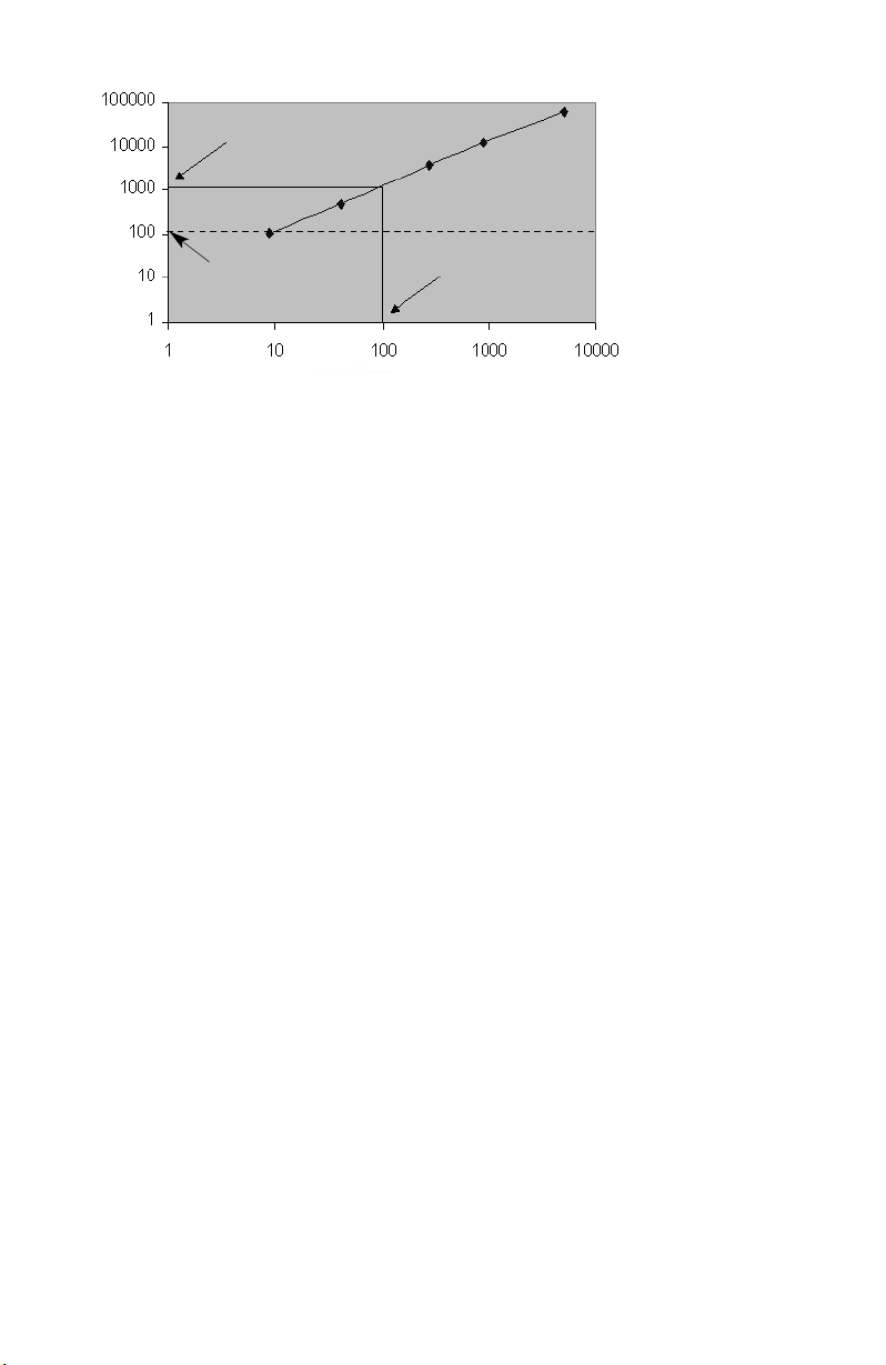
Assay MESF
Reader sensitivity
MESF (R-PE)
RP1 Channel
Fig. 1. Assay vs. instrument sensitivity.
Assay Background
Section 7
Principle of Classify Validation
Principle
Bio-Plex technology relies on the ability of the Bio-Plex array reader to
discriminate between assay beads impregnated with varying ratios of 2
fluorescent dyes. This is the concept whereby multiplexing within a single well
may occur. The periodic evaluation of the classify efficiency is necessary to
complete the Bio-Plex array reader qualification process. A series of beads with
varying ratios of the classification dyes are analyzed on the Bio-Plex array reader
and the efficiency of multiplexing is quantitated. A classify efficiency of >80% is
required for optimal results. DD Efficiency is a measure of the percentage of the
Classify beads that fall within the DD Gates. Greater than 75% of the beads
should fall within the gates for optimal results.
Impact on Assay Performance
Inefficient classification of beads may have several potential effects on an assay. If
a bead region exhibits a classify efficiency of less than 80%, the read time of a
96-well plate may be increased. The Bio-Plex array reader tabulates a specified
number of defined events in each region for each well sampled. If the percentage
of beads within a specific region is low, the time required to count is increased,
therefore the total time to read an entire plate is prolonged. Extremely prolonged
assay read times could impact well-to-well precision, since the kinetics of a
sandwich assay, for example, are not 100% stable over a period of 3–5 hrs.
Another potential impact of inefficient classification is the misclassification of one
assay bead into another bead region. This could yield false positive or negative
results for a particular assay. A DD efficiency value less than 75% may increase
the read time of the assay and affect results in the same manner as a low classify
efficiency.
7
Page 11

Section 8
Principle of Fluidics Validation
Principle
The fluidics system of the Bio-Plex suspension array reader requires routine
maintenance to prevent clogging and other malfunctions. Strict adherence to the
maintenance procedures is mandatory for optimal instrument performance. An
assessment of the integrity of the fluidics is automatically performed in the
Fluidics Validation procedure. In the fluidics validation test, a sample of beads is
analyzed followed by a sample of buffer to assess the carryover of beads from
one well to another. This procedure should be performed once per week to
ensure that assay results are not adversely affected. The fluidics path, including
the sample needle must be completely free of debris and excess beads for
optimal array reader performance.
Impact on Assay Performance
If a system is exhibiting a high level of carryover, due to valve malfunction or
partially clogged sample needle, a significant percentage of beads may be carried
over from one well to another. This phenomenon may adversely affect the median
fluorescent intensity values. For example, if a well with a high median fluorescent
intensity (FI) is read immediately prior to a well with a low median FI, the signal in
the well with the low fluorescent intensity may shift upward. This phenomenon
only occurs in extreme cases since the median fluorescent intensity statistic is
robust and is not easily shifted by the introduction of a population of beads with a
significantly different median FI.
8
Page 12

Section 9
Procedure for Bio-Plex Manager 3.0 and
MCV plate II
Introduction
This section provides instructions for use of the Bio-Plex Validation Kit 3.0 with
Bio-Plex Manager version 3.0 and MCV plate II. Bio-Plex Manager now provides
a fully automated validation routine that sequentially performs all the validation
tests without further user intervention. To perform all validations in a single step,
follow instructions in Section 9.1. If you wish to perform an individual validation
routine, these instructions are provided in Sections 9.2–9.5.
9.1 One-Step Procedure for all Validation Parameters
Procedure
1. Turn on the Bio-Plex array reader, microplate platform, and computer as
specified in the Bio-Plex hardware and Bio-Plex Manager user manuals.
2. Perform start-up procedure as directed.
3. Calibrate Bio-Plex array reader using CAL 1 and CAL2 beads found in the
Bio-Plex Calibration Kit according to the Bio-Plex Manager software manual.
NNoottee:: BBee ssuurree ttoo ccaalliibbrraattee iimmmmeeddiiaatteellyy bbeeffoorree vvaalliiddaattiioonn.. UUssee tthhee HHiigghh RRPP11
TTaarrggeett ffoorr CCAALL22 ccaalliibbrraattiioonn..
4. Remove all validation bead sets from 4°C storage and vortex each and every
bottle for 30 sec. This is very important for proper validation.
Bio-Plex Manager 3.0 and MCV Plate II Instructions
9
Page 13

5. Select Instrument from the main menu. Select Validation from the pull-down
menu. The following dialog box appears: (Figure 2A)
Fig. 2A. Main validation dialog.
6. Enter user name and control number. Select All. Select OK. The following
dialog appears: (Fibure 2B)
Fig. 2B.
Bio-Plex Manager 3.0 and MCV Plate II Instructions
10
Page 14

7. Place 5 drops each of bead into the respective wells on the MCV plate II
(see Figure 3 below or Figure 2B). Store beads at 4°C as soon as possible
after use. Protect the beads from light.
Fig. 3. MCV plate II.
8. Select the Eject button in the dialog box to eject the plate holder.
9. Place the MCV plate II in the microplate platform.
10. Select OK to begin all validation procedures.
9.2 Validation of Optics Alignment
Procedure
1. Turn on the Bio-Plex array reader, microplate platform, and computer as
specified in the Bio-Plex hardware and Bio-Plex Manager user manuals.
2. Perform start-up procedure as directed.
3. Calibrate Bio-Plex array reader using CAL1 and CAL2 beads found in the
Bio-Plex Calibration Kit according to the Bio-Plex Manager software manual.
NNoottee:: BBee ssuurree ttoo ccaalliibbrraattee iimmmmeeddiiaatteellyy bbeeffoorree vvaalliiddaattiioonn.. UUssee tthhee HHiigghh RRPP11
TTaarrggeett ffoorr CCAALL22 ccaalliibbrraattiioonn..
4. Remove the optics validation bead set from 4°C storage and vortex each
bottle for 30 sec.
5. Place 5 drops each of optics beads 1 and 2 into the respective wells on the
MCV plate II.
6. Store optics beads at 4°C as soon as possible after use. Protect the beads
from light.
7. Select Instrument from the main menu. Select Validation from the pull-down
menu.
Bio-Plex Manager 3.0 and MCV Plate II Instructions
11
Page 15

8. Enter user name and control number. Select Optics. Select OK. The
following dialog appears: (Figure 4).
Fig. 4.
9. Select the Eject button in the dialog box to eject the plate holder.
10. Place the MCV plate II in the microplate platform.
11. Select OK to begin the optics validation procedure.
12. When the procedure has been completed, the results will be displayed in a
dialog box as shown in Figure 5.
13. The results will also be logged into a validation log in Bio-Plex Manager. To
access this log, select View from the main menu then Validation Log. Each
type of validation is stored in a separate log for the purpose of tracking data
over time. See Bio-Plex Manager 3.0 user manual for more information on
using the validation log.
Bio-Plex Manager 3.0 and MCV Plate II Instructions
12
Page 16

Fig. 5. Optics validation results.
14. Acceptable optics validation specifications:
Parameter Specification
DD median See insert
CL1 median See insert
CL1 CV% 3–7%
CL2 median See insert
CL2 CV% 4–8%
RP1 median See insert
RP1 CV% 5–10%
If any values do meet specification, repeat the procedure. If values are again
not within specifications, contact Bio-Rad technical support for assistance.
9.3 Validation of Fluidics Integrity
Procedure
1. If not already done, follow the procedure for start-up and calibration of the
Bio-Plex system.
2. Select instrument, then validation from the main menu and select fluidics in
the dialog box.
3. Enter user name and control number. Select OK, the following dialog box
appears (Figure 10).
Bio-Plex Manager 3.0 and MCV Plate II Instructions
13
Page 17

Fig. 6. Fluidics validation dialog.
4. Add 5 drops each of fluidics beads 1 and 2 to the designated wells on the
MCV plate II.
5. Select the Eject button in the dialog box to eject the plate holder.
6. Place the MCV plate II in the microplate platform.
7. Select OK to begin the fluidics validation procedure.
8. When the procedure has been completed, results will appear in a dialog box
as shown in Figure 11:
Fig. 7. Fluidics validation results.
9. Acceptable fluidics validation value.
% carryover < or = 4.0%
Note: If value is not within range, repeat the procedure. If value again is not within
the specification, contact Bio-Rad technical support for assistance.
Bio-Plex Manager 3.0 and MCV Plates II Instructions
14
Page 18

9.4 Validation of Reporter Channel Performance
Procedure
1. If not already done, follow the procedure for start-up and calibration of the
Bio-Plex system.
NNOOTTEE:: BBee ssuurree ttoo ccaalliibbrraattee iimmmmeeddiiaatteellyy bbeeffoorree vvaalliiddaattiioonn.. UUssee tthhee HHiigghh RRPP11
TTaarrggeett vvaalluuee ffoorr tthhee CCAALL22 ccaalliibbrraattiioonn..
2. Remove the reporter validation bead set from 4°C storage and vortex each
bottle for 30 sec.
3. Place 5 drops of each reporter bead into the corresponding reporter well
labeled as B (blank), 1, 2, 3, 4, and 5 in the MCV plate II (see Figure 2).
4. Store reporter beads at 4°C as soon as possible after use. Protect the beads
from light.
5. Fill the DI H
O reservoir with water.
2
6. Select Instrument from the main menu. Select Validation from the pull-down
menu. A dialog will appear. Enter user name and control number. Select
Reporter Validation. Select OK. The following dialog appears: (Figure 5)
Fig. 8. Reporter validation dialog.
7. Select the Eject icon in the dialog box to eject the plate holder.
8. Place the MCV plate II in the microplate platform.
9. Select OK to start the reporter validation procedure.
10. When the procedure is completed, values will be displayed in a dialog box as
shown below: (Figure 7)
Bio-Plex Manager 3.0 and MCV Plates II Instructions
15
Page 19

Fig. 9. Reporter validation results.
11. The results will also be logged into a validation log in Bio-Plex Manager. See
Bio-Plex Manager user manual for more information on using the validation log.
12. Repeat procedure if values are not within specifications. If any values are
again not within acceptable ranges, contact Bio-Rad technical service for
assistance.
13. Acceptable reporter validation specifications:
Parameter Specification
Dynamic Range 4.15–4.28
Linearity >0.995
Slope 0.0593–0.0799
Accuracy >90%
Sensitivity <200 MESF
9.5 Validation of Classify Efficiency
Procedure
1. If not already done, follow the procedure for start-up and calibration of the
Bio-Plex system.
2. Remove the classify validation bead set from 4°C storage and vortex each
bottle for 30 sec.
3. Place 5 drops of each classify bead into the corresponding classify well
labeled as 34, 38, 54, 73, and 77 in the MCV plate II (see Figure 2).
4. Store stock vials at 4°C as soon as possible after use. Protect beads from
light.
Bio-Plex Manager 3.0 and MCV Plate II Instructions
16
Page 20

5. Select Instrument from the main menu. Select Validation from the pull-down
menu.
6. Enter the User name and control number. Select classify validation. Select
OK. The following dialog box appears. (Figure 8)
7. Select the Eject button to eject the plate holder.
Fig. 10. Classify validation.
8. Place the MCV plate II on the microplate platform.
9. Select OK to start the classify validation procedure.
10. When the procedure is completed, values will be displayed in a dialog box as
shown below (Figure 9). The classify efficiency and DD efficiency results may
be accessed in this view.
Fig. 11. Classify validation results.
Bio-Plex Manager 3.0 and MCV Plate II Instructions
17
Page 21

11. The results will also be logged into a Validation Log in Bio-Plex Manager. To
access this log, select view from the main menu then Validation Log. Each
type of validation is stored in a separate log for the purpose of tracking data
over time. See Bio-Plex Manager 3.0 user manual for more information on
using the validation log.
12. Acceptable classify efficiency values:
Classify Bead Specification
34 >80.0%
38 >80.0%
54 >80.0%
73 >80.0%
77 >80.0%
Note: If any values do not meet specifications, repeat the procedure. If
values are again not within specifications, contact Bio-Rad technical service
for assistance.
9.6 Generating a Validation Report
Procedure
The results from each validation procedure are sent to a validation log in Bio-Plex
Manager 3.0. This log may be used to create individual reports as well as track
multiple validation results over time. Each type of validation is logged into a
separate view: optics validation, fluidics validation, reporter validation and classify
validation. You may maneuver through each of the views using either the main
menu items or the toolbar icons. The specifications for each control number of
the validation kit are also shown in a separate window below the results. If All
validation was selected, an entry matching the specific date and time will appear
in each of the validation logs. All of the validation results for a specific date and
time will be included in a created report. The entire log may be printed by
selecting Print then Results from the main menu.
A general procedure for creating a report from the Validation log is shown below.
For more detailed instructions on the use of the validation log, consult the BioPlex Manager 3.0 user manual.
1. Open Bio-Plex Manager 3.0 software by clicking on the application icon on
the desktop.
2. Select View from the main menu then select Validation Log from the
pulldown menu. The validation log will open.
Bio-Plex Manager 3.0 and MCV Plate II Instructions
18
Page 22

3. Choose the desired validation log by using the main menu or the toolbar icons
for optics, fluidics, reporter and classify validation.
4. Click on the desired entry in the validation log. The selected row will be
highlighted in black.
5. Select the create report icon. A report will automatically be generated in
Microsoft Excel.
6. Print the report in Excel by selecting File then Print from the main menu.
Alternatively, you may use the print button in Excel.
9.7 Validation Kit Worksheet and Report Form Examples
The following is a sample validation report from Bio-Plex Manager. Note that the
values included here are for demonstration purposes only. Consult your product
insert for values specific to your product control number..
Bio-Plex Manager 3.0 and MCV Plates II Instructions
19
Page 23

Bio-Plex Manager 3.0 and MCV Plates II Instructions
20
Page 24

Section 10
Procedure for Bio-Plex Manager 2.0
and MCV Plate
10.1 Validation of Optics Alignment
Procedure
1. Turn on the Bio-Plex array reader, microplate platform, and computer as
specified in the Bio-Plex hardware and Bio-Plex Manager user manuals.
Note: Be sure to calibrate immediately before validation. Use the High RP1
Target value for CAL2 calibration.
2. Perform start-up procedure as directed.
3. Calibrate Bio-Plex array reader using CAL1 and CAL2 beads found in the
Bio-Plex calibration kit according to the Bio-Plex Manager software manual.
4. Remove the optics validation bead set from 4°C storage and vortex each
bottle for 30 sec.
5. Place 5 drops of optics bead 1 into the first of the 3 optics wells labeled with
"1" on the MCV plate (see Figure 2 below). Leave the 2 remaining wells
labeled with "1" empty.
Fig. 12. MCV plate.
6. Place 5 drops of optics bead 2 into the first of the 3 optics wells labeled with
2 on the MCV plate. Leave the 2 remaining wells labeled with "2" empty.
7. Store optics beads at 4°C as soon as possible after use. Protect the beads
from light.
Bio-Plex Manager 2.0 and MCV Plate Instructions
21
Page 25

8. Select Instrument from the main menu. Select Validation from the pull-down
menu. Select Optics from the pop-up menu. The following dialog box
appears:
Fig. 13. Optics validation dialog.
9. Select the Eject button in the dialog box to eject the plate holder.
10. Place the MCV plate in the Bio-Plex microplate platform.
11. Select OK to begin the optics assessment procedure.
12. When the procedure has been completed values will be displayed in a dialog
box as shown on the next page.
13. Record the values for each optics validation parameter in the validation kit
worksheet provided with the validation kit.
Bio-Plex Manager 2.0 and MCV Plate Instructions
22
Page 26

Fig. 14. Optics validation results.
14. Acceptable optics validation specifications:
Parameter Specification
DD median See insert
CL1 median See insert
CL1 CV% 3–7%
CL2 median See insert
CL2 CV% 4–8%
RP1 median See insert
RP1 CV% 5–10%
If any results are not within the acceptable specifications, please contact
Bio-Rad technical service.
If any values do meet specification, repeat the procedure. If values are again
not within specifications, contact Bio-Rad technical service for assistance.
10.2 Validation of Reporter Channel Performance
Procedure
1. If not already done, follow the procedure for start-up and calibration of the
Bio-Plex system. Note: Be sure to calibrate immediately before validation.
Use the High RP1 Target value for CAL2 calibration.
2. Remove the reporter validation bead set from 4°C storage and vortex each
bottle for 30 sec.
Bio-Plex Manager 2.0 and MCV Plate Instructions
23
Page 27

3. Place 5 drops of each reporter bead into the corresponding reporter well
labeled as B (blank), 1, 2, 3, 4, and 5 in the MCV plate (see Figure 2).
4. Store reporter beads at 4°C as soon as possible after use. Protect the beads
from light.
5. Fill the DI H
O reservoir with water.
2
6. Select Instrument from the main menu. Select Validation from the pull-down
menu. A dialog box will appear. Select Reporter from the pop-up menu. The
following dialog box appears:
Fig. 15. Reporter validation dialog.
7. Select the Eject icon in the dialog box to eject the plate holder.
8. Place the MCV plate in the Bio-Plex microplate platform.
9. Select OK to start the reporter validation procedure.
10. When the procedure is completed, values will be displayed in a dialog box as
shown below:
Fig. 16. Reporter validation results.
Bio-Plex Manager 2.0 and MCV Plate Instructions
24
Page 28

11. Record the median channel values in a copy of the worksheet provided with
the validation kit.
12. Repeat procedure if values are not within specifications. If any values are again
not within acceptable ranges, contact Bio-Rad technical service for assistance.
13. Acceptable reporter validation specifications:
Parameter Specification
Dynamic Range 4.15–4.28
Linearity >0.995
Slope 0.0593–0.0799
Accuracy >90%
Sensitivity <200 MESF
10.3 Validation of Classify Efficiency
Procedure
1. If not already done, follow the procedure for start-up and calibration of the
Bio-Plex system. Note: Be sure to calibrate immediately before validation. Use
the High RP1 Target value for CAL2 calibration.
2. Remove the classify validation bead set from 4°C storage and vortex each
bottle for 30 sec.
3. Place 5 drops of each classify bead into the corresponding classify well labeled
as 34, 38, 54, 73, and 77 in the MCV plate (see Figure 2).
4. Store stock vials at 4°C as soon as possible after use. Protect beads from
light.
5. Select Instrument from the main menu. Select Validation from the pull-down
menu. Select Classify from the pop-up menu. The following dialog box
appears:
Fig. 17. Classify validation dialog.
6. Select the Eject button to eject the plate holder.
Bio-Plex Manager 2.0 and MCV Plate Instructions
25
Page 29

7. Place the MCV plate on the Bio-Plex microplate platform.
8. Select OK to start the classify validation procedure.
9. When the procedure is completed, values will be displayed in a dialog box as
shown below:
Fig. 18. Classify Validation dialog.
10. Record the classify efficiency values in a copy of the validation kit worksheet
provided in this manual.
11. Acceptable classify efficiency values:
Classify Bead Specification
34 >80.0%
38 >80.0%
54 >80.0%
73 >80.0%
77 >80.0%
Note: If any values do not meet specifications, repeat the procedure. If
values are again not within specifications, contact Bio-Rad technical service
for assistance.
10.4 Validation of Fluidics Integrity
Procedure
1. If not already done, follow the procedure for start-up and calibration of the
Bio-Plex system. Note: Be sure to calibrate immediately before validation.
Use the High RP1 Target value for CAL2 calibration.
2. Remove the calibration bead set from 4°C storage and vortex each bottle for
30 sec.
Bio-Plex Manager 2.0 and MCV Plate Instructions
26
Page 30

2. Select the Unclog icon from the toolbar.
3. The following dialog box appears:
Fig. 19. Unclog dialog.
4. Add 5 drops of CAL1 beads to the CAL1 well on the MCV plate.
5. Fill the DI H
O and 70% isopropanol reservoirs.
2
6. Select the Eject button in the dialog box to eject the plate holder.
7. Place the MCV plate in the Bio-Plex microplate platform.
8. Select OK to begin the validation of fluidics integrity procedure.
9. If the unclog procedure was successful, the following message will appear:
10. Check "yes" in Section IV of the validation kit worksheet.
11. If the procedure is unsuccessful, the following message will appear: If this is
the case, repeat steps 4–11.
12. If the procedure is again unsuccessful, contact Bio-Rad technical support for
assistance.
Bio-Plex Manager 2.0 and MCV Plate Instructions
27
Page 31

10.5 Generating a Validation Report
Procedure
1. Insert the Bio-Plex Manager CD into your computer’s CD drive.
2. Open Microsoft Excel
®
.
3. Select Open and using your browser choose Bio-Plex validation report from
the Bio-Plex CD.
4. Click on the Worksheet tab.
5. Enter the values from the worksheet used during the validation procedure. A
series of calculations will be automatically performed.
6. Click on the Report Tab to view the Validation report.
7. Values out of specifications will be shown in red.
8. Select File, then Print to print the report.
9. Select File then Save.
10. Enter the desired file name and location, then select OK to save the file.
11. If any values are not within acceptable specifications, repeat that specific
validation procedure.
12. If values are not within acceptable specifications after repeating a second
time, contact Bio-Rad technical support for assistance.
10.6 Validation Kit Worksheet and Report Form Examples
The following is a sample validation kit worksheet used to record values obtained
during the various validation procedures. A full-size version suitable for
photocopying is included with the kit. Also included is an example of the
validation kit report output from Bio-Plex Manager (see Section 13). Note that the
values included here are for demonstration purposes only. Consult your product
insert for values specific to your product control number.
Bio-Plex Manager 2.0 and MCV Plate Instructions
28
Page 32

Protein Array Reader
Validation Kit Worksheet
Performed by:
I. Optical Validation
Parameter Specification Measured Value
DD median 4774–6593
CL1 median 3383–4135
CL1 CV% 3–7%
CL2 median 3520–4302
CL2 CV% 4–8%
RP1 median 15205–18583
RP1 CV% 5–10%
II. Reporter Validation
Bead Median Channel
B(Blank)
1
2
3
4
5
III. Classify Validation
Region Specification Measured Value
Region 34 >80%
Region 38 >80%
Region 54 >80%
Region 73 >80%
Region 77 >80%
IV. Validation of Fluidics Integrity
Fluidics Integrity Validated? (Place “X” in appropriate box)
YES NO
To Generate Report:
1. Open Excel and open the ValidationReport.xls file.
2. Click on 'Worksheet' tab and enter values from this worksheet.
3. Click on Report and select 'File' then 'Print' to print report.
Bio-Plex Manager 2.0 and MCV Plate Instructions
4106178 Rev A
29
Page 33

Bio-Plex Manager 2.0 and MCV Plate Instructions
30
Page 34

Bio-Plex Manager 2.0 and MCV Plate Instructions
31
Page 35

Section 11
Troubleshooting Guide
Problem Cause Solution
Optics validation Problem with the Repeat the procedure.
procedure shows optical component of If value is still out of
value outside of the array reader range, contact Bio-Rad
acceptable range technical support.
Reporter validation Problem with the Repeat the procedure.
procedure shows optical component of If value is still out of
value outside of the array reader range, contact Bio-Rad
acceptable range technical support.
Classify validation Problem with the Repeat the procedure.
procedure shows calibration or If values are still out of
value outside of optical component range, contact Bio-Rad
acceptable range of the array reader technical support.
Fluidics validation Problem with Repeat procedure. If
procedure shows fluidics lines, value is still out of range,
value outside valves or sample contact Bio-Rad
of acceptable range needle of array reader. technical support.
Section 12
Ordering Information
Catalog # Description
171-203000 Bio-Plex Validation Kit 3.0, includes optics validation, fluidics
validation, reporter validation, and classify validation bead sets for
approximately 50 validation routines
171-203060 Bio-Plex Calibration Kit, includes CAL1 and CAL2 calibration beads
for approximately 50 daily calibration routines
171-203031 Bio-Plex MCV Plate II for use with Bio-Plex Manager 3.0 and
Validation kit 3.0
171-203030 Bio-Plex MCV Plate for use with Bio-Plex Manager 2.0 and
Validation kit 3.0
32
Page 36

Section 13
Reference
Alder, Henry: Introduction to Probability and Statistics. Alder HL and Roessler EB
(eds) W.H. Freeman, San Francisco, p118 (1968).
By purchasing this kit, which contains fluorescent labeled microsphere beads authorized by Luminex, you,
the customer, acquire the rights under Luminex’s patent rights* to use certain portions of this kit, including
without limitation the microsphere beads contained herein, only with Luminex’s laser-based fluorescent
analytical test instrumentation known under the name of Luminex 100, for example as marketed by Bio-Rad
Laboratories, Inc., in the Bio-Plex system.
* Including, but not limited to US patent 5,981,180; 6,046,807; 6,057,107
Certain Bio-Plex validation kit components are licensed under US patent 5,723,218
33
 Loading...