

Page 1

Bio-Plex Manager™ Software 6.1
User Guide
Page 2

Page 3

Bio-Plex Manager™
Software 6.1 User Guide
Bio-Rad Laboratories, Inc., 2000 Alfred Nobel Drive,
Hercules, CA 94547 · 1-800-424-6723
10022815 Rev B
Page 4

Bio-Plex Manager Software 6.1 User Guide
BIO-RAD TECHNICAL SUPPORT DEPARTMENT
The Bio-Rad Technical Support Department in the U.S. is open Monday through Friday,
5:00 a.m. to 5:00 p.m., Pacific Standard Time. Worldwide technical support is available on
the Web at www.consult.bio-rad.com.
Phone: 1-800-424-6723, option 2
Fax: 1-510-741-5802
Email: LSG.TechServ.US@Bio-Rad.com (U.S.)
LSG.TechServ.Intl@Bio-Rad.com (International)
Web: www.consult.bio-rad.com
NOTICE
No part of this publication may be reproduced or transmitted in any form or by any means,
electronic or mechanical, including photocopy, recording, or any information storage or
retrieval system, without permission in writing from Bio-Rad.
Bio-Rad reserves the right to modify its products and services at any time. This user guide
is subject to change without notice. Although prepared to ensure accuracy, Bio-Rad
assumes no liability for errors or omissions, or for any damage resulting from the
application or use of this information.
The following are trademarks of Bio-Rad Laboratories: Bio-Rad, Bio-Plex, and Bio-Plex
Manager. Luminex, xMAP, and xPONENT are trademarks of Luminex Corporation.
Windows is a trademark of Microsoft Corporation. Pentium is a trademark of Intel
Corporation.
No rights or licenses under any of Luminex Corporation’s patents are granted by or shall
be implied from the sale or acquisition of this Bio-Plex system containing Luminex
technology (the “System”) to you, the end-user. By using this System, you agree that (i) the
System is sold only for use with fluorescently labeled microsphere beads authorized by
Luminex (“Beads”), and (ii) you obtain rights under Luminex’s patents to use this System
by registering this System with Bio-Rad in accordance with the instructions accompanying
this System and by Bio-Plex Manager Software 6.1 User Guidepurchasing a kit containing
Beads.
Copyright © 2001–2011 by Bio-Rad Laboratories. All rights reserved.
ii
Page 5

Bio-Plex Manager Software 6.1 User Guide
Table of Contents
Chapter 1. Bio-Plex Suspension Array System Overview . . . . . 1
Components . . . . . . . . . . . . . . . . . . . . . . . . . . . . . . . . . . . . . . . . . . . . . . . . . . . . 2
Advantages . . . . . . . . . . . . . . . . . . . . . . . . . . . . . . . . . . . . . . . . . . . . . . . . . . . . . 3
For More Information. . . . . . . . . . . . . . . . . . . . . . . . . . . . . . . . . . . . . . . . . . . . . . 4
Bio-Rad Technical Support . . . . . . . . . . . . . . . . . . . . . . . . . . . . . . . . . . . . . . . . . 4
Chapter 2. Bio-Plex Manager™ Software Overview . . . . . . . . . 5
Software Editions . . . . . . . . . . . . . . . . . . . . . . . . . . . . . . . . . . . . . . . . . . . . . . . . 5
Software Licenses . . . . . . . . . . . . . . . . . . . . . . . . . . . . . . . . . . . . . . . . . . . . . . . . 6
Compatibility with Luminex Software . . . . . . . . . . . . . . . . . . . . . . . . . . . . . . . . . 6
General Workflow . . . . . . . . . . . . . . . . . . . . . . . . . . . . . . . . . . . . . . . . . . . . . . . . 7
Quick Guide . . . . . . . . . . . . . . . . . . . . . . . . . . . . . . . . . . . . . . . . . . . . . . 8
Types of Files . . . . . . . . . . . . . . . . . . . . . . . . . . . . . . . . . . . . . . . . . . . . . . . . . . . 9
Key Software Features . . . . . . . . . . . . . . . . . . . . . . . . . . . . . . . . . . . . . . . . . . . . 9
Chapter 3. Software Installation . . . . . . . . . . . . . . . . . . . . . . . . 11
System Requirements . . . . . . . . . . . . . . . . . . . . . . . . . . . . . . . . . . . . . . . . . . . . 11
Required Screen Resolution . . . . . . . . . . . . . . . . . . . . . . . . . . . . . . . . . . . . . . . 12
Installing the Software. . . . . . . . . . . . . . . . . . . . . . . . . . . . . . . . . . . . . . . . . . . . 13
Microsoft.NET. . . . . . . . . . . . . . . . . . . . . . . . . . . . . . . . . . . . . . . . . . . . 13
Bioplexdata.mdb File . . . . . . . . . . . . . . . . . . . . . . . . . . . . . . . . . . . . . . 13
Luminex LXR Directory and Files . . . . . . . . . . . . . . . . . . . . . . . . . . . . . 14
Hardware Protection Key (HASP Key). . . . . . . . . . . . . . . . . . . . . . . . . . . . . . . . 14
Uninstalling . . . . . . . . . . . . . . . . . . . . . . . . . . . . . . . . . . . . . . . . . . . . . . . . . . . . 14
Chapter 4. Starting the System . . . . . . . . . . . . . . . . . . . . . . . . . 15
Starting Bio-Plex Manager . . . . . . . . . . . . . . . . . . . . . . . . . . . . . . . . . . . . . . . . 15
Connecting with the Array Reader and Microplate Platform . . . . . . . . 16
Communication between the Array Reader and Microplate Platform . 17
Disconnecting and Reconnecting . . . . . . . . . . . . . . . . . . . . . . . . . . . . 18
iii
Page 6

Bio-Plex Manager Software 6.1 User Guide | Table of Contents
Disconnecting with Sleep Mode. . . . . . . . . . . . . . . . . . . . . . . . . . . . . . 19
Menu and Toolbars . . . . . . . . . . . . . . . . . . . . . . . . . . . . . . . . . . . . . . . . . . . . . . 19
Status Bar . . . . . . . . . . . . . . . . . . . . . . . . . . . . . . . . . . . . . . . . . . . . . . . . . . . . . 19
Quick Guide. . . . . . . . . . . . . . . . . . . . . . . . . . . . . . . . . . . . . . . . . . . . . . . . . . . . 20
Sample Needle Adjustment. . . . . . . . . . . . . . . . . . . . . . . . . . . . . . . . . . . . . . . . 21
Chapter 5. Controlling the System . . . . . . . . . . . . . . . . . . . . . . 25
Bio-Plex MCV Plate IV. . . . . . . . . . . . . . . . . . . . . . . . . . . . . . . . . . . . . . . . . . . . 26
Start Up . . . . . . . . . . . . . . . . . . . . . . . . . . . . . . . . . . . . . . . . . . . . . . . . . . . . . . 27
Optics Warm Up and Shut Down . . . . . . . . . . . . . . . . . . . . . . . . . . . . . . . . . . . 28
Calibration . . . . . . . . . . . . . . . . . . . . . . . . . . . . . . . . . . . . . . . . . . . . . . . . . . . . . 29
Opening the Calibration Dialog Box . . . . . . . . . . . . . . . . . . . . . . . . . . . 30
Selecting/Entering Calibration Control Numbers . . . . . . . . . . . . . . . . . 30
Setting Up the Calibration . . . . . . . . . . . . . . . . . . . . . . . . . . . . . . . . . . 33
Performing the Calibration . . . . . . . . . . . . . . . . . . . . . . . . . . . . . . . . . . 34
Logging the Calibration . . . . . . . . . . . . . . . . . . . . . . . . . . . . . . . . . . . . 34
Start Up and Calibrate. . . . . . . . . . . . . . . . . . . . . . . . . . . . . . . . . . . . . . . . . . . . 37
Wash Between Plates . . . . . . . . . . . . . . . . . . . . . . . . . . . . . . . . . . . . . . . . . . . 38
Remove Air Bubbles . . . . . . . . . . . . . . . . . . . . . . . . . . . . . . . . . . . . . . . . . . . . . 39
Unclog . . . . . . . . . . . . . . . . . . . . . . . . . . . . . . . . . . . . . . . . . . . . . . . . . . . . . . . 40
Validation . . . . . . . . . . . . . . . . . . . . . . . . . . . . . . . . . . . . . . . . . . . . . . . . . . . . . 41
Validation Kit. . . . . . . . . . . . . . . . . . . . . . . . . . . . . . . . . . . . . . . . . . . . . 41
Validation Kit Control Number . . . . . . . . . . . . . . . . . . . . . . . . . . . . . . . 41
Setting Up a Validation Run . . . . . . . . . . . . . . . . . . . . . . . . . . . . . . . . . 42
Control Number Selection . . . . . . . . . . . . . . . . . . . . . . . . . . . . . . . . . . 42
Validation Type Selection . . . . . . . . . . . . . . . . . . . . . . . . . . . . . . . . . . . 43
Performing a Validation Run. . . . . . . . . . . . . . . . . . . . . . . . . . . . . . . . . 44
Validation Results . . . . . . . . . . . . . . . . . . . . . . . . . . . . . . . . . . . . . . . . . 44
Validation Log. . . . . . . . . . . . . . . . . . . . . . . . . . . . . . . . . . . . . . . . . . . . 45
Platform Heater . . . . . . . . . . . . . . . . . . . . . . . . . . . . . . . . . . . . . . . . . . . . . . . . 48
Instrument Information . . . . . . . . . . . . . . . . . . . . . . . . . . . . . . . . . . . . . . . . . . . 49
Eject/Retract Plate . . . . . . . . . . . . . . . . . . . . . . . . . . . . . . . . . . . . . . . . . . . . . . 49
Additional Instrument Functions . . . . . . . . . . . . . . . . . . . . . . . . . . . . . . . . . . . . 49
Cancel Operation . . . . . . . . . . . . . . . . . . . . . . . . . . . . . . . . . . . . . . . . . 51
Shut Down . . . . . . . . . . . . . . . . . . . . . . . . . . . . . . . . . . . . . . . . . . . . . . . . . . . . 51
Instrument Operations Log . . . . . . . . . . . . . . . . . . . . . . . . . . . . . . . . . . . . . . . . 51
iv
Page 7

Bio-Plex Manager Software 6.1 User Guide
Chapter 6. Preparing Protocols . . . . . . . . . . . . . . . . . . . . . . . . . 53
Protocol Files . . . . . . . . . . . . . . . . . . . . . . . . . . . . . . . . . . . . . . . . . . . . . . . . . . 53
Creating/Opening Protocol Files . . . . . . . . . . . . . . . . . . . . . . . . . . . . . 53
Saving Protocols . . . . . . . . . . . . . . . . . . . . . . . . . . . . . . . . . . . . . . . . . 54
Reducing the File Size of Protocols . . . . . . . . . . . . . . . . . . . . . . . . . . . 54
Multi-Assay Protocols . . . . . . . . . . . . . . . . . . . . . . . . . . . . . . . . . . . . . . . . . . . . 56
Uses for Multi-Assay Protocols . . . . . . . . . . . . . . . . . . . . . . . . . . . . . . 56
Creating a Multi-Assay Protocol. . . . . . . . . . . . . . . . . . . . . . . . . . . . . . 57
Changing a Protocol from Single to Multi-Assay . . . . . . . . . . . . . . . . . 57
Protocol Window . . . . . . . . . . . . . . . . . . . . . . . . . . . . . . . . . . . . . . . . . . . . . . . . 58
Step 1. Describe Protocol . . . . . . . . . . . . . . . . . . . . . . . . . . . . . . . . . . 59
Step 2. Select Analytes . . . . . . . . . . . . . . . . . . . . . . . . . . . . . . . . . . . . 59
Step 3. Format Plate . . . . . . . . . . . . . . . . . . . . . . . . . . . . . . . . . . . . . . 68
Plate Groupings . . . . . . . . . . . . . . . . . . . . . . . . . . . . . . . . . . . . . . . . . . 75
Step 4. Enter Standards Info . . . . . . . . . . . . . . . . . . . . . . . . . . . . . . . . 78
Standard Lots. . . . . . . . . . . . . . . . . . . . . . . . . . . . . . . . . . . . . . . . . . . . 79
Step 5. Enter Controls Info (Optional) . . . . . . . . . . . . . . . . . . . . . . . . . 96
Step 6. Enter Sample Info (Optional) . . . . . . . . . . . . . . . . . . . . . . . . . . 98
Chapter 7. Running Protocols . . . . . . . . . . . . . . . . . . . . . . . . . . 99
Run Protocol Window . . . . . . . . . . . . . . . . . . . . . . . . . . . . . . . . . . . . . . . . . . . 100
Bead Count . . . . . . . . . . . . . . . . . . . . . . . . . . . . . . . . . . . . . . . . . . . . . . . . . . . 101
Sample Timeout . . . . . . . . . . . . . . . . . . . . . . . . . . . . . . . . . . . . . . . . . . . . . . . 101
Reservoir Functions. . . . . . . . . . . . . . . . . . . . . . . . . . . . . . . . . . . . . . . . . . . . . 102
Skip Functions . . . . . . . . . . . . . . . . . . . . . . . . . . . . . . . . . . . . . . . . . . 103
Standard Curve Optimization . . . . . . . . . . . . . . . . . . . . . . . . . . . . . . . . . . . . . 104
Advanced Run Settings. . . . . . . . . . . . . . . . . . . . . . . . . . . . . . . . . . . . . . . . . . 104
Bead Map Selection . . . . . . . . . . . . . . . . . . . . . . . . . . . . . . . . . . . . . . 104
Sample Size . . . . . . . . . . . . . . . . . . . . . . . . . . . . . . . . . . . . . . . . . . . . 105
Save Options . . . . . . . . . . . . . . . . . . . . . . . . . . . . . . . . . . . . . . . . . . . 105
Sampling Errors . . . . . . . . . . . . . . . . . . . . . . . . . . . . . . . . . . . . . . . . . 105
Doublet Discriminator Gates . . . . . . . . . . . . . . . . . . . . . . . . . . . . . . . 107
Plate Loading Guidelines. . . . . . . . . . . . . . . . . . . . . . . . . . . . . . . . . . . . . . . . . 107
Running the Protocol. . . . . . . . . . . . . . . . . . . . . . . . . . . . . . . . . . . . . . . . . . . . 108
Status Bar. . . . . . . . . . . . . . . . . . . . . . . . . . . . . . . . . . . . . . . . . . . . . . 110
Manually Stopping a Reading . . . . . . . . . . . . . . . . . . . . . . . . . . . . . . . . . . . . . 110
Generating Results from a Protocol . . . . . . . . . . . . . . . . . . . . . . . . . . . . . . . . 110
Histogram and Bead Map . . . . . . . . . . . . . . . . . . . . . . . . . . . . . . . . . . . . . . . 111
Histogram . . . . . . . . . . . . . . . . . . . . . . . . . . . . . . . . . . . . . . . . . . . . . . 112
Bead Map . . . . . . . . . . . . . . . . . . . . . . . . . . . . . . . . . . . . . . . . . . . . . . 115
v
Page 8

Bio-Plex Manager Software 6.1 User Guide | Table of Contents
Bead Map Display Options. . . . . . . . . . . . . . . . . . . . . . . . . . . . . . . . . 117
Raw Data Table . . . . . . . . . . . . . . . . . . . . . . . . . . . . . . . . . . . . . . . . . . . . . . . 119
Bead Statistics . . . . . . . . . . . . . . . . . . . . . . . . . . . . . . . . . . . . . . . . . . 120
Sampling Error Codes . . . . . . . . . . . . . . . . . . . . . . . . . . . . . . . . . . . . 120
Raw Data Display Options . . . . . . . . . . . . . . . . . . . . . . . . . . . . . . . . . 121
Set Number Format . . . . . . . . . . . . . . . . . . . . . . . . . . . . . . . . . . . . . . 122
Other Table Formatting . . . . . . . . . . . . . . . . . . . . . . . . . . . . . . . . . . . 122
Copying the Raw Data . . . . . . . . . . . . . . . . . . . . . . . . . . . . . . . . . . . . 122
Rerun/Recovery Mode . . . . . . . . . . . . . . . . . . . . . . . . . . . . . . . . . . . . . . . . . . 123
Chapter 8. Using the Security Edition . . . . . . . . . . . . . . . . . . . 125
Bio-Plex Manager™ Security Edition . . . . . . . . . . . . . . . . . . . . . . . . . . . . . . . 125
Background on 21 CFR Part 11 . . . . . . . . . . . . . . . . . . . . . . . . . . . . . 126
Standard Mode vs. Secure Mode . . . . . . . . . . . . . . . . . . . . . . . . . . . 126
System Requirements . . . . . . . . . . . . . . . . . . . . . . . . . . . . . . . . . . . . 127
Installing and Starting Bio-Plex Manager Security Edition . . . . . . . . . . . . . . . 127
Users, Passwords, and User Levels . . . . . . . . . . . . . . . . . . . . . . . . . . . . . . . . 127
User Level Restrictions. . . . . . . . . . . . . . . . . . . . . . . . . . . . . . . . . . . . 128
User Information . . . . . . . . . . . . . . . . . . . . . . . . . . . . . . . . . . . . . . . . . 128
Enabling and Disabling Secure Mode . . . . . . . . . . . . . . . . . . . . . . . . . . . . . . . 129
User Authentication . . . . . . . . . . . . . . . . . . . . . . . . . . . . . . . . . . . . . . . . . . . . . 129
Electronic Records . . . . . . . . . . . . . . . . . . . . . . . . . . . . . . . . . . . . . . . . . . . . . 130
File Security and Validation . . . . . . . . . . . . . . . . . . . . . . . . . . . . . . . . 130
Calibration, Validation, and Instrument Operations Logs . . . . . . . . . . . . . . . . 131
Secure Protocol and Results Files . . . . . . . . . . . . . . . . . . . . . . . . . . . 131
Unsigned Protocol and Results Files . . . . . . . . . . . . . . . . . . . . . . . . . 131
Signed Protocol and Results Files . . . . . . . . . . . . . . . . . . . . . . . . . . . 132
Document ID Number and Signature . . . . . . . . . . . . . . . . . . . . . . . . . 134
Adjusting the Number of Unknown Samples in a Protocol . . . . . . . . 135
Generating a Results File from a Protocol File. . . . . . . . . . . . . . . . . . 136
Audit Trail . . . . . . . . . . . . . . . . . . . . . . . . . . . . . . . . . . . . . . . . . . . . . . . . . . . . 137
Viewing the Audit Trail . . . . . . . . . . . . . . . . . . . . . . . . . . . . . . . . . . . . 139
Protected Directories . . . . . . . . . . . . . . . . . . . . . . . . . . . . . . . . . . . . . 140
Locking Bio-Plex Manager . . . . . . . . . . . . . . . . . . . . . . . . . . . . . . . . . . . . . . . 141
Logging Off. . . . . . . . . . . . . . . . . . . . . . . . . . . . . . . . . . . . . . . . . . . . . 141
Chapter 9. Analyzing the Results . . . . . . . . . . . . . . . . . . . . . . 143
Results Files . . . . . . . . . . . . . . . . . . . . . . . . . . . . . . . . . . . . . . . . . . . . . . . . . . 143
Opening a Results File . . . . . . . . . . . . . . . . . . . . . . . . . . . . . . . . . . . . 144
Saving a Results File . . . . . . . . . . . . . . . . . . . . . . . . . . . . . . . . . . . . . 144
vi
Page 9

Bio-Plex Manager Software 6.1 User Guide
Reducing the Size of a Results File . . . . . . . . . . . . . . . . . . . . . . . . . . 144
Results Window . . . . . . . . . . . . . . . . . . . . . . . . . . . . . . . . . . . . . . . . . 146
Custom Reports . . . . . . . . . . . . . . . . . . . . . . . . . . . . . . . . . . . . . . . . . 147
Viewing/Changing the Protocol Settings . . . . . . . . . . . . . . . . . . . . . . 148
Changing the Doublet Discriminator Gate Range . . . . . . . . . . . . . . . 149
Raw Data . . . . . . . . . . . . . . . . . . . . . . . . . . . . . . . . . . . . . . . . . . . . . . . . . . . . 150
Setting the Plate ID. . . . . . . . . . . . . . . . . . . . . . . . . . . . . . . . . . . . . . . 150
Exporting the Raw Data . . . . . . . . . . . . . . . . . . . . . . . . . . . . . . . . . . . 151
Raw Data Table Error Codes . . . . . . . . . . . . . . . . . . . . . . . . . . . . . . . 152
Printing the Raw Data. . . . . . . . . . . . . . . . . . . . . . . . . . . . . . . . . . . . . 152
Report Table . . . . . . . . . . . . . . . . . . . . . . . . . . . . . . . . . . . . . . . . . . . . . . . . . . 153
Toolbar . . . . . . . . . . . . . . . . . . . . . . . . . . . . . . . . . . . . . . . . . . . . . . . . 153
Display Options . . . . . . . . . . . . . . . . . . . . . . . . . . . . . . . . . . . . . . . . . 154
Report Table Column Descriptions . . . . . . . . . . . . . . . . . . . . . . . . . . 158
Obs/Exp * 100 Column. . . . . . . . . . . . . . . . . . . . . . . . . . . . . . . . . . . . 160
Concentration in Range Column . . . . . . . . . . . . . . . . . . . . . . . . . . . . 160
Showing/Hiding Outliers. . . . . . . . . . . . . . . . . . . . . . . . . . . . . . . . . . . 161
Resizing the Columns. . . . . . . . . . . . . . . . . . . . . . . . . . . . . . . . . . . . . 162
Context Menus . . . . . . . . . . . . . . . . . . . . . . . . . . . . . . . . . . . . . . . . . . 162
Sorting Report Table Data . . . . . . . . . . . . . . . . . . . . . . . . . . . . . . . . . 163
Copying the Report Table . . . . . . . . . . . . . . . . . . . . . . . . . . . . . . . . . 163
Printing the Report Table . . . . . . . . . . . . . . . . . . . . . . . . . . . . . . . . . . 163
Exporting the Report Table . . . . . . . . . . . . . . . . . . . . . . . . . . . . . . . . 163
Export Format. . . . . . . . . . . . . . . . . . . . . . . . . . . . . . . . . . . . . . . . . . . 164
Export a Subset of the Data . . . . . . . . . . . . . . . . . . . . . . . . . . . . . . . . 165
Export Preferences. . . . . . . . . . . . . . . . . . . . . . . . . . . . . . . . . . . . . . . 166
Use Multiple Worksheets . . . . . . . . . . . . . . . . . . . . . . . . . . . . . . . . . . 167
Exclude Standard Curves. . . . . . . . . . . . . . . . . . . . . . . . . . . . . . . . . . 167
Exclude Column Headers/Footers . . . . . . . . . . . . . . . . . . . . . . . . . . . 167
Exclude Table Error Codes. . . . . . . . . . . . . . . . . . . . . . . . . . . . . . . . . 167
Standard Curve . . . . . . . . . . . . . . . . . . . . . . . . . . . . . . . . . . . . . . . . . . . . . . . 168
Regression Methods . . . . . . . . . . . . . . . . . . . . . . . . . . . . . . . . . . . . . 170
Linear vs. Logistic Regression Methods . . . . . . . . . . . . . . . . . . . . . . 173
Copying the Standard Curve . . . . . . . . . . . . . . . . . . . . . . . . . . . . . . . 173
Exporting the Standard Curve . . . . . . . . . . . . . . . . . . . . . . . . . . . . . . 173
Printing the Standard Curve . . . . . . . . . . . . . . . . . . . . . . . . . . . . . . . . 174
Graphing Function. . . . . . . . . . . . . . . . . . . . . . . . . . . . . . . . . . . . . . . . . . . . . . 175
Choosing Graph Options . . . . . . . . . . . . . . . . . . . . . . . . . . . . . . . . . . 177
Viewing Information within Graphs. . . . . . . . . . . . . . . . . . . . . . . . . . . 180
Adding New Graphs . . . . . . . . . . . . . . . . . . . . . . . . . . . . . . . . . . . . . . 182
Editing an Existing Graph . . . . . . . . . . . . . . . . . . . . . . . . . . . . . . . . . . 183
vii
Page 10

Bio-Plex Manager Software 6.1 User Guide | Table of Contents
Deleting a Graph. . . . . . . . . . . . . . . . . . . . . . . . . . . . . . . . . . . . . . . . . 184
Exporting Graphs to Other Applications . . . . . . . . . . . . . . . . . . . . . . 184
Adjusting Your Graphs . . . . . . . . . . . . . . . . . . . . . . . . . . . . . . . . . . . . 185
Printing Graphs. . . . . . . . . . . . . . . . . . . . . . . . . . . . . . . . . . . . . . . . . . 185
Document Export Options. . . . . . . . . . . . . . . . . . . . . . . . . . . . . . . . . . . . . . . . 186
Bio-Plex XML Export . . . . . . . . . . . . . . . . . . . . . . . . . . . . . . . . . . . . . 187
Output CSV File Format . . . . . . . . . . . . . . . . . . . . . . . . . . . . . . . . . . . 189
Using Stylesheets. . . . . . . . . . . . . . . . . . . . . . . . . . . . . . . . . . . . . . . . 191
Command Line Export . . . . . . . . . . . . . . . . . . . . . . . . . . . . . . . . . . . . 192
Exporting the Document . . . . . . . . . . . . . . . . . . . . . . . . . . . . . . . . . . 193
Importing Luminex xPONENT Output Files. . . . . . . . . . . . . . . . . . . . . . . . . . . 194
Exporting Results Data to Bio-Plex Data Pro™ . . . . . . . . . . . . . . . . . . . . . . . 195
Chapter 10. Standard Curve Optimizer . . . . . . . . . . . . . . . . . . 199
Background . . . . . . . . . . . . . . . . . . . . . . . . . . . . . . . . . . . . . . . . . . . . . . . . . . . 200
Standard Curve Recovery . . . . . . . . . . . . . . . . . . . . . . . . . . . . . . . . . 200
Concentration in Range . . . . . . . . . . . . . . . . . . . . . . . . . . . . . . . . . . . 201
Determining Outliers . . . . . . . . . . . . . . . . . . . . . . . . . . . . . . . . . . . . . . . . . . . . 201
Recommended Use . . . . . . . . . . . . . . . . . . . . . . . . . . . . . . . . . . . . . . 201
Standard Curve Optimizer Report . . . . . . . . . . . . . . . . . . . . . . . . . . . 202
Residual Variance and Fit Probability. . . . . . . . . . . . . . . . . . . . . . . . . 204
Logistic Weighting . . . . . . . . . . . . . . . . . . . . . . . . . . . . . . . . . . . . . . . 204
Chapter 11. Data Normalization . . . . . . . . . . . . . . . . . . . . . . . 207
Normalization Settings . . . . . . . . . . . . . . . . . . . . . . . . . . . . . . . . . . . . 207
Selecting Internal Controls/Housekeeping Genes . . . . . . . . . . . . . . . 208
Assigning a Control Sample . . . . . . . . . . . . . . . . . . . . . . . . . . . . . . . . 209
Report Table Options . . . . . . . . . . . . . . . . . . . . . . . . . . . . . . . . . . . . . 210
Predefined Normalization Report Schemes . . . . . . . . . . . . . . . . . . . . 211
Normalization Definitions . . . . . . . . . . . . . . . . . . . . . . . . . . . . . . . . . . 212
Calculations Based Upon Your Settings . . . . . . . . . . . . . . . . . . . . . . 212
Normalization Factor Calculations . . . . . . . . . . . . . . . . . . . . . . . . . . . 214
Troubleshooting. . . . . . . . . . . . . . . . . . . . . . . . . . . . . . . . . . . . 215
Appendix. . . . . . . . . . . . . . . . . . . . . . . . . . . . . . . . . . . . . . . . . . 219
Security Edition: User Access by Function . . . . . . . . . . . . . . . . . . . . . . . . . . . 219
Normalization Formulas. . . . . . . . . . . . . . . . . . . . . . . . . . . . . . . . . . . . . . . . . . 223
Norm Ratio . . . . . . . . . . . . . . . . . . . . . . . . . . . . . . . . . . . . . . . . . . . . . 224
viii
Page 11

Bio-Plex Manager Software 6.1 User Guide
Norm Ratio’ . . . . . . . . . . . . . . . . . . . . . . . . . . . . . . . . . . . . . . . . . . . . 224
Norm Ratio’’ . . . . . . . . . . . . . . . . . . . . . . . . . . . . . . . . . . . . . . . . . . . . 224
Normalized Fluorescence Values (Norm FI) . . . . . . . . . . . . . . . . . . . . 225
Ratio (Simple) and the Grouping Function . . . . . . . . . . . . . . . . . . . . . 226
Basic Concepts . . . . . . . . . . . . . . . . . . . . . . . . . . . . . . . . . . . . . . . . . . . . . . . . 227
Microspheres . . . . . . . . . . . . . . . . . . . . . . . . . . . . . . . . . . . . . . . . . . . 227
Reporter Fluorochromes . . . . . . . . . . . . . . . . . . . . . . . . . . . . . . . . . . 227
Fluidics . . . . . . . . . . . . . . . . . . . . . . . . . . . . . . . . . . . . . . . . . . . . . . . . 228
Excitation . . . . . . . . . . . . . . . . . . . . . . . . . . . . . . . . . . . . . . . . . . . . . . 228
Microsphere Handling . . . . . . . . . . . . . . . . . . . . . . . . . . . . . . . . . . . . . . . . . . . 229
Microsphere Dispersion . . . . . . . . . . . . . . . . . . . . . . . . . . . . . . . . . . . 229
Probe Sonicator . . . . . . . . . . . . . . . . . . . . . . . . . . . . . . . . . . . . . . . . . 229
Bath Sonicator . . . . . . . . . . . . . . . . . . . . . . . . . . . . . . . . . . . . . . . . . . 229
Enumeration of Microsphere Suspensions . . . . . . . . . . . . . . . . . . . . 230
Microsphere Separation Methods . . . . . . . . . . . . . . . . . . . . . . . . . . . 230
Microsphere Agitation During Assay . . . . . . . . . . . . . . . . . . . . . . . . . 231
Microsphere Stability and Storage . . . . . . . . . . . . . . . . . . . . . . . . . . . 231
Software Warranty. . . . . . . . . . . . . . . . . . . . . . . . . . . . . . . . . . . . . . . . . . . . . . 232
Reporting Problems to Bio-Rad . . . . . . . . . . . . . . . . . . . . . . . . . . . . . . . . . . . 233
Report Table Error Codes . . . . . . . . . . . . . . . . . . . . . . . . . . . . . . . . . . . . . . . . 234
Glossary . . . . . . . . . . . . . . . . . . . . . . . . . . . . . . . . . . . . . . . . . . 235
Index . . . . . . . . . . . . . . . . . . . . . . . . . . . . . . . . . . . . . . . . . . . . . 241
ix
Page 12

Bio-Plex Manager Software 6.1 User Guide | Table of Contents
x
Page 13
Bio-Plex Manager Software 6.1 User Guide
1 Bio-Plex Suspension
Array System Overview
The Bio-Plex® suspension array system is a flow-based dual-laser system for
simultaneously identifying and quantitating up to 100 different analytes in a
single biomolecular assay (xMAP technology). The system detects and
measures molecules bound to the surfaces of fluorescent microspheres,
providing highly accurate, real-time digital analysis of serum or culture media
samples as small as 50 μl. This allows quantitative analysis of a wide variety of
cell biology assays, including immunoassays, complex genetic assays, and
enzymatic assays.
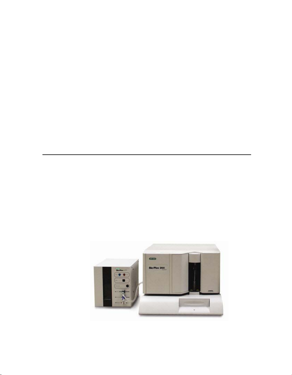
The Bio-Plex suspension array system consists of a fully integrated array
reader and microplate platform, with an optional HTF (high-throughput
fluidics) sheath delivery module.
Figure 1. Bio-Plex array reader and microplate platform, with optional HTF
1
Page 14

Bio-Plex Manager Software 6.1 User Guide | Components
The system also includes validation and calibration reagents, a selection of
cytokine and phosphoprotein assays, sample preparation reagents, and a
computer running Bio-Plex Manager
phase, diabetes, cancer and isotyping assays have been introduced with this
version of the software.
Check www.bio-rad.com/bio-plex/x-plex for newly-available assays and
reagents.
The assays contain sets of microscopic color-coded beads, each of which is
conjugated with a different reactant.
Reactants can include:
•DNA
• Enzyme substrates
• Receptors
•Antigens
• Antibodies
These can be used to create, for example, a capture sandwich immunoassay.
To perform a multiplex reading, samples are mixed with conjugated
microsphere and reactant mixtures; next, fluorescent reporter molecules are
added. The assays are loaded into the wells of a 96-well microtiter plate, and
the plate is inserted into the microplate platform. The platform and array
reader are controlled by a computer running Bio-Plex Manager software.
The detection system in the array reader uses two lasers to analyze the
microspheres in a flow stream. The first laser identifies each microsphere and
its associated analyte based on the fluorescent signature of the microsphere,
and the second measures the amount of analyte, using the reporter molecules
attached to the analytes. When the reading is complete, Bio-Plex Manager
displays the raw data and generates detailed summary reports.
™
6.1 software. New angiogenesis, acute
Components
A certified Bio-Rad service engineer will install the complete Bio-Plex
suspension array system at your site, including the array reader, microplate
platform, and computer. The system setup procedure is described in
“Bio-Plex 200 System Hardware Instruction Manual”, available for download
from the Bio-Rad website.
The Bio-Plex suspension array system includes the following components:
• Array reader
• Microplate platform
• Bio-Plex MCV Plate IV (required for Bio-Plex Manager 5.0 and later)
2
Page 15

Advantages
•Bio-Plex reservoir
• Pentium-class PC, preinstalled with operating system, Microsoft
Excel, Microsoft Internet Explorer, Microsoft.NET, and Bio-Plex
Manager Instrument Control software
• Software package containing Bio-Plex Manager CD-ROM and a
hardware protection key
• Instrument manual for array reader and microplate platform
• Sheath fluid bottle
• Sample needles (two long)
• Protective shield
• Waste bottle
• Communications cable to connect the reader to the computer
• Communications cable from microplate platform to the computer
• Computer monitor
• Power cords
• Computer keyboard
• Computer mouse
• HTF (High Throughput Fluidics), if selected
• Communications cable from the reader to the HTF, if HTF is present
The Bio-Plex suspension array system comes with these reagents:
• Bio-Plex Calibration Kit (CAL1 and CAL2)
• Bio-Plex Validation Kit 4.0 (optics, fluidics, reporter, and classify
components)
• Sheath fluid
Advantages
With the Bio-Plex suspension array system, you can:
• Simultaneously quantitate up to 100 different analytes from culture
media and serum samples as small as 50 μl
• Automatically analyze all the samples in a 96-well microtiter plate—
yielding up to 9,600 data points—in about 30 minutes
• Instantly customize your experiments by mixing Bio-Plex assays or
creating your own assays
• Analyze results, prepare reports, and print and/or export data
immediately after each reading
• Provide a complete electronic audit trail of data generation and
analysis in a secure digital environment with multilevel account
access, that is compliant with the Code of Federal Regulations,
Title 21, Part 11, “Electronic Records; Electronic Signatures”
3
Page 16

Bio-Plex Manager Software 6.1 User Guide | For More Information
For More Information
For more on the principles and concepts of the Bio-Plex suspension array
system, see Basic Concepts in the Appendix on page 227.
Bio-Rad Technical Support
Bio-Rad Technical Support in the United States is open Monday through
Friday, 5:00 a.m. to 5:00 p.m., Pacific Time. Worldwide technical support is
available on the Web at www.consult.bio-rad.com.
Phone: (800) 424-6723, option 2
Fax: (510) 741-5802
E-mail:LSG.TechServ.US@Bio-Rad.com (U.S.)
LSG.TechServ.Intl@Bio-Rad.com (International)
Web: http://www.consult.bio-rad.com
4
Page 17

Bio-Plex Manager Software 6.1 User Guide
2 Bio-Plex Manager™
Software Overview
Bio-Plex Manager™ 6.1 software runs on a computer installed with the
Windows XP or Windows 7 operating system, and requires a hardware
protection key, also known as a HASP key, installed on either the computer
itself or the computer network system. The software features a standard
Windows interface, with pulldown menus, toolbars, and keyboard shortcuts.
Bio-Plex Manager comes in two editions—Standard Edition and Security
Edition—and with three available licenses: Instrument Control, Desktop, and
Network, described below. The computer included with the Bio-Plex
suspension array system comes preinstalled with a compatible operating
system and a Bio-Plex Manager Standard Edition, Instrument Control license.
Software Editions
Bio-Plex Manager software comes in two editions:
• Standard Edition gives all users equal access to all features of the
software with no restrictions and no electronic audit trail
• Security Edition provides different levels of user access to various
features and creates a complete electronic audit trail of all data
generation and analysis. The Security Edition can be run in Secure
Mode, with all the security features enabled, or Standard Mode,
which behaves like the Standard Edition of the software
5
Page 18

Bio-Plex Manager Software 6.1 User Guide | Software Licenses
NOTE: Bio-Plex Manager Security Edition must be installed on the Windows
XP Professional or Windows 7 operating system for full security and
functionality.
Software Licenses
Bio-Plex Manager software is available with three different licenses:
• Instrument Control (previously called Workstation) license enables
the software to control the array reader and microplate platform
and to collect, analyze, and output data
• Desktop license enables the software to analyze data files but not
control the array reader and platform. The instrument
communication and control functions are not available with this
license
• Network license provides Desktop licenses to multiple users over
a computer network. The Desktop license enables the software to
analyze data files but not control the array reader and platform
This user guide assumes that you are using the Standard Edition with an
Instrument Control license, unless otherwise noted. The Security Edition user
levels and restrictions are described in detail in the Appendix on page 219.
Compatibility with Luminex Software
Bio-Plex Manager 6.1 is compatible with Luminex xPONENT software.
Because the Luminex LXR library has been updated, older Luminex IS 2.3
software will not function once you upgrade to Bio-Plex Manager 6.1. You
must upgrade your Luminex IS 2.3 software to the current version in order to
run both applications on the same machine.
If you install Bio-Plex Manager 5.0 or later on a computer with Luminex
xPONENT software, note the following:
• To avoid communication conflicts with the array reader and
platform, do not run Bio-Plex Manager and Luminex software at
the same time.
• If you switch between the two software applications, you must
recalibrate the array reader before acquiring data.
6
Page 19
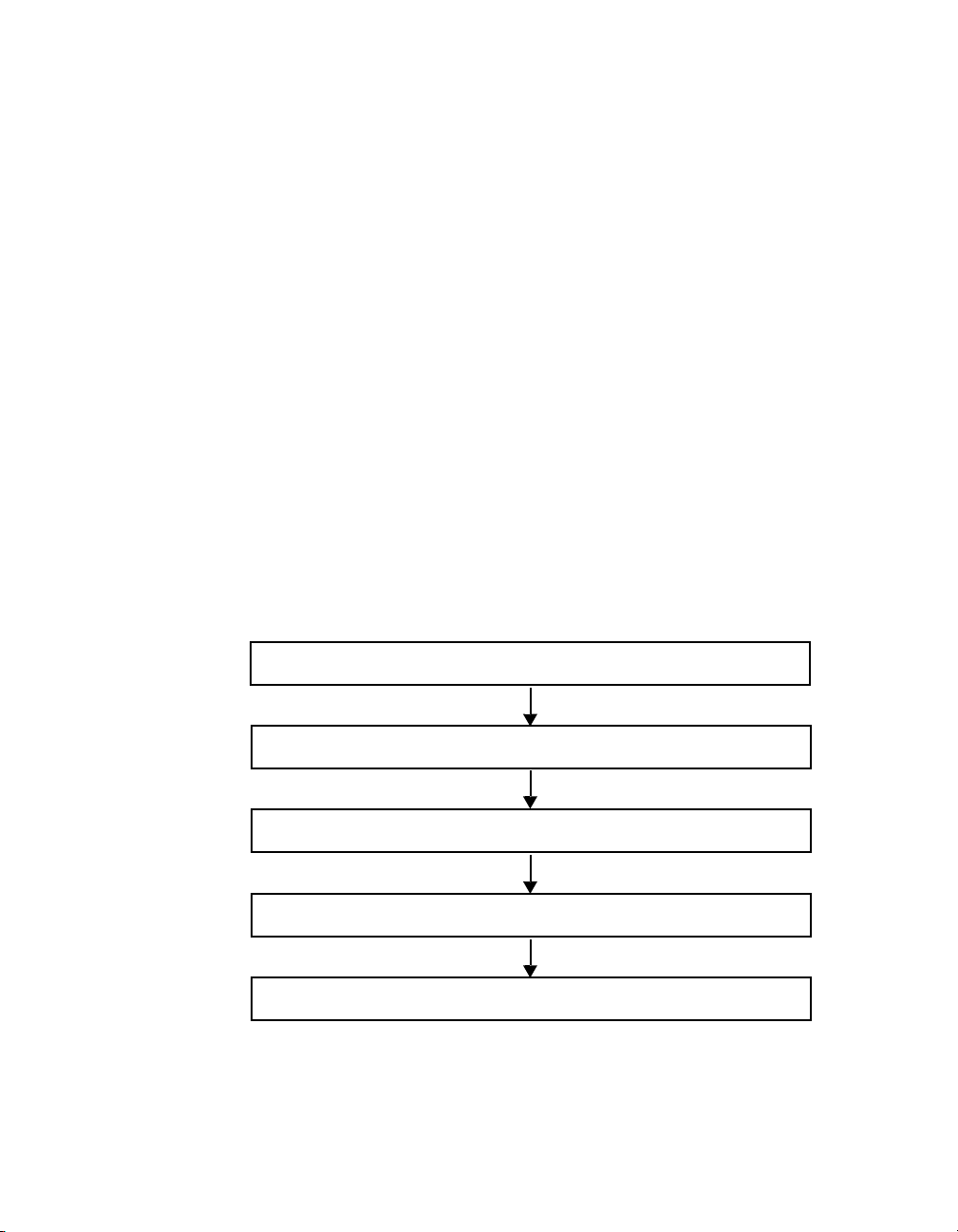
ANALYZING LUMINEX DATA IN BIO-PLEX MANAGER
Start up and calibrate array reader
Create a protocol by specifying analytes, plate, and standards
Run the protocol
Review results and generate reports
Print and/or export the data
Bio-Plex Results Generator 3.0 converts CSV Output files from xPONENT 3.1
and 4.0 into Bio-Plex Manager data files. You can analyze the converted
results on any computer running Bio-Plex Manager 4.0 or later. You can make
the files available to an entire workgroup by placing them on a public server.
With earlier versions of Bio-Plex Manager, you had to separately install
Bio-Plex Results Generator. Beginning with Bio-Plex Manager 6.1, Bio-Plex
Results Generator is automatically included in the Bio-Plex Manager
installation.
The Bio-Plex Results Generator 3.0 application (RBXGenerator_3.exe) is
included as a separate product on the Bio-Plex Manager 6.1 software CD.
This allows you to install it on a machine that does not have a Bio-Plex
Manager installation. There is also a help file (Bio-Plex Results Generator 3.0
Online Help) to walk you through installing the Results Generator and setting
up Luminex protocols for conversion.
General Workflow
To collect, analyze, and output data using Bio-Plex Manager software, follow
the general steps outlined below.
.
General Workflow
Figure 2. Bio-Plex Manager software workflow
7
Page 20
Bio-Plex Manager Software 6.1 User Guide | General Workflow
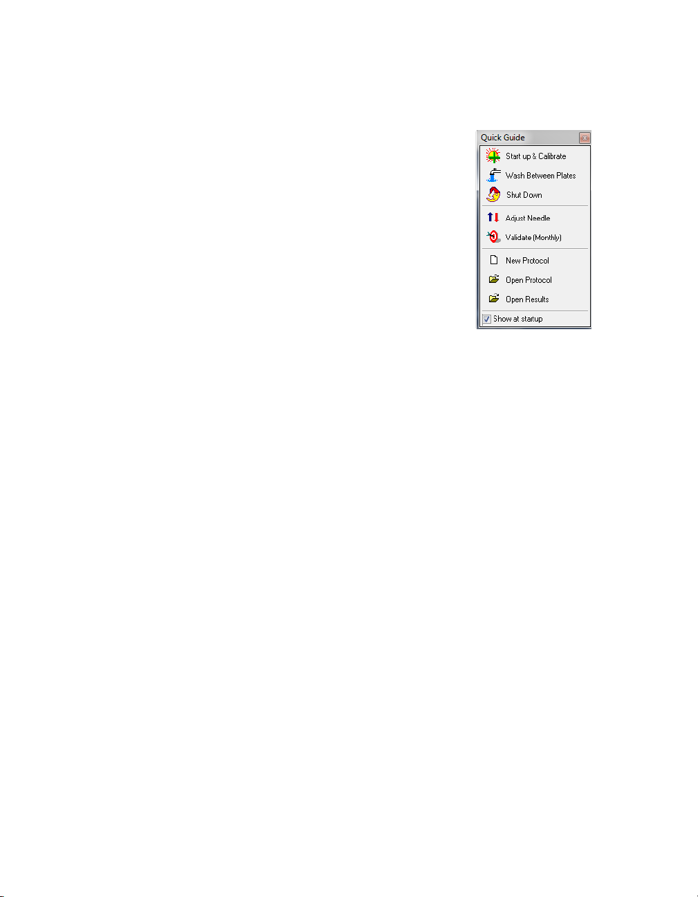
Quick Guide
The Quick Guide, which displays automatically at
startup, is designed to guide you through the typical
Bio-Plex Manager workflow, from startup and
calibration through shut down.
Commands, such as Start up & Calibrate, open dialog
boxes that contain choices to guide you through the
procedures.
Figure 3. Quick Guide
8
Page 21

Types of Files
There are two main types of files created and used by Bio-Plex Manager:
• Protocol files (see page 53) contain the settings and controls for
reading a microplate
• Results files (see page 143) contain the data from each reading,
and tools and reports for analyzing that data
The application database file (bioplexdata.mdb) is installed on your hard drive
or file server when you install the software. This database contains calibration,
validation, and instrument operation information. See page 13 for more detail.
Key Software Features
Bio-Plex Manager 6.1 is a single integrated software package that has:
Comprehensive instrument functions
• Data collection
• Maintenance
• Validation
• Automatic error detection and logging
Comprehensive data display
• Raw data presentation including tables, bead maps and histograms
• Customizable tabular presentations
• Customizable standard curve and bar graph displays
Comprehensive Calculations
• Data normalization (internal controls for gene expression analysis)
• Auto calculation and display of usable assay range
• Multiple standard curve fitting options, including Brendan
Scientific, StatLIA, Logistic 5PL.
Comprehensive and versatile automated export options
• Excel (now including optional standard curve graphs)
• Comprehensive .xml file
• New Luminex CSV (comma-separated values) output
• New customizable reports through style sheets
• New custom report for export to custom macros
CFR 21 Part 11 compliance
• User access management
• Comprehensive audit trail and instrument logs
• Secure documents (results files and protocols)
Types of Files
9
Page 22

Bio-Plex Manager Software 6.1 User Guide | Key Software Features
10
Page 23

Bio-Plex Manager Software 6.1 User Guide
3 Software Installation
Install, or reinstall, Bio-Plex Manager™ 6.1 software as described in the
following section. If you need to upgrade your software from a previous
version, see the “Bio-Plex Manager 6.1 Software Upgrade and Configuration
Guide” to determine the part number of your upgrade kit.
System Requirements
Component Minimum Recommended
Operating system Windows XP (XP Professional required
for running Security Edition) or
Windows 7 (32-bit)
Processor Pentium 4 or equivalent, 2.8 GHz Core 2, 2.6 GHz or higher
Hard disk space 80 GB 160 GB
System memory 1 GB 2 GB
Screen resolution 1024 x 768 (Windows XP)
1280 x 1024 (Windows 7)
Screen colors 256 colors 24-bit True Color
Ports for connecting
instrument (required for
Instrument Control
license only)
Port for connecting
the HASP key
Other software Internet Explorer 6.0 or later
NOTE: For Windows 7, the Instrument Control version of Bio-Plex Manager 6.1 can be run only on
32-bit; it is not compatible with 64-bit.
1 RS232 serial port and
1 USB port
1 USB port 1 USB 2.0 port
Microsoft Excel 2003 or later
Windows XP Professional
1280 × 1024
1 RS232 serial port and 1 USB 2.0
port
Internet Explorer 8.0
Microsoft Excel 2007
11
Page 24
Bio-Plex Manager Software 6.1 User Guide | Software Installation
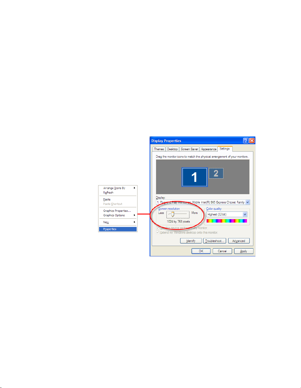
Required Screen Resolution
Your computer screen resolution must be set to at least 1024 x 768 pixels for
correct display of the Bio-Plex Manager interface. The status bar and some
dialog boxes will not display properly at lower resolutions. If your display is
currently set to a lower resolution:
1. Go to the Windows Start menu, select Settings, and select Control
Panel.
2. Open the Display control panel.
3. In the Display Properties dialog, select the Settings tab (see Figure 3).
4. Drag the Screen Area slider to the right (toward More) until you have
selected 1024 x 768 pixels. Click OK to accept the settings.
12
Figure 4. Changing the screen resolution settings
Page 25

Installing the Software
To install or reinstall the software, insert the Bio-Plex Manager CD into the
CD-ROM drive on your computer.
NOTES
• Before installing Bio-Plex Manager 6.1, we recommend that you
first uninstall any existing version of Bio-Plex Manager on your
computer
• We recommend that you turn off any antivirus protection software
before installation. Such software, if active, can greatly slow the
progress of the installation. If you are unable to turn off your
antivirus protection software, allow 15 minutes for complete
installation. Do not cancel the installation during this period
The Bio-Plex Manager Installation Program opens, displaying a navigation
screen for performing the installation.
Microsoft.NET
Microsoft.NET is automatically installed on your computer when you install
Bio-Plex Manager. It is required to support the logistic curve-fitting features of
Bio-Plex Manager.
Installing the Software
Bioplexdata.mdb File
During installation, you will be prompted to save the application database file
(bioplexdata.mdb) to a location on your hard drive or a file server. This
database file contains logs of calibration, validation, and instrument
operations activity for your instrument.
• For more information about the Calibration Log, see page 34
• For more information about the Validation Log, see page 45
• For more information about the Instrument Operations Log, see
page 51
You can save the bioplexdata.mdb file to any folder on your computer. The
default location is the Bio-Plex Manager application folder. If your computer is
connected to multiple instruments, each instrument must have a separate
bioplexdata.mdb file saved in a different folder.
For more information about the calibration, validation, and instrument
operations logs in Bio-Plex Manager 6.1 Security Edition, see Controlling the
System on page 25.
13
Page 26

Bio-Plex Manager Software 6.1 User Guide | Software Installation
NOTE: The bioplexdata.mdb file is not compatible with versions of Bio-Plex
Manager earlier than 4.0. If you have an earlier version of the software,
installing 4.0 or later will copy the data from your existing database file
(bioplex.mdb) into the new database. A copy of your old database will remain
in the application folder.
Luminex LXR Directory and Files
A directory called Luminex is automatically created in the Program Files folder
on your computer during installation. Inside this folder is a folder called LXR
that contains various applications for monitoring and communicating with the
array reader and platform. A Windows service called LXService is also
installed and started. This service enables automatic communication with the
instrument when you open Bio-Plex Manager.
Hardware Protection Key (HASP Key)
A hardware protection key, also known as a HASP key, is required to run
Bio-Plex Manager. The HASP key determines the license (Instrument Control,
Desktop, or Network) and the edition (Standard or Security) of your Bio-Plex
Manager. A complete list of HASP key part numbers and the software versions
they enable is in the Bio-Plex Manager 6.1 Software Upgrade and
Configuration Guide.
Instrument Control or Desktop HASP keys must be attached to a USB port on
the computer running the software. Network HASP keys must be attached to
a USB port on the network file server computer.
The HASP key has a driver that is automatically installed when you install BioPlex Manager.
Uninstalling
To uninstall Bio-Plex Manager from your computer, use the Windows Add/
Remove Programs function. Click the Windows Start button, select Settings,
select Control Panel, double-click Add/Remove Programs, and follow the
instructions for removing the program.
14
Page 27

Bio-Plex Manager Software 6.1 User Guide
4 Starting the System
Before starting Bio-Plex Manager™ 6.1 software, make sure the Hardware
Protection Key is attached to your computer, and switch on the array reader,
the HTF (if one is being used), and the microplate platform. This turns on the
optics inside the array reader and enables communication between the array
reader and software.
NOTE: Avoid using other applications while Bio-Plex Manager is
communicating with the array reader. Running other applications may
interrupt communication between Bio-Plex Manager and the array reader.
Starting Bio-Plex Manager
To start Bio-Plex Manager, click the application icon on your desktop
or select Bio-Plex Manager 6.1 from the Programs directory on your Windows
Start menu. The software opens and attempts to connect to the array reader
and platform.
15
Page 28
Bio-Plex Manager Software 6.1 User Guide | Starting Bio-Plex Manager
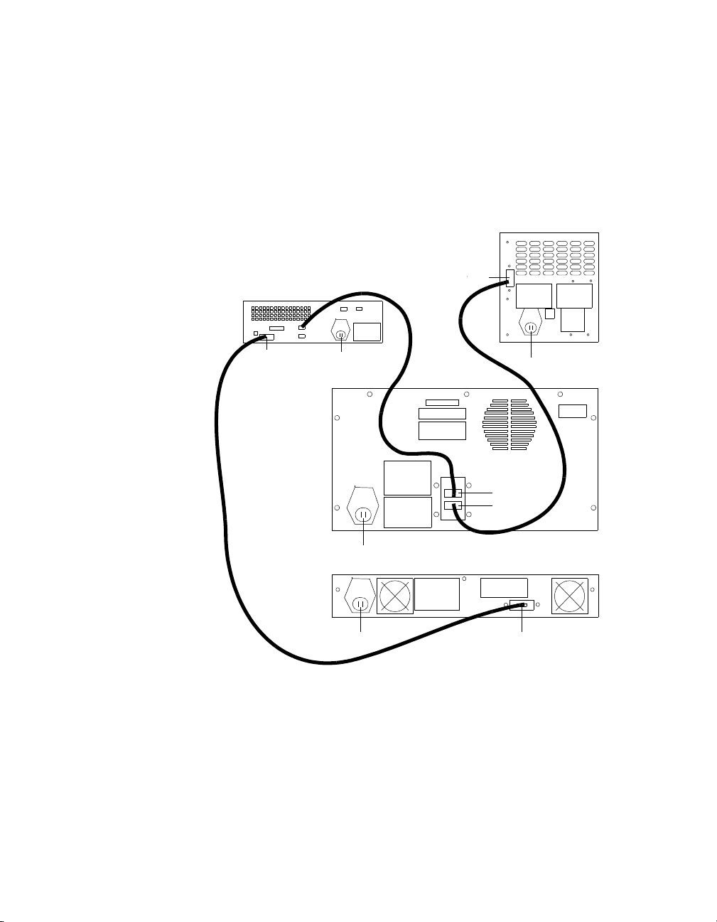
Microplate Platform
Power
Serial port
Array Reader
Power
P1
P2
HTF
Computer
Serial
port
Power
Serial port Power
USB1
USB2
Connecting with the Array Reader and Microplate Platform
The computer running Bio-Plex Manager software is connected to the array
reader by a USB cable, and to the microplate platform by a serial cable. See
the figure below for a diagram of the cable connections.
16
Figure 5. System cable connections
Page 29
Starting Bio-Plex Manager
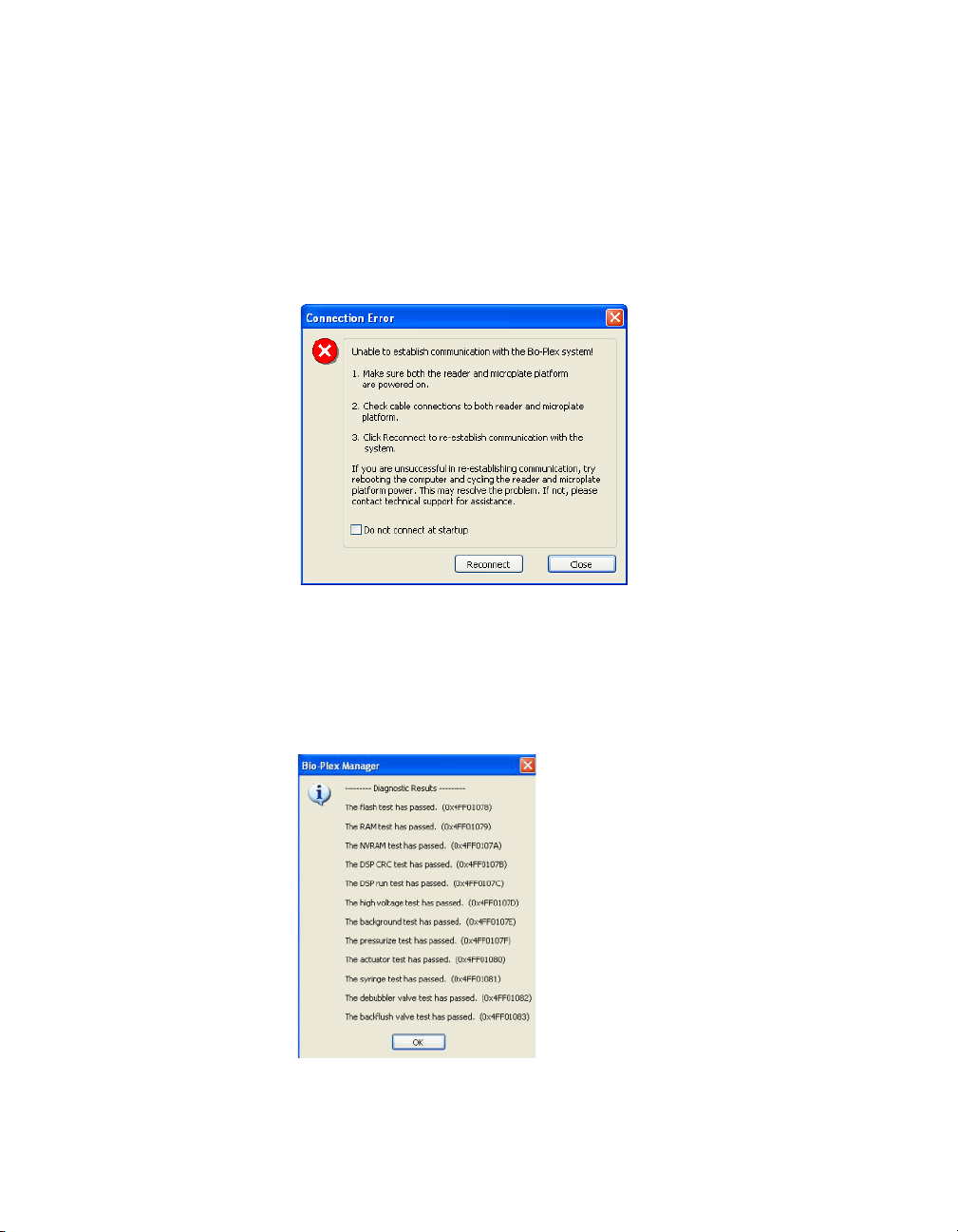
Communication between the Array Reader and Microplate Platform
Communication between the computer and the array reader and microplate
platform is automatically established when you open Bio-Plex Manager. If
Bio-Plex Manager is unable to communicate with the instrument, a dialog box
prompts you to check the cable connections.
Figure 6. Connection Error dialog
Make sure the instrument is turned on, check the cable connections, and then
click Reconnect in the dialog. If you are still unable to connect, try restarting
the computer, array reader, and platform. You can also choose the Run
Diagnostic option found under the Instrument menu. This produces a report
which can help Bio-Rad Technical Support determine the cause of the
problem.
Figure 7. Run Diagnostics Report
17
Page 30

Bio-Plex Manager Software 6.1 User Guide | Starting Bio-Plex Manager
If you do not want to automatically connect to the array reader and platform
when you open the software, select the Do not connect at startup checkbox.
This is useful if you are not connected to an instrument or want to use the
software without connecting to the instrument. To re-enable automatic
connection at startup, select Reconnect from the Instrument menu (see next
section).
Disconnecting and Reconnecting
Communication between the computer and the array reader and platform is
closed when you exit Bio-Plex Manager. If you need to disconnect from the
array reader and platform without shutting down Bio-Plex Manager software
(for example, to troubleshoot the instrument), go to the Instrument menu and
select Disconnect.
To reconnect to the array reader and platform while Bio-Plex Manager is
running, select Reconnect from the Instrument menu. This dialog also enables
automatic connection each time you start the software, if it has been disabled
(see previous section).
18
Page 31

Disconnecting with Sleep Mode
When your computer goes into sleep mode, the instrument is disconnected
from Bio-Plex Manager. When you awaken your computer from sleep mode,
you will not be able to reestablish the connection to the instrument using the
Reconnect option on the Instrument menu, and you will need to restart BioPlex Manager.
Bio-Plex Manager overrides any sleep mode settings on your computer.
Therefore, as long as it is running, your computer will not go into sleep mode.
However, Bio-Plex Manager does not prevent you from actively putting your
computer into sleep mode. It is recommended that you do not do this as long
as Bio-Plex Manager is running.
Menu and Toolbars
Bio-Plex Manager includes a menu bar and main toolbar at the top of the
application window.
The pulldown menus contain all the major functions of the software. Note that
these menus change depending on whether you are displaying a Protocol
window, a Results window, or neither.
You can move quickly between any number of open Bio-Plex Manager
windows. Hold down the Ctrl key, then press Tab.
The main toolbar includes the major instrument controls, including Start up &
Calibrate, Shut Down, Wash, Unclog, etc. The various Protocol and Results
windows also contain their own toolbars, with commands specific to those
windows. These are described in greater detail in the following chapters.
Menu and Toolbars
Status Bar
The Instrument Status Bar shows the current state of the instrument
(Calibration, Warm Up, Ready, Pressurizing, etc.). It includes a Cancel button
for canceling the current operation (see page 51).
Figure 8. Instrument status bar
When the array reader performs an operation, the time remaining for the
operation shows in the instrument status bar.
19
Page 32

Bio-Plex Manager Software 6.1 User Guide | Quick Guide
The Bio-Plex Manager software status bar is below the instrument status bar,
and provides information about the command under the cursor. This
information is continuously updated as you move your cursor over the
software window.
The software status bar also shows the current user and, if you are using the
Security Edition of the software, whether you are in Secure Mode (shown as a
"locked" symbol ) or Standard Mode (shown as "unlocked" ). See
page 5 of this manual, and the Bio-Plex Manager 6.1 Software Upgrade and
Configuration Guide for more information about the Security Edition.
The software status bar also shows the Caps Lock, Scroll Lock, and Num
Lock keyboard status.
Quick Guide
When Bio-Plex Manager first opens, a Quick Guide toolbar appears in the
upper right corner of the screen. You can use the Quick Guide to guide you
through the typical workflow, from start up and calibration through shut down.
20
Figure 9. Bio-Plex Quick Guide
By default, the Quick Guide opens automatically when you start Bio-Plex
Manager. To disable, deselect the Show at startup checkbox at the bottom of
the guide.
To open the Quick Guide after closing, select Quick Guide from the View
menu.
Page 33

Sample Needle Adjustment
See the Bio-Plex 200 System Hardware Instruction Manual or the Luminex
manual for instructions on installing the sample needle.
WARNING: To protect hands and fingers, keep them out of the microplate
platform when the needle is not in the down position.
The height of the sample needle must be adjusted when the microplate type
has changed, and/or when the sample needle is replaced. The MCV plate
included with your system provides a method for adjusting sample needle
height for standard flat-bottom plates (catalog #171-025001), filter plates
(Millipore catalog #MSBVS1210), or PCR plates.
Follow these steps to adjust the sample needle height.
1. Turn on the array reader and microplate platform.
2. Launch the Bio-Plex Manager software.
3. Click Instrument in the menu bar and choose Adjust Needle. The
following dialog box appears.
Sample Needle Adjustment
Figure 10. Adjust Needle dialog
4. Click Eject/Retract to eject the plate holder.
5. Place the MCV plate on the microplate platform with the black arrow
facing toward the array reader.
6. Click on the Eject/Retract button to retract the plate.
7. Tape the access door of the microplate platform open. It will be
necessary to be able to see inside the access door.
21
Page 34

Bio-Plex Manager Software 6.1 User Guide | Sample Needle Adjustment
Needle height
adjustment
thumbscrew
8. Select the plate type to adjust the needle height appropriately. Choose
Standard Plate if you are using a Bio-Plex Pro™ flat-bottom microplate
for magnetic beads or the Millipore filter plate. Your other choice is PCR
Plate.
9. In the Adjust Needle window, click on the Up/Down button. The needle
will move to the down position.
10. With the needle in the down position, loosen the needle height
adjustment thumbscrew at the top of the needle so that the needle
housing can move up and down freely.
NOTE: All adjustments to the needle height must be made when the needle is
in the down position.
Figure 11. Sample needle assembly
22
11. By holding onto the needle height adjustment thumbscrew on the
needle arm, manually move the needle so that it just touches the
bottom of the needle adjustment well of the MCV plate. Move the
needle up and down gently a couple of times to verify that the needle is
barely touching the bottom of the well.
12. Tighten the needle height adjustment thumbscrew so that it is no longer
possible to manually move the needle up and down. Take care to
ensure that the needle does not move while you are tightening the
screw. Do not overtighten.
13. In the Adjust Needle window, click on the Up/Down button to move the
needle up and down. Look inside the microplate platform at the MCV
plate. The needle should just touch the MCV plate at the bottom of the
cutout (use flashlight for better viewing). Readjust the needle height if
necessary.
14. Save these settings. This allows Bio-Plex Manager to warn you which
type of plate the system will use, before it starts a run.
15. When the needle is adjusted properly, click the Eject button.
16. Remove the MCV plate from the microplate platform.
Page 35

Sample Needle Adjustment
17. Perform a Wash Between Plates step to remove any air introduced into
the lines.
23
Page 36

Bio-Plex Manager Software 6.1 User Guide | Sample Needle Adjustment
24
Page 37

Bio-Plex Manager Software 6.1 User Guide
5 Controlling the System
This chapter covers the Bio-Plex Manager™ 6.1 software commands that
control basic system functions, such as instrument start up, warm up,
calibration, validation, and shut down.
NOTE: The startup, warm up, and calibration functions must be performed
prior to running an assay with Bio-Plex Manager, all of which together take
about 45 minutes. The Start up & Calibrate function allows you to complete
these steps with one command.
WARNINGS:
• The sheath fluid container and the waste fluid container should be
closely monitored
• The sheath fluid bottle must be placed at the same level as the
array reader, unless you are using the Bio-Plex High-Throughput
Fluidics (HTF) or Luminex Sheath Delivery System (SDS). The fluid
level should be below the air inlet connection and above the sheath
outlet connection. Always check the sheath fluid level before
starting a run or procedure
• If you are using the Bio-Plex HTF or Luminex SDS, it should sit on
the counter next to the array reader, while the sheath fluid cube
should be placed 3-4 feet below the array reader (for example, on
the floor)
• The waste fluid container receives waste from the system. Do not
allow the waste container to overflow. Empty the waste bottle each
time the sheath fluid bottle is filled. The waste container should be
placed on the bench next to the instrument. Never place this
container on top of the instrument. All waste containers should
have vented caps
25
Page 38

Bio-Plex Manager Software 6.1 User Guide | Controlling the System
Wells highlighted
in yellow
Bio-Plex MCV Plate IV
Bio-Plex Manager 5.0 and later requires the use of the Bio-Plex MCV
(Maintenance, Calibration and Validation) Plate IV. This plate contains wells
marked for the different types of fluids used in validation, washing, calibration,
and other functions. The Bio-Plex MCV Plate IV has been modified from the
previous MCV plate to work with Bio-Plex Validation Kit 4.0 and its Reporter
and Classify bead sets. It also includes two open needle wells for adjusting
needle heights for microplates or PCR plates.
NOTE: Bio-Plex Manager 5.0 and later require the use of the Bio-Plex MCV
Plate IV, the Bio-Plex Validation Kit 4.0, and the Bio-Plex Calibration Kit.
26
Figure 12. Bio-Plex MCV Plate IV
When a particular procedure such as calibration requires you to add solutions
to the Bio-Plex MCV Plate IV, the dialog box describing the procedure
includes a diagram of the MCV Plate IV with the wells to be loaded highlighted
in blinking yellow.
Figure 13. Highlighted wells in diagram indicate wells to be filled
Page 39

Start Up
Startup is a series of fluidic functions that prepares the array reader to acquire
data. This process requires the Bio-Plex MCV Plate IV, distilled water, and
70% isopropanol. Startup takes approximately 10 minutes.
NOTE: The startup procedure can be performed while the optics are warming
up, but no validations, calibrations or runs should be performed before the
optics are warmed up. This takes an estimated time of 30 minutes.
Click the Start Up button on the main toolbar or select the command
from the Instrument menu. Follow the step-by-step directions in the dialog
box for preparing the MCV Plate IV.
Start Up
Figure 14. Start Up dialog
Insert the prepared plate into the microplate platform and click OK to begin
the startup process.
27
Page 40

Bio-Plex Manager Software 6.1 User Guide | Controlling the System
Optics Warm Up and Shut Down
To ensure accurate and reproducible results, the optics (that is, the lasers) in
the array reader must warm up for at least 30 minutes prior to calibration,
validation, and reading assays. Optics warm up begins when you first turn on
the array reader.
You can proceed with the array reader startup procedure described in the
previous section while the optics are still warming up. However, if you try to
perform calibration, validation, or an assay reading, you will receive a warning
message.
You can cancel the warm up procedure using the Cancel Operation command
on the Instrument menu or the Cancel button in the status bar; however, this is
not recommended. Results for identical readings may vary if the optics have
not reached optimal operating temperature.
NOTE: If you attempt to start a reading during warm up, you can eject the
plate carrier using the Eject/Retract Plate command on the main toolbar
and remove the plate for storage until warm up is complete, without canceling
the warm up procedure.
If the array reader is idle for more than four hours, the optics automatically
power down (though the array reader itself remains on). Depending on the
length of the shutdown, a full 30-minute warm up period may be required
before more readings can be taken.
28
Click the Warm Up button
to begin warm up after automatic power down
menu
If you attempt to perform a reading after automatic power down, you receive a
warning message and the optics begin warming up.
on the main toolbar or from the Instrument
.
Page 41

Calibration
Calibration of the array reader is essential for optimal performance and dayto-day reproducibility of results. Calibration is required:
• Each day after the startup procedure is complete and the optics
have warmed up
• If the array reader temperature changes by more than 2ºC during
the course of the day. (If the temperature changes by more than
2ºC, a message box prompts you to recalibrate)
• Before data acquisition, if you switch between Bio-Plex Manager
and Luminex software installed on the same computer (see page 6)
NOTE: Before calibrating, make sure that optics warm up is complete.
The Bio-Plex Calibration Kit contains calibration microspheres (CAL1 and
CAL2 beads) with stable fluorescent intensities in the RP1, CL1, and CL2
wavelength ranges. The calibration process uses these microspheres to
adjust voltage settings for optimal and consistent microsphere classification
and reporter readings over time and across different instruments. Current
calibrated settings are automatically applied to any new session.
Calibration using Bio-Plex Manager requires the Bio-Plex MCV Plate IV, CAL1
beads and CAL2 beads from the Bio-Plex Calibration Kit, and distilled or
deionized water. The CAL1 beads calibrate the array reader's doublet
discriminator and classification channels, while the CAL2 beads calibrate the
array reader's reporter channel for reporter fluorescence detection.
Calibration
29
Page 42

Bio-Plex Manager Software 6.1 User Guide | Controlling the System
Opening the Calibration Dialog Box
To begin calibration, click the Calibrate button on the main toolbar or
select Calibrate from the Instrument menu. The Calibrate dialog box opens.
30
Figure 15. Calibrate dialog
At the top of the dialog box, enter your name in the field. If you are using the
Security Edition of the software in Secure Mode, your user name will be listed
and grayed out.
The time and date of the last calibration using Bio-Plex Manager are listed, as
is the temperature at the time of that calibration. If the temperature has not
changed by more than 2ºC in a single day, it is not necessary to recalibrate the
instrument.
Next, select the calibration type by clicking on the CAL1 & CAL2, CAL1 Only,
or CAL2 Only button. You should perform both CAL1 and CAL2 calibration
daily.
Selecting/Entering Calibration Control Numbers
Under Select Control Numbers in the Calibrate dialog box, you can either
select existing control numbers for your CAL1 and CAL2 microspheres, or
enter new control numbers.
Page 43

Calibration
Select existing control numbers from the pulldown list, and the target values
for the control numbers appear in the appropriate fields.
When you receive a new Bio-Plex Calibration Kit, you must add the new CAL1
and CAL2 control numbers and target values to the Calibrate dialog. These
numbers are printed on the bottles containing the beads.
NOTE: It is critical that you enter the correct target values for your CAL1 and
CAL2 calibrators. Entering incorrect values results in an incorrectly calibrated
array reader, which adversely impacts assay results.
To add a new CAL1 control number, click the Add button under CAL1 Control
Number in the Calibrate dialog. The Add New CAL1 Control Number dialog
box opens.
Figure 16. Adding a new CAL1 control number
In the dialog, enter the control number from the CAL1 bottle in the Enter
Control Number field. If the expiration date is printed on the bottle, select the
option button next to the date field under Expiration Date and click the
pulldown button next to the field to open the calendar selection box.
Figure 17. Calendar selection box
Scroll through the calendar using the scroll buttons at the top. Click to select a
particular date. Use the up/down arrow keys to highlight and change
individual date components.
31
Page 44

Bio-Plex Manager Software 6.1 User Guide | Controlling the System
Next, enter the DD, CL1, and CL2 target values for the control number, as
printed on the bottle, in the appropriate fields.
NOTE: Use only the DD target value on the Bio-Plex CAL1 bottle. Using
Bio-Rad’s calibrators is highly recommended, because other manufacturers’
DD target values have not been validated.
Click Add to close the dialog box and save your changes.
To add a new CAL2 control number, click the Add button under CAL2 Control
Number in the Calibrate dialog box. The Add New CAL2 Control Number
dialog box opens.
32
Figure 18. Adding a new CAL2 control number
In the dialog, enter the control number from the CAL2 bottle in the field. Select
the expiration date, if printed on the bottle, as described above. Next, enter
the Low RP1 target value for the control number, as printed on the bottle, in
the RP1 field.
NOTE: The CAL2 calibration bottle label lists two RP1 (also known as PMT, for
photomultiplier tube) target values: Low RP1 and High RP1. The High RP1
target value cannot be used in Bio-Plex Manager 5.0 or higher. All calibration
is done at the Low RP1 target value, which must fall between 3000 and 4000.
The High RP1 target value remains on the bottle label because it can be used
with earlier versions of Bio-Plex Manager. Assays that require calibration using
the High RP1 target value can be run by selecting the checkbox labeled “Run
at High RP1 Target” in the Run Protocol window.
When you are done, click Add to close the dialog box and save your changes.
Your new control numbers are added to the selection lists in the main
Calibrate dialog.
To delete a particular control number, first select it in the Calibrate dialog box,
and then click the Delete button.
Page 45

Calibration
Setting Up the Calibration
When you have specified the control numbers of your calibration
microspheres and specified the type of calibration you want to perform (CAL1
& CAL2, CAL1 Only, or CAL2 Only), click OK in the Calibrate dialog.
Another dialog box lists step-by-step instructions for preparing the Bio-Plex
MCV Plate IV.
Figure 19. Preparing the Bio-Plex MCV Plate IV for CAL1 & CAL2 calibration
NOTES: When preparing the MCV Plate IV, do the following:
• Important: Before vortexing, remove the calibration beads from 2 to
8°C (36 to 46°F) storage, and allow them to warm to room
temperature. Vortex each bottle for 30 seconds. Proper suspension
of the microspheres is essential for efficient calibration
• Never dilute the calibration beads, and be careful to limit their
exposure to light. Store at 2 to 8°C immediately following
calibration
• Load 6 drops of beads (approximately 200 μl) per reservoir (CAL1
or CAL2)
•The DI H
deionized water
O well of the MCV Plate IV holds about 3 ml of distilled or
2
33
Page 46

Bio-Plex Manager Software 6.1 User Guide | Controlling the System
Number of beads per second should be 100 or higher
Performing the Calibration
Click the Eject/Retract Plate button to eject the microplate platform plate
carrier. Place the MCV Plate IV in the carrier with the arrow facing toward the
platform, and then retract the plate. Click OK to start the calibration process.
As calibration proceeds, the status bar at the bottom of the Bio-Plex Manager
window monitors the progress of calibration. The number of beads per
second should be 100 or higher. Fewer beads per second may indicate a
problem with the fluidics system.
Figure 20. Status bar during calibration
Because calibration beads are highly concentrated, calibration is followed by
three wash cycles using distilled water.
An alert box notifies you whether calibration has succeeded or failed. You also
receive an alert which informs you how many days have elapsed since you
last ran a validation procedure.
If the calibration process failed, check the MCV Plate IV to verify that the
correct beads were added to the wells. Then perform a fluidics wash and
repeat the above steps. For more information, consult the Troubleshooting
chapter.
Logging the Calibration
The Calibration Log provides a list of past calibration dates and times, results,
instrument settings, and other data obtained by Bio-Plex Manager. These data
are stored in a log file called bioplexdata.mdb. By default, the file is saved in
the main Bio-Plex Manager application folder on your computer.
NOTE:
This database is not compatible with versions of Bio-Plex Manager earlier
than 4.0. If you have an earlier version of Bio-Plex Manager, installing version 4.0
or later copies data from your existing database (bioplex.mdb) into the new
database. A copy of the old database remains in the application folder.
34
Page 47

Calibration
To open the Calibration Log, go to the View menu and select Calibration Log.
The Calibration Log viewer opens.
Figure 21. Calibration Log viewer
Each calibration is listed by date and time. If you are using Bio-Plex Manager
Security Edition in Secure Mode, the User and Access Level columns list
information about the user who was logged into the application when each
calibration was performed. The Result column notes the result of each
calibration, including whether it passed or failed.
NOTE: If you see a drastic change in a detector's voltage from one calibration
to the next, it could indicate a problem with the instrument. A steadily
increasing detector voltage may indicate that the laser is decreasing in
intensity.
On the toolbar, click Calibration Detail to display additional information
for each calibration, including bead count, system temperature and pressure,
and the reader software and firmware versions. Click Calibration Log to
return to the default view.
For CAL1-only calibrations, the RP1 column displays an entry of NA (not
applicable). For CAL2-only calibrations, the DD, CL1, and CL2 columns
display entries of NA.
35
Page 48

Bio-Plex Manager Software 6.1 User Guide | Controlling the System
To print the calibration report, select Print from the File menu. Print Preview
displays the report as it will appear in a printout. Print Setup allows you to
select some standard print settings.
36
Page 49

Start Up and Calibrate
Each time you use Bio-Plex Manager, the array reader must go through the
start up, warm up, and calibration procedures. The Start up & Calibrate
command allows you to perform these steps with a single command. Click the
Start up & Calibrate button on the Quick Guide or main toolbar, or select the
command from the Instrument menu.
Refer to the following for more information on the individual functions:
• Start Up on page 27
• Optics Warm Up and Shut Down on page 28
• Calibration on page 29
If you prefer, you may perform each function separately. The individual
functions are available on the main toolbar or from the Instrument menu.
Start Up and Calibrate
37
Page 50

Bio-Plex Manager Software 6.1 User Guide | Controlling the System
Wash Between Plates
You should wash the fluidics lines between each plate reading to prevent
traces of sample or other debris from building up inside the system.
Click the Wash Between Plates button on the Quick Guide or main
toolbar, or select the command from the Instrument menu. A dialog box
guides you through the steps for preparing the MCV Plate IV for a wash
procedure.
Figure 22. Steps for washing between plate readings
Add 70% isopropanol and distilled water to the appropriate reservoirs, insert
the plate in the microplate platform, and click OK. This procedure performs a
series of fluidics operations and takes several minutes. After initial system
pressurization (5 to 20 seconds), the time remaining in the operation displays
in the Bio-Plex Manager status bar.
38
Page 51

Remove Air Bubbles
Microscopic air bubbles in the cuvette may cause a sudden shift in the bead
regions during an assay reading. If the array reader detects such a shift, the
reading stops and you are prompted to perform an alcohol wash to force air
bubbles out of the system.
Click the Remove Bubbles button on the main toolbar or select the
command from the Instrument menu. A dialog box guides you through the
steps for preparing the MCV Plate IV for the procedure.
Figure 23. Steps for removing air bubbles from the fluidics system
Add 70% isopropanol and distilled water to the appropriate reservoirs, insert
the plate in the microplate platform, and click OK. This procedure performs a
series of fluidics operations and takes several minutes. After initial system
pressurization (5 to 20 seconds), the time remaining in the operation displays
in the Bio-Plex Manager status bar.
Remove Air Bubbles
39
Page 52

Bio-Plex Manager Software 6.1 User Guide | Controlling the System
Unclog
If the array reader detects an unusually low bead count during a reading, you
are prompted to perform an Unclog operation to remove possible
obstructions from the fluidics lines.
1. Click the Unclog button on the main toolbar or select the command
from the Instrument menu. An instruction box guides you through
preparation of the MCV Plate IV.
Figure 24. Steps for unclogging the fluidics system
40
2. Add 70% isopropanol solution and distilled water to the appropriate
reservoirs.
3. Add 5 drops of CAL1 beads to the CAL1 reservoir.
4. Insert the plate in the microplate platform, and click OK.
This procedure performs a series of fluidics operations and reads a sample of
CAL1 beads to verify that the fluidics are operating properly. It takes several
minutes. After initial system pressurization (5 to 20 seconds), the time
remaining in the operation displays in the Bio-Plex Manager status bar.
Page 53

Validation
Validation of the array reader is a formal process for documenting that the
instrument is fit for its intended use and that it is kept in a state of
maintenance and calibration.
NOTE: Validation is performed after startup and calibration have been
performed. Validation is dependent on successful calibration for accuracy.
You should perform a validation reading:
•Once a month
• Each time you move the array reader, or
• To diagnose any problems with the array reader that cannot be
solved by other procedures (calibrating, washing, unclogging, etc.)
Validation Kit
Bio-Plex Manager requires the use of Bio-Plex Validation Kit 4.0 to perform
validation. It must be used in conjunction with the Bio-Plex MCV Plate IV.
Each Bio-Plex Validation Kit consists of reagents and procedures to evaluate:
• Optical alignment
• Reporter channel performance
• Efficiency of multiplexing
• Integrity of fluidics
The Bio-Plex Validation Kit validates the operation of all of the primary
components of the array system, and can also be used to discriminate
between assay and instrumentation problems.
Validation
Validation Kit Control Number
Each Bio-Plex Validation Kit has a control number linked to the specifications
for the kit. You must use the mini-CD included in the kit to install the control
number on your computer. After installation, you can select the control
number in Bio-Plex Manager, as described in the following section.
See the Bio-Plex Validation Kit 4.0 Instruction Manual for more information.
41
Page 54

Bio-Plex Manager Software 6.1 User Guide | Controlling the System
Setting Up a Validation Run
To set up a validation reading, click the Validation button on the main
toolbar or select the command from the Instrument menu. The Validation
dialog box opens.
Figure 25. Validation dialog
Enter your user name in the top field. If you are using the Security Edition of
the software in Secure Mode, your user name is listed and grayed out.
42
Control Number Selection
In the Validation dialog box, select the Control Number for your specific BioPlex Validation Kit from the Control Number pulldown list. The expiration date
for the control number is listed below the field.
If the control number is not available in the list, or the list is too long and you
want to limit it to the control numbers you are using, click the Add/Remove
button.
Figure 26. Add/Remove Control Numbers dialog
Page 55

Validation
The Add/Remove Control Numbers dialog lists all the available validation
control numbers. To make control numbers available in the Validate dialog
pulldown list, add them to the Selected List. To select all the numbers in the
Available List, click the Add All>> button. To add control numbers individually,
double-click them, or select multiple numbers using Shift + Click and Ctrl +
Click key combinations, and click the Add>> button. Use the <<Remove and
<<Remove All buttons to unselect them. At least one control number must
remain in the Selected List.
When you click OK, the control numbers in the Selected List are added to the
pulldown list in the Validate dialog.
To view the specifications for a control number, select the number from the
pulldown list and click the Show Specifications button. The Control Number
Specifications dialog box lists the validation specifications.
Figure 27. Control Number Specifications dialog
Validation Type Selection
In the Validate dialog, select the type of validation you want to perform using
the Validation Type option buttons: All, Optics
and Classify .
, Fluidics , Reporter ,
43
Page 56

Bio-Plex Manager Software 6.1 User Guide | Controlling the System
Performing a Validation Run
When you have made your selections in the Validation dialog, click OK. The
dialog box for the selected type of validation opens.
Figure 28. Dialog box for performing All Validation procedures
See the Bio-Plex Validation Kit 4.0 manual for information about the bottles in
the Validation Kit, and instructions on loading the Bio-Plex MCV Plate IV for
validation. When you have prepared the plate according to the instructions,
click Eject/Retract Plate in the dialog box, place the plate on the plate carrier,
and click OK.
44
Validation Results
After a run, the Validation Results dialog box automatically opens. You can
also view this dialog by going to the View menu and selecting Validation
Results.
Figure 29. Validation Results dialog
Page 57

Validation
The Validation Results dialog box includes tabs for each type of validation. If
you selected and performed All Validations, all the tabs will be available.
Otherwise, only the tab for the validation you performed (Optics, Fluidics,
Reporter, or Classify) will be available and displayed.
Click Create Report to generate and display a Microsoft
showing the validation results. Note that Microsoft Excel 2000 or higher must
be installed on your computer for this function to work. (Excel comes
preinstalled on all computers supplied with the Bio-Plex suspension array
system.)
See the Bio-Plex Validation Kit 4.0 Instruction Manual for interpreting the
results of a validation run.
Excel spreadsheet
Validation Log
Each validation run is recorded in the Validation Log. This log is stored in a
secure database file called bioplexdata.mdb. By default, this file is saved in
the main Bio-Plex Manager application folder on your computer.
NOTE: If you have an earlier version of Bio-Plex Manager, installing version
4.0 or later will copy the data from your existing database (bioplex.mdb) into
the new database. A copy of your old database will remain in the application
folder.
To view this log, go to the View menu and select Validation Log.
Figure 30. Validation Log Viewer
45
Page 58

Bio-Plex Manager Software 6.1 User Guide | Controlling the System
The validation results are listed by date and time in the upper window, and the
specifications associated with each Control Number are listed in the lower
window. If you are using Bio-Plex Manager Security Edition in Secure Mode,
the User and Access Level columns list information about the user who was
logged into the application when each validation was performed.
Use the buttons in the upper left corner of the window to view the different
Optics
validation types (
To print the Results window, click the Print Report Results button .
To print the Specifications window, click the Print Specifications button .
To show or hide the specifications data in the Validation Log viewer, click the
Show/Hide Specifications Window button .
To create a spreadsheet report for a particular validation run, click the row for
the run in the Results window. It will appear selected, as will the specifications
associated with the Control Number for that run in the lower window.
Then click Create Report .
, Fluidics , Reporter , and Classify ).
46
Page 59

Validation
A Microsoft Excel spreadsheet is automatically generated and displayed
showing all the validation data for that run. Note that Microsoft Excel 2000 or
higher must be installed on your computer for this function to work.
Figure 31. Validation results spreadsheet (Microsoft Excel)
47
Page 60

Bio-Plex Manager Software 6.1 User Guide | Controlling the System
Platform Heater
The microplate platform has a heater for warming samples. The heater has an
operating range of 35ºC to 60ºC (95ºF to 140ºF), and can be controlled
through Bio-Plex Manager.
To access the heater controls, select Platform Heater from the Instrument
menu, or click the button on the main toolbar .
Figure 32. Platform Heater dialog
In the Platform Heater dialog, click the Turn Heater on checkbox to turn on the
heater, and set the target temperature within the range 35 to 60ºC using the
scroll buttons.
To automatically turn the heater off at the end of a run, select the Turn Heater
off after run checkbox.
The dialog box and the Bio-Plex Manager status bar indicate the current
platform temperature. The status bar also indicates whether the heater is
turned on.
48
Figure 33. Status bar indicating the heater is on
If the heater is in the process of warming up or cooling down, the temperature
is shown in red. If the heater is on and has reached the specified temperature,
the temperature is shown in green. If the heater is off and is at ambient
temperature, the temperature is displayed in black.
NOTE: If you initiate a run before the heater has warmed up or cooled down
(that is, the temperature is shown in red), you have the option of waiting until
the specified temperature is reached or proceeding with the run immediately.
Page 61
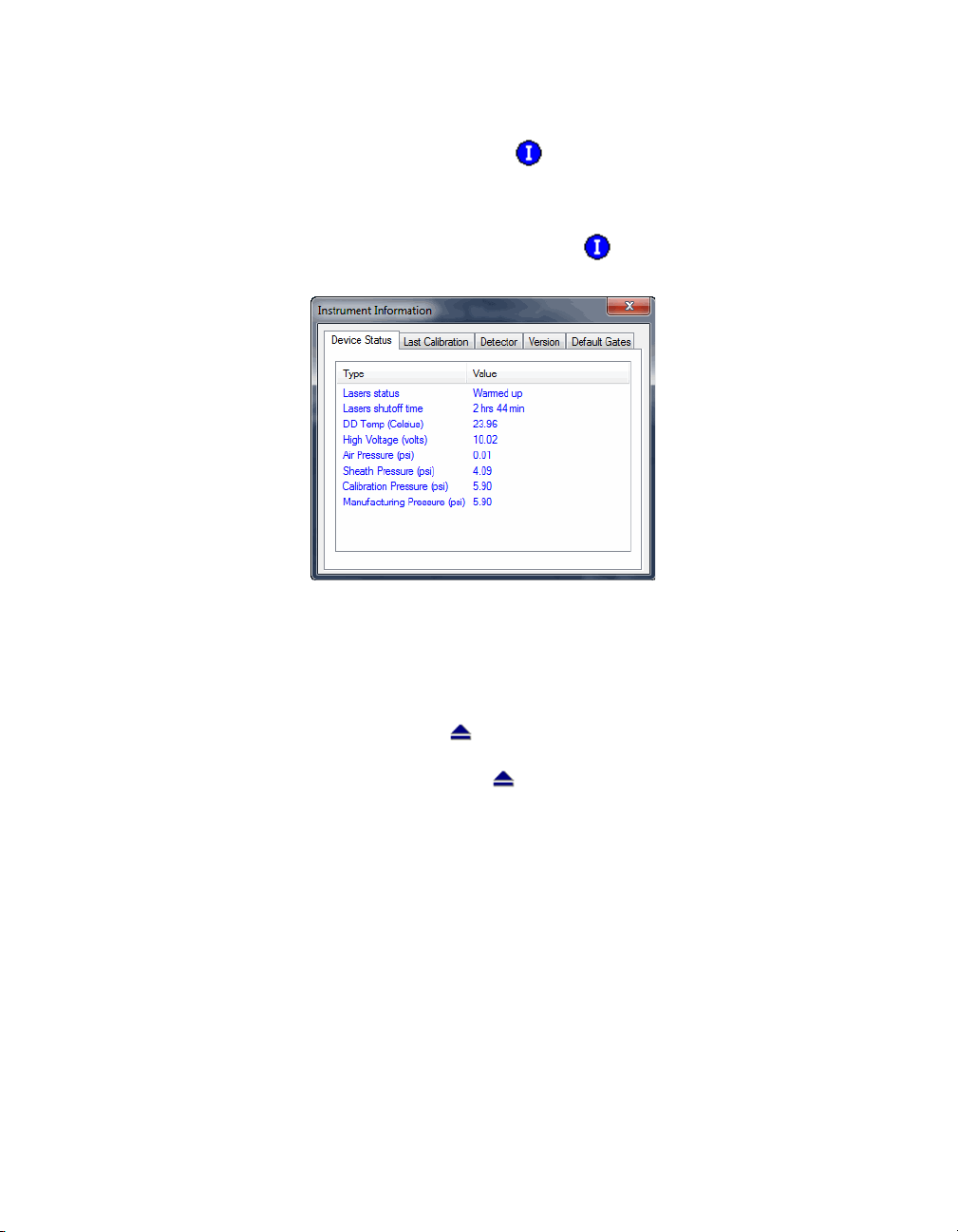
Instrument Information
The array reader continuously monitors its internal temperature, voltage,
pressure, and other systems for diagnostic purposes. You can access this
information by clicking the Information button on the main toolbar or
selecting Information from the Instrument menu.
Figure 34. Instrument Information dialog
Click the tabs in the dialog to access information about the instrument. See
the hardware manual for detailed instrument specifications.
Instrument Information
Eject/Retract Plate
The Eject/Retract Plate command on the main toolbar and Instrument
menu ejects and retracts the plate carrier in the microplate platform.
Note that every function that requires insertion of a plate into the platform (for
example, startup, wash, calibrate, etc.) includes an Eject/Retract button in its
dialog box.
Additional Instrument Functions
The Additional Functions submenu under the Instrument menu contains
secondary instrument fluidics functions. Selecting one of these commands
opens a dialog box to guide you through the procedure. Many of these
functions require the use of the Bio-Plex MCV Plate IV.
49
Page 62

Bio-Plex Manager Software 6.1 User Guide | Controlling the System
NOTE: Major fluidics functions, such as Wash Between Plates, Remove
Bubbles, and Unclog, consist of combinations of the following functions.
To perform each of the following functions, select it from the Additional
Functions submenu of the Instrument menu and follow the steps in the dialog
box that appears.
WASH
The Wash command performs a single fluidics system wash using distilled or
deionized water. It can be used to remove traces of sample in the fluidics
pathway. Note that this procedure is less comprehensive than Wash Between
Plates (page 38).
DRAIN
This command completely drains the fluidics system of the array reader—for
example, if you need to move the instrument. Make sure you have enough
room in your waste fluid container to prevent overflow.
PRIME
This command primes the fluidics system with sheath fluid.
50
SANITIZE
This command performs a comprehensive cleansing of the fluidics system
using 10% bleach.
ALCOHOL WASH
This command performs a single fluidics system wash using 70%
isopropanol.
ALCOHOL FLUSH
This command performs a comprehensive cleaning of the fluidics system
using 70% isopropanol.
BACK FLUSH
This command flushes sheath fluid through the fluidics system in the opposite
direction of sample flow, to remove particle obstructions from the cuvette.
Page 63

Cancel Operation
The Cancel button, located in the status bar at the bottom of the Bio-Plex
Manager window, can be used to cancel many of the instrument functions,
including calibration, validation, or any of the fluidics functions. Click the
Cancel button to cancel the current operation. An alert box prompts you to
confirm the cancellation.
Figure 35. Cancel button in the status bar
Shut Down
The shutdown procedure consists of a series of functions designed to clean
the fluidics lines and prevent a buildup of debris within the system.
To initiate this process, select Shut Down from the main toolbar or
Instrument menu, and follow the instructions in the dialog box.
Shut Down
Figure 36. Shut Down dialog
Instrument Operations Log
Each instrument operation you perform with Bio-Plex Manager is recorded in
the Instrument Operations Log. This log is stored in a secure database file
called bioplexdata.mdb. By default, this log is saved in the main Bio-Plex
Manager application folder on your computer.
51
Page 64

Bio-Plex Manager Software 6.1 User Guide | Controlling the System
NOTES: If you install Bio-Plex Manager 4.0 or later, the data from your
existing database (bioplex.mdb) copies into the new database
(bioplexdata.mdb). A copy of your old database will remain in the application
folder.
This Instrument Operations Log did not exist in Bio-Plex Manager versions
before 4.0, so if you are installing Bio-Plex Manager 6.1 over versions earlier
than 4.0, no Instrument Operations data will be copied.
To view this log, go to the View menu and select Instrument Operations Log.
The log viewer opens.
52
Figure 37. Instrument Operations Log Viewer
Each instrument operation is listed by date and time. If you are using Bio-Plex
Manager Security Edition in Secure Mode, the User and Access Level
columns list information about the user who was logged into the application
when each operation was performed.
To print the log, click the Print button .
To copy the information in the log to the Windows clipboard and paste it into
another document, drag your cursor over the rows and columns in the table to
select them, and use the Ctrl + C key command to copy the data.
Page 65

Bio-Plex Manager Software 6.1 User Guide
6 Preparing Protocols
Protocol Files
A protocol file contains the parameters of a Bio-Plex Manager™ 6.1 software
reading. It specifies the analytes used in the reading, the plate wells to be
read, sample information, the values of standards and controls, and
instrument settings.
When the reading is complete, the parameters in the protocol file are copied
into the Results file, along with the data from the reading.
You can save protocol files and reuse or modify them for other readings. Raw
data from the most recent reading is stored in the protocol file, and you can
generate a new Results file from this data.
Creating/Opening Protocol Files
To create a new protocol file, click the New Protocol button on the main
toolbar or Quick Guide, or select New Protocol from the File menu. A new
Protocol window opens.
To open an existing protocol file, click the Open Protocol button on the
Quick Guide or main toolbar, or select Open Protocol from the File menu.
Locate and select the file using the standard Windows Open dialog.
53
Page 66

Bio-Plex Manager Software 6.1 User Guide | Preparing Protocols
Standard protocol files have the file extension *.pbx. Secure protocol files,
created using Bio-Plex Manager Security Edition, have the file extension
*.spbx.
Multi-assay Standard Edition Protocols (see page 56 for more information)
have the file extension *.mpbx, and those saved with the Security Edition have
the file extension *.spbx.
NOTES:
• Secure protocol files can be opened only as read-only files using
the Standard (non-Security) Edition version of Bio-Plex Manager
• Protocol files created or modified by the current Bio-Plex Manager
cannot be opened by earlier versions of the software
You can generate a new protocol file from the settings stored in a Results file
(see page 143 for information about Results files). The new protocol may
include the data from the Results file or not, depending on the option you
select. From the File menu, select New Protocol from Results - Exclude Data,
or select New Protocol from Results - Include Data.
Saving Protocols
To save the settings in a protocol, click the Save button on the main
toolbar or select Save from the File menu.
After you have performed a reading (see Running the Protocol on page 108),
the data from that reading are also saved with the protocol file. These data are
overwritten in the protocol file whenever you rerun the protocol. To preserve
the data from multiple readings, you must save separate Results files (see
page 144).
Use Save As on the File menu to save a protocol under a different name. You
can create a new protocol by opening an existing protocol, modifying the
settings, selecting Save As, and specifying a new name for the modified
protocol.
54
Reducing the File Size of Protocols
Protocol files that include all the data from a reading can be very large
(>5 MB). Much of this file size is due to the raw bead event data from the
reading, which is used to generate the bead map and histogram displays. If
you require a smaller file size (for instance, to send the protocol file via email),
you can save a copy of the file without this raw bead event data, but with the
other numerical data from the reading intact.
Page 67

Protocol Files
NOTE: We strongly recommend keeping a copy of the original protocol file
with the raw bead event data intact. These data are necessary for changing
the DD gate range in the Results file, and can also be exported in XML file
format from the Results file for further analysis.
In the Save As dialog box, select the Compressed mode checkbox to save the
protocol file without the bead map and histogram data. All other data are
preserved.
Figure 38. Save As dialog for protocols
NOTE: This compressed file option is not available for secure protocol files
generated using the Security Edition of the software.
55
Page 68

Bio-Plex Manager Software 6.1 User Guide | Preparing Protocols
Multi-Assay Protocols
Bio-Plex Manager 6.1 has the ability to run multiple assays at one time. You
describe each assay, using Describe Protocol, in the same way as describing
single assays.
If you have chosen New Multi-Assay Protocol from the File menu, the
information you enter for each assay becomes its own tab, as outlined in red
in the figure below.
56
Figure 39. New Multi-Assay Protocol tabs
When an assay tab is clicked, the window displays all information connected
with the corresponding independent assay.
The assay number of the assay being displayed also appears in the title bar.
Uses for Multi-Assay Protocols
This functionality allows you to test the same, or different, samples with two or
more separate assays simultaneously. You can also run the same assay under
different conditions; for example, when you are in the optimization phase of
assay development.
Page 69

Multi-Assay Protocols
Creating a Multi-Assay Protocol
1. Choose New Multi-Assay Protocol from the File menu. This action
creates two tabs on the left pane, called Assay 1 and Assay 2.
2. Enter the protocol settings for Assay 1, then save.
3. Click on the Assay 2 tab, currently located at the bottom of the left
pane. It will jump to a position under the tab for Assay 1.
4. Enter the protocol settings for the second assay into the right hand
pane, then Save.
NOTE: Results of multi-assay protocols are always stored in separate results
files. Each assay results file is stored under its own descriptive name, such as
Bio-Plex Pro Human Group II.rbx.
NOTE: Choosing the New Results from Protocol command from the File menu
will generate results only for the assay that is currently open.
Changing a Protocol from Single to Multi-Assay
A Multi-Assay Protocol can also be created from a single assay protocol.
1. Open the single assay protocol and right click on the Protocol Settings
tab in the left pane of the Protocol window.
2. Select Add Assay. A message will open telling you that a new MultiAssay Protocol must be created.
3. Select Yes, then complete the protocol settings for each assay.
57
Page 70

Bio-Plex Manager Software 6.1 User Guide | Preparing Protocols
Protocol Window
The Protocol window steps you through a series of windows..
Figure 40. Protocol window
The buttons are numbered to guide you through defining your protocol:
58
1. Describe Protocol (optional) (see page 59).
2. Select Analytes (see page 59).
3. Format Plate (see page 68).
4. Enter Standards Info (see page 78).
5. Enter Controls Info (see page 96).
6. Enter Samples Info (optional) (see page 98).
7. Run Protocol (see page 108).
Page 71

Protocol Window
Click each setting button and enter the necessary information, then select the
next setting. After all the settings have been specified, you are ready to run
the protocol.
Step 1. Describe Protocol
The Protocol description window displays when you first open a protocol.
(Otherwise, click the Describe Protocol button to display this window.)
Entering a description of your protocol is optional.
If you are using the Standard Edition of the software, the Author field contains
your computer login name. You can enter a new name in the field, if desired,
and a description of the assay reading. If you are using the Security Edition,
the field contains your user name, which cannot be changed. Enter a
description of the assay reading in the Description field.
The Assay Lot field can be used to maintain a record of the lot number of the
assay. If you are using the Security Edition, Supervisor-level users are the only
users who can edit the Assay Lot field in the Describe Protocol window. If you
want to control the lot number associated with a protocol, enter it on the
Describe Protocol window. Then, whenever the protocol is run, the assigned
lot number will be associated with the results. If, however, the protocol will be
used with different assays, then leave the field blank on the Describe Protocol
window. Any users who run the protocol will be able to enter the assay lot
number for that particular experiment in the Run Protocol window, and this
information gets stored with the results.
Supervisor-level users can change the Assay Lot value in both the Describe
Protocol and Run Protocol windows. It is assumed that when a value is
entered in the Describe Protocol window, the purpose is to associate a
particular lot number with both the protocol and the results, and the Assay Lot
field is synchronized in both places. If the Supervisor then changes the value
in the Run Protocol window, the value in the Describe Protocol window is
updated with this new value.
If you are using the Standard Edition of the software, there is no restriction on
who may edit the Assay Lot field when setting up or running the protocol.
Step 2. Select Analytes
In this step, you select the analytes that you want reported in the reading.
59
Page 72

Bio-Plex Manager Software 6.1 User Guide | Preparing Protocols
NOTE: During a reading, the array reader always detects all the analytes in the
sample, including any you have not selected. However, analytes that were
detected but not selected will, by default, not appear in the final reports and
tables. After a reading, you can go back and correct your selections in the
Protocol window and/or the Results file, and the detected analytes will appear
in the tables.
Click the Select Analytes button to view the analyte selection window.
Figure 41. Select Analytes window
Bio-Plex Manager groups analytes by panels. Preconfigured panels of
analytes are built into the software; these panels correspond to off-the-shelf
Bio-Plex assays, and include human, mouse, and rat cytokines and
phosphoproteins, plus the newer human angiogenesis, diabetes, isotyping
and acute phase assays. You can add to these existing panels of analytes, or
create new panels that contain only the analytes you use in your experiments.
Bio-Plex cytokine, phosphoprotein, and total target assays are available as
custom-mixed x-Plex™ assays. For repeat sample testing, these multiplex
assays are offered in one or ten 96-well plate formats. Select from the current
list of available assays, and Bio-Rad will mix and quality-test the coupled
beads and detection antibodies to order. You can obtain product information
and a catalog number for your custom-designed x-Plex assay by going to
www.bio-rad.com/bio-plex/x-plex.
First select the panel of analytes that you want reported, then select the
specific analytes.
60
SELECTING ANALYTES
Go to the Panel pulldown menu and select from the list of preconfigured
panels. The analytes in the selected panel display in the Available list.
Page 73

Protocol Window
Each analyte is listed by name and region number. The region number refers
to the region of a fluorescent color map used to identify the analyte's bead
set. Each bead set is embedded with specific quantities of two fluorescent
dyes; the combination of these fluorochromes, as detected by the array
reader, places the bead set within a unique region on the color map, thereby
identifying the set and its associated analyte.
To move an individual analyte into the Selected list, double-click it. Doubleclick an analyte in the Selected list to move it back.
Hold down the Shift or Ctrl key and click multiple analytes in the Available list
to select them as a group. Then click the Add >> button to move them over to
the Selected list. Use the << Remove button to return multiple selected
analytes back to the Available list.
Use Add All>> to move all the available analytes into the Selected list, and
<<Remove All to move them back.
Figure 42. Selecting the analytes to be reported
NOTE: Some analytes share the same region. Only one analyte per region can
be added to the Selected list.
CUSTOMIZING ANALYTES AND PANELS
Bio-Plex Manager comes preconfigured with a selection of panels and
analytes that Bio-Rad provides as Bio-Plex assays. You can edit these and/or
create new ones.
NOTE: If you have assay kits for analytes that are not included in Bio-Plex
Manager, you must add these analytes using the commands described in this
section.
61
Page 74

Bio-Plex Manager Software 6.1 User Guide | Preparing Protocols
CREATING A NEW PANEL OF ANALYTES
Click the Add Panel button in the Select Analytes toolbar to create a new
panel of analytes.
Figure 43. Creating a new panel of analytes
Enter a name for the new panel in the top
field. Select the matching Assay type
from the Assay drop-down menu, which
is used to ensure the correct defaults.
Then click Add to add the analytes. The
Add Analyte dialog box opens.
Figure 44. Adding a new analyte
Enter the bead region number of the first analyte in the Region field, and the
analyte name in the Name field.
NOTE: The bead region number must be correct for proper detection of
analytes. Confirm this number is correct before proceeding.
Click Add Continue to add the analyte to the panel and continue adding more
analytes. When you have entered your last analyte, click the Add button to
add it to the list and close the Add Analyte dialog.
After you add several analytes to the panel you are creating, you can use the
Sort buttons at the bottom of the Add Panel dialog to sort them.
62
Page 75

Protocol Window
Click an analyte in the list to
select it, then click the
appropriate arrow to move it up
or down in the list.
Figure 45. Sorting analytes
You can also remove an analyte
from the list by selecting it and
clicking the Remove button, or
you can remove all analytes, by
clicking the Remove All button.
To edit an analyte in the list, select it, then click the Edit button. A dialog box
opens in which you can change the analyte region and name.
When you are finished creating the panel, click OK to save your changes and
return to the Protocol window.
IMPORTING A PANEL OF ANALYTES
Follow these steps to import a new panel.
1. Open Excel and create a Regions and Analytes list as shown. You may
choose to include the Panel name, as shown, or omit it.
2. Save this as a CSV file by choosing Save As from the File menu.
Choose CSV (MS-DOS) from the Excel Save as type drop-down list.
Figure 46. Saving a CSV File in Excel
63
Page 76

Bio-Plex Manager Software 6.1 User Guide | Preparing Protocols
3. Import this CSV file into Bio-Plex Manager by choosing the import
button in the Add Panel dialog.
Figure 47. Add Panel Dialog Box
4. Navigate through your file system to where you have saved the CSV file.
64
5. Click on the file to highlight, and press the Open button.
Figure 48. Importing the CSV File
Page 77

Protocol Window
6. The new panel will be added to the list of panels in Bio-Plex Manager.
Figure 49. Imported Panel
65
Page 78

Bio-Plex Manager Software 6.1 User Guide | Preparing Protocols
EDITING A PANEL OF ANALYTES
To edit an existing panel of analytes, first select it from the Panel pulldown
menu in the Select Analytes window. Then click the Edit Panel button .
The Edit Panel dialog box opens.
66
Figure 50. Editing a panel
Use the New, Edit, Remove, Remove All, and Sort buttons as described on the
preceding pages to change the analytes in the panel.
If you change the Panel Name, the changes are saved under the new name,
and the old panel will not be overwritten.
NOTE: The preconfigured Bio-Plex panels (Human Cytokines, Mouse
Cytokines, etc.) can be edited but not overwritten; therefore, you must change
the panel name to preserve your changes. When you are satisfied with your
changes, click OK.
Page 79

Protocol Window
DELETING AND RENAMING CUSTOM PANELS
To delete a custom panel of analytes:
1. Select it from the Panel pulldown menu in the Select Analytes window.
2. Click the Remove Panel button . You are asked if you are sure you
want to delete the panel.
Figure 51. Delete Panel Alert
To rename a custom panel of analytes:
1. Select it from the Panel name pulldown menu.
2. Click the Rename Panel button .
3. Enter a new name in the pop-up dialog box, and click OK.
Figure 52. Rename Panel Dialog
COMBINING PANELS OF ANALYTES
To combine entire panels of analytes (for example, Human Cytokines I and
Human Cytokines II) without going to the trouble of creating custom panels:
1. Select the panels individually from the pulldown list.
2. Use the Add All>> command to move the analytes from each panel into
the Selected list.
3. Save the entire protocol as you would normally.
Your analyte selections are saved when you save the protocol.
67
Page 80

Bio-Plex Manager Software 6.1 User Guide | Preparing Protocols
Step 3. Format Plate
After you have selected analytes, you are ready to specify the format of your
96-well microtiter plate using the plate template in the Protocol window. The
formatting in the plate template tells the array reader which wells to read, and
tells Bio-Plex Manager how to analyze the different sample types in each well.
NOTE: Only formatted wells will be read by the array reader. Be careful to
format all the wells that you want to read before running a protocol.
Click the Format Plate button in the Protocol window to display the plate
template and the formatting controls.
68
Figure 53. The plate template and formatting toolbar (Plate Formatting view)
The Format Plate window has two views: the Plate Formatting view and the
Plate Groupings view. You can toggle between the views using the tabs above
the plate diagram. As you toggle, the plate template remains the same, but the
commands toggle between formatting controls and grouping controls.
• Plate formatting tools are used to define the types of wells in a
plate (sample, control, standard, blank, etc.)
• Plate groupings tools are used to organize the well types into
groups, with one member of each group defined as the Reference
(or Primary) member, as in a Western blot kinase assay. The ratio of
each member's fluorescent intensity to the fluorescent intensity of
the Reference can then be calculated
NOTE: Plate formatting is required to perform a reading, because the array
reader will read only formatted wells, whereas plate groupings are optional
and can be defined later.
Page 81

Protocol Window
PLATE FORMATTING
To format the well types on the plate, select the Plate Formatting tab. Then
use the buttons on the toolbar above the plate template to define the wells on
the microtiter plate. These formatting commands are also located on the
Format Options menu.
Figure 54. Plate formatting tools (Plate Formatting view).
The different well types you can select are:
Unknown sample
Standard
Control
Blank
Undefined*
*Remember that all undefined wells are not read by the array reader.
DEFINING UNKNOWN SAMPLE WELLS
To define wells containing unknown samples, first click the Unknown Sample
button , then click or drag the wells in the template. Use the Autofill
buttons as described on the following page for defining multiple unknown
wells and/or replicate groups of unknowns.
Figure 55. Defining unknown sample wells
69
Page 82

Bio-Plex Manager Software 6.1 User Guide | Preparing Protocols
Note that the cursor changes to an Unknown Sample cursor as you move it
over the template. As you select each well, it is marked with a square and a
number at the center. The square identifies the well as containing an unknown
sample, and the number identifies the specific sample.
The Set Number of Unknown Samples command is available only in the
Security Edition of the software. For more information about the Security
Edition, see the Appendix on page 219.
WELL NUMBERING AND REPLICATE GROUPS
For unknowns, standards and controls, wells with different numbers contain
different samples. Wells with the same number contain the same sample, and
are defined as a replicate group. For each replicate group, a mean value is
calculated in the Report table, along with the standard deviation and
coefficient of variation.
AUTOFILLING WELL NUMBERS
To define multiple single wells as different samples, you can click them
individually, or select Autofill Across or Autofill Down and drag the
cursor over the wells to number them sequentially.
70
Figure 56. Defining multiple sample wells with Autofill
Note that Autofill Across numbers the wells sequentially left to right, then top
to bottom, while Autofill Down numbers them sequentially top to bottom, then
left to right.
Page 83

Protocol Window
DEFINING A REPLICATE GROUP
To define multiple wells as a replicate group, select Turn Off Autofill from
the formatting toolbar or Format Options menu, then drag your cursor over
several wells that contain the same sample. The wells are labeled with the
same number.
Figure 57. Defining a replicate group of unknowns
For each replicate group, a mean value is calculated, along with the standard
deviation, standard error, and coefficient of variation.
AUTOFILLING REPLICATE GROUPS
If you have multiple replicate groups of wells in rows or columns, you can
autofill these by selecting Autofill Across or Autofill Down as before, and then
entering the number of wells in the replicate group (up to 96) in the number
field next to the autofill buttons. (You can also select well numbers up to 10
from the pulldown menu.)
Figure 58. Entering the number of replicate wells in an Autofill sequence
Now when you drag your cursor, the sequential sets of replicate wells are
defined.
Figure 59. Autofilling a sequence of replicate groups
For each replicate group, a mean value is calculated, along with the standard
deviation, standard error, and coefficient of variation.
71
Page 84

Bio-Plex Manager Software 6.1 User Guide | Preparing Protocols
CHANGING A REPLICATE GROUP
To change the replicate group of a well or group of wells:
1. Click the Select tool , and click or drag the wells you want to change.
The wells appear highlighted.
2. Right-click the selection, and select Set Replicate Group from the
context menu.
3. In the pop-up box, select the desired replicate group number from the
pulldown list.
4. Click OK. The selection is changed to the specified group number.
Figure 60. Selecting a different replicate group
72
RESEQUENCING WELL NUMBERS
If your well numbering is out of sequence and you want to correct it, select
Resequence Well Names from the Format Options menu. All the wells in the
plate are renumbered sequentially, based on whether you have selected
Autofill Across or Autofill Down. This is a cosmetic change, and does not
affect the analysis in any way.
DEFINING STANDARD WELLS
Standard wells contain analytes of known concentration, which are used to
generate a standard curve of fluorescence intensity versus analyte
concentration. The regression equation for the curve is then used to calculate
the concentrations of your unknowns.
Page 85

Protocol Window
To define the wells containing standards in your microtiter plate, click the
Standard button , then click or drag the wells in the template. Use the
Autofill buttons as described on page 70 to define multiple standard wells
and/or replicate groups of standards.
Figure 61. Defining a row of standard wells
NOTES:
• The cursor changes to a Standard cursor as you move it over the
template. Standard wells are marked in the template by a circle
with a number inside it.
• After you have defined the standard wells, you are ready to enter
the concentrations of the standards as described on page 91.
DEFINING CONTROL WELLS
Control wells contain samples of known concentration; the expected vs.
observed concentrations of the controls can be calculated at the end of the
reading.
To define the wells containing controls in your microtiter plate, click the
Control button , then click or drag the wells in the template. Use the
Autofill buttons as described on page 70 to define multiple control wells and/
or replicate sets of controls.
Figure 62. Defining a row of control wells
73
Page 86

Bio-Plex Manager Software 6.1 User Guide | Preparing Protocols
Note that the cursor changes to a Control cursor as you move it over the
template. Control wells are marked in the template by an octagon with a
number inside it.
NOTE: After you have defined the control wells, you are ready to enter the
concentrations of the controls as described on page 96.
DEFINING BLANK WELLS
In certain types of assays such as the Bio-Plex phosphoprotein assay, it may
be useful to subtract the assay background from the readings of standards,
controls, and unknown samples. To do this, you can prepare "blank" wells
containing all the assay components except sample. Wells prepared as blanks
are read along with the rest of the assay, and then Bio-Plex Manager subtracts
the mean background reading of these wells from the fluorescence intensity
values of the wells containing standards, controls, and unknowns.
To format blank wells in the plate template, click the Blank button , then
click or drag the blank well(s) in the template. Note that the cursor changes to
a Blank cursor as you move it over the template.
74
Figure 63. Defining a row of blank wells
Blank wells are marked in the template with a diamond shape containing the
letter B.
Multiple blank wells in a template are treated as a single replicate group. A
mean value, standard deviation, standard error, and coefficient of variation are
calculated for the group, and the mean is used as the background value.
DELETING OR CHANGING WELL FORMATTING
To delete the formatting from a well or set of wells, select Undefined from
the toolbar or Format Options menu, then click or drag the well(s) you want to
clear. To clear the formatting from all wells in the template, select Clear Plate
from the Format Options menu. To change the formatting of a well or group of
wells, simply select the appropriate tool and overwrite the old formatting, as if
you were defining the wells for the first time.
Page 87

Protocol Window
Plate Groupings
After you have formatted the wells (see previous section), you can organize
them into groups and identify one member of each group as the Reference, or
Primary member. You can then calculate the ratio of each member's
fluorescence intensity to the fluorescence intensity of its Reference. This type
of analysis is similar to that performed in Western blotting.
Click the Plate Groupings tab to display the plate grouping tools.
Figure 64. Plate Groupings view
The buttons on the toolbar are used to group the wells on the microtiter plate
diagram and identify the Reference well(s). These formatting commands are
also located on the Format Options menu.
Figure 65. Tools in the Plate Groupings view
First, select the ratio you want to calculate for each group — Reference/
Member or Member/Reference — using the Ratio field pulldown list.
75
Page 88

Bio-Plex Manager Software 6.1 User Guide | Preparing Protocols
DEFINING A GROUP
To define an assay group, click the Group button and drag the cursor
across the wells you want to group.
NOTES:
• Wells must be defined as Unknown samples, Standards, Controls,
or Blanks before they can be grouped.
• You can group across well types (for example, a single group can
include Standards, Unknown samples, Controls, and/or Blanks).
• Replicate wells are automatically placed in the same group (even if
you drag over only one well in the replicate set).
Figure 66. Defining a group of wells
The grouped wells change color to indicate their grouping, and the first
member of the group is highlighted to indicate that it is defined as the
Reference well.
Each group you create will be designated with a different color.
To remove individual members of a group or the entire group, click the
76
Ungroup Samples button and click or drag over the members/group.
Note that you can also use the Select tool to first select a group of wells,
and then use the Set Sample Group command on the Format Options menu
or context menu to select the group.
Page 89

Protocol Window
CONTEXT MENU
Right-click and drag over a number of formatted cells to bring up a context
menu, that allows you to change several settings, including dilution factor,
replicate group, and sample description.
Figure 67. Right-click context menu
DEFINING THE REFERENCE
To change the Reference member of the group, click the Reference
button and click the desired Reference member in the group. For replicates,
all replicate wells of the same number within the group are automatically
designated as the same Reference.
You can also use the Select tool to first select the Reference well within a
group and then use the Set Sample as Reference Member command on the
right-click context menu to set the Reference.
PRINTING THE PLATE FORMAT
To print the plate format for your records, select Print from the File menu, or
click the Print button on the main toolbar. For a preview of the printed
format, select Print Preview from the File menu.
77
Page 90

Bio-Plex Manager Software 6.1 User Guide | Preparing Protocols
Step 4. Enter Standards Info
This section describes how to enter information about your standards. To
enter information for standard wells defined on the current plate, make sure
the Standards Info tab is selected.
Standards are analytes of known concentration. They are used to generate a
standard curve of values using one of the several regression methods built
into Bio-Plex Manager. This curve is used to calculate the concentrations of
your unknowns.
The standards you select depend on the performance characteristics of your
assay, and the type of curve-fitting model you want to use. Due to variations in
assay preparation, we recommend using a minimum of eight standard
concentrations to generate the standard curve. See the appropriate Bio-Plex
Assay Instruction Manual for recommendations of standard concentrations.
To see what manuals are available, visit www.bio-rad.com/bio-plex.
The minimum number of non-zero standards required for each type of
regression method available in the software is shown in the following table.
Method Minimum number of standards
Logistic-5PL 6
Logistic-4PL 5
Cubic spine 4
Linear (linear and semi-log) 2
Point to point (linear and semi-log) 2
78
Before entering the concentration values of your standards, you must select
the analytes that you will be analyzing in the reading as described on page 59.
If your current plate contains your standards, you must also identify the
standard wells as described on page 72.
Page 91

Protocol Window
Click the Enter Standards Info button in the Protocol Settings pane to enter
information about your standards.
Figure 68. Entering information about standards
The Enter Standards Info window allows you to define standards on your
current microtiter plate, and/or import external standards data from another
plate. Use the tabs above the data fields to select between standards on the
current plate and external standards.
NOTE: You can define standards on the current plate and import external
standards in the same protocol. This is useful if you want to run standards for
some analytes on the current plate, but include external standards for other
analytes in your concentration calculations. Note that if external standards
and current standards are defined for the same analyte, the external
standards will always be used to calculate the concentrations of that analyte.
Standard Lots
You can create, reuse, and import standard lots to ensure repeatable results
between experiments and/or researchers in a workgroup.
This function eliminates the need for you to enter or re-enter this data
manually.
Click the Enter Standards Info button in the Protocol Settings pane. Choose
the Standards Info tab.
79
Page 92

Bio-Plex Manager Software 6.1 User Guide | Preparing Protocols
The Standard Concentration Lot window is at the top of the screen.
Figure 69. Standard Concentration Lot window
LOADING A STANDARD LOT INTO YOUR PROTOCOL
80
If you have previously saved a standard lot or it is otherwise present in your
current version of Bio-Plex Manager, you can quickly load it into your protocol
by using the load function.
Figure 70. Load Standard Lot button
This will result in the following window which will display all the lots loaded
into your version of Bio-Plex Manager. Choose the lot you want to use and
press OK. This will load the concentration and dilution information associated
with this lot.
Figure 71. Load Standard Lot dialog
Page 93

Protocol Window
MANAGING STANDARD LOTS
You can import new lots, export lots to collaborators, or delete lots on your
Bio-Plex Manager by using the Manage Standard Lots function.
Figure 72. Manage Standard Lots
Pressing the Manage Standard Lots button brings up a dialog that allows you
to import, export and delete standard lots.
Figure 73. Manage Standard Lots screen
Importing Standard Lots—Standard lots will be added continually to the
Bio-Rad web site, which can be accessed in the help menu of Bio-Plex
Manager. Download the lot file (which is in XML format) from the web site to
your PC and then choose Manage Lots (above) and press the Import button
from the resulting window. You can import all or a subset of the lots present in
this file.
Exporting Standard Lots—You can export all or a selected number of lots to
collaborators by pressing the Export button. When you export the lots they
are saved in an XML format which can be sent to other users of Bio-Plex
Manager for import.
Deleting Standard Lots—Unneeded standard lots are deleted by pressing
the Delete button.
81
Page 94

Bio-Plex Manager Software 6.1 User Guide | Preparing Protocols
ENTERING STANDARD LOTS MANUALLY
If your lot is not preloaded in the software or you cannot find it on the Bio-Rad
web site, you can enter the information manually from the product insert. You
can save any manually entered standard information as a new standard lot, as
described above.
Kits fall into two categories; those which have various starting concentrations
and those which have the same starting concentration for each analyte.
When starting concentrations vary across all analytes—There are a
number of ways to edit values and apply dilutions. The following outlines the
most efficient approach.
1. Enter the starting concentration of each analyte directly in the
spreadsheet within the interface. Enter each analyte before proceeding
to the next step. Make sure the “Apply same concentration to all
analytes” box is unchecked (default)
82
Page 95

Protocol Window
2. Once each analyte’s starting concentration is entered, apply the dilution
factor which is appropriate for your experiment.
Figure 74. Applying the Dilution Factor
3. The software will calculate all the concentrations for each analyte at
each dilution, as seen below.
Figure 75. Bio-Plex Manager calculates concentrations
83
Page 96

Bio-Plex Manager Software 6.1 User Guide | Preparing Protocols
When starting concentrations are the same across all analytes—follow
the following steps.
1. Check the box next to Apply same concentration to all analytes. This is
not the default setting.
2. Enter the starting concentration in the box indicated in the image below.
84
Page 97

Protocol Window
3. Enter the dilution factor and press calculate.
4. The software calculates all the concentrations for each analyte and at
each dilution, as seen below.
85
Page 98

Bio-Plex Manager Software 6.1 User Guide | Preparing Protocols
DELETING STANDARDS
To delete your Standards entries, click in the spreadsheet title called “Std” to
highlight all entries as shown below. Press the Delete button on your keyboard.
Figure 76. Deleting Standards Entries
86
Page 99

Protocol Window
SELECTING EXTERNAL STANDARDS
This section describes how to select a Results file from which to import
external standards data into a protocol.
Click the Select External Standards tab. In the window, click the Fill Available
List button, navigate to the directory containing the Results file with your
standards of interest, and select the file. (Note that the Open dialog displays
only Results files.)
Figure 77. Selecting the Results file that contains external standards
The Available External Standards list will be populated with the standards
from the selected file. To add additional standards, repeat the procedure,
selecting a different file.
To delete all standards from the Available list, click the Clear Available List
button.
To make the available external standards accessible in the current protocol,
you must add them to the Selected External Standards list (right-hand pane).
To add all of the standards in the Available column, click the Add All>> button.
To add available standards individually, double-click them, or select multiple
analytes using Shift + click and Ctrl + click key combinations and click the
Add>> button.
(Use the <<Remove and <<Remove All buttons to deselect them.)
87
Page 100

Bio-Plex Manager Software 6.1 User Guide | Preparing Protocols
NOTE: Each external standard you select must match the region of a selected
analyte in the protocol. For example, if you selected analytes in regions 19, 32,
52, and 73 in the Select Analytes window (page 59), you can select only
external standards in those same regions. (Note that the analyte name does
not have to match, only the region.) Also, each analyte must come from a
different region.
When you are finished, the Selected External Standards list should include all
the analytes that you want to use as external standards, and their source
file(s).
Figure 78. Selected external standards
Click the External Standards Info tab to enter additional information about
your external standards.
88
 Loading...