

Page 1
Instructions for Use for
Bio-Plex Pro™
& Bio-Plex Pro II
Wash Stations
Revision B
Attention!
Use only the magnetic carrier which arrived with your instrument.
See page 17 for more details.
Page 2

ii Bio-Plex Pro and Bio-Plex Pro II Wash Stations
Page 3

Notice
Every effort has been made to avoid errors in text and diagrams; however,
Bio-Rad Laboratories assumes no responsibility for any errors that may appea r in this
publication.
Bio-Rad reserves the right to change specifications at any time with appropriate
validation, verification, and approvals.
Copyright Information
The contents of this document are the property of Bio-Rad Laboratories and are not
to be copied, reproduced, or transferred to another person or persons without written
permission.
Copyright ©2008 Bio-Rad Laboratories
All rights reserved.
Declaration of Conformity
See page 79.
About the Instructions for Use (IFU)
This document describes the use of the Bio-Plex Wash Stations, designed for
performing hands-free wash programs on Bio-Plex and other xMAP assays.
It contains instruction for the use of the instrument and is intended as a reference for
the user. It contains information about the following:
• Installing the instrument
• Operating the instrument
• Programming of wash programs
• Definition of wash parameters
• Cleaning and maintenance procedures
Trademarks
The following product names and any registered or unregistered trademarks
mentioned in this document are used for identification purposes only and remain the
exclusive property of their respective owners:
• Microcide is a registered trademark of Global Biotechnologies Inc., Portland,
Maine, USA
• MagPlex and xMAP are trademarks of Luminex Corporation, Austin, TX, USA
• Tween is a registered trademark of ICI Americas, Inc., Wilmington, DE, USA
• Decon and Neutracon are registered trademarks of Decon Laborat ories Limited,
Sussex, UK
• HydroControl is a trademark of Tecan Group Ltd, Männedorf, Switzerland
Bio-Plex Pro and Bio-Plex Pro II Wash Stations iii
Page 4

iv Bio-Plex Pro and Bio-Plex Pro II Wash Stations
Page 5

Table of Contents
TABLE OF CONTENTS..........................................................................................................................................V
BASIC OPERATION AND MAINTENANCE ................................................................................................... 11
INSTRUMENT OPTIONS..................................................................................................................................... 11
MICROPLATE REQUIREMENTS ..........................................................................................................................12
INSTALLING THE INSTRUMENT........................................................................................................................... 13
Bio-Plex Pro Installation Diagram.............................................................................................................. 14
Bio-Plex Pro II Installation Diagram........................................................................................................... 15
Installing the Tubing Bracket (Bio-Plex Pro II only).................................................................................. 16
Selecting and Installing a Plate Carrier..................................................................................................... 17
Changing the Vacuum Configuration ........................................................................................................ 18
INSTALLING THE MICROPLATE .......................................................................................................................... 19
TURNING ON THE POWER................................................................................................................................. 19
KEYPAD BASICS.............................................................................................................................................. 20
Primary Menu............................................................................................................................................ 20
Secondary Menu ....................................................................................................................................... 20
PRIMING THE INSTRUMENT............................................................................................................................... 20
Failure to Prime......................................................................................................................................... 21
PLATE WASHING PROGRAMS........................................................................................................................... 22
WHICH WASH PROGRAM DO I USE?................................................................................................................. 23
Quick Guide............................................................................................................................................... 23
RINSING.......................................................................................................................................................... 24
RINSING.......................................................................................................................................................... 25
Rinse Day.................................................................................................................................................. 25
Rinse Night................................................................................................................................................ 26
Instrument state at the end of the wash.................................................................................................... 26
CHANGING THE PLATE CARRIER....................................................................................................................... 27
PREVENTIVE MAINTENANCE PLAN .................................................................................................................... 28
Daily........................................................................................................................................................... 28
Weekly....................................................................................................................................................... 28
Every Six Months....................................................................................................................................... 29
As Needed................................................................................................................................................. 29
Yearly (Service Engineer Required).......................................................................................................... 29
Bio-Plex Pro and Bio-Plex Pro II Wash Stations v
Page 6

REFERENCE SECTION .................................................................................................................................. 30
PURPOSE OF REFERENCE SECTION .................................................................................................................. 30
INSTRUMENT DETAILS.................................................................................................................................. 31
INSTRUMENT SAFETY....................................................................................................................................... 31
INTENDED USE................................................................................................................................................ 32
CONFIGURATIONS............................................................................................................................................ 33
INSTRUMENT SPECIFICATIONS ......................................................................................................................... 34
DESCRIPTION.................................................................................................................................................. 36
BIO-PLEX PRO DIMENSIONS ............................................................................................................................ 37
BIO-PLEX PRO II DIMENSIONS.......................................................................................................................... 38
REAR PANEL CONNECTIONS ............................................................................................................................ 38
REAR PANEL CONNECTIONS ............................................................................................................................ 39
DETAILED INSTALLATION ............................................................................................................................ 40
REQUIRED WORKING AREA.............................................................................................................................. 40
POWER REQUIREMENTS .................................................................................................................................. 40
UNPACKING AND INSPECTION CHECKLISTS ....................................................................................................... 40
DETAILED OPERATING INSTRUCTIONS..................................................................................................... 42
SWITCHING THE INSTRUMENT ON..................................................................................................................... 42
COMPLETE INSTRUMENT KEYPAD FUNCTIONS................................................................................................... 43
Alphabetical list of LCD text with explanations.......................................................................................... 45
DEFINING CUSTOM WASH PROGRAMS.............................................................................................................. 48
WASH MODES................................................................................................................................................. 48
Washing Positions..................................................................................................................................... 49
ASPIRATING MODES ........................................................................................................................................ 50
Normal AspirationMode............................................................................................................................. 50
Crosswise Aspiration Mode....................................................................................................................... 50
DRIP MODE..................................................................................................................................................... 51
DEFINING NEW PROGRAMS......................................................................................................................... 53
INTRODUCTION................................................................................................................................................ 53
PROGRAM MENU............................................................................................................................................. 53
DEFINE/EDIT A PROGRAM ................................................................................................................................54
Process Step: Aspirate.............................................................................................................................. 55
Process Step: Dispense............................................................................................................................ 56
Process Step: Wash.................................................................................................................................. 58
Process Step: Soak................................................................................................................................... 59
Process Step: User Prompt....................................................................................................................... 59
Process Step: Vacuum Filtration............................................................................................................... 59
SHOW PROGRAM............................................................................................................................................. 60
CLEAR PROGRAM............................................................................................................................................ 61
SETTINGS MENU ............................................................................................................................................. 61
Edit Plates ................................................................................................................................................. 62
Options Submenu...................................................................................................................................... 62
Vacuum Filtration....................................................................................................................................... 62
Bubble Sensor........................................................................................................................................... 63
PROCEDURES MENU ....................................................................................................................................... 63
Rinse ......................................................................................................................................................... 63
Prime......................................................................................................................................................... 63
Empty Prime Tray...................................................................................................................................... 63
MAINTENANCE AND CLEANING .................................................................................................................. 65
CLEANING PROCEDURES ................................................................................................................................. 65
vi Bio-Plex Pro and Bio-Plex Pro II Wash Stations
Page 7
Cleaning the Cover and Display................................................................................................................ 65
Cleaning the Liquid System....................................................................................................................... 65
Cleaning the Manifold................................................................................................................................ 66
Cleaning Waste Bottles............................................................................................................................. 66
LIQUID OR FOAM SPILLS .................................................................................................................................. 67
REPLACING THE MANIFOLD.............................................................................................................................. 68
Removing the Manifold.............................................................................................................................. 69
Installing the Manifold................................................................................................................................ 70
INSTRUMENT DISINFECTION ............................................................................................................................. 71
Disinfection Solutions................................................................................................................................ 71
Disinfection Procedure.............................................................................................................................. 72
DISPOSAL OF INSTRUMENT .............................................................................................................................. 73
Disposal of Operating Material..................................................................................................................73
Disposal of the Instrument......................................................................................................................... 73
TROUBLESHOOTING AND ERROR MESSAGES......................................................................................... 75
ERRORS WITHOUT MESSAGES......................................................................................................................... 75
ERROR MESSAGES.......................................................................................................................................... 75
Plate Error ................................................................................................................................................. 75
Program Too Big Error.............................................................................................................................. 75
Transport Error.......................................................................................................................................... 75
Manifold Arm Error .................................................................................................................................... 76
Sensor Defect Error................................................................................................................................... 76
RS485 Error............................................................................................................................................... 76
PC (Process Control) System Error .......................................................................................................... 77
No Aspiration at Vacuum Filtration Error................................................................................................... 77
LLD Errors................................................................................................................................................. 78
DECLARATION OF CONFORMITY................................................................................................................ 79
INDEX............................................................................................................................................................... 80
Symbols
Indicates the possible presence of biologically hazardous material.
Indicates the possible presence of a strong magnetic field.
Warnings, Cautions, and Notes
The following types of notices are used in this publication to highlight important
information or to warn the user of a potentially dangerous situation:
Information
Gives helpful information.
Caution
Bio-Plex Pro and Bio-Plex Pro II Wash Stations vii
Page 8
Indicates a possibility of instrument damage or data loss if instructions are not followed.
WARNING
Indicates the possibility of severe personal injury, loss of life, or equipment damage if the
instructions are not followed.
WARNING
This symbol Indicates the possible presence of biologically hazardous material. Proper
laboratory safety precautions must be observed.
Attention
Negative environmental impacts associated with the treatment of waste.
z Do not treat electrical and electronic equipment as unsorted municipal waste
z Collect waste electrical and electronic equipment separately
WARNING
Risk of fire and explosion!
Ethanol is flammable and when improperly handled can lead to explosions. Proper
laboratory safety precautions must be observed.
viii Bio-Plex Pro and Bio-Plex Pro II Wash Stations
Page 9

Abbreviations
A Ampere
°C Degrees Celsius
CE Conformité Européenne
cm Centimeter
CV Coefficient of Variation
ELISA Enzyme-Linked ImmunoSorbent Assay
EN European Norm: a voluntary European standard of the European Committee for
°F Degrees Fahrenheit
IEC International Electrotechnical Commission
IFU Instructions for Use
in. Inch
IVD In Vitro Diagnostics
IVD-D In Vitro Diagnostics Directive
kg Kilogram
l; L Liter
m Meter
mBar Millibar
ml Milliliter
mm Millimeter
mS Millisiemens
µl Microliter
PC Process Control
PCR Polymerase Chain Reaction
ppm Parts Per Million
QC Quality Control
REF Reference Numbe r/ Order Number
s Second
SN Serial Number
T Träge (Slow Blow Fuse)
torr Torr – Millimeter of Mercury (mmHg)
TYPE Name and Type of instrument
USB Universal Serial Bus
V Volt
VA Volt Ampere
WEEE Waste Electrical and Electronic Equipment
Standardization or Comité Européen de Normalisation (CEN)
Bio-Plex Pro and Bio-Plex Pro II Wash Stations ix
Page 10

Basic Operation and Maintenance
10 Bio-Plex Pro and Bio-Plex Pro II Wash Stations
Page 11

Basic Operation and Maintenance
Basic Operation and Maintenance
This section gives you instructions to configure, install, prime, and use the Bio-Plex
Pro™ and Bio-Plex Pro II Wash Stations. You can perform your first plate wash
simply by using these instructions and the onboard wash program. This section also
contains references to more detailed information throughout this manual.
Instrument Options
The Bio-Plex Pro and Bio-Plex Pro II Wash Stations are designed for strip-wise
washing of 96-well microplates. They are designed primarily for the processing of
Bio-Plex and other xMAP assays.
The wash station is available in two versions.
Wash Configuration Bio-Plex Pro Bio-Plex Pro II
Vacuum filtration No Yes
Magnetic separation Yes Yes
Both wash stations are delivered with the standard carrier installed and the
appropriate programs for performing your assays. Replace the standard carrier with
the appropriate carrier for your assays as outlined on page 17.
Which Wash Program Do I Use? On page 23 describes the standard wash programs
necessary for the different assays.
To run standard ELISAs or other plate-based assays, you must modify programs and
plate definitions, using the HydroControl™ software available on the CD that ships
with both instruments. This software is not needed for Bio-Plex or Bio-Plex Pro assay
processing. Follow the instructions in Defining New Programs on page 53.
Bio-Plex Pro and Bio-Plex Pro II Wash Stations 11
Page 12

Basic Operation and Maintenance
Microplate Requirements
Use recommended microplates. If you use different microplates, your
assay results may not be reproducible, and you may experience
excessive bead loss.
Recommended microplates for magnetic assays:
Bio-Rad Part # Description Default for Magnetic Products
171-025001
*For a complete list of suitable plates, please contact Bio-Rad technical support.
Only these recommended filter plates should be used with the Bio-Plex Pro II, when configured for standard
Bio-Plex or other polystyrene bead based xMAP assays.
Bio-Plex Pro
flat-bottom plates
Yes
Recommended microplates for vacuum filtration:
Vendor Manufacturer Part # Default for Vacuum
Products
Millipore MSBVS1210 Yes
If using other microplates, you will have to enter new microplate definitions, using the
Hydrocontrol software included on the CD. Please note the following requirements.
Parameters Characteristics
Max. overall microplate height 14.35 mm ± 0.76 mm
(0.5650 inches ± 0.0299 inches)
Footprint 9.0 mm (0.3543 inches)
Pitch size (center to center) 9.0 mm (0.3543 inches)
Bottom shape Round, V-shaped, and flat
12 Bio-Plex Pro and Bio-Plex Pro II Wash Stations
Page 13
Basic Operation and Maintenance
Installing the Instrument
Unpack the instrument and install the instrument according to the instructions below.
Additional helpful information is located on the following pages:
• Unpacking checklist on page 40
• Bio-Plex Pro installation diagram on page 14
• Bio-Plex Pro II installation diagram on page 15
Caution
Do NOT turn the instrument on until you have completed the
steps below.
Caution
Before the instrument is installed and switched on, it should be left to
stand for at least three hours, so there is no possibility of condensation
causing a short circuit.
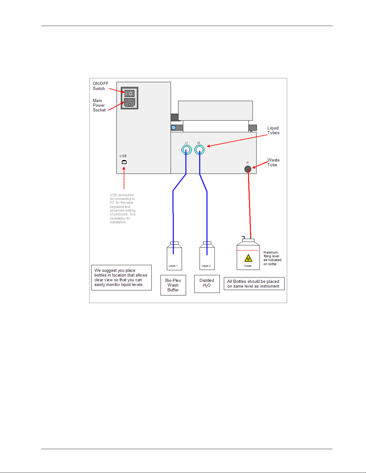
1. Ensure that the on/off switch in the rear panel of the instrument is in the off
position.
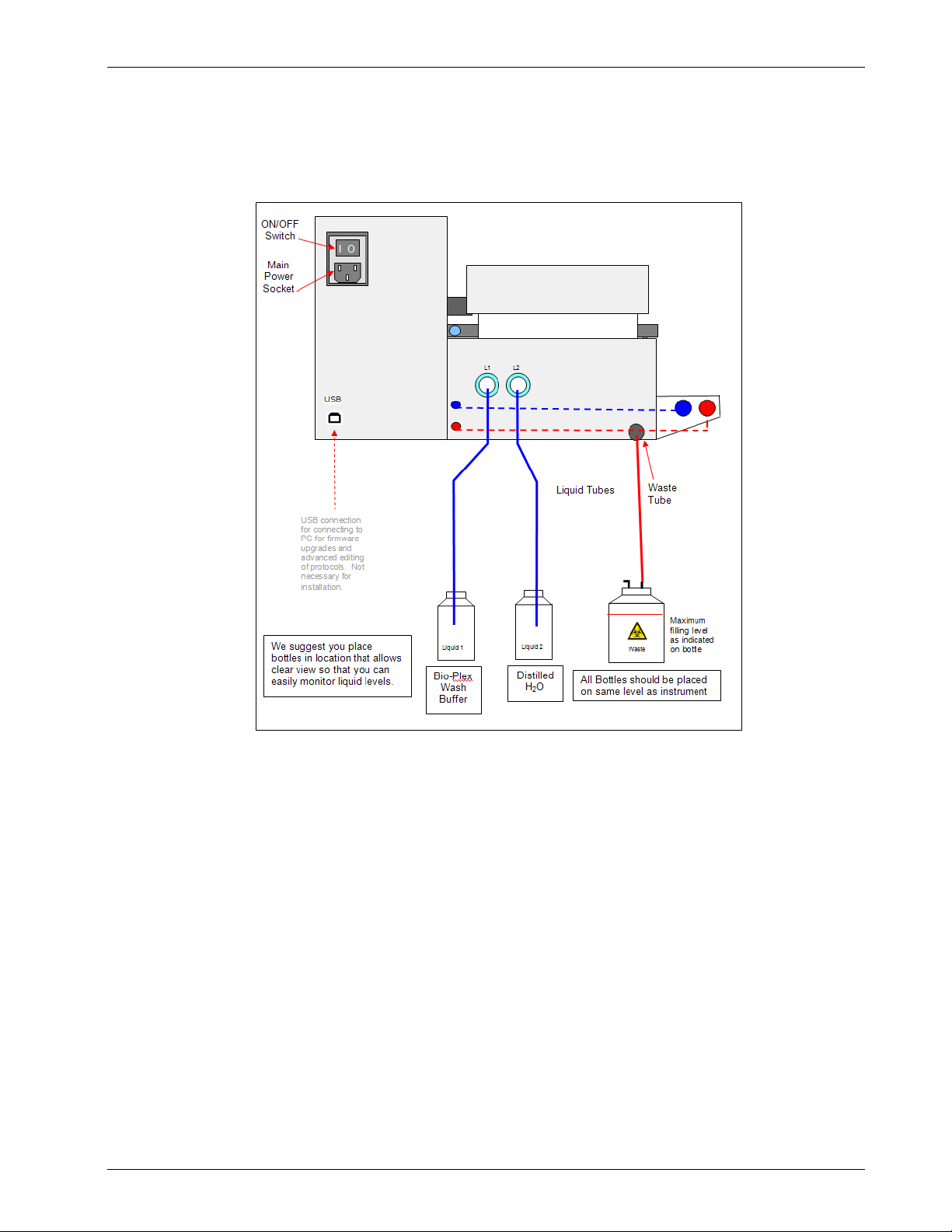
2. Connect the solution tubes (L1 and L2) to the inlet connectors on the rear
panel of the instrument. See the diagrams on the following pages.
3. Connect the solution tubes to the corresponding liquid bottles.
4. Connect the waste tube to the waste bottle (do not kink the tubes).
5. IF your instrument is a Bio-Plex Pro II, install the tubing bracket as shown on
page 16.
6. Fill Liquid 1 bottle with Bio-Plex wash buffer.
7. Fill Liquid 2 bottle with distilled or higher grade water.
8. Remove the standard ELISA carrier and install the appropriate plate carrier
based on the assays you will be running (Selecting and Installing a Plate
Carrier on page 17).
Bio-Plex Pro and Bio-Plex Pro II Wash Stations 13
Page 14
Basic Operation and Maintenance
Bio-Plex Pro Installation Diagram
14 Bio-Plex Pro and Bio-Plex Pro II Wash Stations
Page 15
Basic Operation and Maintenance
Bio-Plex Pro II Installation Diagram
Bio-Plex Pro and Bio-Plex Pro II Wash Stations 15
Page 16
Basic Operation and Maintenance
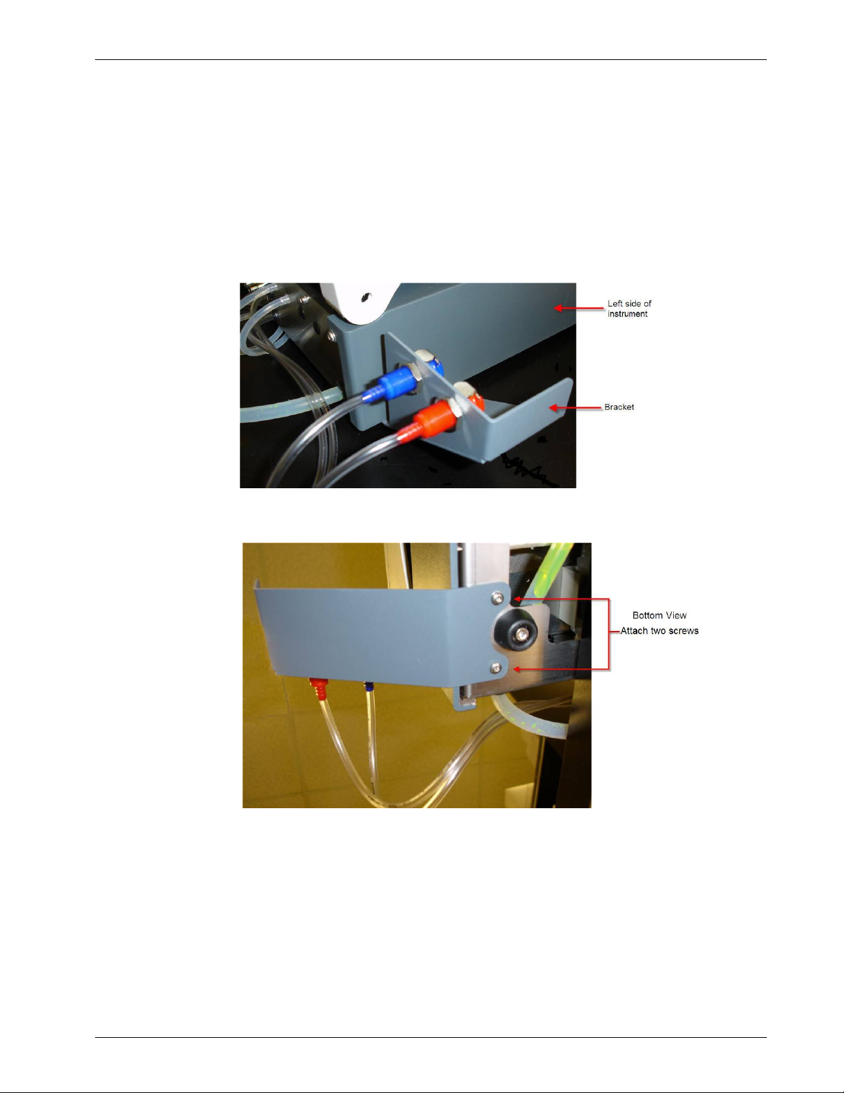
Installing the Tubing Bracket (Bio-Plex Pro II only)
Your Bio-Plex Pro II is shipped with the liquid hoses attached. Attach the tubing
bracket to the left side of the instrument, as shown in the pictures below.
Location of Tubing Bracket
A tool is provided for the installation of the bracket. It is located in a bag containing a
USB cable and cleaning pins for the manifold.
16 Bio-Plex Pro and Bio-Plex Pro II Wash Stations
Page 17
Basic Operation and Maintenance
Selecting and Installing a Plate Carrier
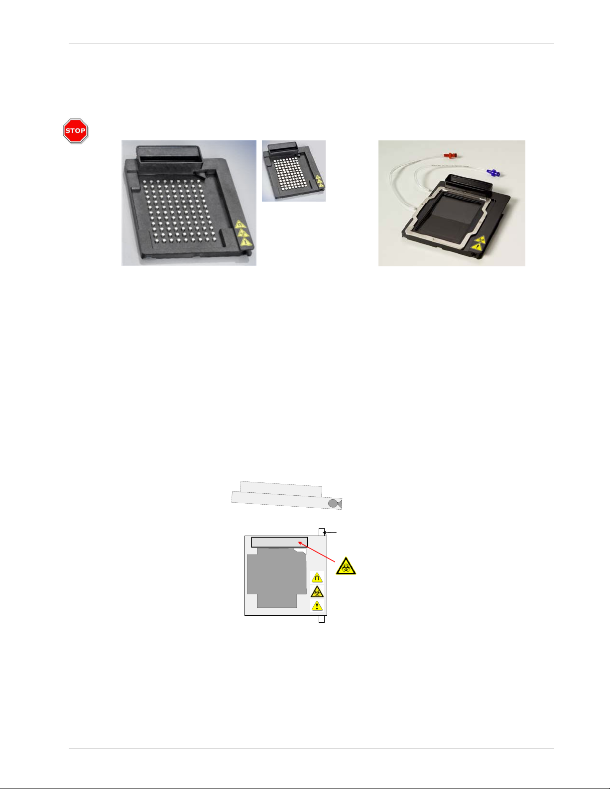
Attention!
Use only the type
of magnetic carrier
which arrived with
your instrument.
If your wash
station arrived with
version B use of
version A on your
wash station will
result in poor
assays results.
Version B is backcompatible with
previously installed
wash stations.
Magnetic Plate Carrier
(Version B)
(Version A)
Use magnetic plate carrier with: Use vacuum plate carrier with:
• Bio-Plex Pro assays • Bio-Plex assays (non magnetic)
Vacuum Plate Carrier
• Bio-Plex Precision Pro™ assays • Any assay on Bio-Plex COOH beads
• Any assay with MagPlex™
microspheres
Remove the standard ELISA plate.
1. Make sure the instrument is turned off.
2. Lift the manifold arm.
3. Slightly tilt the plate carrier towards the right.
4. Carefully slide the plate carrier toward the front of the instrument until it clears the guide bar.
Prime Tray
Guide Bar
Installing the plate carrier is the reverse of the procedure above:
• Any assay on MicroPlex
microspheres
1. Carefully guide the plate carrier onto the guide bar in a slightly tilted position, as shown
above.
2. Push the plate carrier completely into the instrument, so that the front of the carrier is even
with or past the Bio-Rad logo.
3. Lower the plate carrier.
4. Lower the manifold arm.
Bio-Plex Pro and Bio-Plex Pro II Wash Stations 17
Page 18

Basic Operation and Maintenance
Changing the Vacuum Configuration
You must set the vacuum system appropriately for the plate carrier used. This is
done through the VACUUM FILTR menu. Follow the procedure shown below to:
• Enable Low VAC when using the vacuum carrier
• Disable Low VAC when
1). using the magnetic carrier
2). using the standard ELISA plate carrier
Disabling/Enabling the Vacuum Carrier
Go through these menus to disable or enable the vacuum carrier. If you are disabling
the vacuum, the menus will display “Disable” in place of “Enable.”
SETTINGS
< > OK
Navigate to Settings in the Primary menu
and press OK
OPTIONS
- + EXIT OK
Select and press OK for OPTIONS
VACUUM FILTR.
- + EXIT OK
Select and press OK for VACUUM FILTR.
Enable Low VAC
EXIT YES
Enable vacuum carrier by choosing YES
(“Disable Low VAC” will be displayed if already enabled)
Enable Low VAC
System enables vacuum carrier
EDIT LLD CHANNEL
- + EXIT OK
System places you in the Options menu at EDIT
LLD CHANNEL. EXIT to Primary menu (press
EXIT until it is no longer an option)
PROGRAM
< > OK
The instrument must be turned off and then back on for the change to take effect.
Failure to set
Vacuum Filtration
settings
appropriately for the
installed plate
carrier will result in
a MANIFOLD HEAD
UP error. This
indicates that the
manifold arm cannot
lower appropriately.
18 Bio-Plex Pro and Bio-Plex Pro II Wash Stations
Page 19
Basic Operation and Maintenance
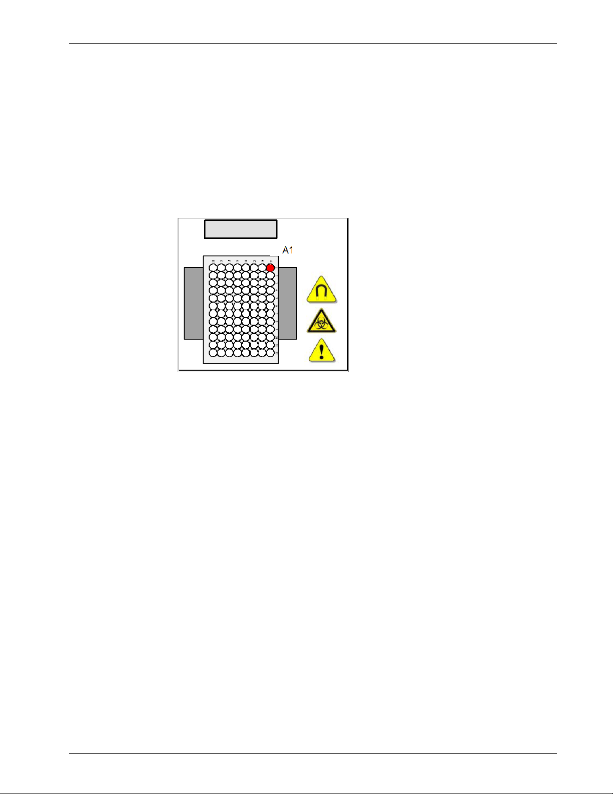
Installing the Microplate
Insert the 96-well microplate into the plate transport for washing and ensure that the
microplate is correctly oriented (position A1 of the plate corresponds to position A1
marked on the plate transport). If using the vacuum plate carrier for polystyrenebased assays, see Changing the Plate Carrier on page 23.
Turning on the Power
The power switch is located at the rear of the instrument, above the power cable
connection. Make sure the instrument is plugged in using the provided po wer cable
before you attempt to operate.
Bio-Plex Pro and Bio-Plex Pro II Wash Stations 19
Page 20
Basic Operation and Maintenance
F
Keypad Basics
All the functions you need to run Bio-Plex programs are easily accessed using the
keypad on your wash station. The system is organized into primary and secondary
menus.
Primary Menu
The instrument menu has the following options:
Primary
Options
Programs Wash programs used to process assays Start, Define/Edit, Show, Clear
Settings Rarely access ed advanced features Edit Plates, Options, Bubble Sensor
Procedures Preparation or maintenance processes Prime, Rinse, Empty Prime Tray,
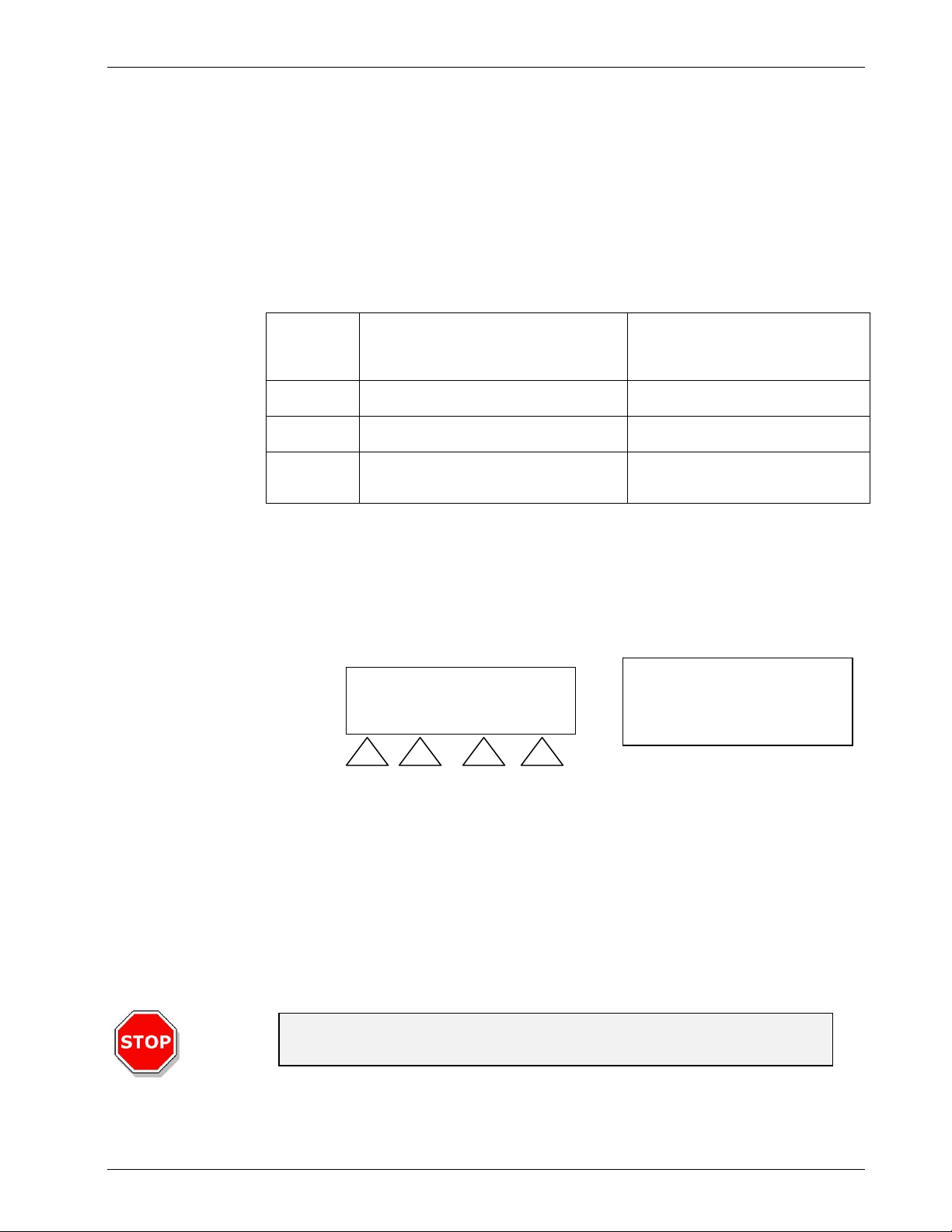
Secondary Menu
If you choose OK when any of the primary menu options (Programs, Settings, and
Procedures) are visible on the LED, you will navigate to the secondary menus. You
may Select a choice from the secondary menu, or press Exit to return to the primary
menu.
LCD
Keypad
buttons
Menu
Functions Secondary Menu Options
PROGRAM
< > OK
< >
Navigate
to other
options
Select or
Exit
Vacuum Filtration
If you get confused about
where you are, press Exit,
until you no longer see Exit
as an option.
Priming the Instrument
You should prime both Channel 1 and 2 after installation and if the instrument has not
been used for an extended period of time. Priming is performed to fill the liquid
system of the instrument and to remove all air from the tubes. A priming step must
also be performed when switching to a different wash buffer.
Caution
Do not use your new instrument until you have primed both channels.
20 Bio-Plex Pro and Bio-Plex Pro II Wash Stations
Page 21
Basic Operation and Maintenance
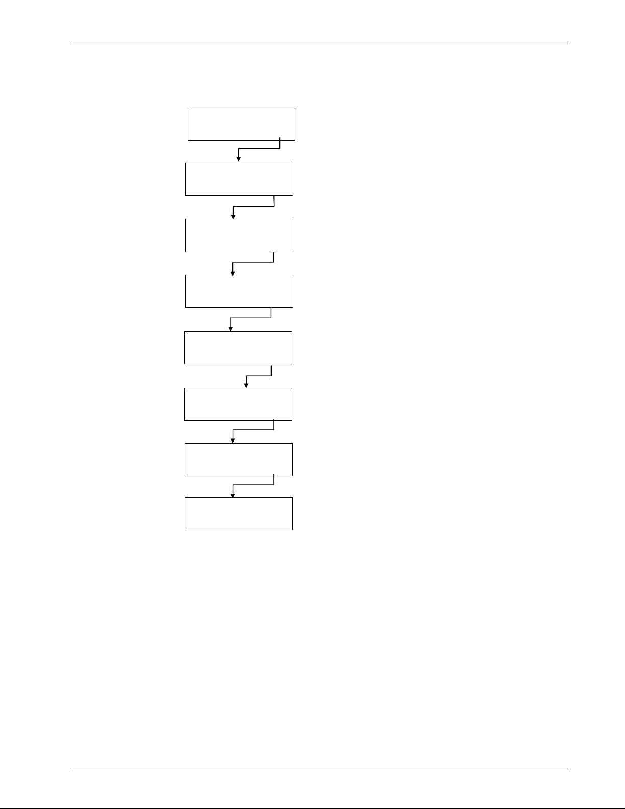
Perform priming for both channels using the following procedure:
PROCEDURE
< > OK
Navigate to the Procedure in the primary
menu and press OK
PRIME
PRIME
< > OK
< > OK
Select and press OK for PRIME
PRIME SOLUTION OK?
< > YE S
Confirm rinsing solution and tube in bottle
WASTE BOTTLE OK?
< > YES
Confirm waste bottle is connected and
sufficie nt ly e mp t y
VOLUME
< > OK
Press OK if you see VOLUME. If you see
TIME, scroll down to VOLUME, then press OK
VOLUM E 30 mL
+ - OK
Press OK
CHANNEL 1
- + EX I T OK
Select CHANNEL 1 using the choice keys (< , >)
Select OK and the prime procedure starts
PROGRAM
< > OK
Instrument will perform the prime step and will
then be ready to perform wash protocol s
Repeat for channel 2.
Failure to Prime
If you have a new instrument or it has not been used for a long time the pump may
fail to draw fluid from the liquid bottles. This problem is easily solved.
1. Disconnect the L1 tube from the bottle (leaving it connected to the
instrument).
2. Hold the free end of the tube high and pipette 3 - 4 ml of deionized
water to the tube while performing the prime procedure in channel 1
as described above.
Alternately you may carefully use a syringe to inject 1 - 2 ml of water directly into the
L1 port of the instrument, reconnect the tubing, and run a prime procedure.
Bio-Plex Pro and Bio-Plex Pro II Wash Stations 21
Page 22
Basic Operation and Maintenance
Plate Washing Programs
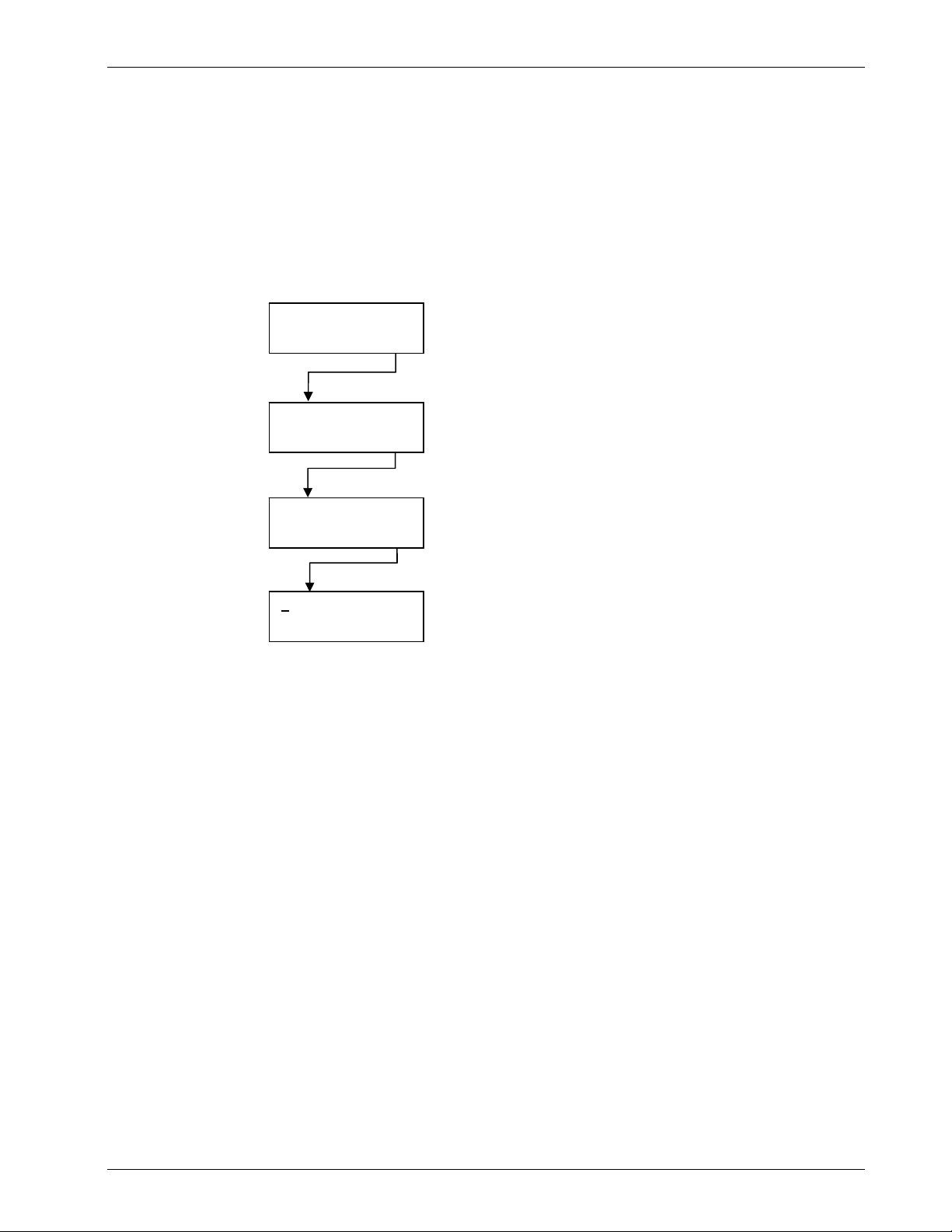
Instructions for running the preconfigured wash program are detailed below.
Instructions for setting new Wash, Dispense, and Aspirate modes into a new wash
program, and instrument rinse instructions, are found in the Defining New Programs
section on page 53.
PROGRAM
< > OK
START
< > OK
RUN1: Program X
< > EXIT OK
SSSSSSSSSSSS
+ - OK
Navigate to PROGRAM in the primary
menu and press OK.
Use the keys under the < and > symbols to access the
Program menu if it is not already displayed
Press OK
Select the required program and press
OK to continue
Choose OK.
Rows are represented by S (selected) or
N (not selected). All rows should be
selected.
It is highly recommended that all wells
are selected and the entire plate is
washed.
22 Bio-Plex Pro and Bio-Plex Pro II Wash Stations
Page 23
Basic Operation and Maintenance
A
A
y)
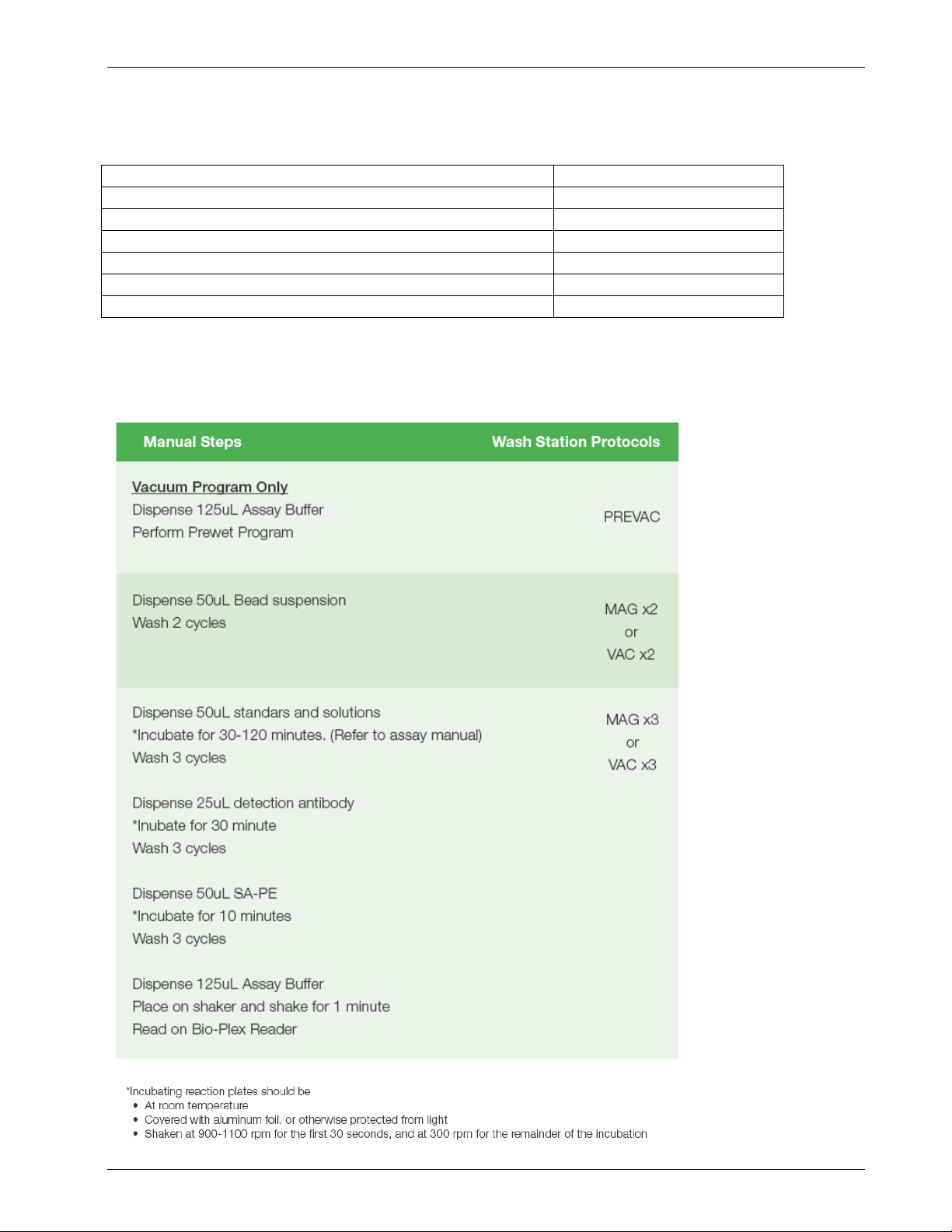
Which Wash Program Do I Use?
In this instance. Use Wash Station Program
First wash, magnetic assay
ll other washes, magnetic assay
Prewash, vacuum assay
First wash, vacuum assay
ll other washes, vacuum assay
Third party kits which require 200 µl washes (Vacuum onl
For all protocols, it is highly recommended that you wash the entire plate. See page 18 for details.
Quick Guide
MAG x2
MAG x3
PREVAC
VAC x2
VAC x3
V 200 x2 or V 200 x3
Bio-Plex Pro and Bio-Plex Pro II Wash Stations 23
Page 24
Basic Operation and Maintenance
Important Vacuum Protocol Precautions
• Carefully place the plate so that it is flat and squarely seated between the metal frames on the
vacuum carrier before stating a vacuum protocol
• It may be necessary to apply a small amount of pressure to the plate for the first vacuum cycle of the
day
• Monitor your plate periodically to ensure complete removal of wash buffer before the next dispense
cycle
• Blot the bottom of the filter plate on a paper towel within 5 seconds after each program is completed.
If you are not sure how much time has elapsed, run a PREVAC program to clear any residual buffer
that may have wicked back into the wells before proceeding to the next step
Vacuum protocols will not work if you do not have buffer in every well.
24 Bio-Plex Pro and Bio-Plex Pro II Wash Stations
Page 25
Basic Operation and Maintenance
Rinsing
The instrument should always be rinsed after use. Afterwards, the instrument can
either be left switched on, with the manifold in the rinsing solution, or switched off
after performing the correct maintenance.
Rinse Day
If the instrument will be left to stand for a short time (i.e. up to 2 hours), you may
perform Rinse Day with wash buffer so that you do not have to prime before the next
run.
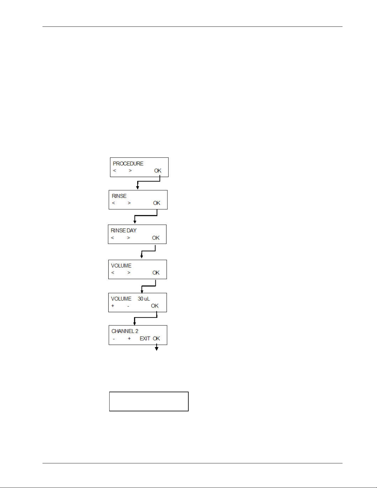
Perform Rinse Day by making these menu choices:
When the rinsing procedure is complete, the following message is displayed:
RINSE DAY
STOP END
The manifold remains in the prime tray until END is pressed.
Press STOP to abort the procedure (prime tray will not be aspirated).
Navigate to PROCEDURE in the primary
menu and press OK.
Use the keys under the < and > symbols to access the
PROCEDURE menu if it is not already displayed
Select and press OK for RINSE
Select and press OK for RINSE DAY
Press OK when presented with the option to the left
If presented with TIME you can use the default settings here as well. Or navigate to
VOLUME using < and > .
Press OK when presented with the option to the left
Or use the default time settings
Select CHANNEL 1 or 2 (using the choice keys <, >)
Remember to prime channel 1 before performing the next
wash protocol if you rinse with channel 2
Instrument will perform rinse procedure.
Bio-Plex Pro and Bio-Plex Pro II Wash Stations 25
Page 26

Basic Operation and Maintenance
Rinse Night
If the instrument will be left to stand for a longer period of time (such as overnight),
perform the Rinse Night procedure using these menu choices:
When the rinsing procedure is completed the following message is displayed:
RINSE NIGHT
STOP END
The manifold remains in the prime tray until END is pressed. Press STOP to abort
the procedure (prime tray will not be aspirated).
Navigate to PROCEDURE in the primary
menu and press OK.
Use the keys under the < and > symbols to access the
PROCEDURE menu if it is not already displayed
Select and press OK for RINSE
Select and press OK for RINSE NIGHT
Press OK when presented with the option to the left
If presented with TIME you can use the default settings here as well. Or navigate to
VOLUME using < and > .
Press OK when presented with the option to the left
Or use the default time settings
Select CHANNEL 2 (using the choice keys <, >)
At the end of the day always rinse with CHANNEL 2, distilled
O or equivalent.
H
2
Instrument will perform rinse procedure.
Instrument state at the end of the wash
Considerations for leaving the instrument on or off after a rinse procedure.
• Leave the instrument on if you want to soak the manifold overnight
(Recommended during periods of heavy use)
• Shut the instrument off if you do not wish to soak the manifold (Rinse Night
only)
26 Bio-Plex Pro and Bio-Plex Pro II Wash Stations
Page 27

Basic Operation and Maintenance
If the instrument will be switched off at the end of operation, the Rinse Night
procedure should be performed. This prevents the needles from becoming blocked.
Use the Rinse Night procedure to rinse the wash system as outlined above.
When the rinsing procedure is completed the following message is displayed:
RINSE NIGHT
STOP END
The manifold remains in the prime tray until END is pressed. Press STOP to abort
the procedure (prime tray will not be aspirated).
The most important cleaning procedure for this instrument is rinsing the
liquid system with distilled water at the end of each day.
Changing the Plate Carrier
See Page 16 for detailed instructions on selecting and replacing the plate carrier.
Bio-Plex Pro and Bio-Plex Pro II Wash Stations 27
Page 28

Basic Operation and Maintenance
Preventive Maintenance Plan
WARNING
All parts of the instrument that come into contact with potentially
infectious material must be treated as potentially infectious areas.
It is advisable to adhere to applicable safety precautions, (including the
wearing of powder-free gloves, safety glasses and protective clothing) to
avoid potential infectious disease contamination when performing
cleaning procedures and also when making adjustments to the
instrument.
WARNING
RISK OF FIRE AND EXPLOSION!
Prior to cleaning the outer surface of the instrument and the display,
switch off the instrument and disconnect it from the main power supply!
Daily
Weekly
• Prime the liquid system if necessary
• Perform Rinse Day with wash buffer, if the instrument is left to stand for a short
time (up to 2 hours). Use distilled water if you anticipate longer intervals
between uses
• Perform Rinse Night with distilled water at the end of a day of use
• If necessary (due to particles, soiling, etc.), prime the instrument several times
with distilled water
• If the instrument will be left to stand for a longer period of time (more than one
week), prime with distilled water and then prime without liquid
• Perform Rinse Night with distilled water and soak the manifold overnight (leave
instrument on)
• Prime the instrument without liquid to empty the entire liquid system.
(Reconnect the lines and prime with distilled water unless not using the
instrument for an extended period)
• Check the filter(s) in the liquid bottle(s) for particles and rinse liquid filter(s) with
distilled water
• Clean the plate carrier guide bar with 70% ethanol
28 Bio-Plex Pro and Bio-Plex Pro II Wash Stations
Page 29

Basic Operation and Maintenance
Every Six Months
• Clean the plate carrier guide bar with 70% ethanol
• Remove the magnetic plate carrier and check the spring-loaded centering
mechanism at the right rear of the carrier. If the mechanism does not move
freely, rinse thoroughly with 70% ethanol
• Clean aspiration and dispensing needles. Two kinds of cleani ng needles are
supplied with the instrument. Clean the manifold aspirating needles with the
smaller of the two. Clean the dispensing needles with the thicker cleaning
needles. Carefully raise the manifold arm and clean each instrument needle by
inserting the cleaning needle into the instrument needle and gently agitating, to
remove any possible debris. Then rinse with water
• If you choose to remove the manifold for cleaning refer to page 66 for
instructions
As Needed
To replace the plate carrier seal:
1. If the plate carrier seal becomes visibly damaged, remove the defective seal
and clean the plate carrier frame with ethanol, making sure no adhesive is left
2. Peel back the protective paper from the new seal and attach to the plate
carrier frame be careful not to block the ventilation hole
Note
Clean the aspirating and dispensing needles periodically or
immediately if they become clogged with particles or crystals.
Yearly (Service Engineer Required)
Yearly maintenance is performed by the service engineer.
Bio-Plex Pro and Bio-Plex Pro II Wash Stations 29
Page 30

About the Instrument
Reference Section
Purpose of reference section
Use this section of you have questions that are not answered in Basic
Operation and Maintenance.
The reference section is provided for customers interested in more detail about
the operation of the wash stations. Provided you follow standard safety
precautions this section is not required for normal operation.
There is some information in this section for troubleshooting and advanced
programming options.
30 Bio-Plex Pro and Bio-Plex Pro II Wash Stations
Page 31

About the Instrument
Instrument Details
Instrument Safety
Always follow basic safety precautions when using this product to reduce the risk of
injury, fire, or electrical shock.
Read and understand all information in the IFU. Failure to read, understand, and
follow the instructions may result in damage to the product, injury to operating
personnel, or poor instrument performance.
Observe all Warning and Caution notices (see Warnings, Cautions, and Notes on
page viii for a description of the notices used in this document).
Never open the Instrument while the instrument is plugged into a power source.
Observe proper laboratory safety precautions, such as wearing protective clothing
and using approved laboratory safety procedures.
Note
Suitable Compact Microplates
The instrument supports the processing of flat, round, or v-shaped bottom
microplates in 96-well format typically used for Enzyme Immunoassays (EIA),
which conform to the standard defined by the Society of Biomolecular
Screening. However it is recommended that you only use the recommended
plates for xMAP assays.
WARNING
Waste bottle – Liquid level
Make sure the liquid level of the waste bottle is always kept below the maximum
level indicated on the bottle, to avoid overflow. As the contents of the waste
bottle are potentially infectious, wear protective clothing (gloves, lab coat, and
safety glasses) when emptying / handling a waste bottle.
Inquire about appropriate collecting points and approved methods of disposal in
your country, state, or region.
Bio-Plex Pro and Bio-Plex Pro II Wash Stations 31
Page 32

About the Instrument
WARNING
When using wash buffers that show a strong tendency to foam, empty the waste
bottle as soon as the foam level has reached the maximum filling level indicated
on the waste bottle. Add a commercially available anti-foaming agent (such as
silicone oil) to the empty waste bottle to reduce foaming.
If foaming continues to be a problem, we recommend switching to a larger waste
bottle (not provided with the Instrument) and to increase the concentration of
anti-foaming agent in the waste bottle. To help facilitate breakdown of the foam
in the waste bottle, carefully swirl the waste bottle from time to time to improve
mixing between foam layer and anti-foaming agent.
Refill anti-foaming agent after emptying waste bottle. For example, when using
the Wacker Anti-Foam Emulsion SE47 (Wacker article code 21640582), the
recommended concentration is 1 ml of antifoaming agent for 1 liter of waste
solution.
Use antifoaming agents and concentrations as recommended by corresp onding
manufacturers.
Intended Use
The Bio-Plex Pro and Bio-Plex Pro II are instruments for strip-wise processing of
microplates in the 96-well format. The instrument is designed for professional use
only and should only be operated by trained personnel.
Caution
The wash results obtained with the Instrument are influenced by the
correct use of the instrument, according to the instructions given in this
document, as well as the liquid compounds used (reagents, wash buffer,
chemical components). The instructions for use, storage, and other
handling in connection with samples or reagents must be strictly
followed.
Caution
Before the instrument is installed and switched on, it should be left to
stand for at least three hours, so there is no possibility of condensation
causing a short circuit.
Caution
Before washing procedures are started, make sure that the microplate
32 Bio-Plex Pro and Bio-Plex Pro II Wash Stations
position A1 is inserted correctly.
Page 33

About the Instrument
The instrument is a general purpose laboratory instrument (Europe) and is a Class I
General Controls medical device (U.S.) for the processing of samples from biolo gical
and non-biological origin.
The wash stations are designed primarily for the processing of Bio-Plex and other
xMAP assays. The instruments may also be used for the processing of ELISA assays
and the washing of adherent cells.
Configurations
Both wash stations are delivered with the magnetic carrier installed and the
appropriate programs for performing the wash steps of magnetic bead based assays.
The Bio-Plex Pro II is also supplied with a vacuum manifold plate carrier to perform
wash steps for standard Bio-Plex assays and other non magnetic xMAP assays. In
order to do this, you must install the vacuum manifold plate carrier and connect the
appropriate tubing as indicated in Changing the Plate Carrier on page 23. You must
also redefine the configuration of the instrument using the keypad as outlined in
Complete Instrument Keypad Functions on page 43. Use the appropriate standard
programs.
Both instruments can also be used to process other plate-based assays. If you wish
to do so, you can leave the magnetic carrier in place. If you have concerns about the
magnetic fields affecting your assay, you can replace the magnetic plate carrier with
the standard plate carrier. Make sure you reconfigure the system as outlined in
Complete Instrument Keypad Functions on page 43.
Caution
Unauthorized modification of the instrument, any of its options and/or
components as well as on any corresponding software or spare parts
will result in a loss of warranty and a potential loss in instrument
performance.
Caution
It is important to understand that the proper installation of the
instrument and software alone will not ensure compliance with national,
regional, or local regulations. A range of policies and standard operating
procedures according to applicable regulations must additionally be
established.
Caution
Mandatory System Validation by Operating Authority
The instrument has been validated on representative Enzyme
Immunoassays (EIA) only in Europe. It is therefore the responsibility of
any Operating Authority to ensure that the instrument has been
validated according to applicable regulations for each specific assay
used on the instrument.
Bio-Plex Pro and Bio-Plex Pro II Wash Stations 33
Page 34

About the Instrument
Instrument Specifications
Note
Instrument specifications have been defined using Bio-Plex Pro flat
bottom microplates (Cat # 171025001), and may vary using other 96-well
PARAMETERS CHARACTERISTICS
plates.
The table below lists the specifications for the instrument. All specifications listed
below are based on the following instrument settings:
Dispense/Wash rate: 250 µl/s/well
Aspiration rate: 3
General
Display unit Liquid Crystal Display with 2 rows of 16 digits
Keyboard 4-key membrane keyboard
Number of dispensing
channels
Manifold types 8 channel manifold
USB Interface All connected devices must be approved and listed as per IEC 60950-1
Variable
Volume of solution
dispensed
Dispensing accuracy <= 2 %
Dispensing uniformity <= 4 % CV
Up to 4 channels
Information Technology Equipment – Safety or equivalent local standards.
50 - 3000 µl in 50 µl increments for washing
50 - 400 µl in 50 µl increments for dispensing
Measured under following conditions:
8-way manifold, 300 µl, dispensing rate 3 (250 µl/s/well), wash buffer, Bio-
Rad 96-well flat-bottom plates (Cat. # 171025001).
Measured under following conditions:
8-way manifold, 300 µl, dispensing rate 3 (250 µl/s/well), wash buffer, Bio-
Rad 96-well flat bottom plates (Cat. # 171025001).
Residual volume Measured under following conditions:
<= 4 µl / well, using Bio-Plex Pro flat-bottom plates and the recommended
preloaded programs. (Optimized for high bead recovery and low assay
%CVs.)
34 Bio-Plex Pro and Bio-Plex Pro II Wash Stations
Page 35

About the Instrument
PARAMETERS CHARACTERISTICS
Carry over
between wells
Vacuum Filtration
Vacuum range (BioPlex Pro II Only)
Power
Supply Auto-sensing
Consumption < 65 VA
Physical
Outside dimensions
(without Vacuum
Filtration)
Weight
(without Vacuum
Filtration)
<= 1 ppm
The carry over between wells <= 1 ppm cannot be guaranteed if not all wells
are filled with liquid.
-50 to -150 mBar absolute pressure
100 - 120 V or 220 - 240 V, 50/60 Hz
Width: 275 mm, Depth: 366 mm, Height: 180.5 mm
(Width: 10.8 in., Depth: 14.4 in., Height: 7.1 in.)
Greater depth and height in service position
6.6 kg
Environmental
Ambient temperature
Operation 15°C to 35°C (59°F to 95°F)
Storage -20°C to 60°C (-4°F to 140°F)
Relative Humidity
Operation 20 % to 80 % non-condensing
Storage 10 % to 80 % non-condensing
Others
Overvoltage category II
Pollution degree 2
Method of disposal Electronic waste
(infectious waste)
Bio-Plex Pro and Bio-Plex Pro II Wash Stations 35
Page 36

About the Instrument
r
Description
The diagram below shows the main components of the instrument:
Manifold Arm
power
Manifold
Prime Tray
Plate Support
Guide Ba
Keyboard and
Display Unit
Power ON
LED
Liquid System Diagram
36 Bio-Plex Pro and Bio-Plex Pro II Wash Stations
Page 37

About the Instrument
Bio-Plex Pro Dimensions
Bio-Plex Pro and Bio-Plex Pro II Wash Stations 37
Page 38

About the Instrument
Bio-Plex Pro II Dimensions
38 Bio-Plex Pro and Bio-Plex Pro II Wash Stations
Page 39

About the Instrument
Rear Panel Connections
The instrument has the following connections on the rear panel:
On/Off
Main Power Socket
Inlets for Liquid Channels 1 + 2
USB port
VAF
Vacuum Tubing
Ports (Bio-Plex Pro
II only)
Waste Tube
Instrument Name Plate
The instrument name plate is located under the main power socket. The company
information on the top differs, depending upon where it is purchased. The nameplate
also shows the model name, the model (part) number, and the serial number.
Use the provided power cord or a similarly-rated replacement cord only.
Bio-Plex Pro and Bio-Plex Pro II Wash Stations 39
Page 40

Detailed Operating Instructions
Detailed Installation
When installing, moving, or connecting the instrument, follow the instructions in this
publication. Bio-Rad® Laboratories does not accept the responsibility for injury
suffered by anyone attempting these operations without following the instructions in
this publication, nor for damage incurred to the instrument.
Make sure the laboratory meets all the requirements and conditions described in this
chapter.
Required Working Area
Select an instrument location that is flat, level, vibration free, away from direct
sunlight, and free from dust, solvents, and acid vapors.
Allow at least 10 cm (4 in.) between the instrument and the wall or any other
equipment. Do not place any items close to the instrument that could obstruct airflow.
Ideally the liquid bottles should be placed at the same level as the instrument and in
plain sight so they can be easily monitored for liquid level. They should not be placed
more than 1 m below the level of the instrument since this may result in instrument
malfunction.
For information regarding outer dimensions and weight of the instrument, see
the Instrument Specifications section on page 30.
Power Requirements
The instrument is designed to operate at either 100-120 V or 220-240 V.
No voltage setting is required as the instrument automatically senses the supplied
voltage.
Unpacking and Inspection Checklists
1. Visually inspect the container(s) for damage before opening.
2. Report any damage immediately.
3. Place the carton in an upright position and open it.
4. Lift the instrument out of the carton and place it in the selected location.
5. Remove the transport protection from the instrument and manifold.
6. Visually inspect the instrument for loose, bent, or broken parts. Report any
damage immediately.
7. Compare the serial number on the rear panel of the instrument with the serial
number on the packing slip. Report any discrepancy immediately.
8. Check the instrument accessories against the packing list. Save packing
materials for further transportation purposes. The instrument must be
returned in the original packaging.
40 Bio-Plex Pro and Bio-Plex Pro II Wash Stations
Page 41

Detailed Operating Instructions
The Bio-Plex Pro instrument is shipped in one carton, which contains the following
important components:
1. Standard plate carrier (installed in instrument)
2. Magnetic carrier
3. A small bag containing
a. USB cable
b. 2 cleaning needles
4. 2 liquid bottles (2.5 L) with lids
5. 1 waste bottle (5 L) with lid
6. Bundle of 2 tubes for connecting to the liquid bottles
(5mm outer diameter; 3mm inner diameter)
7. Main power cable
8. Instrument manual
9. CD with software and support material
10. 10 Bio-Plex Pro flat-bottom plates
The Bio-Plex Pro II is also shipped in one carton, and contains everything from the
above list, plus:
1. Located in the same small bag indicated in # 3 above. Not needed for Bio-Plex
Pro
a. Six small screws (two screws are required to attach the Bio-Plex Pro II
mounting bracket)
b. A Hex Tool.
2. A vacuum plate carrier
3. Vacuum tubing mounting bracket (see page 13)
Bio-Plex Pro and Bio-Plex Pro II Wash Stations 41
Page 42

Detailed Operating Instructions
Detailed Operating Instructions
Switching the Instrument On
Ensure the instrument has been correctly installed and the main power cable is
connected into the main power socket in the rear panel of the instrument and the
liquid tubes are connected to the correct liquid and waste bottle(s).
Switch ON the instrument, using the on/off switch in the rear panel of the instrument.
The initialization procedure is performed and, depending on the instrument type, the
following initialization message is displayed:
If a Rinse procedure was aborted before the instrument was switched off, the
following message is displayed after the instrument initializes:
Press OK and then select a Rinse procedure. (Rinse Day will work in all cases.) After
the rinsing procedure has been performed, the instrument proceeds to the standby
mode and the following message is displayed:
Caution
The liquid system must be primed before it can be used. Please ensure
that the dispensing and aspiration pumps are not run for longer than a
few minutes without liquid, otherwise they will be damaged.
Caution
At the end of each working day, perform the Rinse Night procedure with
42 Bio-Plex Pro and Bio-Plex Pro II Wash Stations
distilled water to ensure the proper performance of the instrument and
to prevent needles from becoming blocked.
Page 43

Detailed Operating Instructions
Complete Instrument Keypad Functions
The instrument keypad is used to run and manage wash programs, as well as
vacuum filtration programs, to define plate parameters, adjust certain instrument
settings, and perform instrument procedures (rinse, prime, and empty prime tray).
The following features are available:
• Preloaded programs for processing Bio-Plex and Bio-Plex Pro assays (also
appropriate for other standard and magnetic xMAP assays)
• 20 user definable washing programs, stored under program positions 1 to 20
• Up to 60 processing steps per program; each processing step can be identical or
different from the previous step
• Adjustable soak time (1 second to 60 minutes and 59 seconds)
• Variable shaking settings:
o High: Linear shaking with a shaking frequency of 25 Hz and a shaking
amplitude of 1 mm
o Medium: Linear shaking with a shaking frequency of 10 Hz and a
shaking amplitude of 2 mm
o Low: Linear shaking with a shaking frequency of 5 Hz and a shaking
amplitude of 3 mm
• Adjustable dispense rate (drip mode to 500 µl/s)
• Adjustable aspirating speed (1 to 3)
• Adjustable bottom positions (bottom, custom, overflow)
• Two rinse modes (Rinse Day and Rinse Night) can be used to select how the
instrument is rinsed before it is left to stand or switched off
• Automatic microplate centering, before starting any wash program
• Programmable strip selection, before starting the washing procedure
Bio-Plex Pro and Bio-Plex Pro II Wash Stations 43
Page 44

Page 45

Defining New Programs
Alphabetical list of LCD text with explanations
Bio-Plex Pro and Bio-Plex Pro II Wash Stations 45
Page 46

Defining New Programs
46 Bio-Plex Pro and Bio-Plex Pro II Wash Stations
Page 47

Defining New Programs
Bio-Plex Pro and Bio-Plex Pro II Wash Stations 47
Page 48

Defining New Programs
Defining Custom Wash Programs
The following instructions are for defining custom programs. The programs needed
for Bio-Plex or other xMAP assays are pre-installed on your wash station. No further
programs are needed unless your assay has unique needs. Access the pre-loaded
programs as described on pages 18 and 19.
The operating procedure is dependent on the instrument options and the program
settings.
Caution
Be careful that the plates are positioned in the microplate reader as
selected in the program, otherwise spilling can occur and the instrument
may become contaminated.
Wash Modes
WARNING
When the instrument is busy, do not touch the manifold!
After the instrument has been used, the manifold and prime
tray may be infectious!
The instrument can wash a microplate using the following wash modes:
Plate Mode
Strip Mode
Each program step is performed on all of the selected strips of a
microplate sequentially, before proceeding to the next step.
The entire plate or the defined plate range is processed for the
defined soaking time.
The entire wash program is performed on one strip of a
microplate before proceeding to the next strip. The strip is
processed for the defined soaking time, before proceeding to
the next strip or group of strips.
48 Bio-Plex Pro and Bio-Plex Pro II Wash Stations
Page 49

Defining New Programs
Washing Positions
Wash, dispense, and aspirate steps can be defined in a wash program with the
following Z-positions:
Overflow
Bottom
Custom
Move Overflow
Move Custom
Z-Position Bottom
For ELISA assays and cellular assays. Overflow washing consists of a
simultaneous aspiration and dispense step. It creates a circular flow of wash
buffer in the well and ensures that the topmost parts of the well are also
washed.
For ELISA assays.
Any necessary washing position can be selected; the custom positions are not
saved as *.pdf files in comparison to the overflow and bottom position.
If Move Overflow (MOVE OVER) is selected, the manifold moves step-wise
from the bottom position to the Overflow position during dispensing. It is
recommended for cell wash applications or any applications which must be
treated with care.
If Move Custom (MOVE CUST.) is selected, the manifold moves step-wise
from the bottom position to the user-defined Custom Z- position during
dispensing. It is recommended for cell wash applications or any applications
which must be treated with care.
Z-Position Custom
Z-Position Overflow
Overflow Position
Bottom Position
Wash Position Diagrams
MOVE OVER.
Movement of
manifold
Custom Position
Bottom Position
Movement Diagrams for Z-positions with MOVE
MOVE CUST.
Movement of
manifold
Bio-Plex Pro and Bio-Plex Pro II Wash Stations 49
Page 50

Defining New Programs
A
A
Aspirating Modes
To improve wash efficiency and reduce the residual volume, the manifold must be
positioned so that the aspirating needles are correctly positioned in the wells for
round-bottom, V-shaped bottom, or flat-bottom well microplates.
Normal AspirationMode
For round-bottom or V-shaped bottom wells, the aspirating needles are placed in the
middle of the wells. Only one aspiration position can be selected.
Round Bottom Wells
'V' Shaped Wells
Normal Aspirating Positions
Crosswise Aspiration Mode
With flat bottom wells, the instrument can perform crosswise aspiration using two
aspiration positions per well.
The aspirating needles are set at two positions on the bottom of the wells
(front edge and back edge).
spirate Y Offset 1
Front edge Back edge
Crosswise Aspiration for Flat Bottom Wells
spirate Y Offset 2
50 Bio-Plex Pro and Bio-Plex Pro II Wash Stations
Page 51

Defining New Programs
Drip Mode
The slowest dispensing mode is the drip mode. This mode is not recommended for
xMap or Bio-Plex applications.
Drip mode is used for very sensitive applications, e.g. washing cell layers, because
the instrument offers the possibility to dispense liquid in small drops. This minimizes
the detachment of cells and increases the remaining cell percentage at the bottom of
the wells.
The following example shows a typical wash program for working with adheren t cells
as it would appear in the Define/Edit menu. See Define/Edit a Program on page 49
for further information about defining programs.
Note
The following example program should not be used as a standard wash
procedure for cell washing as it is necessary to adjust the wash
parameters, such as Z-position “MOVE CUST.”, dispensing and aspirating
rates, head speed, etc., according to the cell type used.
Bio-Plex Pro and Bio-Plex Pro II Wash Stations 51
Page 52

Defining New Programs
DEFINE EDIT
< > EXIT OK
To define a program press OK to enter the DEFINE EDIT
menu.
PROGR 1:
- + EXIT OK
NAME:CELLWASH
567890, , ABCDE
PLATE MODE
- + EXIT OK
PLATE 1, GRE96ft
- + EXIT OK
NO. OF CYCLES 2
- + EXIT OK
C1 P1 WASH
- + EXIT OK
POS: MOVE CUST.
- + EXIT OK
Z-User Def 7000
- + EXIT OK
Select an appropriate position for the program.
Select an appropriate name for the program.
Select PLATE MODE and press OK.
Select an appropriate plate type and press OK.
Select 2 cycles and press OK.
Select WASH and press OK.
Select MOVE CUST. and press OK to continue to the next
parame ter
Set the user defined Z-position to the appropriate height and
press OK to continue to the ne x t pa ra meter
VOLUM E 450µl
- + EXIT OK
CHANNEL 1
- + EXIT OK
H-SPEED 1mm/s
- + EXIT OK
FLOWRATE DRIP
- + EXIT OK
PROGRAM END?
- + EXIT OK
FINAL ASP
- NO YES
Set the volume to 450 µl and press OK to continue to t he next
parame ter
set the channel to 1 and press OK to continue to the next
parame ter
Set the head speed to 1 mm/s and press OK to continue to the
next parameter
Set the flow rate to DRIP and press OK to continue to the ne xt
parameter
Select PROGRAM END? and press OK.
When the final aspiration step appears, press NO to finish
defining the program.
Example of a typical wash program for working with adherent cells
52 Bio-Plex Pro and Bio-Plex Pro II Wash Stations
Page 53

Defining New Programs
Defining New Programs
Introduction
The following program items are available:
CYCLE:
ASP:
DISP:
WASH:
SOAK:
VAC:
USER PROMPT:
FINAL ASPIRATE:
END PROGRAM:
Program Menu
The number of cycles the subsequent processing steps
should be performed
An aspirate step removes liquid from the wells
A dispense step fills the wells with liquid
Liquid is dispensed and aspirated simultaneously
creating a circular flow with a maximum volume of 3000
µl in one wash step for increased wash efficiency
During a soak step the liquid remains in the wells for the
set time (with or without shaking)
For collecting desired substances by vacuum filtration
using filtration plates
User interaction is requested
An aspirate step at the end of a program
The program finishes
The Program menu has the following options:
Start
Define/Edit
Show
Clear
The Program menu has the following structure:
PROGRAM
< > OK
START
< > EXIT OK
Bio-Plex Pro and Bio-Plex Pro II Wash Stations 53
DEFINE EDIT
< > EXIT OK
Run a defined wash program
Define or edit a program on the instrument
View the parameters of a defined program
Clear a wash program from the instrument’s menu
SHOW
< > EXIT OK
CLEAR
< > EXIT OK
Page 54

Defining New Programs
A
Define/Edit a Program
DEFINE EDIT
< > EXIT OK
Press OK to defin e or edi t a pr ogr am on th e instrument.
PROG1:
- + EXIT OK
NAME:EXAMPLE
567890, , ABCDE
PLATE MODE
- + EXIT OK
Plate 1, GRE96ft
- + EXIT OK
NO. OF CYCLES 1
- + EXIT OK
C1 P1 ASP
- + EXIT OK
Press - or + to select a program position in which a new
program will be defi n ed or s elec t an already exis t in g
program t o edit
Enter the required name for the program (up to eight
characters). Select a character by mo ving it with the cursor
keys between the commas and pressing the return key
Select , to delete a character. Select and press the
return key to save the program name and continue to
mode selection
Press - or + to select between plate or strip mode
Press - or + to select oth er pl at e typ es
Press - or + to select the number of cycles
(cycles can be repeated up to 9 times)
Press - or + to select the process step (ASP, DISP, WASH,
SOAK, PROGRAM END, CX CYCLE, where X is the
number of the next cycle). Press OK to define the selected
process step. Once the process step has been defined the
displ ay appears with th e st ep p osit i on inc remented (e.g. P1
becomes P2)
C1 P2 ASP
- + EXIT OK
C2 CYCLE
- + EXIT OK
PROGRAM END?
- + EXIT OK
FINAL ASP?
NO YES
START
< > EXIT OK
Select - or + to define the next process step
Press OK to define the selected process step
To add another cycle, press + until CX CYCLE is displayed
(X is the number of the next cycle). Press OK to define the
number of cycles.
Press – or + and press OK to select PROGRAM END
to finish defining the program.
dd a final aspiration step if necessary.
The parameters for the final aspirate step can be selected.
Once the program has been defined,
the Start men u app e ars ag ain.
54 Bio-Plex Pro and Bio-Plex Pro II Wash Stations
Page 55

Defining New Programs
A
Process Step: Aspirate
CX PX ASP
- + EXIT OK
Crossw.Asp YES
- + EXIT OK
POS: BOTTOM
- + EXIT OK
TIME: 4 s
- + EXIT OK
H-SPEED10mm/s
- + EXIT OK
ASP.RATE 2
- + EXIT OK
Select and confirm aspirating step (ASP)
CX = Cycle Number
PX = Program Step Number
Select YES using – or + to perform crosswise
aspiration or select NO to perform normal aspiration.
Press – or + to select the aspiration position
(BOTTOM; OVERFLOW or CUSTOM).
Select required aspirating time (1 - 20 seconds).
Select required aspirating speed (1 - 20 mm/sec).
Select required aspirating rate (1 - 3),
where 1 is the weakest and 3 the strongest rate.
CX PY ASP
- + EXIT OK
fter the process step has been defined the initial
display appears.
CX = Cycle Number
PY = Program Step Number incremented by 1
Press OK to define another aspiration step
or press – or + to select the next program step,
Program End or a new cycle.
Note
Low residual volumes cannot be guaranteed if not all wells in a strip are
filled with liquid. To prevent cross contamination, the head speed
should be lowered.
Bio-Plex Pro and Bio-Plex Pro II Wash Stations 55
Page 56

Defining New Programs
A
Aspiration Position Diagrams
Position Bottom
Aspiration Position Diagrams
Process Step: Dispense
CX PX DISP
- + EXIT OK
Position Custom
Select and confirm dispensing step (DISP)
CX = Cycle Number
PX = Program Step Number
Position Overflow
Z-POS: OVERFLOW
- + EXIT OK
VOLUME 300µl
- + EXIT OK
CHANNEL 1
- + EXIT OK
FL.RATE 300 µl/s
- + EXIT OK
CX PY DISP
- + EXIT OK
Select required dispensing position
(OVERFLOW, CUSTOM, MOVE OVER.,
MOVE CUST. or BOTTOM).
Select the volume of solution to be used
(50 - 400 µl in increments of 50 µl).
Select the channel to be used (1 - 4)
depending on instrument configuration.
Select required flow rate (drip to 500µl/sec ).
fter the process step has been defined the initial
display appears.
CX = Cycle Number
PY = Program Step Number incremented by 1
Press OK to define another dispense step
or press – or + to select the next program step,
Program End or a new cycle.
56 Bio-Plex Pro and Bio-Plex Pro II Wash Stations
Page 57

Defining New Programs
Dispensing Position Diagrams
Z-Position Bottom
Overflow Position
Bottom Position
Z-Position Custom
Position Diagrams
MOVE OVER.
Movement of
manifold
Custom Position
Bottom Position
Movement Diagrams for Z-positions with MOVE
Z-Position Overflow
MOVE CUST.
Movement of
manifold
Bio-Plex Pro and Bio-Plex Pro II Wash Stations 57
Page 58

Defining New Programs
A
Process Step: Wash
This process step is used to aspirate solution out of the wells and simultaneously
dispense and aspirate the solution.
CX PX WASH
- + EXIT OK
Select and confirm wash step (WASH)
CX = Cycle N umber
PX = Progr am Step Number
CROSSW. ASP. NO
- + EXIT OK
POS: OVERFLOW
- + EXIT OK
VOLUME 30 0µl
- + EXIT OK
CHANNEL 1
- + EXIT OK
H-SPEED 10 mm/s
- + EXIT OK
FL.RATE 200 µl/s
- + EXIT OK
Select Yes using – or + to perform aspiration of
wash cr ossw ise o r select No to perform normal
aspiration.
Select required dispensing position
(OVERFLOW, CUSTOM, MOVE OVER., MOVE
CUST. or BOTTOM).
Select the volume of solution to be used
(50 - 3000 µl in increments of 50 µl)
Select the channel to be used (1 - 4)
depending on instrument configuration.
Select required aspirating speed (1 - 20 mm/sec).
Select required flow rate (drip to 500µl/sec).
ASP. RATE 2
- + EXIT OK
TIME 1 s
- + EXIT OK
CX PY WASH
- + EXIT OK
Select required aspirating rate (1 – 3).
Select required aspirating time (1 – 20 mm/s).
fter the process step has been defined the initial
display appears.
CX = Cycle N umber
PY = Program Step Number incremented by 1
Press OK to define another wash step
or press – or + to select the next program step,
Program End or a new cycle.
58 Bio-Plex Pro and Bio-Plex Pro II Wash Stations
Page 59

Defining New Programs
A
A
Process Step: Soak
CX PX SOAK
- + EXIT OK
TIME: 0 min 10 s
- + Chg. OK
SHAKE OFF
- + EXIT OK
CX PY SOAK
- + EXIT OK
Process Step: User Prompt
CX PX USER PR.
- + EXIT OK
Select and confirm soak step (SOAK).
CX = Cycle Number
PX = Program Step Number
Select required soaking time using -/+ keys
(0 – 60 min; 1 - 59 seconds )
Press Chg. to select minutes or seconds.
The shaking speed can be selected
(OFF, LOW, MEDIUM or HIGH).
fter the process step has been defined the initial
display appears.
CX = Cycle Number
PY = Program Step Number incremented by 1
Press OK to define another soak step
or press – or + to select the next program step,
Program End or a new cycle.
Select and confirm User Prompt strip on
required position in current program.
Process Step: Vacuum Filtration
CX PX VAC
- + EXIT OK
VAC. -100.0 mBar
- + EXIT OK
TIME: 0 min 10 s
- + Chg. OK
CX PX ASP
- + EXIT OK
Select and confirm Vacuum Filtration step (VAC).
CX = Cycle Number
PX = Program Step Number
Select required vacuum pressure using the - /+ keys.
Select required soaking time using the - /+ keys
(0 – 60 min; 1 - 59 seconds )
Press Chg. to select minutes or seconds.
fter the process step has been defined the initial
display appears.
CX = Cycle Number
PY = Program Step Number incremented by 1
Press OK to define another vacuum filtration step
or press – or + to select the next program step,
Program End or a new cycle.
Bio-Plex Pro and Bio-Plex Pro II Wash Stations 59
Page 60

Defining New Programs
Note-Adjust parameters for filtration plates only when vacuum filtration
is enabled!
Show Program
This submenu is used to display the parameters that have been defined for a
program. An example wash program containing one cycle, one wash step, and a final
aspiration step will be used to demonstrate this menu.
The displayed parameter settings cannot be altered in this submenu.
SHOW
< > EXIT OK
Press OK to enter the Show menu.
PROG1: EXAMPLE
- + EXIT OK
STRIP MODE
EXIT OK
1: GRE96ft
EXIT OK
C1 CYCLE
- + EXIT OK
C1 P1 WASH
- + EXIT OK
POS: OVERFLOW
EXIT OK
VOLUME 300µl
EXIT OK
CHANNEL 1
EXIT OK
Select required program to show.
Press + or – to select programs from other positions.
Selected mode is displayed.
Selected plate type displayed
Cycle 1 will be shown.
Press + to show the program steps of this cycle.
Press OK to show the cycle number.
Press OK to show the parameters of the program step.
Press + to continue to the next program step;
Press “- “ to return to the previous step.
Press OK to continue to the next parameter
of the selected program step.
Press OK to continue to the next parameter
of the selected program step.
Press OK to continue to the next parameter
of the selected program step.
H-SPEED 10mm/s
EXIT OK
FL.RATE 300µl/s
EXIT OK
C1 P1 WASH
- + EXIT OK
FIN.ASPIRATE
- END OK
Press OK to continue to the next parameter
of the selected program step.
Press OK to continue to the next parameter
of the selected program step.
Once all parameters of the step have been shown the selected
Program Step appears again. Press + to continue to the next
program step; Press “- “ to return to the previous step.
Press OK to show the parameters of the final aspiration
step. If no final aspirate step was used, “CX CYCLEEND”
appears. Press OK to view the cycle number.
Press END to exit the Show menu. Press - to return to the
previous step.
60 Bio-Plex Pro and Bio-Plex Pro II Wash Stations
Page 61

Defining New Programs
Clear Program
This submenu is used to clear a program from the instrument's memory.
CLEAR
< > EXIT OK
Press OK to ent er the CLEAR
menu.
CLR PR OGR 1: A
< > EXIT OK
CLR P ROGR 1?
NO YES
A: DELETED
If the program is locked it cannot be cleared and the following message is displayed:
PROGRAM IS
LOCKED
The program can only be unlocked via the HydroControl software, by users with the
appropriate rights.
Settings Menu
The Settings menu has the following options:
Edit Plates
Select the program to be deleted
from the instrument's me mory
(Program Position: Program Name)
Confirm that se lected program
is to be deleted
CLR (Pro gram Position)?
The name of the program which
has been deleted appe ars
(Program Name: DELETED)
Adjustment procedure for setting the parameters for up to
20 different microplates.
Options
The Settings menu contains the following submenus:
Edit LLD Channels, Vacuum Filtration, Process Control.
Bubble
Sensor
The Bubble Sensor sensitivity can be set to Low, Medium, or
High depending on liquids used (if this option is installed). If very
foamy liquids are used the bubble sensor should be switched OFF.
The Settings menu has the following structure:
SETTINGS
< > OK
EDIT PLATES
< > EXIT OK
OPTIONS
< > EXIT OK
BUBBLE SENSOR
< > EXIT OK
Bio-Plex Pro and Bio-Plex Pro II Wash Stations 61
Page 62

Defining New Programs
Edit Plates
Predefined Bio-Plex plate definitions should not be edited!
EDIT PLATES
- + EXIT OK
Press OK to continue.
Plate 1, GRE96ft
- + EXIT OK
OVERFLOW POS.
< > EXIT OK
Z-User Def 14600
- + EXIT OK
EDIT PLATES
- + EXIT OK
Options Submenu
The Options submenu has the following structure:
Press – or + to select the plate (1-20)
and press OK to edit the plate parameters.
Use the cursor keys to select the position to be defined
(OVERFLOW, BOTTOM, ASP1 or ASP2) and press OK.
For round and V-shaped bo ttom plates,
only one aspiration can be defined.
The instrument moves to the predefined position.
Use the – and + keys to change the position. Confirm with OK.
The next position can then be selected.
Press OK to save the defined position; Press EXIT to leave the
menu without saving the position. The instrument moves to the
home position and the firmware returns to the Edit Plates menu.
OPTIONS
< > OK
EDIT LLD CHANNEL
- + EXIT OK
VACUUMFILTRATION
- + EXIT OK
PROCESS CONTROL
- + EXIT OK
Vacuum Filtration
See Page 18. Enabling/Disabling Vacuum.
Note
Make sure that the vacuum transport is mounted when the vacuum
62 Bio-Plex Pro and Bio-Plex Pro II Wash Stations
filtration option is enabled.
Page 63

Defining New Programs
Bubble Sensor
It is recommended that the Bubble Sensor be left off.
BUBBLE SENSOR
- + EXIT OK
Press OK to continue.
BUBBLE OFF
- + EXIT OK
Procedures Menu
The Procedures menu has the following options:
Rinse
Prime
Empty Prime Tray
Vacuum Filtration
The Procedures menu has the following structure:
PROCEDURES
< > OK
Press – or + to select between
OFF, LOW, MEDIUM and HIGH.
Press OK to confirm.
Start rinse procedures.
Start prime procedures.
Aspirate liquid out of the prime tray.
Prepare the vacuum pressure to prevent
delays during the running of a wash program.
RINSE
< > EXIT OK
PRIME
< > EXIT OK
EMPTY PRIME TRAY
< > EXIT OK
VACUUM FILTRATION
< > EXIT OK
Rinse
For details, see the Rinse section on page 24.
Prime
For details, see Priming the Instrument on page 20.
Empty Prime Tray
Navigate to empty EMPTY PRIME TRAY in the Procedures and Press OK. The
prime tray will be aspirated.
Bio-Plex Pro and Bio-Plex Pro II Wash Stations 63
Page 64

Page 65

Troubleshooting and Error Messages
Maintenance and Cleaning
Cleaning Procedures
WARNING
All parts of the instrument that come into contact with potentially
infectious material must be treated as potentially infectious areas.
The most important cleaning procedure for this instrument is to rinse the liquid system with distilled
water before the instrument is left to stand, or switched off at the end of each day.
The manifold should be removed and cleaned thoroughly at least once every six months, or
whenever one or more of the needles are blocked.
It is advisable to adhere to applicable safety precautions, (including the
wearing of powder-free gloves, safety glasses and protective clothing) to
avoid potential infectious disease contamination when performing
cleaning procedures and also when making adjustments to the
instrument.
Cleaning the Cover and Display
The outer surface of the instrument and the display may be cleaned periodically
using a tissue moistened with a mild detergent solution.
Caution
Never use acetone, as it will damage the covers.
Cleaning the Liquid System
To clean the liquid system, perform Rinse and Prime procedures as described in the
Basic Operation and Maintenance section.
Caution
If the manifold is not rinsed, the needles will become blocked.
Bio-Plex Pro and Bio-Plex Pro II Wash Stations 65
If this occurs, the manifold will need expensive repairs or will have to be
replaced.
Page 66

Troubleshooting and Error Messages
Cleaning the Manifold
The manifold can be cleaned using:
• The supplied cleaning needles (accessory box). The small cleaning needle is for
the dispensing needles, and the large cleaning needle is for the aspirating
needles. Carefully push the cleaning needles into the aspirating and dispensing
needles. Rinse the manifold block with distilled water to ensure that all particles
have been removed.
• A gentle ultrasonic bath of warm distilled water for 15 minutes
(max. five times, manifold must be removed from the instrument).
• Autoclaving (max. 130°C, max. five times, manifold must be removed from the
instrument.)
Do not autoclave manifolds with the Process Control option!
• Reinstall the manifold if necessary (see page 66).
• After the manifold has been cleaned, switch the instrument on and perform the
priming procedure using distilled water.
Cleaning Waste Bottles
Before cleaning the waste bottles, empty the bottles according to local disposal
regulations.
The bottles must be cleaned regularly depending on the applications, using a mild
detergent.
WARNING
When handling waste bottles, it is advisable to adhere to applicable
safety precautions (including wearing powder-free gloves, safety
glasses, and protective clothing) to avoid potential infectious disease
contamination.
66 Bio-Plex Pro and Bio-Plex Pro II Wash Stations
Page 67

Troubleshooting and Error Messages
Liquid or Foam Spills
WARNING
Always switch off the instrument before removing any kind of spills on
the Instrument.
All spills (liquid or foam) must be treated as potentially infectious.
Therefore, always adhere to applicable safety precautions, (ncluding
wearing powder-free gloves, safety glasses and protective clothing) to
avoid potential infectious disease contamination.
Additionally, all resulting waste from the clean-up must be treated as
potentially infectious and the disposal must be performed according to
local regulations.
If the spill occurs in the instrument, a service technician is required.
Spilling of liquid or foam may occur when the Instrument is operated improperly, such
as:
• Microplate used does not match installed manifold.
• The strip plate positions do not match the positions defined in the program used
for processing.
• Plate parameters are not properly adjusted.
• Waste bottle not emptied when liquid level or foam level reaches maximum filling
level.
• No anti-foaming agent used with wash buffers showing strong tendency to foam.
• Always remove spills immediately after they have occurred. Use paper tissue to
soak-up spills and wipe surface dry.
WARNING
WASTE BOTTLE - LIQUID LEVEL
Bio-Plex Pro and Bio-Plex Pro II Wash Stations 67
Make sure that the liquid level of the waste bottle is always kept below
the maximum level indicated on the bottle to avoid potential overflow.
The contents of waste bottle are potentially infectious, so it is important
to wear protective clothing (gloves, lab coat, and safety glasses) when
emptying OR handling a waste bottle.
Page 68

Troubleshooting and Error Messages
Replacing the Manifold
The Instrument is delivered with the manifold already installed. The manifold drawing
below shows the basic components.
Locating Pin
The Rear of the Manifold
Dispensing Tubes
Locating Pin
Aspirating Tubes
Note
Always wear powder-free gloves when handling the manifold.
WARNING
After the instrument has been used, the manifold may be infectious!
Before the manifold is removed it must be thoroughly disinfected.
It is advisable to adhere to applicable safety precautions, (including the
wearing of powder-free gloves, safety glasses, and protective clothing)
to avoid potential infectious disease contamination.
WARNING
Prime the instrument without liquid to empty all liquid from the system,
before removing the manifold.
68 Bio-Plex Pro and Bio-Plex Pro II Wash Stations
Page 69

Troubleshooting and Error Messages
Removing the Manifold
WARNING
Prime without liquid to remove liquids from the tubing system.
The manifold should be removed and thoroughly cleaned at least once every
6 months or whenever needles become blocked.
1. Lift the manifold arm and remove the black manifold arm guard plate by
removing the three screws using the Allen key provided.
3 screws
2. Lift the manifold arm and remove the two screws that attach the manifold to
the instrument using the Allen key provided.
2 screws
3. Carefully pull the tubing off the connectors on the rear of the manifold and
remove the manifold.
Bio-Plex Pro and Bio-Plex Pro II Wash Stations 69
Page 70

Troubleshooting and Error Messages
Installing the Manifold
The standard manifolds are installed using the following procedure:
1. Lift the manifold arm.
2. Carefully fit the manifold onto the manifold arm and ensure that the locating
pins are correctly inserted through the holes in the bracket.
Locating Pin Locating Pin
2 screws
3. Tighten the manifold into place using the two screws using the Allen key
provided.
4. Fit the dispensing tubes (marked blue) onto the top connector on the rear of
the manifold.
5. Fit the aspirating tubes (marked red) onto the two bottom connectors on the
rear of the manifold (marked with red labels).
6. Attach the black manifold guard plate with the 3 screws using the Allen key
provided.
3 screws
7. Lower the manifold arm and prime the instrument before starting a wash
program.
70 Bio-Plex Pro and Bio-Plex Pro II Wash Stations
Page 71

Troubleshooting and Error Messages
Instrument Disinfection
WARNING
The disinfection procedure should be performed according to national,
regional, and local regulations.
WARNING
All parts of the instrument that come into contact with potentially
infectious material must be treated as potentially infectious.
It is advisable to adhere to applicable safety precautions, (including the
wearing of powder-free gloves, safety glasses, and protective clothing)
to avoid potential infectious disease contamination when performing the
disinfection procedure.
It is very important that the instrument is thoroughly disinfected before it is removed
from the laboratory or any servicing is performed on it.
Before the instrument is returned to the service center for service or repair, it must be
disinfected and a disinfection certificate completed by the operating authority. If a
disinfection certificate is not supplied, the instrument may not be accepted by the
service center or it may be held by the customs authorities.
Disinfection Solutions
Use the following disinfection solutions for the disinfection procedure:
• Decon 90 (Decon Laboratories Limited)
• Decon Neutracon (Decon Laboratories Limited)
• Microcide SQ (Global Biotechnologies)
• Ethanol
WARNING
Bio-Plex Pro and Bio-Plex Pro II Wash Stations 71
Risk of fire and explosion!
Ethanol is flammable and when improperly handled can lead to
explosions. Proper laboratory safety precautions must be observed.
Page 72

Troubleshooting and Error Messages
Disinfection Procedure
The instrument should be disinfected using one of the solutions mentioned
previously.
Risk of fire and explosion!
Prior to cleaning the outer surface of the instrument and the display,
switch off the instrument and disconnect it from the main power supply!
Caution
Before starting the disinfection procedure use a rinse procedure (Rinse
Day) with distilled or deionized water (lab quality) to flush the system.
WARNING
WARNING
The disinfection procedure should be performed in a well-ventilated
room by authorized trained personnel wearing disposable powder-free
gloves, protective glasses and protective clothing.
Please note that the disinfectant can influence the performance of your instrument, if
it comes into contact with the electronics! Wear protective powder-free gloves,
protective glasses, and protective clothing.
The following procedure should be used to disinfect the instrument:
1. Prepare an autoclave bag for all disposables used during the disinfection
procedure, label it with autoclave tape and disinfect the material using the
autoclave, or follow the local regulations for decontamination of this material.
2. Prime the liquid system with disinfectant. Perform the Rinse Night procedure
with disinfectant solution and stop the procedure after five hours.
3. Switch off the instrument and disconnect the instrument from the power
supply.
4. Disconnect the instrument from any accessories that are used, for example:
Liquid Level Detection System, computer, etc. Accessories that should be
shipped together with the instrument have to be included in the disinfection
procedure.
5. Carefully spray the disinfectant solution on all outer instrument surfaces, or
wipe with a disposable soft tissue paper towel soaked in the disinfectant.
6. After a minimum contact time of 10 minutes, repeat step 5 of this procedure.
7. Wipe the outer surfaces of the instrument dry.
8. Pack the instrument and its accessories.
9. Wash your hands with a mild detergent, and then disinfect them.
72 Bio-Plex Pro and Bio-Plex Pro II Wash Stations
Page 73

Troubleshooting and Error Messages
10. If returning the wash station to Bio-Rad for servicing, contact your local BioRad service office to obtain the appropriate documents. Failure to do so may
result in significant delays.
Disposal of Instrument
This chapter gives instructions on how to lawfully dispose of waste material
accumulating in connection with the instrument.
Caution
Observe all federal, state, and local environmental regulations.
European Directive 2002/96/EC on waste electrical and electronic
equipment (WEEE) has disposal rules which attempt to avoid negative
environmental impacts associated with the treatment of electrical and
electronic equipment waste.
Do not treat electrical and electronic equipment as unsorted municipal
waste.
Collect waste from electrical and electronic equipment separately.
Disposal of Operating Material
Chemical and Biological hazards can be associated with the waste
material (Microplate) of processes run on the Instrument.
Treat the used Microplate, Waste Bottle, Prime tray on the Plate carrier,
disposables and all substances used, in accordance with good
laboratory practice guidelines.
ATTENTION
WARNING
Inquire about appropriate collecting points and approved methods of
disposal in your country, state, or region.
Disposal of the Instrument
Please contact your local service representative before disposing of the instrument.
Caution
Bio-Plex Pro and Bio-Plex Pro II Wash Stations 73
Always disinfect the instrument before disposal.
Pollution degree
Method of Disposal
2 (IEC/EN 61010-1)
Contaminated Waste
Page 74

Troubleshooting and Error Messages
Dispose of packaging material according to local regulations.
Depending on the applications, parts of the Instrument may have been in
contact with biohazardous material.
• Make sure to treat this material according to the applicable safety
standards and regulations.
• Always clean and disinfect all parts before disposal.
WARNING
74 Bio-Plex Pro and Bio-Plex Pro II Wash Stations
Page 75

Troubleshooting and Error Messages
Troubleshooting and
Error Messages
Errors Without Messages
The following errors will not yield an error message from the instrument’s firmware:
Error Description Possible Causes See
Display and LED dark Fuse is defective. Contact your local Service
Representative
No or incorrect dispensing Dispensing needles blocked. Cleaning the Manifold on page 62
No or incorrect aspirating Aspirating needles blocked. Cleaning the Manifold on page 62
Error Messages
Plate Error
If the plate sensor does not recognize the plate or no plate is inserted on the plate
carrier, the following message is displayed:
NO PLATE
OK
Press OK and insert the plate correctly on the plate carrier
Program Too Big Error
If the program has been defined with more than 60 process steps (each cycle is
worth 2 steps), the following message is displayed:
PROGR: TOO BIG
OK
Press OK and define a program with less than 60 process steps.
Transport Error
If the instrument cannot move the plate carrier, the following message is displayed:
INIT ERROR
OK
Press OK to remove the error message and the instrument returns to the standby
mode.
Check that the plate carrier is correctly inserted and that the plate carrier system is
clear.
Bio-Plex Pro and Bio-Plex Pro II Wash Stations 75
Page 76

Troubleshooting and Error Messages
Manifold Arm Error
If the manifold arm cannot be lowered correctly due to obstruction of its normal
movement, the following message is displayed:
MANIFOLD HEAD UP
EXIT
Press EXIT to remove the error message and to return to the standby mode.
Check that the microplate is correctly inserted into the plate carrier.
Check that the VACUUM FILTR setting is set appropriately for the plate carrier being
used, as described on page 25.
Check that the manifold arm is not blocked.
Check if the needles are catching on the side of the microplate; use the Settings
menu to adjust the positions for that particular type of microplate.
Sensor Defect Error
The following message error is displayed when the dispensing pump or the
dispensing sensor is defective.
RS485 Error
SENSOR DEFECT
OK
Press OK to remove the error message and to return to the standby mode.
Make sure that drip mode has not been selected using distilled water. Change the
program parameters.
If the program parameters are correct and the error continues, call the service
technician.
This error is displayed if vacuum filtration is activated in the instrument settings on a
Bio-Plex Pro instrument. (A different message will be displayed on a Bio-Plex Pro II.)
RS485 TIME OUT
OK
Press OK to remove the error message and to return to the standby mode.
Disable vacuum setting as outlined on page 24.
Caution
The instrument cannot end the wash procedure. Please end the test
manually or dispose of the microplate!
76 Bio-Plex Pro and Bio-Plex Pro II Wash Stations
Page 77

Troubleshooting and Error Messages
PC (Process Control) System Error
If the Process Control board does not respond, the following error message is
displayed:
Examples of Error Messages: PC SYS ERROR
PC FUNCT. ERR
PC ASP ERROR
Process Control functionality has been inadvertently activated for your system. Your
system is not equipped for process control, so it must be deactivated. The following
directions describe how to check and disable a PC setting.
Remember to exit to the Primary Menu before performing this procedure. (Press Exit
until the word EXIT disappears.)
Turn instrument off and back on for change to take effect. If the error continues,
call the service technician.
No Aspiration at Vacuum Filtration Error
The following error message appears on the display:
NO ASP AT VACFIL
OK
Press OK to remove the error message and to return to the standby menu.
Bio-Plex Pro and Bio-Plex Pro II Wash Stations 77
Page 78

Troubleshooting and Error Messages
LLD Errors
Examples:
LLD ERROR L
LLD ERROR W
LLD has been inadvertently activated for one channel in your system. This is an
advanced function for which your system is not equipped. All channels should be
deactivated for LLD. The following directions describe how to check and clear all
channels of an LLD setting.
Remember to exit to the Primary Menu before performing this function. (Press EXIT
until the word EXIT disappears.) If this does not solve the problem, please contact
technical support.
78 Bio-Plex Pro and Bio-Plex Pro II Wash Stations
Page 79

Declaration of Conformity
Bio-Plex Pro and Bio-Plex Pro II Wash Stations 79
Page 80

Index
Aspiration.................................................................50
of Prime Tray.......................................................63
Bubble Sensor.........................................................63
Checklists
Unpacking............................................................40
Cleaning
Cover and Display ...............................................65
Liquid System......................................................65
Manifold...............................................................66
Waste Bottles.......................................................66
Configuration
and plate carriers.................................................33
Options................................................................11
Custom Wash Programs....................................48, 53
Diagram
Back Panel ..........................................................39
Installation of Bio-Plex Pro...................................14
Installation of Bio-Plex Pro II................................15
Key Pad...............................................................20
Liquid System......................................................36
Dimensions
Bio-Plex Pro.........................................................37
Bio-Plex Pro II......................................................38
Disinfection..............................................................71
Procedure............................................................72
Solutions..............................................................71
Keypad ....................................................................20
Maintenance............................................................28
Menus
and the keypad....................................................20
Navigating............................................................20
Options................................................................62
Overview..............................................................20
Primary................................................................20
Procedures ..........................................................63
Program...............................................................53
Quick Guide.........................................................24
Secondary........................................................... 20
Settings ............................................................... 61
Microplates
Installation........................................................... 19
Recommended....................................................12
On/off switch...................................................... 19, 42
Plate Carriers ..........................................................17
Images................................................................. 17
Removal, Replacement.......................................17
Selecting.............................................................. 17
Power Requirements............................................... 40
Precautions
When using vacuum plate carrier........................24
Prime Tray
Emptying ............................................................. 63
Priming
Failures................................................................ 21
How to.................................................................21
When to............................................................... 20
Rinsing .................................................................... 25
Leaving instrument off......................................... 26
Leaving instrument on.........................................26
Rinse Day ............................................................ 25
Rinse Night..........................................................26
Serial number.......................................................... 39
Spills........................................................................ 67
Tubing Bracket...................................................... 16
Unpacking ............................................................... 40
Vacuum Filtration
Disable ................................................................ 18
Enable................................................................. 18
Wash Programs
Quick Guide......................................................... 23
Running............................................................... 22
Selecting.............................................................. 23
Working Area Requirements ...................................40
80 Bio-Plex Pro and Bio-Plex Pro II Wash Stations
Page 81

Bio-Plex Pro and Bio-Plex Pro II Wash Stations 81
Page 82

82 Bio-Plex Pro and Bio-Plex Pro II Wash Stations
 Loading...