

Page 1

Bio-Plex Manager™ MP Software
User Guide
Version 1.0
Page 2

Page 3

Bio-Plex Manager™ MP
Software
User Guide
Version 1.0
10032257 Rev A
Page 4

Bio-Rad Technical Support Department
The Bio-Rad Technical Support department in the U.S. is open Monday through Friday,
5:00 AM to 5:00 PM, Pacific Time. Worldwide technical support is available on the Web at
www.consult.bio-rad.com.
Phone: 1-800-424-6723, option 2
Fax: 1-510-741-5802
Email: LSG.TechServ.US@Bio-Rad.com (U.S.)
LSG.TechServ.Intl@Bio-Rad.com (International)
Web: www.consult.bio-rad.com
Notice
No part of this publication may be reproduced or transmitted in any form or by any means, electronic or mechanical,
including photocopy, recording, or any information storage or retrieval system, without permission in writing from
Bio-Rad.
Bio-Rad reserves the right to modify its products and services at any time. This user guide is subject to change
without notice. Although prepared to ensure accuracy, Bio-Rad assumes no liability for errors or omissions, or for
any damage resulting from the application or use of this information.
Luminex, MAGPIX, and xPONENT are trademarks of Luminex Corporation. Windows is a trademark of Microsoft
Corporation. MaxiSorp, Nunc, and PolySorp are trademarks of Thermo Fisher Scientific.
By opening the packaging containing this unit of Luminex instrumentation or using this unit of Luminex Instrument
in any manner, you are consenting and agreeing to be bound by the following terms and conditions and the terms
and conditions set forth in the End User License Agreement for the Luminex software included with this unit. You
are also agreeing that all such terms and conditions constitute a legally valid and binding contract that is
enforceable against you. If you do not agree to all of such terms and conditions, you must promptly return this unit
of Luminex instrumentation for a full refund prior to using it in any manner.
No rights or licenses under any of Luminex Corporation’s (“Luminex”) patents are granted by or shall be implied
from the sale of this unit of Luminex Instrument or license of Luminex software to you, the purchaser, and you do
not receive any right under Luminex’s patent rights by virtue of your purchase of Luminex Instrument or license of
Luminex software. You agree that the Luminex Instrument and Luminex software are sold only for use with
fluorescently labeled microsphere beads authorized by Luminex and you may obtain a royalty-free license under
Luminex’s patents, if any, to use this unit of Luminex Instrument with fluorescently labeled microsphere beads
authorized by Luminex by purchasing beads authorized by Luminex and registering this unit of Luminex Instrument
with Luminex dealer, in accordance with the instructions accompanying the Luminex Instrument. You agree not to
reverse engineer the Luminex Instrument or any such beads.
The Bio-Plex suspension array system includes fluorescently labeled microspheres and instrumentation licensed to
Bio-Rad Laboratories, Inc. by the Luminex Corporation.
CST antibodies exclusively developed and validated for Bio-Plex
phosphoprotein and total target assays.
Copyright © 2013 by Bio-Rad Laboratories. All rights reserved.
Page 5

Table of Contents
Chapter 1 Introduction . . . . . . . . . . . . . . . . . . . . . . . . . . . . . . . . . . . . . . .7
Chapter 2 Creating Protocols . . . . . . . . . . . . . . . . . . . . . . . . . . . . . . . . .9
About Protocols . . . . . . . . . . . . . . . . . . . . . . . . . . . . . . . . . . . . . . . . . . . . . . . . . . . 9
Navigating to the Protocol Dialog Box . . . . . . . . . . . . . . . . . . . . . . . . . . . . . . . . . 10
Creating a Protocol . . . . . . . . . . . . . . . . . . . . . . . . . . . . . . . . . . . . . . . . . . . . . . . . 11
About Analytes . . . . . . . . . . . . . . . . . . . . . . . . . . . . . . . . . . . . . . . . . . . . . . . . . . . 12
Selecting Analytes. . . . . . . . . . . . . . . . . . . . . . . . . . . . . . . . . . . . . . . . . . . . . . . . . 13
Formatting Plates . . . . . . . . . . . . . . . . . . . . . . . . . . . . . . . . . . . . . . . . . . . . . . . . . 14
Well Types. . . . . . . . . . . . . . . . . . . . . . . . . . . . . . . . . . . . . . . . . . . . . . . . . . . . . 16
Autofilling Well Numbers. . . . . . . . . . . . . . . . . . . . . . . . . . . . . . . . . . . . . . . . . . 17
Defining a Replicate Group . . . . . . . . . . . . . . . . . . . . . . . . . . . . . . . . . . . . . . . . 18
Autofilling Replicate Groups . . . . . . . . . . . . . . . . . . . . . . . . . . . . . . . . . . . . . . . 18
Removing the Well Formatting . . . . . . . . . . . . . . . . . . . . . . . . . . . . . . . . . . . . . 20
Changing the Well Formatting . . . . . . . . . . . . . . . . . . . . . . . . . . . . . . . . . . . . . 20
About Standards. . . . . . . . . . . . . . . . . . . . . . . . . . . . . . . . . . . . . . . . . . . . . . . . . . 20
Selecting a Standard Lot . . . . . . . . . . . . . . . . . . . . . . . . . . . . . . . . . . . . . . . . . . . 21
Reusing a Protocol . . . . . . . . . . . . . . . . . . . . . . . . . . . . . . . . . . . . . . . . . . . . . . . . 23
Editing a Protocol . . . . . . . . . . . . . . . . . . . . . . . . . . . . . . . . . . . . . . . . . . . . . . . . . 23
Chapter 3 Running Protocols . . . . . . . . . . . . . . . . . . . . . . . . . . . . . . . .25
Running the Recommended Routine . . . . . . . . . . . . . . . . . . . . . . . . . . . . . . . . . . 25
Plate Handling Guidelines. . . . . . . . . . . . . . . . . . . . . . . . . . . . . . . . . . . . . . . . . . . 26
Plate Types . . . . . . . . . . . . . . . . . . . . . . . . . . . . . . . . . . . . . . . . . . . . . . . . . . . . . . 27
Using the Plate Heater . . . . . . . . . . . . . . . . . . . . . . . . . . . . . . . . . . . . . . . . . . . . . 28
Running the Protocol . . . . . . . . . . . . . . . . . . . . . . . . . . . . . . . . . . . . . . . . . . . . . . 28
User Guide | iii
Page 6

Table of Contents
Reading the Plate . . . . . . . . . . . . . . . . . . . . . . . . . . . . . . . . . . . . . . . . . . . . . . . 31
Raw Data Table . . . . . . . . . . . . . . . . . . . . . . . . . . . . . . . . . . . . . . . . . . . . . . . . . . . 32
Bead Map . . . . . . . . . . . . . . . . . . . . . . . . . . . . . . . . . . . . . . . . . . . . . . . . . . . . . . . 33
Interrupting a Run . . . . . . . . . . . . . . . . . . . . . . . . . . . . . . . . . . . . . . . . . . . . . . . . . 34
Resuming a Run . . . . . . . . . . . . . . . . . . . . . . . . . . . . . . . . . . . . . . . . . . . . . . . . . . 35
Encountering and Resolving Low Bead Counts . . . . . . . . . . . . . . . . . . . . . . . . . . 36
Run Results Table . . . . . . . . . . . . . . . . . . . . . . . . . . . . . . . . . . . . . . . . . . . . . . . . .38
Exporting Data to Bio-Plex Manager 6.x. . . . . . . . . . . . . . . . . . . . . . . . . . . . . . . . 39
Exporting Data from the Create/Run Protocols View . . . . . . . . . . . . . . . . . . . . 40
Exporting Data from the Analyze/Export View . . . . . . . . . . . . . . . . . . . . . . . . .41
Exporting Data Results Multiple Times . . . . . . . . . . . . . . . . . . . . . . . . . . . . . . . 42
Chapter 4 Managing Assay Panels and Standard Lots . . . . . . . . . . . 43
Creating Assay Panels. . . . . . . . . . . . . . . . . . . . . . . . . . . . . . . . . . . . . . . . . . . . . . 44
Customizing an Existing Assay Panel . . . . . . . . . . . . . . . . . . . . . . . . . . . . . . . . 45
Creating an Assay Panel by Combining Existing Panels. . . . . . . . . . . . . . . . . . 45
Importing an Assay Panel . . . . . . . . . . . . . . . . . . . . . . . . . . . . . . . . . . . . . . . . . 46
Creating a New Assay Panel . . . . . . . . . . . . . . . . . . . . . . . . . . . . . . . . . . . . . . . 47
Editing an Assay Panel . . . . . . . . . . . . . . . . . . . . . . . . . . . . . . . . . . . . . . . . . . . . . 47
Customizing Your Assay Panel List. . . . . . . . . . . . . . . . . . . . . . . . . . . . . . . . . . . . 48
Sharing Customized Assay Panels . . . . . . . . . . . . . . . . . . . . . . . . . . . . . . . . . . . . 48
Restoring an Assay Panel . . . . . . . . . . . . . . . . . . . . . . . . . . . . . . . . . . . . . . . . . . . 49
About Standard Lots . . . . . . . . . . . . . . . . . . . . . . . . . . . . . . . . . . . . . . . . . . . . . . . 49
Creating Standard Lots . . . . . . . . . . . . . . . . . . . . . . . . . . . . . . . . . . . . . . . . . . . . . 50
Creating New Standard Lots . . . . . . . . . . . . . . . . . . . . . . . . . . . . . . . . . . . . . . . 50
Defining a Standard Lot with Custom Concentrations . . . . . . . . . . . . . . . . . . . 52
Creating a Standard Lot from an Existing Lot . . . . . . . . . . . . . . . . . . . . . . . . . . 52
Importing a Standard Lot . . . . . . . . . . . . . . . . . . . . . . . . . . . . . . . . . . . . . . . . . 53
Editing Standard Lots . . . . . . . . . . . . . . . . . . . . . . . . . . . . . . . . . . . . . . . . . . . . . . 53
Deleting Standard Lots . . . . . . . . . . . . . . . . . . . . . . . . . . . . . . . . . . . . . . . . . . . . . 54
Exporting Standard Lots . . . . . . . . . . . . . . . . . . . . . . . . . . . . . . . . . . . . . . . . . . . .54
iv | Bio-Plex Manager MP Software
Page 7

Table of Contents
Chapter 5 Analyzing Results . . . . . . . . . . . . . . . . . . . . . . . . . . . . . . . . 55
Chapter 6 Maintaining the MAGPIX System. . . . . . . . . . . . . . . . . . . . 57
Recommended Routine. . . . . . . . . . . . . . . . . . . . . . . . . . . . . . . . . . . . . . . . . . . . . 58
Daily Maintenance Routines . . . . . . . . . . . . . . . . . . . . . . . . . . . . . . . . . . . . . . . . . 59
Daily Start Up Routine . . . . . . . . . . . . . . . . . . . . . . . . . . . . . . . . . . . . . . . . . . . . 59
Enhanced Maintenance. . . . . . . . . . . . . . . . . . . . . . . . . . . . . . . . . . . . . . . . . . . 60
Shut Down Routine . . . . . . . . . . . . . . . . . . . . . . . . . . . . . . . . . . . . . . . . . . . . . . 60
Running a Routine . . . . . . . . . . . . . . . . . . . . . . . . . . . . . . . . . . . . . . . . . . . . . . . . . 60
Monitoring the Routine . . . . . . . . . . . . . . . . . . . . . . . . . . . . . . . . . . . . . . . . . . . . . 62
Setting Up the Reagent Block. . . . . . . . . . . . . . . . . . . . . . . . . . . . . . . . . . . . . . . . 64
Calibration and Verification Kits . . . . . . . . . . . . . . . . . . . . . . . . . . . . . . . . . . . . . . 66
Importing the Calibration or Verification Values . . . . . . . . . . . . . . . . . . . . . . . . 67
Checking the Status of the Instrument Maintenance . . . . . . . . . . . . . . . . . . . . . . 68
Responding to a Failed Routine . . . . . . . . . . . . . . . . . . . . . . . . . . . . . . . . . . . . . . 69
Calibration Failures . . . . . . . . . . . . . . . . . . . . . . . . . . . . . . . . . . . . . . . . . . . . . . 70
Verification Failures . . . . . . . . . . . . . . . . . . . . . . . . . . . . . . . . . . . . . . . . . . . . . .70
Interrupting a Routine . . . . . . . . . . . . . . . . . . . . . . . . . . . . . . . . . . . . . . . . . . . . . . 71
Preparing Your Instrument for Nonuse . . . . . . . . . . . . . . . . . . . . . . . . . . . . . . . . . 71
Adjusting the Probe Height . . . . . . . . . . . . . . . . . . . . . . . . . . . . . . . . . . . . . . . . . .72
Weekly Maintenance . . . . . . . . . . . . . . . . . . . . . . . . . . . . . . . . . . . . . . . . . . . . . . . 72
Cleaning the Sample Probe. . . . . . . . . . . . . . . . . . . . . . . . . . . . . . . . . . . . . . . . 73
MAGPIX Maintenance . . . . . . . . . . . . . . . . . . . . . . . . . . . . . . . . . . . . . . . . . . . . . . 73
User Guide | v
Page 8

Table of Contents
Chapter 7 Maintenance Routines . . . . . . . . . . . . . . . . . . . . . . . . . . . . 75
Calibration and Verification Routine . . . . . . . . . . . . . . . . . . . . . . . . . . . . . . . . . . . 75
Clear Bubbles Routine. . . . . . . . . . . . . . . . . . . . . . . . . . . . . . . . . . . . . . . . . . . . . . 77
Daily Start Up Routine. . . . . . . . . . . . . . . . . . . . . . . . . . . . . . . . . . . . . . . . . . . . . . 78
Enhanced Maintenance Routine . . . . . . . . . . . . . . . . . . . . . . . . . . . . . . . . . . . . . .79
Fluidics Preparation Routine . . . . . . . . . . . . . . . . . . . . . . . . . . . . . . . . . . . . . . . . . 80
Prepare for Storage Routine . . . . . . . . . . . . . . . . . . . . . . . . . . . . . . . . . . . . . . . . . 81
Prime Routine . . . . . . . . . . . . . . . . . . . . . . . . . . . . . . . . . . . . . . . . . . . . . . . . . . . . 82
Shut Down Routine . . . . . . . . . . . . . . . . . . . . . . . . . . . . . . . . . . . . . . . . . . . . . . . . 83
Unclog Routine . . . . . . . . . . . . . . . . . . . . . . . . . . . . . . . . . . . . . . . . . . . . . . . . . . . 84
Verification Routine . . . . . . . . . . . . . . . . . . . . . . . . . . . . . . . . . . . . . . . . . . . . . . . .85
Wake from Storage Routine . . . . . . . . . . . . . . . . . . . . . . . . . . . . . . . . . . . . . . . . . 86
Wash Between Plates Routine . . . . . . . . . . . . . . . . . . . . . . . . . . . . . . . . . . . . . . . 87
Appendix A License Activation . . . . . . . . . . . . . . . . . . . . . . . . . . . . 89
Activating the Bio-Plex Manager MP License. . . . . . . . . . . . . . . . . . . . . . . . . . . . 89
Activating the License Online . . . . . . . . . . . . . . . . . . . . . . . . . . . . . . . . . . . . . . . . 89
Activating the License through Technical Support . . . . . . . . . . . . . . . . . . . . . . . . 91
Generating the Credentials File . . . . . . . . . . . . . . . . . . . . . . . . . . . . . . . . . . . 92
Activating the Software with a License File. . . . . . . . . . . . . . . . . . . . . . . . . . 94
Deactivating the Bio-Plex Manager MP License. . . . . . . . . . . . . . . . . . . . . . . . . . 97
Deactivating the License Online . . . . . . . . . . . . . . . . . . . . . . . . . . . . . . . . . . . . . . 97
Deactivating the License through Technical Support . . . . . . . . . . . . . . . . . . . . . .99
Exporting the Deactivation Certificate. . . . . . . . . . . . . . . . . . . . . . . . . . . . . . 99
Appendix B Backing Up the Database . . . . . . . . . . . . . . . . . . . . . 103
Backing up the xPONENT Database. . . . . . . . . . . . . . . . . . . . . . . . . . . . . . . . . . 104
Backing up the Bio-Plex Manager MP Database . . . . . . . . . . . . . . . . . . . . . . . . 105
Showing Hidden Files . . . . . . . . . . . . . . . . . . . . . . . . . . . . . . . . . . . . . . . . . . . 105
Appendix C Troubleshooting . . . . . . . . . . . . . . . . . . . . . . . . . . . . . 107
Index . . . . . . . . . . . . . . . . . . . . . . . . . . . . . . . . . . . . . . . . . . . . . . . . . 111
vi | Bio-Plex Manager MP Software
Page 9

1 Introduction
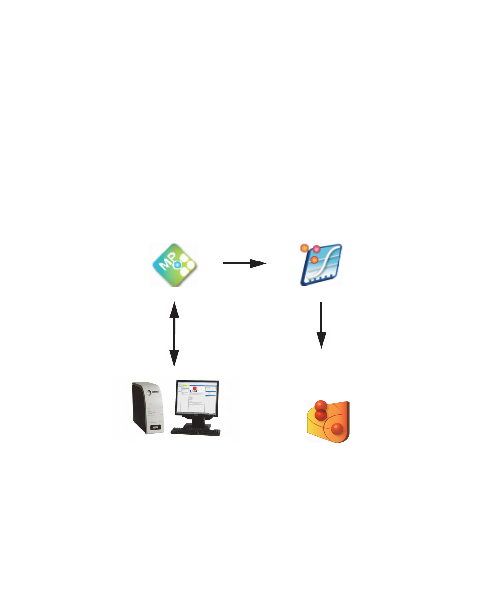
Bio-Plex Manager™ MP is an application that allows you to run and maintain your
MAGPIX instrument. MAGPIX monitors the state of your instrument and
recommends routines to keep the instrument in good working order, and it also
recommends maintenance routines to resolve problems. With
Bio-Plex Manager MP, you do not have to keep track of when to calibrate your
instrument or verify the calibration settings. Its easy-to-use interface facilitates
creating and running your protocols. Bio-Plex Manager MP works with any MAGPIX
instrument purchased from any vendor.
You will use two software applications, Bio-Plex Manager MP 1.0 and
Bio-Plex Manager 6.x to run your experiments and analyze your results. Both
software applications are required and are shipped along with the MAGPIX
instrument.
Use Bio-Plex Manager MP to do the following:
Operate the MAGPIX instrument
Maintain the instrument
Define protocol parameters and initiate plate readings
Use Bio-Plex Manager 6.x to do the following:
Review and optimize results
Export results to Microsoft Excel or other third-party analysis software
Export results to Bio-Plex Data Pro™ for analysis of your experiment
(grouping biological replicates and identifying statistically significant
changes)
User Guide | 7
Page 10
1 | Introduction
Bio-Plex Data Pro is an optional software application that allows you to do further
analysis of your results:
Identify and group biological replicates
Determine statistically significant changes
Generate and export charts, heat maps, and tables
Bio-Plex Data Pro (catalog #171-001513 and #171-001523) is a separate product
that can be purchased from Bio-Rad.
MAGPIX Operation
Bio-Plex Manager MP
MAGPIX
Data Review
and Optimization
Bio-Plex Manager 6.x
Experimental Analysis
and Interpretation
Bio-Plex Data Pro
8 | Bio-Plex Manager MP Software
Page 11

2 Creating Protocols
About Protocols
A protocol contains the parameters of a Bio-Plex Manager™ MP software run. It
includes information about the analytes included in the run, the plate wells to be
read, the concentrations of standards, and instrument settings. These parameters
are saved in the result along with the data from the reading.
You can save a protocol and reuse it or modify it for another reading. Each time you
run the protocol, a new result is created and stored in the database.
You set up your protocol from the protocol dialog box. There are three phases to
setting up your protocol that correspond to the three panes in the protocol dialog
box:
Select Analytes – select an assay panel and the analytes for your
experiment.
Format Plate – specify which wells are to be read and the sample type of
each well.
Standards Info – specify the concentrations of your standards.
User Guide | 9
Page 12
2 | Creating Protocols
Navigating to the Protocol Dialog Box
Protocols are created from the protocol dialog box. There are a number of ways you
can get to the protocol dialog box.
To navigate to the protocol dialog box
1. Click Create/Run Protocols in the navigation bar.
2. Do one of the following:
Click New.
Click New From and select a protocol from the Select Protocol dialog box.
With an open protocol in the Create/Run Protocols view, click Edit.
10 | Bio-Plex Manager MP Software
Page 13

Creating a Protocol
The following are the steps to create a new protocol.
To create a new protocol
1. Click Create/Run Protocols in the navigation bar.
2. Click New to open the New Protocol dialog box.
3. Click the Assay Panel dropdown list and select an assay panel.
4. Select the analytes for your experiment.
5. Click Format Plate.
6. Format the wells to use in the experiment. For more information on formatting
wells, see
7. Click Standards Info.
8. From the Standard Lot dropdown list, select the standard lot you want to use
with this protocol.
Note: If no standard lots appear in the list, you must first create a standard
lot for your assay panel. For more information, see
Lots on page 50.
Formatting Plates on page 14.
Creating a Protocol
Creating New Standard
9. Select the dilution factor from the Dilution Factor dropdown list. For more
information, see
10. Click OK.
11. (Optional) Click Save As to save the protocol.
Note: Save the protocol if you want to run it again at a later time or if you
want to use it as a template for another protocol. For more information on
using the protocol as a template, see
12. (Optional) In the Save Protocol dialog box, enter the protocol name and click
OK.
Note: Protocols created on one computer cannot be exported and used on
another computer running Bio-Plex
Selecting a Standard Lot on page 21.
Reusing a Protocol on page 23.
Manager MP.
User Guide | 1 1
Page 14

2 | Creating Protocols
About Analytes
Bio-Plex Manager MP software groups analytes by panels. Preconfigured panels of
analytes that correspond to off-the-shelf Bio-Plex® assays can be selected. These
assays include human, mouse, and rat cytokines and phosphoproteins, as well as
the newer human angiogenesis, diabetes, isotyping, and acute phase assays. The
following assays are currently not available for the MAGPIX instrument: nonhuman
primate diabetes, canine kidney tox, rat and human kidney tox, angiogenesis, and
acute phase. You can add other panels to this list or create custom panels that
include only the analytes you use in your experiments.
Note: After you select the assay panel, you select which analytes you want to
appear in your reports. During a reading, the array reader detects all the
analytes in the sample, including any analytes you excluded from selection.
However, only the selected analytes are included in the final reports and tables.
After the run is completed, you can always edit the protocol, select any
analytes that were previously omitted, and the data for those analytes will
appear in the tables.
Each analyte is listed by name and region. The region number refers to the area of a
fluorescent color map that identifies the analyte’s bead region. Each bead region is
embedded with specific quantities of two fluorescent dyes. The array reader detects
the combination of these fluorochromes and associates the bead region with a
unique region on the color map. Therefore, the location on the map identifies the
bead region and its associated analyte.
Each analyte on a Bio-Rad preconfigured panel is identified by a unique region.
However, analytes on different panels may occupy the same region. If you pick
analytes from more than one panel, only one analyte for a particular region can be
selected. Bio-Plex
12 | Bio-Plex Manager MP Software
Manager MP warns you if there is a conflict.
Page 15
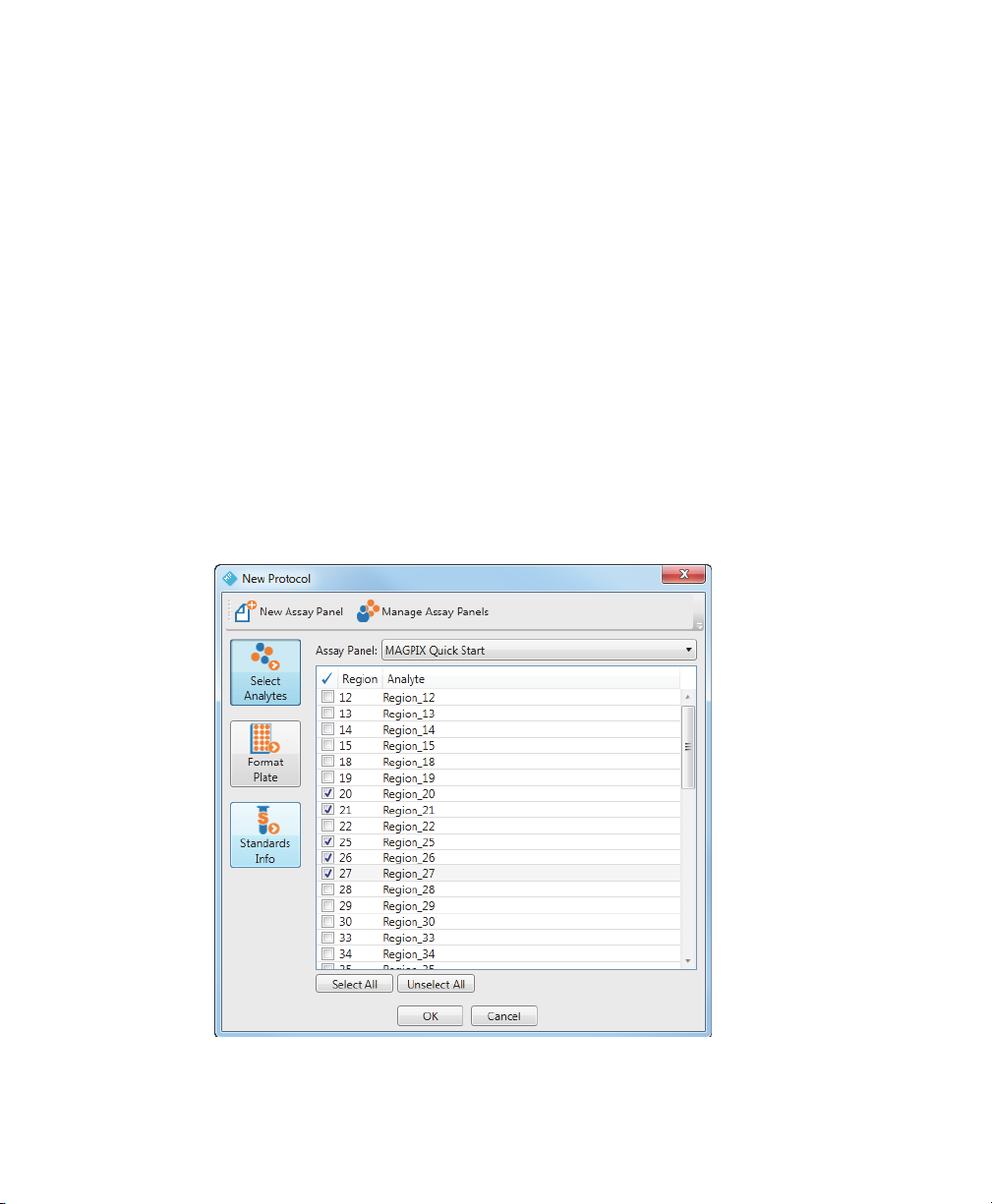
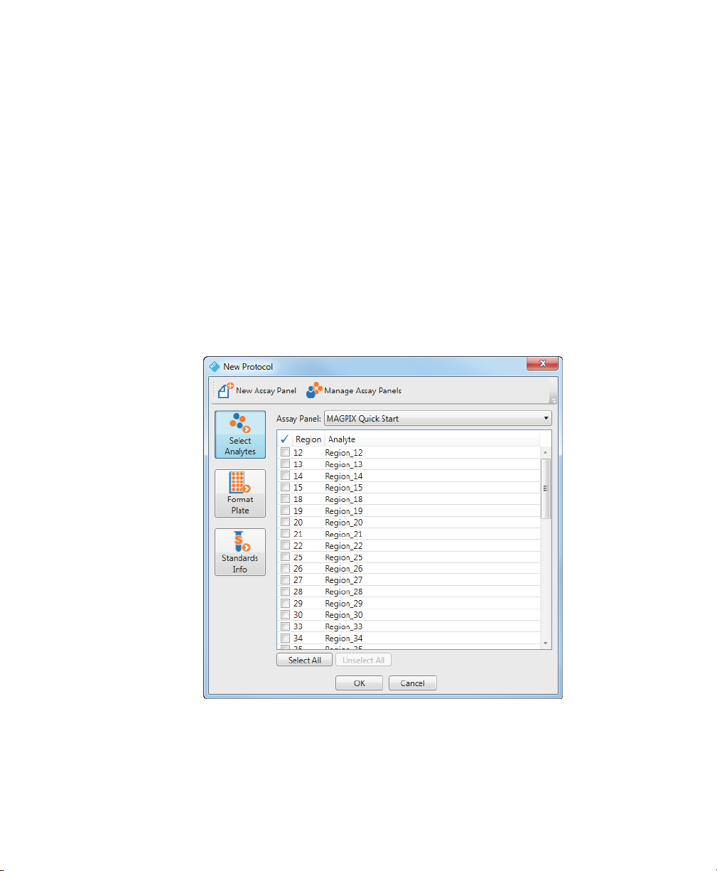
Selecting Analytes
After you select the assay panel you want to use in your experiment, you select the
analytes you are interested in.
To select an analyte
1. From the protocol dialog box, click Select Analytes.
2. From the Assay Panel dropdown list, select an assay panel.
3. Click the checkboxes to select the analytes to include in your protocol or click
Select All to select all analytes.
4. Click OK.
The following figure shows the MAGPIX Quick Start assay panel with analytes in
r
egions 20, 21, and 25 through 27 selected.
Selecting Analytes
User Guide | 1 3
Page 16
2 | Creating Protocols
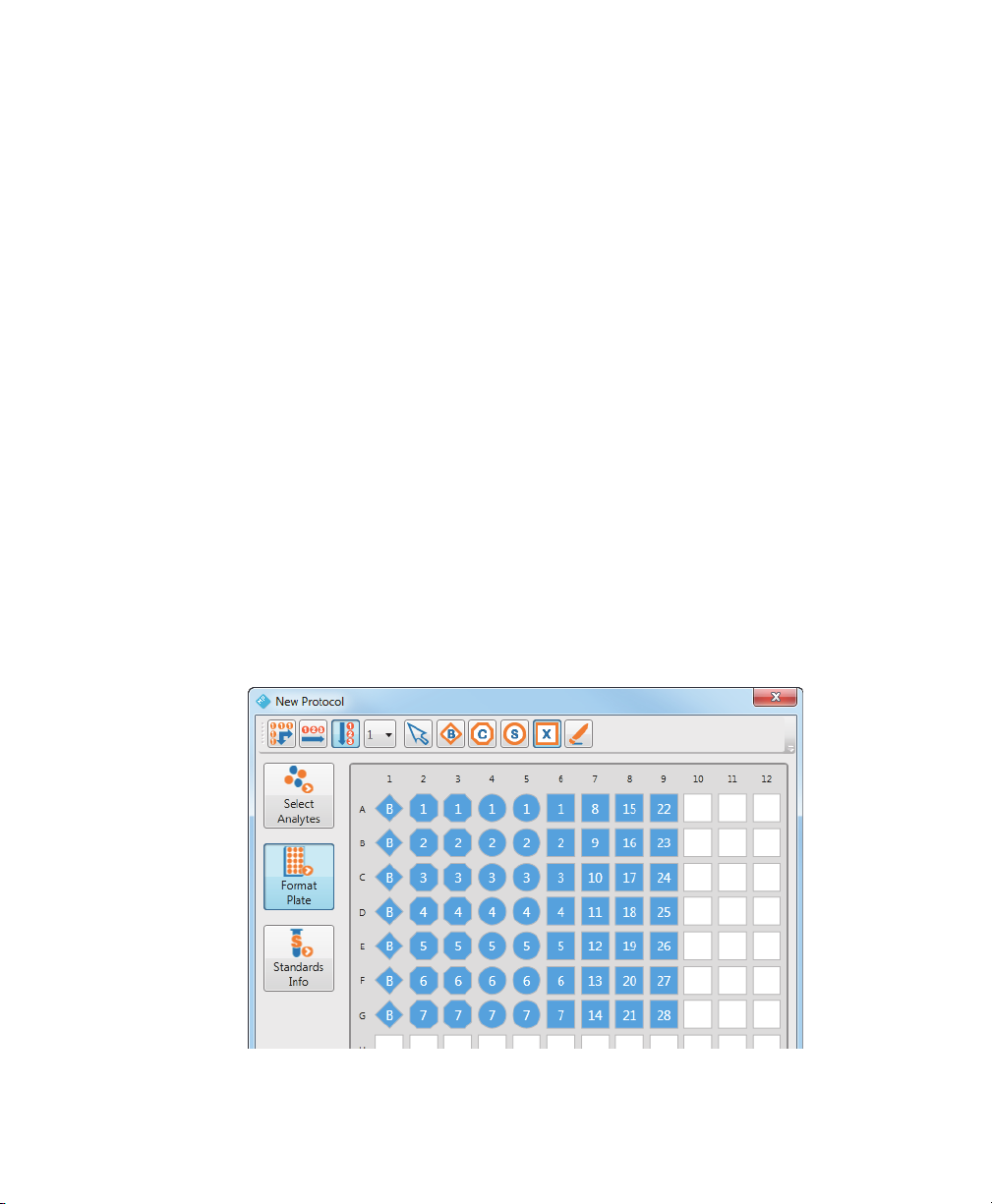
Formatting Plates
The array reader uses the plate formatting to identify which wells are to be read and
Bio-Plex Manager MP uses it to determine how to analyze the different samples in
each well.
Note: Only formatted wells are read by the array reader. Undefined wells are
not r
ead.
To format a plate
1. Navigate to the protocol dialog box.
2. Click Format Plate.
3. Click the button in the toolbar for the type of well you want to format.
4. Click the wells in the template that you want defined with this well type.
Formatted wells are colored blue with a specific shape to identify the well type.
Contr
ol, Standard, and Unknown wells are numbered. Blank wells are specified
with the letter B. For more information on the well types, see Well Types on
page 16.
14 | Bio-Plex Manager MP Software
Page 17
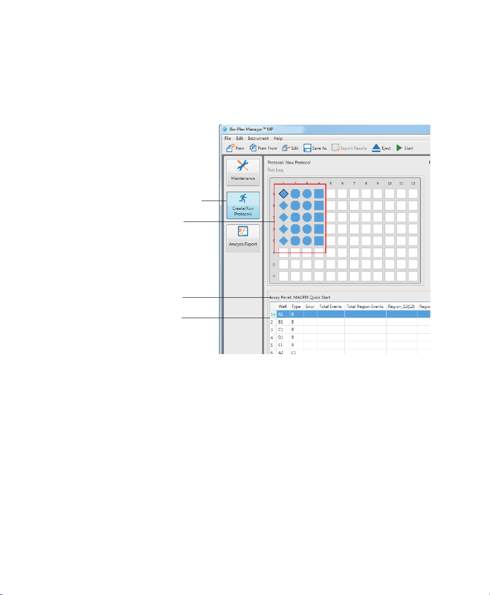
Formatting Plates
The template diagram in the Create/Run Protocols view displays the formatted wells
in your protocol and the raw data table is populated with the well location and
sample type.
Create/Run Protocols view
Formatted wells
Name of assay panel
Raw data table
User Guide | 1 5
Page 18

2 | Creating Protocols
Well Types
The following are different well types that you can specify on the plate:
Blank Standard Undefined
Control Unknown
Blank Wells
In certain types of assays, such as the Bio-Plex phosphoprotein assay, it might
be useful to subtract the assay backgr
ound from the readings of standards,
controls, and unknown samples. Prepare blank wells that contain all of the
assay components excluding the sample. Blank wells are read along with the
rest of the assay. Bio-Plex Manager 6.x then subtracts the mean background
r
eading of these wells from the fluorescence intensity values of the wells
containing standards, controls, and unknowns.
Control Wells
Control wells contain samples of known concentration. The observed
concentration of the contr
ol wells is compared to the expected concentration
and calculated at the end of the reading.
Standard Wells
Standard wells contain analytes of known concentration. A series of known
concentrations of an analyte is used to generate a standar
fluorescence intensity compared to analyte concentration. The regression
equation for the curve is used to calculate the concentration of analytes in the
unknown samples and controls.
16 | Bio-Plex Manager MP Software
d curve of
Page 19

Formatting Plates
Unknown Wells
The unknown wells contain samples of unknown concentration. These samples
are taken from the subjects of your experiments.
Undefined Wells
Use the Undefined wells button to remove the definition of a well. Undefined
wells are not read by the array reader.
Autofilling Well Numbers
Use the Autofill feature to quickly define a well type for multiple wells.
Autofill Across numbers the wells sequentially from left to right, then top to
bottom
Autofill Down numbers the wells sequentially from top to bottom, then left
to right
To use Autofill to format the plate
1. In the New Protocol window, click Format Plate.
2. Click Autofill Across or Autofill Down.
3. Click the well type.
4. Click and drag your cursor in the plate over the wells you want to format.
User Guide | 1 7
Page 20
2 | Creating Protocols
In the following example, Autofill Down was used to create 20 Unknown wells.
Note, the numbering of the wells is top to bottom, then left to right. The arrow
shows the path of the cursor as it is dragged across the plate template.
Defining a Replicate Group
You can quickly format a replicate group.
To define a replicate group
1. Click Turn Autofill Off.
2. Click and drag your cursor over the wells that contain the same sample.
The wells are labeled with the same number.
Autofilling Replicate Groups
You can quickly format multiple replicate groups at one time.
To format a replicate group
1. Click Autofill Across or Autofill Down.
18 | Bio-Plex Manager MP Software
Page 21
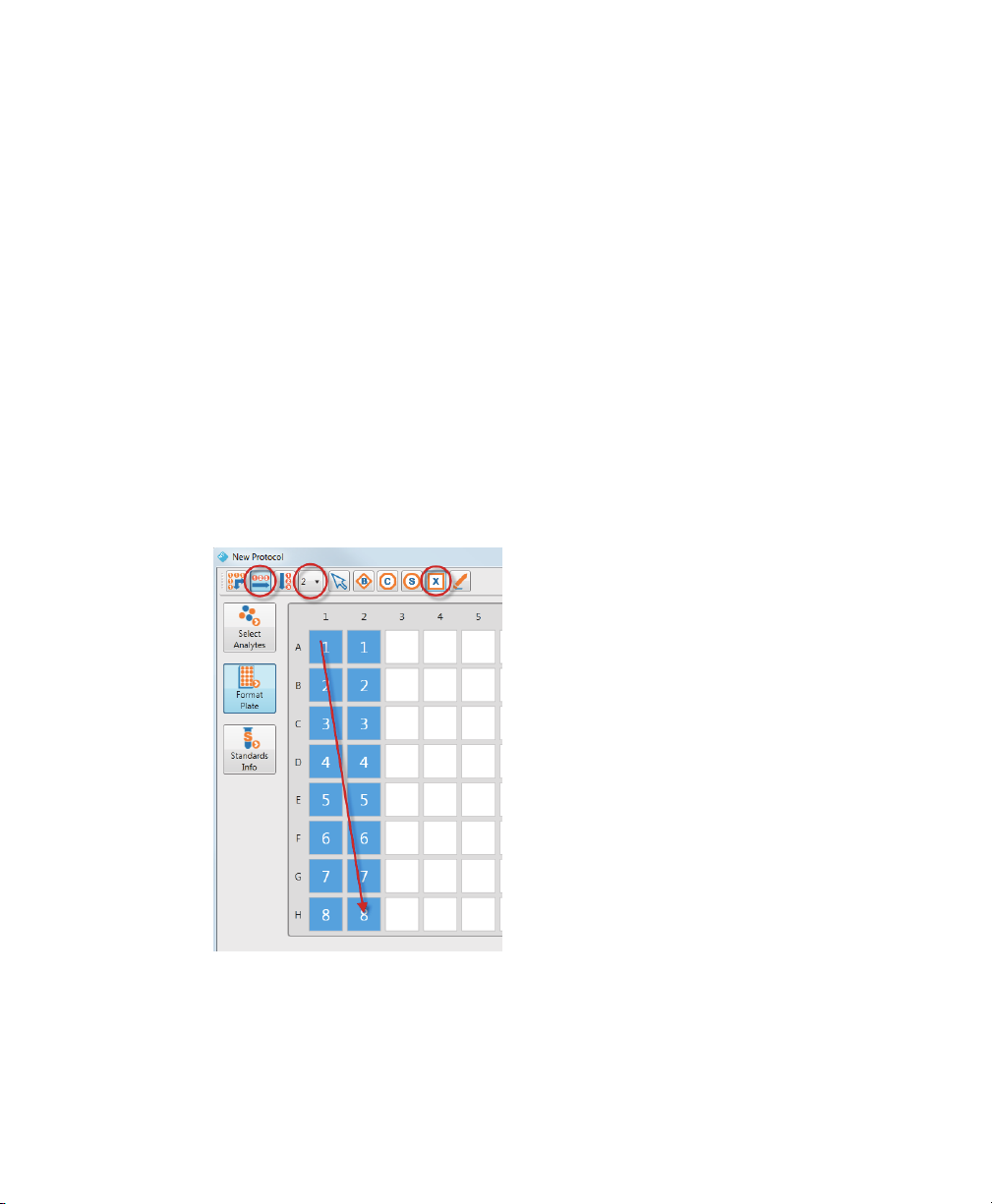
Formatting Plates
2. Click the Set Replicate Size dropdown list and pick the number of replicates in
the group.
Note: The maximum size you can specify with the Set Replicate Size
dr
opdown list is eight.
Tip: You can create replicate groups that are larger than eight by clicking
T
urn Autofill Off, setting the replicate size to 1, and selecting the number of
wells you want in your replicate group.
3. Click the well type.
4. Click and drag your cursor over the wells on your plate.
In the following example, Autofill Across is selected and the replicate size is set to 2.
Eight gr
oups of replicates of Unknown well type were created. Each row represents
a replicate group. The arrow shows the path of the cursor as it is dragged across the
plate template.
User Guide | 1 9
Page 22

2 | Creating Protocols
Removing the Well Formatting
Removing the formatting of a well returns it to its unformatted state. Unformatted
wells are not read by the array reader.
To remove the formatting of a well
1. Click Undefined.
2. Click and drag your cursor over the wells you want to clear.
The formatting is removed and the wells return to their unformatted state.
Changing the Well Formatting
You can overwrite the formatting of a well by simply applying another sample type
over the wells.
To change the formatting of a well
1. Click the button for the sample type you want to use.
2. Click and drag your cursor over the wells whose format you want to change.
The wells are now formatted with the new well type.
About Standards
Standards are analytes of known concentration. Standards are used to generate a
standard curve of values using one of the several regression methods included in
Bio-Plex
Manager 6.x. This curve is used to calculate concentrations of your
unknowns.
In Bio-Plex Manager MP, you define your standard lot, including the starting
concentration for each of the analytes. This definition is stored and it can be reused
each time you run a plate with those analytes.
20 | Bio-Plex Manager MP Software
Page 23
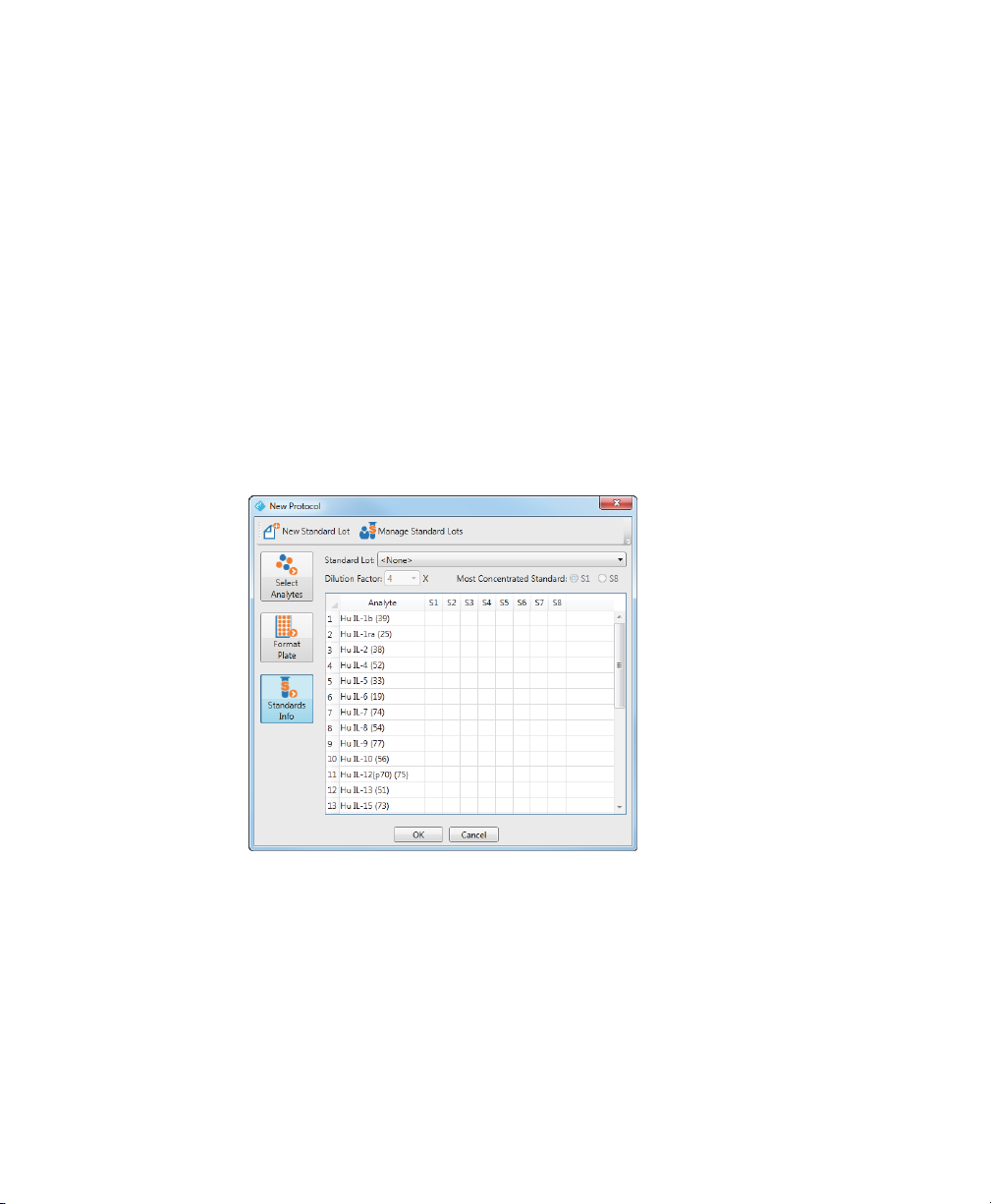
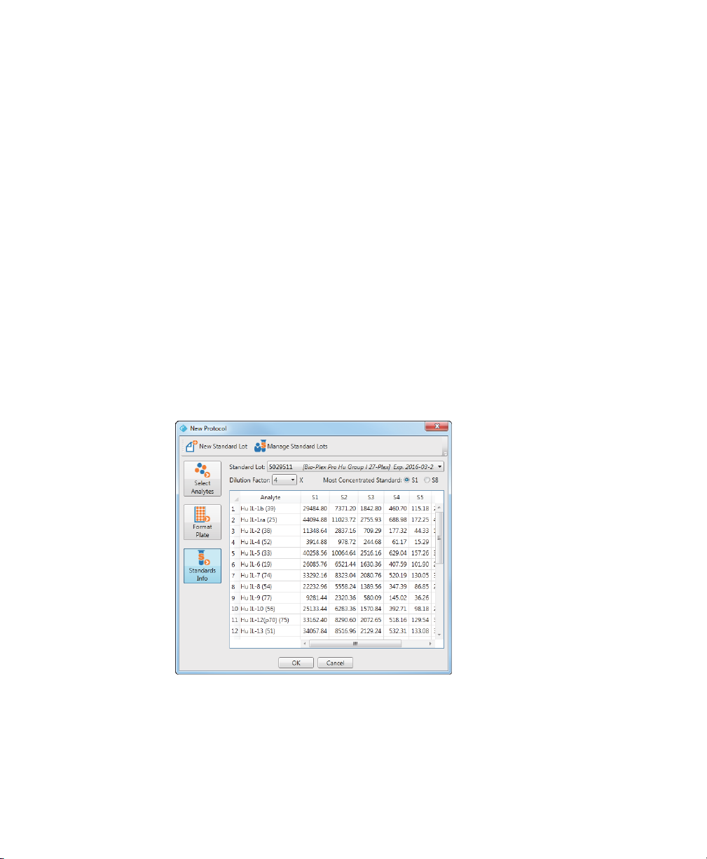
Selecting a Standard Lot
Before you can select the standard lot to use with your protocol, you must first
select your analytes, format the standard wells, and create a standard lot for the
assay panel you are using if one has not already been defined for your analytes.
To select a standard lot for your protocol run
1. From the protocol dialog box, click Standards Info.
The table displays the analytes you selected on the Select Analytes pane. Each
analyte appears as a r
you defined on the Format Plate pane. In this example, eight standard wells
were selected on the Format Plate pane, and therefore, there are eight
columns: S1, S2, and so on.
ow in the table. There is a column for each standard well
Selecting a Standard Lot
Note: The Standards Info pane is disabled until you select your analytes
and format your standard wells.
2. From the Standard Lot dropdown list, select the standard lot you want to use
with this pr
otocol.
User Guide | 2 1
Page 24
2 | Creating Protocols
Only the standard lots that contain the selected analytes appear in the list. If the
list is empty, then there are no defined standard lots that include the analytes
you selected and you must create a standard lot. Or if the list does not include
the standard lot you are using, then you must create a standard lot definition.
For more information on creating standard lots, see Creating New Standard
Lots on page 50.
Note: The predefined standard lots are identified by their lot numbers.
Included in par
date. In the example, 5029511 [Bio-Rad Pro Hu Group 27-Plex] Exp
2016-03-30, 5029511 is both the name of the standard lot and its lot
number.
3. Select the dilution factor from the Dilution Factor dropdown list.
The table autopopulates with the concentrations using the starting
concentration specified for that standar
entheses is the name of the assay panel and the expiration
d lot and the dilution factor.
Note: Use Most Concentrated Standard to specify whether the first well or
the last well contains the highest concentration of the analyte.
22 | Bio-Plex Manager MP Software
Page 25

Reusing a Protocol
You can use a saved protocol as a template for your experiment. You can make
changes to a copy of the saved protocol — for example, you might change the
number of unknown samples.
To reuse a saved protocol
1. Click New From on the toolbar to open the Select Protocol dialog box.
2. Select the protocol you want to use and click OK.
3. In the protocol dialog box, make any changes to the selected analytes, the
plate formatting, and the standards information.
4. When you are done making changes, click OK.
Editing a Protocol
The Edit command opens the protocol dialog box for the protocol currently
displayed in the Create/Run Protocols view. You might want to edit a protocol in the
following situations:
Reusing a Protocol
You make changes to a saved protocol to match the changes in your
experiment. The most common change is to the number of unknown
samples in the experiment.
You run a protocol and discover that there is a low bead count, indicating
that the wrong analytes might have been selected. You can change the
selection of analytes in the protocol dialog box.
User Guide | 2 3
Page 26

2 | Creating Protocols
24 | Bio-Plex Manager MP Software
Page 27

3 Running Protocols
Once your protocol is created, you are ready to run the protocol. The result is
displayed in the raw data table and bead map and it can be exported to
Bio-Plex
Manager™ 6.x software for analysis. You can interrupt a run at any time,
make any necessary changes to the protocol, and resume the run with no loss of
data. Bio-Plex
informing you when it detects problems with your run.
Running the Recommended Routine
Run the routine in the Recommended Routine section of the Maintenance view each
day you use the MAGPIX instrument. This keeps the instrument free of bubbles and
ensures that it is operating according to specifications.
To run the recommended routine
1. Navigate to the Maintenance view.
2. In the Recommended Routine section, click Select to select the routine.
3. Fill the reservoirs and the well strip with the solutions indicated in the Reagent
Manager™ MP software provides graphical clues and alerts
Block.
4. Click Start.
5. When the routine is completed, a dialog box displays indicating that the routine
is successfully completed.
You can monitor the progress of the routine; for more information, see Monitoring
the Routine on page 62.
User Guide | 2 5
Page 28

3 | Running Protocols
Plate Handling Guidelines
Before starting the run, note the following plate handling guidelines and warnings:
Protect your assay microspheres from light. Once photobleached, the
beads are no longer usable. You must care for the microspheres properly
to maintain your product warranty.
When using a filter plate and wrapping the plate, avoid touching the
bottom of the wells. The sample may wick or leak from the well bottom.
Should this occur, it can cause problems when reading the plate.
Make sure you have added at least 125 µl of sample to all the wells
specified in your plate template before starting a protocol run. If the array
reader attempts to draw sample from an empty well, air is sucked into the
sample loop and injected into the flow chamber. When this happens,
bubbles form in the cuvette and interfere with the analysis. Should this
occur, perform a Clear Bubbles procedure (see
page 77), then rerun the protocol.
Shake the microplate on a plate shaker for 30 seconds prior to performing
a reading.
Clear Bubbles Routine on
For some experiments the temperature of the plate must be maintained at a
particular temperature. See
26 | Bio-Plex Manager MP Software
Using the Plate Heater on page 28 for more information.
Page 29

Plate Types
The plate height adjustment procedure adjusts the probe setting for four
consumables, the well strip, and the reservoirs in the reagent block. When you run
your protocol, you must specify one of the following plate types.
Plate Types
Plate Type Compatible Consumable Distance
from Platform
(mm) *
Flat bottom
plate
Filter plate Millipore multiscreen plate (for example,
PCR plate Bio-Rad low-profile unskirted PCR plate
Auxiliary plate Nunc PolySorp (for example, 475094),
* This is the distance between the platform and the inside bottom of the plate well.
Bio-Plex Pro™ flat bottom plate (black
plate comes with Bio-Plex Pro assays,
catalog #171-025001)
MSBVN1210)
(for example, MLL-9601)
Nunc MaxiSorp (for example, 445105)
3.94
3.05
2.79
3.30
For other plate types, check the manufacturer’s specifications to determine the
distance from the surface of the MAGPIX platform to the bottom of the well.
The probe backs off 1 mm after it makes contact with the probe height adjustment
plate. Ther
efore, you need to add 1 mm to the distance in the table to get the
correct probe height.
For example, if the specification for your plate type is 3.4 mm, you can use the
auxiliary plate (3.3 mm) because the actual setting, after running the pr
obe height
adjustment, is 4.3 mm. This gives an allowance of 0.9 mm above the plate’s well
bottom for sample aspiration.
User Guide | 2 7
Page 30

3 | Running Protocols
Using the Plate Heater
For some experiments, for example nucleic acid testing, you may need to heat and
maintain the temperature of the plate with the MAGPIX plate heater. You can turn
the heater on from any view in Bio-Plex Manager MP and set the temperature of the
plate from 35–60ºC in 0.5º increments.
Note: While the plate temperature is being set, you cannot run your protocol.
To use the plate heater
1. In the dashboard, select the “Plate heater off” checkbox to turn the heater on.
The “Turning on” message appears. When the heater is turned on, Set Temp is
displayed.
2. Use the left- and right-pointing triangles to set the plate temperature.
The temperature can be set from 35–60ºC in 0.5º increments.
When the temperature of the plate falls within range of the set temperature, the
thermometer turns green.
3. When you are done, select Set Temp to turn the heater off.
Running the Protocol
After you create your protocol, you are ready to run it. Refer to Chapter 2, Creating
Protocols for more information on creating protocols.
Note: You can run only protocols created in Bio-Plex Manager MP. You cannot
run protocols created in other versions of Bio-Plex
Bio-Plex
Manager 6.1.
The data from each run are stored as a result in the Bio-Plex Manager MP database.
Result names must be unique. You can retrieve the data by exporting the result to
Bio-Plex
Manager 6.x.
28 | Bio-Plex Manager MP Software
Manager such as
Page 31

Running the Protocol
To run your protocol
1. In the Create/Run Protocols view, click Start.
The microplate platform automatically ejects.
2. In the Run Settings dialog box, enter the name of the result in the Result Name
box.
The result name is the name that the data are stored under in the database.
This name is case-sensitive and must be unique. Ther
efore, RESULT 1 is not
the same as result 1.
3. (Optional) Enter the Plate ID.
You can specify anything here that will help you distinguish your experiments
and r
esults.
4. Specify the type of plate in the Plate Type List.
If you do not see your plate listed here, see Using the Plate Heater on page 28
to determine the equivalent match for your plate type.
5. (Optional) In the Pre-Run Routine list, select any routines you want executed
befor
e the protocol run.
Note: A Rinse routine is always run before a plate is read. This routine is
run in addition to any pr
e-run routine specified here.
User Guide | 2 9
Page 32

3 | Running Protocols
If you select a pre-run routine, refer to the Reagent Block diagram and fill the
appropriate reservoirs with the specified fluids.
6. (Optional) In the Post-Run Routine list, select any routines you want executed
after the protocol run.
Note: Bio-Rad recommends you run the Wash Between Plates routine
after each protocol run to prevent traces of sample or other debris from
collecting inside the Bio-Plex® suspension array system.
If you select a post-run routine, refer to the Reagent Block diagram and fill the
appropriate reservoirs with the specified fluids.
7. Accept the default for “Stop runs with low bead count” or clear the checkbox if
you do not want the run interrupted.
By default, the run is interrupted if three consecutive wells have a bead count of
less than 20.
8. Click Create/Run Protocols.
The plate retracts and Bio-Plex Manager MP starts the run.
30 | Bio-Plex Manager MP Software
Page 33

Running the Protocol
Reading the Plate
In the template diagram in the Create/Run Protocols view, the blue wells indicate
which wells have been formatted. Only formatted wells are read. Each well is read in
turn, from top to bottom, then from left to right. A pulsing triangle shows you which
well is currently being read.
Protocol name
Template diagram
Well E2
Run commands status
The Run Commands status displays information about the well that is currently
being read. In the preceding example, Well E2 is being read. The Run Commands
status indicates when the r
eading begins and ends for the current well.
User Guide | 3 1
Page 34

3 | Running Protocols
Once the reading for a well is complete, the pulsing triangle resolves into one of the
following symbols indicating the result of the reading.
Symbol Description
The results are displayed in the Raw Data table and the Bead Map.
Raw Data Table
As the wells are read, the Raw Data table is populated with the results. The table
displays the well location and the well type for all formatted wells. As
Bio-Plex Manager MP completes reading each well, the Raw Data table is
populated with the r
you selected are displayed for each well.
The bead count for all analytes is
20 or higher.
The bead count for one or more
analytes is below 20 bead
events.
No data were found or an error
occurred while reading the well.
esults for that well. The fluorescence intensities of the analytes
Note: During a reading, the array reader detects all of the analytes in the
sample, including any that you have not selected. However
are not selected in the protocol are not included in the table, even if they are
detected. After a reading you can edit the protocol and change the selection of
32 | Bio-Plex Manager MP Software
, any analytes that
Page 35

Bead Map
your analytes. The new analytes, if detected during the run, will then appear in
the table.
Column Heading Description
Well Location of the well on the plate template.
Type Identifies the type of well, Blank, Control, Standard,
Unknown, and the sample. For example, C1 is the first
contr
ol sample and S4 is the fourth standard sample.
Total Events Total bead events recorded for that well, including
unclassified events (events that fall outside the 50
r
egions). This column can be displayed or hidden
using a toggle command.
Total Region
Events
Region_##(##) When bead region counts are displayed, there are two
Total bead events recorded within the 50 defined
r
egions. This column can be displayed or hidden
using a toggle command.
numbers. The first number is the fluor
intensity for that analyte. The second number, in
parentheses, is the number of bead events for that
region.
If there are low bead counts for any of the selected
analytes, the following symbols appear:
There are fewer than the recommended
*
50 beads for one or more analytes.
escence
Bead Map
The bead color map is a density dot plot of the events in a reading for a selected
well. Different colored dots in the map represent different numbers of events at
those data points. There are 50 available regions in the bead map.
There are fewer than 20 beads for one or
mor
e analytes.
User Guide | 3 3
Page 36

3 | Running Protocols
The x-axis is the Classification 1 channel and the y-axis is the Classification 2
channel. These channels measure the embedded fluorochromes in each bead,
which are used to identify the bead set and corresponding analyte. The resulting
data point clusters in the map represent the different bead sets in the assay and
their associated analytes.
Tip: Use Maximize View to expand the bead map to fill the entire window.
Once maximized, you can use the Zoom tool to focus further on a particular
area in the bead map.
Note: Each bead set generates a cluster of data points, rather than a single
point, because of minute variations in fluorochrome levels and intensity among
the beads in the set.
The white areas on the map indicate the expected regions of the selected analytes.
When you move your cursor over these areas, the name of the analyte appears in a
tool tip. The data point clusters should fall within these regions. If one or more
clusters do not fall within the white areas, there may be a problem with the beads
such as photobleaching. Or the analyte selections in the protocol may be incorrect.
If all the data clusters have shifted out of the white regions, there may be
microbubbles in the cuvette. The bead map can be used to confirm that the bead
sets are correctly selected, measured, and identified.
Interrupting a Run
The results for each run, whether the run is completed or interrupted, are saved to a
unique result which can later be retrieved and viewed. Any data that were read up to
the point the run is interrupted are saved to the result name you specify in the Run
Settings dialog box. When you are ready to run the protocol again, return to the Run
Settings dialog box.
To interrupt a run
Click Stop to interrupt a run.
34 | Bio-Plex Manager MP Software
Page 37

When a sample is being read, the Start button changes to a Stop button.
Note: When you click Stop, Bio-Plex Manager MP finishes reading the current
well before it stops the run. Therefore, you may have to wait up to a minute
before Bio-Plex
Manager MP responds to another command.
Resuming a Run
You can interrupt a run and make changes to your protocol, including changing the
analytes you are interested in or correcting the format of your plate. You can run the
protocol again and start where you left off or start from the beginning and read the
entire plate.
To resume a run
1. From the Create/Run Protocols view, click Start.
2. In the Run Settings dialog box, either accept the default or enter a different
name in the Result Name field.
By default, the Result Name you entered for the first run is appended with a
number surrounded by square brackets. For example, if the result name you
entered is Test, when you return to the Run Settings dialog box to run the
protocol again, the result name is Test [1]. With each subsequent run, the
number is incremented.
Resuming a Run
3. In the Well Selection diagram, specify the wells you want read.
Bio-Plex Manager MP reads only selected formatted wells. A black border
indicates the selected wells. You can:
Read only the wells that were not read on the last run. This is the default,
as shown in the figure that follows. In this example, when the run resumes,
it will start with well A2.
Click Select All to read all the wells.
Click on a subset of the formatted wells to read only those wells.
Tip: Use Shift + Click to select more than one well.
User Guide | 3 5
Page 38

3 | Running Protocols
Encountering and Resolving Low Bead Counts
Bio-Plex Manager MP notifies you when a low bead count is detected:
The well with the low bead count displays a warning symbol.
A warning symbol is displayed for the region in the Raw Data table if a low
bead count occurred for that particular analyte.
You can specify that Bio-Plex Manager MP stop the run if it encounters three or
mor
e consecutive wells with low bead count of less than 20. In the Run Settings
dialog box, select “Stop runs with low bead count.” If a low bead count is
encountered, the run is stopped and a dialog box appears with a suggested
solution.
In addition, a warning symbol is displayed in the affected wells in the plate template
and for the applicable analytes in the raw data table.
36 | Bio-Plex Manager MP Software
Page 39

Encountering and Resolving Low Bead Counts
1
2
3
LEGEND
1 Warning symbol indicating wells with a low bead count
2 Warning symbol indicating region in which there is a bead count of fewer
than 20 beads
3 Asterisk (*) indicating region in which the bead count is lower than the
r
ecommended 50 beads
Important: Bio-Plex Manager MP will provide warning messages when a low
bead count occurs with recommended steps to resolve the problem. These
include reviewing your protocol, performing maintenance on the instrument,
and running maintenance routines. It is important that you perform the steps in
the recommended order because this increases the likelihood that the problem
will be resolved.
User Guide | 3 7
Page 40

3 | Running Protocols
Run Results Table
The data from each run are saved as a result in the MAGPIX database. Each result is
a row in the run results table.
The following table describes the information in the run results table.
Column Name Description
Name Name of the result set
Acquisition Time Time stamp of when the protocol was run
Assay Panel Assay panel used in the run
# Analytes Number of analytes selected in the protocol
Description User-defined description
Tip: Click the column header of any column to sort the table by that column.
38 | Bio-Plex Manager MP Software
definition
Page 41

Exporting Data to Bio-Plex Manager 6.x
Exporting Data to Bio-Plex Manager 6.x
Before data can be analyzed in Bio-Plex Manager 6.x, the Bio-Plex Manager MP
run result must first be saved to a file. This file can then be exported to
Bio-Plex
Manager 6.x.
You can export your results in either of the following ways:
Export your results immediately following a protocol run from the Create/
Run Protocols view. For more information, see
Create/Run Protocols View on page 40.
Export your results at a later time from the Analyze/Export view. For more
information, see
Exporting Data from the Analyze/Export View on page 41.
Note: You can export your data once the plate reading is completed. If you
select a post-run routine to be run once the run is completed, you do not have
to wait for the routine to complete before exporting your data.
Once the file is saved, it can be viewed in Bio-Plex Manager 6.x in one of the
following ways:
Exporting Data from the
If Bio-Plex Manager 6.x is installed on the same computer where you are
running Bio-Plex
Bio-Plex
Manager 6.x after the file is saved. If you respond Yes, the result
file is opened in Bio-Plex
If Bio-Plex Manager 6.x is not installed on your computer, then you must
copy the saved file to a computer where Bio-Plex
Manager MP, then you are prompted to view the result in
Manager 6.x.
Manager 6.x is installed
and import it into the software.
User Guide | 3 9
Page 42

3 | Running Protocols
Exporting Data from the Create/Run Protocols View
You must first export the result to a file before you can analyze the data.
To export data from the Create/Run Protocols view
1. From the Create/Run Protocols view, click Export Results.
2. In the Export Results dialog box, navigate to where you want the run result to
be saved.
3. Enter the name of the file.
The default file name is the Result Name assigned in the Run Settings dialog
box, followed by a time stamp of the time of the export. For example,
Experiment 2013-02-12 13.04.08. You can accept the default name or enter a
different name for the file.
4. Click Save.
A message appears informing you that the result file has been exported.
If Bio-Plex Manager 6.x is installed on the same computer where you are
running Bio-Plex
result in Bio-Plex
Manager MP, you are also asked if you want to open the
Manager 6.x
5. In the Export Results dialog box, click Yes.
Bio-Plex Manager 6.x is launched and the run result appears in the Raw Data
table.
Note: You are now in the Bio-Plex Manager 6.x application.
Bio-Plex
Manager MP continues to run and you can switch back and forth
between the two application windows.
40 | Bio-Plex Manager MP Software
Page 43

Exporting Data to Bio-Plex Manager 6.x
Exporting Data from the Analyze/Export View
The result from a protocol reading is stored in the run results table. (See Run Results
Table on page 38 for more information.) You can export your run result at a later time
from the Analyze/Export view.
To export data from the Analyze/Export view
1. Click Analyze/Export in the navigation bar.
2. Click the row of the run result you want to export.
3. Click Export Results.
4. Enter the name of the file.
The default file name is the run result name, followed by the time stamp of the
time of the export. For example, Experiment 2013-02-12 13.04.08. You can
accept the default name or enter a different name for the file.
5. Click Save.
A message appears informing you that the result file has been exported.
If Bio-Plex Manager 6.x is installed on the same computer where you are
running Bio-Plex
result in Bio-Plex
Manager MP, you are also asked if you want to open the
Manager 6.x
6. In the Export Results dialog box, click Yes.
Bio-Plex Manager 6.x is launched and the data result appears in the Raw Data
table.
Note: You are now in the Bio-Plex Manager 6.x application.
Bio-Plex
Manager MP continues to run and you can switch back and forth
between the two application windows.
User Guide | 4 1
Page 44

3 | Running Protocols
Exporting Data Results Multiple Times
As you analyze your data result in BPM 6.x, you may want to rerun the protocol
and generate a new result. As you switch between BPM MP and BPM 6.x, you
should be aware of how you name your result files. For example, assume you
save your result to a file called Exp. Region 21. After you examine the result in
BPM 6.x, you decide you want to make some changes to the protocol and run
it again. You return to BPM MP, edit the protocol, rerun the protocol, and export
the result a second time. When you are prompted to save the result, if you use
the same file name that you used for the first run (that is, Exp. Region 21) you
will overwrite the result file from the first run.
Note: Before you export your result from BPM MP to BPM 6.x, you must
close the Report Table view for Exp. Region 21 in BPM 6.x. If you do not
close the Report Table view for the first result file, BPM 6.x does not
recognize the new result file as an updated version of what is currently
displayed, and it does not load the new file. Therefore, you will continue to
see the old result.
Tip: Give your result files unique names to avoid running into this
problem. By default, a time stamp is appended to the end of the name of
the result file, making it unique.
42 | Bio-Plex Manager MP Software
Page 45

4 Managing Assay Panels
and Standard Lots
In Bio-Plex Manager™ MP software, you can select any of the Bio-Rad assay
panels for use in your experiments. These panels can be customized for your
experiments and reused or shared with colleagues who are using
Bio-Plex
Manager MP on other computers or in other locations.
Bio-Plex Manager MP makes it easy to manage your standards through predefined
standard lots. Standard lots are panels of assays with starting concentrations for
Bio-Rad kits. You can use the standard lot as provided or customize it to your
experiment. Standard lots can be shared with colleagues.
User Guide | 4 3
Page 46

4 | Managing Assay Panels and Standard Lots
Creating Assay Panels
You can create assay panels in the following ways from the Manage Assay Panels
dialog box:
Customize an existing assay panel (Edit button).
Create an assay panel by combining one or more existing panels (New
From button).
Enter your analytes into a new assay panel (New or New From buttons).
Import an assay panel (Import button).
44 | Bio-Plex Manager MP Software
Page 47

Creating Assay Panels
Customizing an Existing Assay Panel
Bio-Plex Manager MP provides a list of all the assay panels it manufactures along
with related analytes. In many instances you will take one of these panels and use it
as is. If your experiment uses only a subset of the analytes, Bio-Rad recommends
you edit the assay panel and delete any analytes you are not interested in and save
the panel with a new name. This customized panel makes it easier to run repeated
experiments using the same panel. For more information on editing an existing
assay panel, see
Editing an Assay Panel on page 47.
Creating an Assay Panel by Combining Existing Panels
You can create a new assay panel by combining existing panels. Once this panel is
created, you can cull the list and delete any analytes you are not interested in.
To create a new assay panel by combining existing panels
1. From the protocol dialog box, click Select Analytes.
2. Click Manage Assay Panels.
3. In the Manage Assay Panels dialog box, select the panels from the Assay Panel
list.
Note: You can select up to four assay panels.
4. Click New From.
5. In the New Assay Panel dialog box, enter a name for your assay panel.
6. Use the Add and Delete buttons to add or remove analytes from the list.
Tip: Click the number of the analyte to select the entire row.
7. Use the Up and Down buttons to reorder the analytes.
8. When you are done making changes to the panel, click OK.
In the Manage Assay Panels dialog box, the new panel appears at the top of
the list.
9. Click Close.
User Guide | 4 5
Page 48

4 | Managing Assay Panels and Standard Lots
From the protocol dialog box, you can now select this new assay panel from
the Assay Panel dropdown list.
Importing an Assay Panel
The Import feature can be used to share assay panels among users working on
different computers or to add new Bio-Rad assay panels. Once the panel is
imported, you can edit the panel or select it in your protocol.
You import an .xpnl file that contains one or more assay panels. If the imported
panel has the same name as an existing panel, Copy is appended to the name to
distinguish the imported assay panel from the existing one; for example, Assay
Panel - Copy.
To import an assay panel
1. From the protocol dialog box, click Select Analytes.
2. Click Manage Assay Panels.
3. From the Manage Assay Panels dialog box, click Import.
4. In the Import Assay Panels dialog box, navigate to the file you want to import.
5. Select the file and click Open.
A message informs you of the number of panels that were successfully
imported; for example, “Successfully imported 3 assay panels.” The imported
panels appear at the top of the Manage Assay Panels list.
6. Click Close.
From the protocol dialog box, you can now select any imported assay panels
from the Assay Panel dropdown list.
46 | Bio-Plex Manager MP Software
Page 49

Creating a New Assay Panel
You can create a new panel by starting with an empty assay panel and entering the
details for the assay.
To create a new assay panel
1. From the protocol dialog box, click Select Analytes.
2. Click New Assay Panel.
3. In the New Assay Panel dialog box, enter a name for the assay panel.
4. Enter the region and name of each analyte.
5. Click OK.
In the protocol dialog box, the new panel is added to the Assay Panel list.
Tip: You can also create a new assay panel from the Manage Assay Panels
dialog box.
Editing an Assay Panel
Editing an Assay Panel
You can make changes to an existing assay panel.
To edit an assay panel
1. From the protocol dialog box, click Select Analytes.
2. Click Manage Assay Panels.
3. Select the panel you want to edit and click Edit.
4. In the Edit Assay Panel dialog box, you can make the following changes:
Rename the assay panel.
Tip: Bio-Rad recommends you give the edited panel a new name.
This preserves the original Bio-Rad assay panel, and it eliminates
problems with overwriting your edited panels if you use the Restore
command or import updated panels from Bio-Rad.
User Guide | 4 7
Page 50

4 | Managing Assay Panels and Standard Lots
Use the Add and Delete buttons to add or remove analytes from the list.
Tip: Click the number of the analyte to select the entire row.
Use the Up and Down buttons to reorder the analytes.
5. When you are done making changes to the panel, click OK.
Customizing Your Assay Panel List
The Assay Panel list includes all the assay panels provided by Bio-Rad as well as
any panels you create. You may want to delete assay panels from the list because
you use only a subset of the published assays. If you delete a Bio-Rad assay panel,
you can always return it to the Assay Panel list using the Restore command. For
more information on restoring an assay panel, see
page 49.
To delete an assay panel
1. From the protocol dialog box, click Select Analytes.
2. Click Manage Assay Panels.
3. From the Manage Assay Panels dialog box, select one or more assay panels
and click Delete.
Restoring an Assay Panel on
Sharing Customized Assay Panels
If there are multiple users of Bio-Plex Manager MP in your environment, you can
customize an assay panel for your environment once and share it with other users.
Export the assay panel to a file and have your users import the panels into
Bio-Plex
Manager MP on their computers. You can also use the Export feature to
archive assay panels that you no longer need.
Note: You can export any number of assay panels at a time. All selected assay
panels are exported to a single file. When the file is imported, all panels are
imported. Users will not be able to selectively import panels from the file.
48 | Bio-Plex Manager MP Software
Page 51

To export an assay panel
1. From the protocol dialog box, click Select Analytes.
2. Click Manage Assay Panels.
3. Select the panel you want to export and click Export.
4. In the Export Assay Panels dialog box, enter the name of the file and click Save.
Restoring an Assay Panel
You may inadvertently delete an assay panel, or you may want to return to the
original version of a Bio-Rad panel that you modified. In these instances, you can
restore the assay panels that were originally distributed with the
Bio-Plex
Manager MP software using the Restore command. Any assay panels you
created are not affected.
WARNING! If any of the Bio-Plex Manager MP assay panels provided by
Bio-Rad have been modified, these will be overwritten with the Restore
command. If you want to save these edited panels, rename the panels first
before you use the Restore command.
Restoring an Assay Panel
To restore the Bio-Plex Manager MP assay panels
1. From the protocol dialog box, click Manage Assay Panels.
2. Click Restore.
About Standard Lots
Standard lots are definitions of analytes and their starting concentration for a
particular assay panel. When you create a protocol, you select one of the defined
standard lots. The standard lot definitions can be reused, thus eliminating the
tedious task of entering the standards each time you run an experiment.
Bio-Plex
Manager MP comes with a set of predefined standard lots.
User Guide | 4 9
Page 52

4 | Managing Assay Panels and Standard Lots
A list of the predefined standard lot definitions and any standard lots you create is
displayed in the Manage Standard Lots dialog box.
Creating Standard Lots
You can start with a blank standard lot and enter the required information for the
standard lot definition. However, you are more likely to take an existing standard lot
and modify it. You can share standard lot definitions using the export and import
features.
Creating New Standard Lots
To create a new standard lot
1. From the protocol dialog box, click Standards Info.
2. Click Manage Standard Lots.
3. In the Manage Standard Lots dialog box, click New.
4. In the New Standard Lot dialog box, enter a name for the standard lot.
50 | Bio-Plex Manager MP Software
Page 53

Creating Standard Lots
Tip: Bio-Rad recommends you include the lot number of the standards.
This will help you select the correct standard to use when running your
protocol.
5. In the Expiration Date field, enter the expiration date for this standard lot.
Tip: Click on the calendar and select a date.
6. From the Assay Panel dropdown list, select the assay panel you are using.
7. Select how the standard lot is defined by choosing one of the Define Standard
Lot By options.
In most instances, you will be using a serial dilution. For information on defining
custom concentrations, see Defining a Standard Lot with Custom
Concentrations on page 52.
8. Specify the starting concentration for the analytes.
User Guide | 5 1
Page 54

4 | Managing Assay Panels and Standard Lots
The starting concentrations are specified on a label or product insert in the
standard lot kit.
Tip: If the starting concentration for all of your analytes is identical, enter
the concentration for the first analyte. Select the entire row by clicking in
the first column in the table. Right click and select “Apply starting
concentration to all analytes” from the menu to populate the starting
concentration for all the analytes with the same number.
Defining a Standard Lot with Custom Concentrations
There may be times when you want to customize the dilutions of your standards.
For example, you might start with a dilution factor of 4 for the first three wells, then
dilute the standard in smaller increments for the next three wells.
To define custom concentrations for the analytes
1. In the New Standard Lot dialog box, select Custom for “Define Standard Lot
By.”
The table displays a column for each standard well.
2. Select the number of standard wells in your protocol.
3. For each analyte, enter the concentration values for each standard.
4. When you are done, click OK.
Creating a Standard Lot from an Existing Lot
You can create a new standard lot from an existing lot. This is useful if you use the
same assay panel repeatedly because it saves the time of reentering the starting
concentration values.
To create a new standard lot from an existing lot
1. From the protocol dialog box, click Standards Info.
2. Click Manage Standard Lots.
3. In the Manage Standard Lots dialog box, select a standard lot from the list and
click New From.
52 | Bio-Plex Manager MP Software
Page 55

Editing Standard Lots
4. Enter a new name for the standard lot.
5. Enter the expiration date for the standard lot.
Tip: Click on the calendar and select a date.
6. Make any changes to the starting concentration of the analytes.
7. When you are done making your changes, click OK.
Importing a Standard Lot
You can import an .xstds file that contains one or more standard lots. If the imported
standard lot has the same name as an existing lot, Copy is appended to the name to
distinguish the imported standard lot from the existing one; for example, Standard
Lot - Copy.
To import a standard lot from a file
1. From the protocol dialog box, click Standards Info.
2. Click Manage Standard Lots.
3. In the Manage Standard Lots dialog box, click Import.
4. Navigate to where the standard lot file is, select the file, and click Open.
Note: The file must have an .xstds extension.
A dialog box appears informing you that the standard lot is successfully
imported and the imported standard lot appears in the list.
Editing Standard Lots
You can make changes to an existing standard lot.
To edit an existing standard lot
1. From the protocol dialog box, click Standards Info.
2. Click Manage Standard Lots.
User Guide | 5 3
Page 56

4 | Managing Assay Panels and Standard Lots
3. In the Manage Standard Lots dialog box, select a standard lot from the list and
click Edit.
4. Make any changes to the name of the standard lot, the expiration date, the
method used to dilute the standards, and the starting concentrations of the
analytes.
When you are done making changes, click OK.
Deleting Standard Lots
You can delete standard lots you no longer need from the Manage Standard Lots
dialog box. Once deleted, you will not be able to select the lot to use with your
protocol.
To delete a standard lot
From the Manage Standard Lots dialog box, select the lots you no longer need and
click Delete.
Exporting Standard Lots
You can export standard lots to a file, which can then be transferred to another
computer and imported into another copy of Bio-Plex
Manager MP.
Note: You can export a single standard lot or multiple standard lots at one
time. In both instances, the lots are exported to a single file. When the file is
imported, all the standard lots are imported. You cannot selectively import
standard lots from a file.
To export a standard lot to a file
1. From the protocol dialog box, click Standards Info.
2. Click Manage Standard Lots.
3. In the Manage Standard Lots dialog box, select a standard lot from the list and
click Export.
In the Export Standard Lots dialog box, enter the name of the file and click Save.
54 | Bio-Plex Manager MP Software
Page 57

5 Analyzing Results
Bio-Plex Manager™ MP is used to create and run your protocols. Once the plate
has been read, you can review the fluorescence intensities of the analytes you
selected and use the bead map to confirm that the bead sets are correctly selected
and identified. Further analysis of your results is done in Bio-Plex
Bio-Plex
Manager MP results are exported to Bio-Plex Manager 6.x. For more
information on exporting your results, see
on page 39.
Note: Analysis of Bio-Plex Manager MP results is supported only with Bio-Plex
Manager 6.0 or higher. Earlier versions of Bio-Plex Manager are not supported.
The following are differences between Bio-Plex Manager MP and
Bio-Plex
Manager 6.x:
The Bio-Plex Manager MP results cannot be viewed in a histogram or bead
map in either software application. (Bio-Plex Manager 6.x results can be
viewed in both a histogram and bead map in the Bio-Plex Manager 6.x
software application.)
Region events are calculated differently in Bio-Plex Manager MP and
Bio-Plex
Manager 6.x.
Exporting Data to Bio-Plex Manager 6.x
Manager 6.x. The
In Bio-Plex Manager MP, the total region events includes all beads within
the 50 regions whether or not they were selected for analysis.
In Bio-Plex Manager 6.x, the total region events includes only beads in the
selected regions.
The same data result will reflect this difference in total region events when
viewed in the two software programs.
User Guide | 5 5
Page 58

5 | Analyzing Results
In Bio-Plex Manager MP, there are no gated events. MAGPIX is a CCD,
camera-based system and the gating of beads in the assay is
accomplished through the software without user input.
For more information on analyzing your results in Bio-Plex Manager 6.x, refer to
Bio-Plex Manager Software 6.1 User Guide and the online help in the software.
56 | Bio-Plex Manager MP Software
Page 59

6 Maintaining the MAGPIX
System
The Maintenance view is used to:
Monitor the status of the MAGPIX instrument and to easily identify, at any
time, which routines need to be run to keep your instrument operating
according to the manufacturer’s specifications
Run the maintenance routines, including calibration and verification
Import the calibration and verification kits
Adjust the probe height
User Guide | 5 7
Page 60

6 | Maintaining the MAGPIX System
Recommended Routine
Bio-Plex Manager™ MP software monitors the MAGPIX instrument and identifies
what routines need to be run to keep the instrument in good working order. You do
not have to keep track of whether you have run the correct routines at the right time.
Bio-Plex Manager MP informs you what routine needs to be run in the
Recommended Routine section. When all r
performed, None is displayed.
ecommended maintenance has been
Best Practice
At the start of each day of operation, Bio-Rad recommends that you run
the recommended routine.
Before you run a protocol, check to see that all maintenance is up to date
and the Recommended Routine section displays None.
58 | Bio-Plex Manager MP Software
Page 61

Daily Maintenance Routines
Bio-Rad recommends that you run the following routines each day you use the
MAGPIX instrument.
At the Beginning of the Day
Run the routine in the Recommended Routine section. One or both of the following
routines are recommended each day:
Daily Start Up
Enhanced Maintenance
Continue to run the recommended routine until maintenance is up to date and None
is displayed in the Recommended Routine section.
At the End of the Day
At the end of each day, run the Shut Down routine before you shut down the
instrument.
Daily Start Up Routine
Daily Maintenance Routines
The Daily Start Up routine runs different procedures depending on the state of the
instrument. Bio-Plex
verified, calibrated, or both, and it runs the appropriate commands as part of Daily
Start Up. This routine can take 4–12 minutes.
Note: When you turn on the MAGPIX instrument, Daily Start Up is generally the
routine that is recommended. However, there may be times when Enhanced
Maintenance is recommended, for example, if calibration and verification
previously failed. Run whatever routines are recommended until maintenance is
up to date and no routines appear in the Recommended Routine section.
Tip: If verification, calibration, or both routines fail after successive attempts,
contact Bio-Rad Technical Support for assistance.
Manager MP detects whether the instrument needs to be
User Guide | 5 9
Page 62

6 | Maintaining the MAGPIX System
Enhanced Maintenance
The Enhanced Maintenance routine will be recommended, for example, if calibration
or verification failed on the previous day. Once this routine is successfully
completed, it is followed with a recommendation to run the Daily Start Up routine.
Shut Down Routine
If you do not run the Shut Down routine at the end of the previous day, when you
start up the instrument the next day, the Status section in the Maintenance view
shows that Shut Down is not current. Run the Shut Down routine first. This routine
takes 2 minutes. Once that routine has successfully completed, then run the routine
in the Recommended Routine section.
Running a Routine
In addition to running the recommended routines as part of daily maintenance, all
routines may be selected and run at any time.
To run a routine
1. From the Maintenance view, select the routine from the Select Routine list.
2. If the routine does not appear in the list, click the Additional Routines dropdown
list and select the desired routine.
3. Fill the reservoirs as indicated in the Reagent Block.
The Reagent Block is colored with the reservoirs and wells that need to be filled
for the selected routine. For more information on filling the reservoirs, see
Setting Up the Reagent Block on page 64.
4. If indicated in the Reagent Block, fill the well strip with the appropriate
reagents.
For more information on filling the well strip, see Setting Up the Reagent Block
on page 64.
5. If the routine involves calibration and/or verification, select the kit in the Select
Kit section.
60 | Bio-Plex Manager MP Software
Page 63

Running a Routine
a. Click the Calibration Kits dropdown arrow to select the correct calibration
kit.
b. Click the Verification Kits dropdown arrow to select the correct verification
kit.
Note: The lot number on the MAGPIX Calibration Kit or the MAGPIX
Verification Kit CD must match the lot number of the kit to which the
reagents belong.
For more information on calibration and verification kits, see Calibration and
Verification Kits on page 66.
6. Click Start.
Once the routine is completed, a dialog box appears informing you that the
routine is completed.
Note: You cannot run a protocol while a routine is running. You must wait for
the routine to complete.
User Guide | 6 1
Page 64

6 | Maintaining the MAGPIX System
Monitoring the Routine
From the Maintenance view, you can monitor the status of the routine in any of
several ways.
Routine log
Progress bar
Routine status
The following table describes the methods for monitoring the routine status.
Routine status The progress of the commands in the
Routine log Click the Routine Log link to open a
62 | Bio-Plex Manager MP Software
outine are displayed here. The status
r
changes, displaying each command as it
is being executed. When the routine is
finished running, the status displays
Completed.
Routine Commands dialog box
displaying a complete list of all the
commands in the r
outine, the reagents
used, and the status of the commands.
Page 65
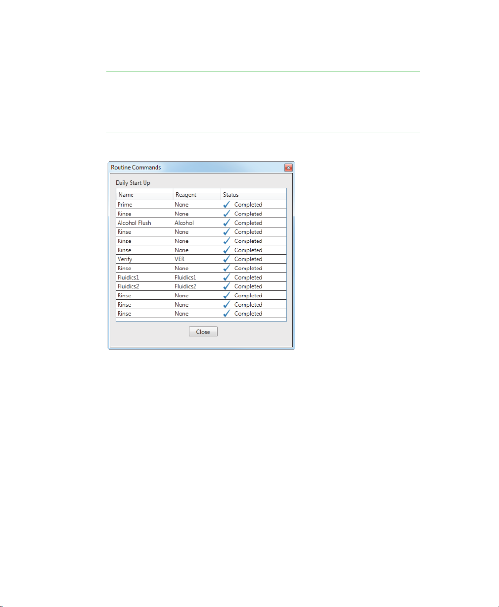
Monitoring the Routine
Progress bar The progress bar is a visual display of the
duration of the routine. The progress bar
fills from left to right as the routine is run.
When it is completely filled in, the routine
is finished running.
The following figure is an example of the Routine Commands dialog box.
User Guide | 6 3
Page 66

6 | Maintaining the MAGPIX System
Setting Up the Reagent Block
The Reagent Block section of the Maintenance view provides you with the
information you need to set up the reagent block before you run your routine.
1
2
3
4
5
6
5
6
1
7
64 | Bio-Plex Manager MP Software
Page 67

Setting Up the Reagent Block
LEGEND
1
The colored squares indicate which reservoirs to fill and specify the
appropriate liquids.
2
The wells are color-coded to correspond to the reagents specified in the
reagent block instructions. The colors match the color of the bottle
covers of the reagents.
3 Routine name
4
Instructions on which liquids and reagents are required, any preparation
required, and the amounts of the liquids and reagents to use.
5 Calibration or verification kit lot numbers
6 Reagent lot numbers
7 Description of the routine. Click the arrow to show or hide the description.
There is a diagram of the MAGPIX reagent block and well strip.
Important: The r
eservoirs and wells in the diagram correspond to those in the
MAGPIX reagent block and well strip as seen when you stand facing the
ejected plate.
When you select a maintenance routine, one or more reservoirs and wells are filled
in.
The Reagent Block section displays the lot number of the calibration kit and
verification kit curr
ently selected. It also displays the lot numbers of the reagents
that belong to the calibration and verification kits. Use this information to ensure
that you are using the correct reagents.
Important: Do not mix r
eagents from different verification kits. All of the
reagents must belong to the same lot.
If you select a different kit from the Select Kit section, the lot information in the
Reagent Block section automatically updates with the new kit information.
User Guide | 6 5
Page 68

6 | Maintaining the MAGPIX System
To set up the Reagent Block
1. Fill any colored reservoir with the indicated liquid.
2. For each colored well in the well strip, locate the appropriate calibration or
verification kit.
3. Vortex each bottle for at least 10 sec.
4. Fill the well with 6 drops of the solution from the bottle with the matching cap
color.
Calibration and Verification Kits
Calibration and verification kits are sold separately. Each calibration kit comes with
the following:
1 bottle of MAGPIX calibrator
1 calibration kit CD
1 pack of well strips
Each verification kit comes with the following:
1 bottle of MAGPIX verifier
1 bottle of MAGPIX fluidics 1
1 bottle of MAGPIX fluidics 2
1 verification kit CD
1 pack of well strips
About Kit Lot Numbers
The lot number on the box identifies the kit. Use this lot number to coordinate the
reagents with the calibration or verification values (on the CDs). The bottle for each
reagent is not identified with the lot number for the kit. Each bottle is identified with
its own lot number, but this number is different from the lot number for the kit.
66 | Bio-Plex Manager MP Software
Page 69

Calibration and Verification Kits
Important: The reagents must be used with the calibration or verification
values with the same lot number. If the values and reagents have different lot
numbers, the calibration and verification routines will fail.
Tip: When you open a new kit, continue to store the bottles in the original box
or write the lot number of the kit on each of the reagent bottles. This will make it
easier to keep track of which reagents are associated with a particular lot.
Importing the Calibration or Verification Values
The calibration kit CD and the verification kit CD contain values required to calibrate
the MAGPIX instrument and verify the results. Only one set of calibration values and
one set of verification values can be used at a time.
Best Practice
Import the calibration or verification values as soon as you open a new kit.
To import the calibration or verification values
1. Navigate to the Maintenance view.
2. In the Select Kit section, click Import Kit.
3. Load the kit by doing one of the following:
If you have the CD, place the calibration or verification kit CD in the DVD
drive and click Load from CD.
If the file is on your computer, navigate to where it is located on the
computer, select the file, and click Open.
The lot number of the calibration kit or the verification kit appears in the Reagent
Block section of the Maintenance view. Use this number to verify that you are using
the correct calibration or verification values with your reagents.
User Guide | 6 7
Page 70

6 | Maintaining the MAGPIX System
Checking the Status of the Instrument Maintenance
The Status section of the Maintenance view displays the status of the following
routines:
Calibration
Verification
Fluidics
Shut Down
The Status section displays information about the last time the routine was run. It
shows whether the routine was successfully completed or not (Passed or Failed)
and a time stamp.
68 | Bio-Plex Manager MP Software
Page 71

Responding to a Failed Routine
Status also shows the current status of the routine with the following symbols:
Symbol Description
This routine is current and up to date.
This routine is not current or the routine failed.
The Shut Down routine is in one of two states:
It has either never been run since the software was
installed.
It has not been run in the current day. This is a
reminder to run the Shut Down routine at the end of
the day before you turn the instrument off.
If the Calibration, Verification, or Fluidics routines display the hourglass icon, then
run all routines in the Recommended Routine section. Once the routine is
successfully completed, the routines in the Status pane will display as current.
If the Shut Down routine displays the hourglass icon, then run the Shut Down
r
outine before running any recommended routines.
Responding to a Failed Routine
A routine may fail due to instrument problems or user error. When failure occurs,
follow the instructions in any messages that appear and perform the recommended
routines.
User Guide | 6 9
Page 72

6 | Maintaining the MAGPIX System
Calibration Failures
If the calibration routine fails, Bio-Rad recommends you perform the following steps
in the order shown. Performing the steps in order increases the likelihood that when
you run the calibration routine again, it will succeed.
To correct a calibration failure
1. Check that the beads are in the correct wells.
2. Check that the correct calibration control values are being used.
3. Clean the sample probe.
4. Check that the waste container is not full.
5. Run the Adjust Probe Height procedure.
6. Run the recommended maintenance routine.
7. Run the Calibration and Verification routine.
If calibration fails a second time, contact Bio-Rad Technical Support.
Verification Failures
If the verification routine fails, Bio-Rad recommends you perform the following steps
in the order shown. Performing the steps in order increases the likelihood that when
you run the verification routine again, it will succeed.
To correct a verification failure
1. Check that the beads are in the correct wells.
2. Check that the correct verification and/or calibration control values are being
used.
3. Clean the sample probe.
4. Check that the waste container is not full.
5. Run the Adjust Probe Height procedure.
6. Run the recommended maintenance routine.
70 | Bio-Plex Manager MP Software
Page 73

7. Run the Calibration and Verification routine.
If verification fails a second time, contact Bio-Rad Technical Support.
Interrupting a Routine
You can interrupt a maintenance routine before it has finished, for example, if you
forgot to fill the reagent block with the necessary liquids and reagents.
To interrupt a maintenance routine
Click Stop.
Note: When you click on the Routine Log link while a routine is running, the
Routine Commands window opens. You must close the Routine Commands
window before you will be able to click Stop to interrupt the routine.
Preparing Your Instrument for Nonuse
When the MAGPIX instrument is not used for a period of time, microbes may grow
in the water reservoir and traces of liquids and reagents in the lines can crystallize.
Therefore, if you do not plan to use your instrument for 14 or more days, Bio-Rad
recommends you prepare your instrument for a period of nonuse. Taking these
steps before the instrument is idle will minimize the maintenance required when you
resume using it.
Interrupting a Routine
To prepare your instrument for nonuse
1. Run the Prepare for Storage maintenance routine.
2. Remove the drive fluid container from the instrument.
3. Remove and empty the waste container.
4. Empty any liquids from the reagent block. Wash and dry the reagent block.
5. Empty any liquids from the well strip.
User Guide | 7 1
Page 74

6 | Maintaining the MAGPIX System
Adjusting the Probe Height
The probe must be calibrated in order to work correctly with the different plate
types. Adjust the probe height in the following situations:
After you set up the MAGPIX instrument and the computer, you must first
adjust the probe height before you run any protocols.
After you remove and clean the probe, you must adjust the probe height.
If you experience sample problems, adjusting the probe height may resolve
these errors.
To adjust the probe height
1. From the Maintenance view, click Adjust Probe Height.
The Adjust Probe Height dialog box appears.
2. Empty the reagent block and the well strip.
The rightmost reservoir in the reagent block and the rightmost well in the well
strip must be empty.
3. Insert the MCV plate, well strip, and reagent block.
4. Click Adjust Probe Height.
When the calibration is completed, a dialog box appears confirming that the
adjust probe height procedure is completed.
5. Click OK.
Weekly Maintenance
Clean the sample probe once a week to keep it free of any debris. Whenever you
remove the sample probe from the probe assembly, you must recalibrate the probe
before you read another plate. Therefore, cleaning the sample probe must always
be followed up with running the Adjust Probe Height maintenance routine.
72 | Bio-Plex Manager MP Software
Page 75

Cleaning the Sample Probe
To clean the sample probe
1. Turn off the MAGPIX instrument and unplug the power cord.
2. Remove the sample probe.
3. Use either or both methods to clean the sample probe:
Bath sonicator — place the tip of the sample probe in the bath sonicator
for 2–5 min.
10 ml syringe — force distilled water through the tip of the sample probe to
its large end.
4. Replace the sample probe. Screw the black fitting on top of the sample probe
until it clicks.
5. From the Maintenance view, run the Adjust Probe Height procedure.
MAGPIX Maintenance
Within the first year of use, Bio-Rad recommends that you perform the 6-month and
12-month maintenance. The maintenance kits are:
MAGPIX Maintenance
Bio-Plex
filters and replaces the syringe seals (catalog
Bio-Plex MAGPIX 12-Month Preventive Maintenance Kit — replaces the
sample probe tube and the drive fluid filter (catalog
®
MAGPIX™ 6-Month Preventive Maintenance Kit — cleans the air
#171-012010).
#171-012012).
User Guide | 7 3
Page 76

6 | Maintaining the MAGPIX System
74 | Bio-Plex Manager MP Software
Page 77

7 Maintenance Routines
The maintenance routines keep the MAGPIX instrument in good working order and
operating according to the manufacturer’s specifications. Bio-Rad recommends
that you run the recommended routine at the start of each day to minimize having to
keep track of running the correct routines at the right time. In addition to running the
recommended routine, you can run any of the maintenance routines as necessary.
Calibration and Verification Routine
Description of Routine
Calibration normalizes the operation of the MAGPIX analyzer when it acquires data.
Once calibrated, the values remain until you recalibrate. Verification verifies the
operation of the MAGPIX analyzer.
When to Run this Routine
Bio-Plex Manager™ MP software adds calibration and verification to the Daily Start
Up routine once a week in accordance with the manufacturer’s recommendation.
Therefore, if you run the Daily Start Up routine daily, you will be running the
Calibration and Verification routine as recommended.
In addition, recalibrate the system if the any of the following is true:
The delta calibration temperature exceeds ±5ºC.
The instrument has been moved.
The instrument undergoes hardware maintenance, for example, a part
replacement.
User Guide | 7 5
Page 78

7 | Maintenance Routines
Estimated Run Time
10 minutes
To Run the Calibration and Verification Routine
Before you run the Calibration and Verification routine, you must import the
calibration and verification kit information. For more information, see
Verification Kits on page 66.
1. Navigate to the Maintenance view.
2. In the Select Routine section, select Calibration and Verification from the
Additional Routines dropdown list.
3. Add 5 ml 70% isopropanol to the appropriate reservoir in the reagent block.
4. Vortex CAL, VER, Fluidics1, and Fluidics2 each for 10 sec.
5. Add 6 drops each of CAL, VER, Fluidics1, and Fluidics2 to the indicated wells.
6. Click Start.
Calibration and
76 | Bio-Plex Manager MP Software
Page 79

Clear Bubbles Routine
Description of Routine
The Clear Bubbles routine performs a series of fluidics operations to force out air
bubbles that may be trapped in the cuvette.
When to Run this Routine
If you suspect there is air in the MAGPIX system, run the Clear Bubbles routine.
Estimated Run Time
3 minutes
To Run the Clear Bubbles Routine
1. Navigate to the Maintenance view.
2. In the Select Routine section, select Clear Bubbles from the Additional
Routines dropdown list.
3. Add 5 ml distilled or deionized water and 5 ml 70% isopropanol to the
appropriate reservoirs in the reagent block.
Clear Bubbles Routine
4. Click Start.
User Guide | 7 7
Page 80

7 | Maintenance Routines
Daily Start Up Routine
Description of Routine
Daily Start Up prepares your instrument for daily use. It runs different routines
depending on the state of the instrument. Daily Start Up may include the Calibration
and Verification, Verification, and Wake From Storage routines.
When to Run this Routine
Run Daily Start Up each day you use the instrument before you run any protocols.
You do not need to keep track of the calibration and verification status if you run this
routine at the start of each day.
Estimated Run Time
4–12 minutes
To Run the Daily Start Up Routine
1. Navigate to the Maintenance view.
2. In the Select Routine section, select Daily Start Up.
3. Fill the reservoirs and the well strip with the solutions indicated in the Reagent
Block diagram.
4. Click Start.
78 | Bio-Plex Manager MP Software
Page 81

Enhanced Maintenance Routine
Description of Routine
The Enhanced Maintenance routine clears any bubbles from the system and clears
any clogs from the probe and fluidics.
When to Run this Routine
This routine is recommended when a low bead count occurs during a protocol run
or when calibration or verification fails.
Estimated Run Time
14 minutes
Before Running the Routine
Before you run the Enhanced Maintenance Routine, Bio-Rad recommends that you
check the following:
1. Check that the correct calibration and control lots are being used.
2. Clean the sample probe.
Enhanced Maintenance Routine
3. Check that the waste container is not full.
4. Run the Adjust Probe Height procedure.
To Run the Enhanced Maintenance Routine
1. Navigate to the Maintenance view.
2. In the Select Routine section, select Enhanced Maintenance.
3. Add 5 ml distilled or deionized water, 5 ml 70% isopropanol, and 5 ml 0.1N
NaOH to the appropriate reservoirs in the reagent block.
4. Click Start.
User Guide | 7 9
Page 82

7 | Maintenance Routines
Fluidics Preparation Routine
Description of Routine
The Fluidics Preparation routine prepares the fluidics system for daily use.
When to Run this Routine
Run the Fluidics Preparation routine when you replace an empty drive fluid
container or if the drive fluid line is not aspirating drive fluid because the line has
become dislodged.
Estimated Run Time
2 minutes
To Run the Fluidics Preparation Routine
1. Navigate to the Maintenance view.
2. In the Select Routine section, select Fluidics Preparation from the Additional
Routines dropdown list.
3. Add 5 ml 70% isopropanol to the appropriate reservoir in the reagent block.
4. Click Start.
80 | Bio-Plex Manager MP Software
Page 83

Prepare for Storage Routine
Description of Routine
The Prepare for Storage routine clears all fluids from the instrument.
When to Run this Routine
Run the Prepare for Storage routine if you will not be using the instrument for more
than two weeks or before you ship the instrument to Bio-Rad.
Estimated Run Time
6 minutes
To Run the Prepare for Storage Routine
1. Navigate to the Maintenance view.
2. In the Select Routine section, select Prepare for Storage from the Additional
Routines dropdown list.
3. Add 5 ml distilled or deionized water, 5 ml 0.1N NaOH, and 5 ml 10% bleach to
the appropriate reservoirs in the reagent block.
Prepare for Storage Routine
4. Click Start.
User Guide | 8 1
Page 84

7 | Maintenance Routines
Prime Routine
Description of Routine
The Prime routine primes the fluidics system by forcing drive fluid through the
fluidics lines.
When to Run this Routine
If the Unpack MAGPIX routine fails during the initial instrument set up, then run the
Prime routine.
Estimated Run Time
1 minute
To Run the Prime Routine
1. Navigate to the Maintenance view.
2. In the Select Routine section, select Prime from the Additional Routines
dropdown list.
3. Click Start.
82 | Bio-Plex Manager MP Software
Page 85

Shut Down Routine
Description of Routine
The Shut Down routine cleans the fluidics lines and prevents a buildup of debris
within the system.
When to Run the Routine
Bio-Rad recommends that you run the Shut Down routine at the end of each day
that you use the instrument. Refer to the Shut Down entry in the status section in
the Maintenance view to determine whether the Shut Down has been run that day.
Estimated Run Time
2 minutes
To Run the Shut Down Routine
1. Navigate to the Maintenance view.
2. In the Select Routine section, select Shut Down.
3. Add 5 ml distilled or deionized water and 5 ml bleach to the appropriate
reservoirs in the reagent block.
Shut Down Routine
4. Click Start.
User Guide | 8 3
Page 86

7 | Maintenance Routines
Unclog Routine
Description of Routine
This procedure performs a series of fluidics operations to remove possible
obstructions from the fluidics lines.
When to Run this Routine
If you suspect there is an obstruction in the MAGPIX system, run the Unclog routine.
Estimated Run Time
2 minutes
To Run the Unclog Routine
1. Navigate to the Maintenance view.
2. In the Select Routine section, select Unclog from the Additional Routines
dropdown list.
3. Add 5 ml distilled or deionized water and 5 ml 0.1N NaOH to the appropriate
reservoirs in the reagent block.
4. Insert the plate in the microplate platform and click Start.
84 | Bio-Plex Manager MP Software
Page 87

Verification Routine
Description of Routine
The Verification routine ensures that the calibration settings are valid and ensures
that well-to-well cross talk does not occur.
When to Run this Routine
Run the Verification routine when its status in the Maintenance view is not up to
date. Bio-Plex
accordance with the manufacturer’s recommendation. Therefore, if you run the Daily
Start Up routine daily, you will be running the Verification routine as recommended.
Estimated Run Time
4 minutes
To Run the Verification Routine
Before you run the Verification routine, you must import the verification kit
information. For more information, see
1. Navigate to the Maintenance view.
Manager MP adds verification to the Daily Start Up routine in
Verification Routine
Calibration and Verification Kits on page 66.
2. In the Select Routine section, select Verification from the Additional Routines
dropdown list.
3. Add 5 ml 70% isopropanol to the appropriate reservoir in the reagent block.
4. Vortex VER, Fluidics1, and Fluidics2 each for 10 sec.
5. Add 6 drops each of CAL, VER, Fluidics1, and Fluidics2 to the indicated wells.
6. Click Start.
User Guide | 8 5
Page 88

7 | Maintenance Routines
Wake from Storage Routine
Description of Routine
The Wake from Storage routine prepares the instrument to be used after it has been
idle for a long period of time.
When to Run this Routine
Run the Wake from Storage routine if the instrument has been idle for 2 weeks or
longer or if it has been prepared for storage.
Bio-Plex Manager MP adds Wake From Storage to the Daily Start Up routine if it
detects that the instrument has been idle for 2 weeks or longer. Therefore, if you run
the Daily Start Up routine daily, you will be running this routine as recommended.
Estimated Run Time
2 minutes
To Run the Wake From Storage Routine
1. Navigate to the Maintenance view.
2. In the Select Routine section, select Wake From Storage from the Additional
Routines dropdown list.
3. Add 5 ml distilled or deionized water and 5 ml 70% isopropanol to the
appropriate reservoirs in the reagent block.
4. Click Start.
86 | Bio-Plex Manager MP Software
Page 89

Wash Between Plates Routine
Description of Routine
The Wash Between Plates routine performs a series of fluidics operations to prevent
traces of sample or other debris from collecting inside the Bio-Plex® suspension
array system.
When to Run this Routine
Bio-Rad recommends that you wash the fluidics lines after each plate reading.
Note: In the Run Settings dialog box, the default is to run the Wash Between
Plates routine after the reading.
Estimated Run Time
6 minutes
To Run the Wash Between Plates Routine
1. Navigate to the Maintenance view.
2. In the Select Routine section, select Wash Between Plates from the Additional
Routines dropdown list.
Wash Between Plates Routine
3. Add 5 ml distilled or deionized water, 5 ml 70% isopropanol, and 5 ml 0.1N
NaOH to the appropriate reservoirs in the reagent block.
4. Click Start.
User Guide | 8 7
Page 90

7 | Maintenance Routines
88 | Bio-Plex Manager MP Software
Page 91

A License Activation
To have access to all of the features of Bio-Plex Manager™ MP software, you must
activate the product with a valid product license. You will need a separate license
for each computer on which you install Bio-Plex
Note: If you purchased a new MAGPIX instrument, the computer included with
the instrument comes with the software already activated. Therefore, you can
skip this step.
Activating the Bio-Plex Manager MP License
You can activate the product either online (if you have access to the Internet) or
through Technical Support (if you do not have Internet access).
Note: To activate your license, you will need the product activation code,
which can be found in the Bio-Plex
Manager MP CD folder.
Activating the License Online
Follow the procedure below if the computer on which Bio-Plex Manager MP is
installed has an Internet connection. With this method, the software uses your
activation code to automatically activate your software.
Manager MP.
To activate Bio-Plex Manager MP online
1. Start the Bio-Plex Manager MP software.
User Guide | 8 9
Page 92

A | License Activation
2. If the product license has not been activated, the Product Activation Required
window appears.
3. Select Activate Bio-Plex Manager MP Online and click Continue.
4. Enter your activation code in the text box and click Activate.
Note: The activation code can be found in the CD folder.
90 | Bio-Plex Manager MP Software
Page 93

Activating the License through Technical Support
The Activation Successful window appears confirming that the software has
been activated.
5. Click OK to exit the activation software and start Bio-Plex Manager MP.
Activating the License through Technical Support
If the computer on which Bio-Plex Manager MP is installed does not have an
Internet connection, you can request a product license from Bio-Rad Technical
Support to activate the software. This is a two-phase process:
1. Generate a credentials file and email it to Technical Support.
Technical Support uses the credentials file to generate a license and emails the
file back to you.
2. Use the license file to activate your software.
The procedures that follow describe this two-phase process.
User Guide | 9 1
Page 94

A | License Activation
Generating the Credentials File
To generate the credentials file
1. Start the Bio-Plex Manager MP software.
2. If the product license has not been activated, the Product Activation Required
window appears.
3. Select Activate Bio-Plex Manager MP through Technical Support and click
Continue.
92 | Bio-Plex Manager MP Software
Page 95

Activating the License through Technical Support
4. Select Send credentials to Technical Support and click Continue.
5. Enter your activation code in the text box and click Save.
Note: The activation code can be found in the CD folder.
6. In the Save Licensing Credentials to a File dialog box, enter the name of the file
and click Save.
User Guide | 9 3
Page 96

A | License Activation
The File Successfully Saved window appears with instructions on how to send
the credentials file to Technical Support.
7. Move the credentials file to a computer where you can send email, and email
the file to Bio-Rad Technical Support (LSG_Software_Act@bio-rad.com).
Activating the Software with a License File
Technical Support will generate a file with the license and email the file to you. When
you receive the email, transfer the file to the computer where Bio-Plex Manager MP
is installed. The file can be copied to a local har
d drive, flash drive, or network drive.
94 | Bio-Plex Manager MP Software
Page 97

Activating the License through Technical Support
To activate Bio-Plex Manager MP with the license file
1. Start the Bio-Plex Manager MP software.
2. In the Product Activation Required window, select Activate Bio-Plex Manager
thr
ough Technical Support and click Continue.
3. Select “Import license file and activate product” and click Continue.
User Guide | 9 5
Page 98

A | License Activation
4. Click Activate.
5. Navigate to where the license file is located, select the file, and click Open.
The Activation Successful window appears confirming that the software has
been activated.
6. Click OK to exit the activation software and start Bio-Plex Manager MP.
96 | Bio-Plex Manager MP Software
Page 99

Deactivating the Bio-Plex Manager MP License
Deactivating the Bio-Plex Manager MP License
You may want to deactivate the Bio-Plex Manager MP license for one of the
following reasons:
You want to move the license from one computer to another.
This can occur, for example, if you are replacing your computer. You must first
deactivate the license fr
second computer.
You want to remove the license from the computer.
om the first computer and then activate it on the
Deactivating the License Online
To deactivate Bio-Plex Manager MP online
1. Start Bio-Plex Manager MP.
2. From the Help menu, click Manage License.
3. Select Deactivate Bio-Plex Manager MP Online and click Continue.
User Guide | 9 7
Page 100

A | License Activation
4. Enter your activation code and click Deactivate.
Note: The Activation Code field will be populated with the activation code.
If the field is empty
The Deactivation Successful window appears confirming the software has been
deactivated.
, you can find the activation code in the CD folder.
5. Click Exit.
98 | Bio-Plex Manager MP Software
 Loading...