


 Loading...
Operating Manual
APT.line™ VDL (E2.1)
Vacuum drying ovens for flammable solvents
with microprocessor program controller RD3
Model |
Art. No. |
VDL 23 (E2.1) |
9030-0038, 9130-0038 |
VDL 53 (E2.1) |
9030-0039, 9130-0039 |
VDL 115 (E2.1) |
9030-0040, 9130-0040 |
BINDER GmbH
Address |
Post office box 102 |
|
|
D-78502 Tuttlingen |
|
Tel. |
+49 |
7462 2005 0 |
Fax |
+49 |
7462 2005 100 |
Internet |
http://www.binder-world.com |
|
info@binder-world.com |
||
Service Hotline |
+49 |
7462 2005 555 |
Service Fax |
+49 |
7462 2005 93 555 |
Service E-Mail |
service@binder-world.com |
|
Service Hotline USA |
+1 866 885 9794 or +1 631 224 4340 x3 |
|
Service Hotline Asia Pacific |
+852 390 705 04 or +852 390 705 03 |
|
Service Hotline Russia and CIS |
+7 495 98815 16 |
|
|
|
|
Issue 04/2014 |
|
Art. No. 7001-0124 |
|
|
|

EC – Declaration of Conformity
EG – KONFORMITÄTSERKLÄRUNG
EC - DECLARATION OF CONFORMITY
CE - DECLARATION DE CONFORMITE
Anbieter / Supplier / Fournisseur: BINDER GmbH
Anschrift / Address / Adresse: Im Mittleren Ösch 5, D-78532 Tuttlingen
Produkt / Product / Produit: Vakuumtrockenschränke für entflammbare Lösungsmittel Vacuum drying ovens for flammable solvents
Etuves de séchage à vide pour les solvants inflammables
Typenbezeichnung / Type / Type: VDL 23, VDL 53, VDL 115
Die oben beschriebenen Produkte sind konform mit folgenden EG-Richtlinien: The products described above are in conformity with the following EC guidelines: Les produits décrits ci-dessus sont conformes aux directives CE suivantes:
Niederspannungsrichtlinie 2006/95/EG
Low voltage directive 2006/95/EC
Directive basse tension 2006/95/CE
EMV-Richtlinie 2004/108/EG
EMC Directive 2004/108/EC
Directive CEM 2004/108/CE
ATEX-Richtlinie 94/9/EG
ATEX Directive 94/9/EC
Directive ATEX 94/9/CE
Richtlinie 2006/95/EG des Europäischen Parlaments und des Rates vom 12. Dezember 2006 zur Angleichung der Rechtsvorschriften der Mitgliedstaaten betreffend elektrische Betriebsmittel zur Verwendung innerhalb bestimmter Spannungsgrenzen
Council Directive 2006/95/EC of 12 December 2006 on the harmonization of the laws of Member States relating to electrical equipment designed for use within certain voltage limits
Directive 2006/95/CE du Parlement Européen et du Conseil du 12 décembre 2006 concernant le rapprochement des législations des États membres relatives au matériel électrique destiné à être employé dans certaines limites de tension
Richtlinie 2004/108/EG des Europäischen Parlaments und des Rates vom 15. Dezember 2004 zur Angleichung der Rechtsvorschriften der Mitgliedstaaten über die elektromagnetische Verträglichkeit und zur Aufhebung der Richtlinie 89/336/EWG.
Directive 2004/108/EC of the European Parliament and of the Council of 15 December 2004 on the approximation of the laws of the Member States relating to electromagnetic compatibility and repealing Directive 98/336/EEC.
Directive 2004/108/CE du Parlement Européen et du Conseil du 15 décembre 2004 relative au rapprochement des législations des États membres concernant la compatibilité électromagnétique et abrogeant le directive 98/336/CEE.
Richtlinie 94/9/EG des Europäischen Parlaments und des Rates zur Angleichung der Rechtsvorschriften der Mitgliedstaaten für Geräte und Schutzsysteme zur bestimmungsgemäßen Verwendung in explosionsgefährdeten Bereichen.
Directive 94/9/EC of the European parliament and the council of 23 March 1994 on the approximation of the laws of the Member States concerning equipment and protective systems intended for use in potentially explosive atmospheres
Directive 94/9/CE du parlement européen et du conseil du 23 mars 1994 concernant le rapprochement des législations des États membres pour les appareils et les systèmes de protection destinés à être utilisés en atmosphères explosibles.
1 / 3
VDL (E2.1) 04/2014 |
page 2/107 |

Die oben beschriebenen Produkte tragen entsprechend die Kennzeichnung CE. The products described above, corresponding to this, bear the CE-mark.
Les produits décrits ci-dessus, en correspondance, portent l’indication CE.
Die Ex-Klassifikation des Geräteinnenraums nach ATEX Richtlinie 94/9/EG ist : The Ex classification of the inner chamber according to ATEX Directive 94/9/EC is : La classification Ex de la chambre intérieure selon la Directive 94/9/CE ATEX est :
II -3G IIB T3-T1 Gc X
Die Temperaturklasse des Geräteinnenraums nach EN 60079-14 ist abhängig von der Einstellung des Temperaturwählbegrenzers und kann T1, T2 oder T3 sein. Die Temperaturklasse des Gesamtgerätes entspricht der Temperaturklasse des Innenraums.
The temperature class of the inner chamber acc. to EN 60079-14 depends on the setting of the temperature safety device and can be T1, T2 or T3. The temperature class of the entire unit is equal to the temperature class of the inner chamber.
La classe de température de la chambre intérieure selon EN 60079-14 dépend du réglage de la sécurité de surchauffe. Elle peut être T1, T2 ou T3. La classe de température de l’appareil entier est égale à celle de la chambre intérieure.
Die oben beschriebenen Produkte sind konform mit folgenden harmonisierten Normen: The products described above are in conformity with the following harmonized standards: Les produits décrits ci-dessus sont conformes aux normes harmonisées suivantes:
Sicherheit / safety / sécurité:
EN 61010-1:2010 Sicherheitsbestimmungen für elektrische Mess-, Steuer-, Regelund Laborgeräte
– Teil 1: Allgemeine Anforderungen (DIN EN 61010-1:2011, VDE 411-1:2011)
Safety requirements for electrical equipment for measurement, control, and laboratory use – Part 1: General requirements (IEC 61010-1:2010, BS EN 61010- 1:2010)
Règles de sécurité pour appareils électriques de mesurage, de régulation et de laboratoire – Partie 1: Prescriptions générales (CEI 61010-1:2010, NF EN 61010:2011)
EN 61010-2-010:2003 Sicherheitsbestimmungen für elektrische Meß-, Steuer-, Regelund Laborgeräte
– Teil 2-010: Besondere Anforderungen an Laborgeräte für das Erhitzen von Stoffen (DIN EN 61010-2-010:2004)
Safety requirements for electrical equipment for measurement, control, and laboratory use – Part 2-010: Particular requirements for laboratory equipment for the heating of materials (IEC 61010-2-10:2005, BS EN 61010-2-10:2003)
Règles de sécurité pour appareils électriques de mesurage, de régulation et de laboratoire – Partie 2-010 : Prescriptions particulières pour appareils de laboratoire utilisés pour l’échauffement des matières (CEI 61010-2-10:2003, NF EN 61010-2-10:2005)
EMV / EMC / CEM:
EN 61326-1:2013 Elektrische Mess-, Steuer-, Regelund Laborgeräte - EMV-Anforderungen - Teil 1: Allgemeine Anforderungen (DIN EN 61326-1:2013, VDE 0813-20-1:2013)
Electrical equipment for measurement, control and laboratory use - EMC requirements - Part 1: General requirements (IEC 61326-1:2012, BS EN 61326- 1:2013)
Matériel électrique de mesure, de commande et de laboratoire - Exigences relatives à la CEM - Partie 1: Exigences générales (CEI 61326-1:2012, NF EN 61326- 1:2013.)
2 / 3
VDL (E2.1) 04/2014 |
page 3/107 |

Explosionsschutz / Explosion protection / Protection contre les explosions
EN 1127-1:2011 |
Explosionsfähige Atmosphären – Explosionsschutz – Teil 1: Grundlagen und |
|
Methodik (DIN EN 1127-1:2011) |
|
Explosive atmospheres. Explosion prevention and protection. Part 1: Basic |
|
concepts and methodology (BS EN 1127-1:2011) |
|
Atmosphères explosives. Prévention de l’explosion et protection contre |
|
l’explosion. Partie 1: Notions fondamentales et méthodologie (NF EN 1127- |
|
1:2011) |
EN 13463-1:2009 |
Nicht-elektrische Geräte für den Einsatz in explosionsgefährdeten Bereichen – |
|
Teil 1: Grundlagen und Anforderungen (DIN EN 13463-1:2009) |
Non-electrical equipment for use in potentially explosive atmospheres – Part 1: Basic method and requirements
Appareils non électriques destines à être utilisés en atmosphères explosibles
– Partie 1 : Prescriptions et méthodologie
Zusätzlich für Geräte mit Option „Zusätzlicher Messkanal für digitale Objekttemperaturanzeige mit flexiblem Pt 100 Temperaturfühler“ :
In addition for units with option “Additional measuring channel for digital object temperature display with flexible Pt 100 temperature sensor” :
En outre, pour les appareils avec l’option « Canal de mesure additionnel pour l’affichage de la température de l’échantillon avec sonde de température flexible Pt100 » :
EN 60079-11:2012
Section 5.7
Explosionsfähige Atmosphäre – Teil 11: Geräteschutz durch Eigensicherheit "i" (DIN EN 60079-11:2012, VDE 0170-7:2012). Abschnitt 5.7 Einfache elektrische Betriebsmittel
Explosive atmospheres – Part 11: Equipment protection by intrinsic safety "i" (BS EN 60079-11:2012, IEC 60079-11:2011 + Cor.:2012). Section 5.7 Simple apparatus
Atmosphères explosives – Partie 11: protection de l'équipement par sécurité intrinsèque "i" (NF EN 60079-11:2012). 5.7 Matériel simple
D-78532 Tuttlingen, 24.04.2014
BINDER GmbH
P. M. Binder |
J. Bollaender |
Geschäftsführender Gesellschafter |
Leiter F & E |
Managing Director |
Director R & D |
Directeur général |
Chef de service R&D |
3 / 3
VDL (E2.1) 04/2014 |
page 4/107 |

TÜV Certificate
VDL (E2.1) 04/2014 |
page 5/107 |

Product registration
VDL (E2.1) 04/2014 |
page 6/107 |

Contents
EC – Declaration of Conformity..................................................................................................................... |
2 |
||
TÜV Certificate .............................................................................................................................................. |
5 |
||
Product registration ....................................................................................................................................... |
6 |
||
1. |
SAFETY................................................................................................................ |
10 |
|
1.1 |
Legal considerations ......................................................................................................................... |
10 |
|
1.2 |
Structure of the safety instructions.................................................................................................... |
10 |
|
|
1.2.1 |
Signal word panel.................................................................................................................... |
10 |
|
1.2.2 |
Safety alert symbol.................................................................................................................. |
11 |
|
1.2.3 |
Pictograms .............................................................................................................................. |
11 |
|
1.2.4 |
Word message panel structure............................................................................................... |
12 |
1.3 |
Localization / position of safety labels on the unit ............................................................................. |
12 |
|
1.4 |
Type plate.......................................................................................................................................... |
13 |
|
1.5 |
General safety instructions on installing and operating the vacuum drying oven.............................. |
14 |
|
|
1.5.1 |
Safety instructions on installation and ambient conditions...................................................... |
15 |
|
1.5.2 |
Safety instructions on vacuum supply..................................................................................... |
15 |
|
1.5.3 |
Safety instructions on the charging material ........................................................................... |
17 |
|
1.5.4 |
Safety instructions on operating the vacuum drying oven....................................................... |
18 |
1.6 |
Intended use...................................................................................................................................... |
21 |
|
|
1.6.1 |
Operation log........................................................................................................................... |
21 |
2. |
DESCRIPTION OF THE EQUIPMENT ................................................................. |
23 |
|
2.1 |
Safety equipment .............................................................................................................................. |
24 |
|
2.2 |
Overview of the oven......................................................................................................................... |
25 |
|
2.3 |
VDL control panel.............................................................................................................................. |
26 |
|
2.4 |
Connections at the rear of the unit .................................................................................................... |
27 |
|
2.5 |
“Temperature setting” information panel (ignition temperature vs. drying temperature).................. |
28 |
|
2.6 |
Overview of the zone classification of the ovens............................................................................... |
29 |
|
3.COMPLETENESS OF DELIVERY, TRANSPORTATION, STORAGE, AND
|
INSTALLATION.................................................................................................... |
31 |
|
3.1 |
Unpacking, and checking equipment and completeness of delivery................................................. |
31 |
|
3.2 |
Guidelines for safe lifting and transportation..................................................................................... |
32 |
|
3.3 |
Storage.............................................................................................................................................. |
32 |
|
3.4 |
Location of installation and ambient conditions................................................................................. |
32 |
|
4. |
INSTALLATION AND CONNECTIONS................................................................ |
34 |
|
4.1 |
Vacuum expansion racks .................................................................................................................. |
34 |
|
4.2 |
Vacuum connection........................................................................................................................... |
35 |
|
|
4.2.1 Notes regarding use of vacuum pumps of other manufacturers............................................. |
37 |
|
4.3 |
Inert gas connection.......................................................................................................................... |
37 |
|
4.4 |
Compressed air / inert gas connection for sweeping the area for electrical equipment.................... |
38 |
|
4.5 |
Electrical connection ......................................................................................................................... |
39 |
|
5. |
START UP ............................................................................................................ |
40 |
|
5.1 |
Settings at the RD3 program controller............................................................................................. |
40 |
|
5.2 |
General indications............................................................................................................................ |
41 |
|
6. |
FIXED VALUE ENTRY MODE ............................................................................. |
43 |
|
7. |
WEEK PROGRAM EDITOR ................................................................................. |
45 |
|
7.1 |
Program table template for the Week Program Editor...................................................................... |
47 |
|
7.2 |
Programming example of the Week program editor......................................................................... |
48 |
|
|
7.2.1 |
Desired time function .............................................................................................................. |
48 |
|
7.2.2 |
Proceeding overview............................................................................................................... |
48 |
|
7.2.3 |
Proceeding in detail................................................................................................................. |
49 |
|
|
||
VDL (E2.1) 04/2014 |
page 7/107 |
||

8. |
PROGRAM EDITOR............................................................................................. |
|
54 |
|
8.1 |
Selecting between set-point ramp and set-point step ....................................................................... |
|
54 |
|
8.1.1 Programming with setting “Ramp” (default setting) ................................................................ |
|
54 |
||
8.1.2 Programming with setting “step” ............................................................................................. |
|
57 |
||
8.1.3 General notes on programming temperature transitions ........................................................ |
|
58 |
||
8.2 |
Set-point entry for program operation ............................................................................................... |
|
58 |
|
8.3 |
Program table template..................................................................................................................... |
|
61 |
|
8.4 |
Deleting a program section ............................................................................................................... |
|
62 |
|
9. |
PROGRAM START LEVEL.................................................................................. |
|
63 |
|
10. |
USER LEVEL ....................................................................................................... |
|
66 |
|
11. |
PERFORMANCE IN CASE OF FAILURES.......................................................... |
|
72 |
|
11.1 |
Performance after power failures ...................................................................................................... |
|
72 |
|
11.2 |
Alarm messages ............................................................................................................................... |
|
72 |
|
12. |
SAFETY DEVICE CLASS 2 (DIN 12880)............................................................. |
|
72 |
|
13. |
REFERENCE MEASUREMENTS. CHECKING THE TEMPERATURE IN THE |
|
||
|
INNER CHAMBER................................................................................................ |
|
74 |
|
14. |
COMMISSIONING THE VACUUM ....................................................................... |
|
74 |
|
14.1 |
Evacuation......................................................................................................................................... |
|
75 |
|
14.2 |
Breaking the vacuum (flooding with ambient air) .............................................................................. |
|
75 |
|
14.3 |
Operation with inert gas .................................................................................................................... |
|
75 |
|
15. |
OPTIONS.............................................................................................................. |
|
76 |
|
15.1 |
ATEX connection kits for vacuum pumps VP4 or VP5 (option) ........................................................ |
|
76 |
|
15.2 |
Vacuum module empty (without pump) (option) ............................................................................... |
|
77 |
|
15.3 |
Vacuum module with chemical membrane pump VP4 or VP5 (option) ............................................ |
|
79 |
|
15.4 |
Additional measuring channel for digital object temperature display with flexible Pt 100 temperature |
|||
|
sensor (option) .................................................................................................................................. |
|
82 |
|
15.5 |
Measuring access port vacuum 9 poles (option)............................................................................... |
|
84 |
|
15.6 |
Communication software APT-COM™ 3 DataControlSystem (option)............................................. |
|
84 |
|
16. |
MAINTENANCE, CLEANING, AND SERVICE..................................................... |
|
85 |
|
16.1 |
Maintenance intervals, service .......................................................................................................... |
|
85 |
|
16.2 |
Cleaning and decontamination.......................................................................................................... |
|
86 |
|
16.2.1 |
Cleaning.................................................................................................................................. |
|
86 |
|
16.2.2 |
Decontamination ..................................................................................................................... |
|
87 |
|
16.3 |
Sending the unit back to BINDER GmbH.......................................................................................... |
|
89 |
|
17. |
DISPOSAL............................................................................................................ |
|
89 |
|
17.1 |
Disposal of the transport packing...................................................................................................... |
|
89 |
|
17.2 |
Decommissioning.............................................................................................................................. |
|
90 |
|
17.3 |
Disposal of the unit in the Federal Republic of Germany.................................................................. |
|
90 |
|
17.4 |
Disposal of the unit in the member states of the EC except for the Federal Republic of Germany |
..91 |
||
17.5 |
Disposal of the unit in non-member states of the EC........................................................................ |
|
93 |
|
18. |
TROUBLESHOOTING ......................................................................................... |
|
93 |
|
19. |
TECHNICAL DESCRIPTION................................................................................ |
|
95 |
|
19.1 |
Factory calibration and adjustment ................................................................................................... |
|
95 |
|
19.2 |
VDL technical data ............................................................................................................................ |
|
95 |
|
19.3 |
Equipment and Options..................................................................................................................... |
|
97 |
|
|
|
|||
VDL (E2.1) 04/2014 |
page 8/107 |
|||

19.4 |
Spare parts........................................................................................................................................ |
98 |
19.5 |
Dimensions VDL 23........................................................................................................................... |
99 |
19.6 |
Dimensions VDL 53......................................................................................................................... |
100 |
19.7 |
Dimensions VDL 115....................................................................................................................... |
101 |
20. |
CONTAMINATION CLEARANCE CERTIFICATE .............................................. |
102 |
20.1 |
For units located outside North America and Central America ....................................................... |
102 |
20.2 |
For units in North America and Central America............................................................................. |
105 |
VDL (E2.1) 04/2014 |
page 9/107 |

Dear customer,
For the correct operation of the program controlled vacuum drying oven VDL, it is important that you read this operating manual completely and carefully and observe all instructions as indicated. Failure to read, understand and follow the instructions may result in personal injury. It can also lead to damage to the unit and/or poor equipment performance.
1.Safety
This operating manual is part of the components of delivery. Always keep it handy for reference. The device should only be operated by laboratory personnel especially trained for this purpose and familiar with all precautionary measures required for working in a laboratory. Observe the national regulations on minimum age of laboratory personnel. To avoid injuries and damage observe the safety instructions of the operating manual.
 WARNING
Failure to observe the safety instructions.
Serious injuries and unit damage.
Observe the safety instructions in this operating manual.
Carefully read the complete operating instructions of the VDL vacuum drying oven.
1.1Legal considerations
This operating manual is for informational purposes only. It contains information for installing, start-up, operation and maintenance of the product. Note: the contents and the product described are subject to change without notice.
Understanding and observing the instructions in this operating manual are prerequisites for hazard-free use and safety during operation and maintenance. In no event shall BINDER be held liable for any damages, direct or incidental arising out of or related to the use of this manual.
This operating manual cannot cover all conceivable applications. If you would like additional information, or if special problems arise that are not sufficiently addressed in this manual, please ask your dealer or contact us directly by phone at the number located on page one of this manual
Furthermore, we emphasize that the contents of this operating manual are not part of an earlier or existing agreement, description, or legal relationship, nor do they modify such a relationship. All obligations on the part of BINDER derive from the respective purchase contract, which also contains the entire and exclusively valid statement of warranty administration. The statements in this manual neither augment nor restrict the contractual warranty provisions.
Have repairs performed only by experts authorized by BINDER. Repaired units must comply with the quality standard specified by BINDER.
1.2Structure of the safety instructions
In this operating manual, the following safety definitions and symbols indicate dangerous situations following the harmonization of ISO 3864-2 and ANSI Z535.6.
1.2.1 Signal word panel
Depending on the probability of serious consequences, potential dangers are identified with a signal word, the corresponding safety color, and if appropriate, the safety alert symbol.
VDL (E2.1) 04/2014 |
page 10/107 |
 DANGER
Indicates an imminently hazardous situation that, if not avoided, will result in death or serious (irreversible) injury.
 WARNING
Indicates a potentially hazardous situation which, if not avoided, could result in death or serious (irreversible) injury.
 CAUTION
Indicates a potentially hazardous situation which, if not avoided, may result in moderate or minor (reversible) injury.
CAUTION
Indicates a potentially hazardous situation, which, if not avoided, may result in damage to the product and/or its functions or to property in its proximity.
1.2.2 Safety alert symbol
Use of the safety alert symbol indicates a risk of injury.
Observe all measures that are marked with the safety alert symbol in order to avoid death or injury.
1.2.3 Pictograms
Warning signs
Electrical hazard |
Hot surface |
Explosive atmosphere |
Stability hazard |
Lifting hazard |
Inhalation hazard |
Suffocation hazard |
Harmful substances |
|
|
|
|
Biohazard |
Risk of corrosion and / |
Pollution Hazard |
|
|
or chemical burns |
|
|
VDL (E2.1) 04/2014 |
page 11/107 |

Mandatory action signs
Mandatory regulation |
Read operating |
Disconnect the power Lift with several persons |
|
instructions |
plug |
Environment protection Wear protective gloves |
Wear eye protectors |
Prohibition signs
Do NOT touch |
Do NOT spray with |
|
|
|
water |
|
|
Information to be observed in order to ensure optimum function of the product.
1.2.4 Word message panel structure
Type / cause of hazard.
Possible consequences.
Instruction how to avoid the hazard: prohibition
Instruction how to avoid the hazard: mandatory action
Observe all other notes and information not necessarily emphasized in the same way, in order to avoid disruptions that could result in direct or indirect injury or property damage.
1.3Localization / position of safety labels on the unit
The following labels are located on the unit:
Pictograms (Warning signs) |
Service label |
Hot surface |
|
|
|
VDL (E2.1) 04/2014 |
page 12/107 |

Figure 1: Position of labels on the unit
Keep safety labels complete and legible.
Replace safety labels that are no longer legible. Contact BINDER Service for these replacements.
1.4Type plate
Position of type plate: left unit side (seen from front), at the bottom right-hand.
Nominal temperature |
200 |
°C |
1,20 kW |
|
392 |
°F |
230 V 1 N ~ |
Enclosure protection |
IP 54 |
5,3 A |
|
Temp. safety device |
DIN 12880 |
50/60 Hz |
|
Class |
2.0 |
|
|
Art. No. |
9030-0039 |
Max. operating pressure 125 +/- 25 mbar |
|
Project No. |
|
|
US PATENT 5405194 |
Built |
2014 |
Vacuum Drying Oven |
|
|
|
|
D 78532 Tuttlingen / Germany |
Tel. + 49 (0) 7462/ 2005-0
Internet: www.binder-world.com
EXPLOSION PROOF INNER CHAMBER EX CLASSIFICATION ACC. TO 94/9/EC II -3G IIB T3-T1 Gc X
MAX. TEMP. OF INNER SURFACE +320 °C TEMP. CLASS DEPENDING ON
SETTING OF TEMP. SAFETY DEVICE
VDL 53 Serial No. 00-00000
E2.1 Made in Germany
Figure 2: Type plate (example of VDL 53 regular unit)
|
Indications of the type plate |
Information |
|
|
BINDER |
|
Manufacturer: BINDER GmbH |
|
VDL 53 |
|
Model VDL 53 |
|
Vacuum Drying Oven |
|
Vacuum drying oven |
|
Serial No. |
00-00000 |
Serial No. 00-00000 |
|
Built |
2014 |
Year of construction: 2014 (example)) |
|
Nominal temperature |
200 °C |
Nominal temperature |
|
392°F |
||
|
|
|
|
|
Enclosure protection |
IP 54 |
IP type of protection 54 acc. to EN 60529 |
|
Temp. safety device |
DIN 12880 |
Temperature safety device acc. to standard DIN 12880 |
|
Class |
2.0 |
Temperature safety device, class 2 |
|
Art. No. |
9030-0039 |
Art. No. 9030-0039 |
|
Project No. |
--- |
(Special application acc. to project no.) |
|
|
|
|
|
VDL (E2.1) 04/2014 |
|
page 13/107 |

|
Indications of the type plate |
|
Information |
|
1,20 kW |
|
Nominal power 1.20 kW |
|
230 V 1 N ~ |
|
Nominal voltage 230 V ± 10%, single-phase unit |
|
5,3 A |
|
Nominal current 5.3 Amp |
|
50/60 Hz |
|
Power frequency 50/60 Hz |
|
Explosion proof inner chamber |
|
Explosion proof inner chamber |
|
Ex classification acc. to 94/9/EC |
|
Ex classification according to ATEX Directive 94/9/EC |
|
II -3G IIB T3-T1 Gc X |
|
Ex classification of the inner chamber: |
|
|
II -3G IIB T3-T1 Gc X |
|
|
|
|
|
|
Max. temp. of inner surface 320 °C |
|
Maximum temperature of the inner surfaces: 320 °C / 608°F |
|
Temp. class depending on setting of |
|
Temperature class acc. to IEC 60079-14 for entire unit: T1, |
|
|
T2 or T3 depending on the setting of the temperature safety |
|
temp. safety device |
|
||
|
device |
||
|
|
|
|
|
Max. operating pressure 125 +/- 25 |
|
Max. operating pressure (heating release): 125 +/- 25 mbar |
|
mbar |
|
|
|
|
|
|
Symbol Information
CE conformity marking
Ex classification acc. to ATEX Directive 94/9/EC, referring to the inner chamber
TÜV mark of conformity (Mark P)
Electrical and electronic equipment manufactured / placed on the market in the EC after 13 August 2005 and to be disposed of in a separate collection according to directive 2002/96/EC on waste electrical and electronic equipment (WEEE).
The equipment is certified in the GOST R certification system of GOSTSTANDARD Russia.
1.5General safety instructions on installing and operating the vacuum drying oven
With regard to operating the vacuum drying oven VDL and to the installation location, please observe the guideline BGI/GUV-I 850-0 on safe working in laboratories (formerly BGR/GUV-R 120 or ZH 1/119 laboratory guidelines issued by the employers’ liability insurance association) (for Germany).
BINDER GmbH is only responsible for the safety features of the unit provided skilled electricians or qualified personnel authorized by BINDER perform all maintenance and repair, and if components relating to chamber safety are replaced in the event of failure with original spare parts.
To operate the unit, use only original BINDER accessories or accessories from third-party suppliers authorized by BINDER. The user is responsible for any risk caused by using unauthorized accessories.
VDL (E2.1) 04/2014 |
page 14/107 |
1.5.1 Safety instructions on installation and ambient conditions
Familiarize yourself with the local conditions, particularly allocation to a defined potentially explosive area (zones) and the relevant technical safety requirements. During installation, commissioning and operation of the vacuum drying oven and the connected vacuum pump or in-house vacuum supply, always follow the requirements defined by the installation site.
CAUTION
Danger of overheating. Damage to the unit.
Do NOT install the oven in unventilated recesses. Ensure sufficient ventilation for dispersal of the heat.
Do not operate the vacuum drying oven VDL in hazardous locations.
 DANGER
Explosion hazard. Danger of death.
Do NOT operate the unit in potentially explosive areas.
KEEP explosive dust or air-solvent mixtures AWAY from the unit.
The vacuum drying ovens were constructed in accordance with the applicable VDE regulations and were routinely tested in accordance with VDE 0411-1 (IEC 61010-1). The production underlies an internal monitoring according to ATEX Directive 94/9/EC appendix VIII.
Even when the equipment is used properly, there exists a residual risk of explosion that cannot be excluded, particularly in relation to the environment of the unit. To minimize this risk, strictly observe the legal regulations about how to select an appropriate location.
 DANGER
Explosion hazard.
Danger of death.
Strictly observe the legal regulations about how to select an appropriate location.
1.5.2Safety instructions on vacuum supply
Pertaining to units that will be operated in potentially explosive areas, the requirements of ATEX Directive 94/9/EC have to be met as of July 1, 2003.
If combustible solvent is introduced into the drying chamber, the vacuum pump must be constructed in a suitable explosion-proof manner.
Observe the safety instructions of the pump manufacturer.
The mixtures extracted from the inner chamber must be carried away making sure that there is no danger by ignition of these atmospheres. Otherwise, use flame arresters (flame flash-through barrier). For installing a flame arrester, please contact the BINDER INDIVIDUAL team.
In case of an explosion, the flame can be suctioned into an in-house vacuum system thereby resulting in further explosions.
VDL (E2.1) 04/2014 |
page 15/107 |
 DANGER
Danger due to flame flash-through with in-house vacuum system.
Danger of death.
We recommend installing a flame arrester (flame flash-through barrier) according to EN 12874 between the VDL vacuum drying oven and the in-house vacuum system.
Sparking in the pump motor or the switching elements, electrostatic discharges, as well as hot pump parts can ignite solvent vapors in the event of an error. To minimize this risk, use an ATEX (Directive 94/9/EC) compliant vacuum pump suitable for suction from Zone 0 or 1 and, if appropriate, from the zone of its installation site.
 DANGER
Ignition of emerging solvent vapors due to sparking in the pump motor or the switching elements, electrostatic discharges, hot pump parts.
Explosion hazard. Danger of death.
Use only suitable, explosion-proof pumps
Operate the pump in a stationary position and secure it so it is immobile.
Install a fixed and conductive suction line to the vacuum connection (13).
Install a fixed and conductive exhaust pipe in case it may conduct ignitable solvent concentrations. This should be avoided by sufficient solvent condensation e.g., in an exhaust waste vapor condenser
When using ATEX (Directive 94/9/EC) non-compliant pumps: Provide a currentdependent, delayed protective device for the pump (for the triggering time of this protective device, see the manufacturer’s specifications). The protective and monitoring device must not be able to turn on independently again or be released.
When using ATEX (Directive 94/9/EC) non-compliant pumps: Install the switch gear box outside the hazardous area or provide it with explosion protection.
Assure equipotential bonding between the pump housing and the housing of the VDL vacuum drying oven by the connected equipment grounding conductors of both units.
The ATEX (Directive 94/9/EC) compliant pumps offered by BINDER provide an integral protective device.
The ATEX (Directive 94/9/EC) compliant pumps offered by BINDER provide an integral explosion proof switch.
Confirm that the vacuum source is designed for a gas inlet temperature corresponding to the used drying temperature, or take appropriate measures to cool down the extracted vapor before it enters the vacuum source.
VDL (E2.1) 04/2014 |
page 16/107 |

The ATEX (Directive 94/9/EC) compliant vacuum pumps offered by BINDER are designed for a gas inlet temperature of 40 °C / 104°F max. Do NOT exceed this temperature. If the gas inlet temperature is too high and then becomes even warmer by compression in the pump, the resulting temperature (of the gas-solvent mixture inside the pump) could exceed the solvent’s temperature class and ignition temperature.
 DANGER
Exceeding the gas inlet temperature.
Exceeding the ignition temperature of the solvent.
Risk of ignition and explosion.
Damage to the vacuum pump.
Danger of death.
Do NOT exceed a set-point temperature of 40 °C / 104 °F.
With set-point temperature > 40 °C / 104 °F, take appropriate measures to cool down the extracted vapor before it enters into to the vacuum pump.
1.5.3Safety instructions on the charging material
The temperature class of the inner chamber according to IEC 60079-14 can be T1, T2, or T3. Only introduce substances with an ignition temperature that is higher than 135 °C / 275°F. You can use a solvent which would form an explosive mixture with air under normal conditions.
This unit is not suitable to dry substances with an ignition temperature below 135 °C / 275°F. Substances falling under ignition group IIC are not permitted (e.g. carbon disulfide, hydrogen).
 DANGER
Inappropriate charging material.
Explosion hazard.
Danger of death.
Do NOT introduce any substance with an ignition temperature below 135 °C / 275 °F into the oven.
Do NOT introduce hazardous dusts or fibrous materials, which tend towards exothermal decomposition into the oven.
Do NOT introduce materials that come under the explosive substance law into the oven.
If the ignition temperature of a solvent contained in the drying material is exceeded during the drying process, there is an immediate risk of fire and explosion.
 DANGER
Formation of explosive solvent-air mixtures.
Fire and explosion hazard.
Danger of death.
The ignition temperature of the contained solvents must NEVER be reached. For safety reasons, you must provide a safety gap.
VDL (E2.1) 04/2014 |
page 17/107 |

If the following precautions are not followed, the vapors resulting from heating of the solvent can ignite on the hot walls of the inner chamber.
Required measures:
• The maximum drying temperature is a result of the lowest ignition temperature of the introduced solvent or solvent mixture. Take the ignition temperature from the safety specifications of the solvent. Determine the maximum drying temperature according to the information panel “Temperature setting” (chap. 2.5) on the unit front. Do NOT exceed this temperature when presetting the set point on the RD3 temperature controller.
•Before starting the drying process, set the temperature safety device to the maximum allowed drying temperature according to the information panel “Temperature setting” (chap. 2.5). This will ensure that even in the event of error or an incorrect increase of the temperature set point on the RD3 controller the maximum permissible drying temperature is not exceeded. It is NOT sufficient to directly adjust the maximum temperature of the temperature safety device to the maximum temperature of the solvent’s temperature class.
•During the drying process, use only those solvents for which the temperature setting has been performed.
•In the case of solvent mixtures, use the ignition temperature of the material with the lowest ignition temperature. For the correct ignition temperature, refer to the safety specifications of the solvent.
•Let the oven cool down to ambient temperature before you start a new drying process with a modified ignition temperature.
Familiarize yourself with the physical and chemical properties of the charging material, as well as the contained moisture constituent and its behavior with the addition of heat energy and changes in pressure. No dangerous chemical reactions must occur during the drying process.
Familiarize yourself with any potential health risks caused by the charging material, the contained moisture constituent or by reaction products that may arise during the drying process. Take adequate measures to exclude such risks prior to putting the VDL vacuum drying oven into operation.
1.5.4 Safety instructions on operating the vacuum drying oven
Note the following points before starting up the oven:
• When loading the unit and possibly at the moment of removal, also in the context of intended use, an explosive mixture may form in the working space. Define a safety area of at least 1m from the unit front.
•Ensure that at no time any solvent vapors could enter in the area of the electrical installation room and the operating panel.
•Provide additional security measures in the area of the vacuum pump stand, particularly in the areas of the glass flask (when emptying it) and the exhaust air of the vacuum pump.
•The accessible area in front of the equipment must be designed conductive. Provided cyclic measurements.
•The personal protective equipment (PPE) of the operating personnel must be implemented ESD protected.
VDL (E2.1) 04/2014 |
page 18/107 |
 DANGER
Electrical hazard. Danger of death.
The oven must NOT become wet during operation or maintenance.
 CAUTION
The inner chamber will become hot during operation. Danger of burning.
Do NOT touch the inner surfaces or the charging material during operation.
When operating the VDL vacuum drying oven with inert gas, correctly follow the technical ventilation measures, as described in the guideline BGI/GUV-I 850-0 on safe working in laboratories (formerly BGR/GUV-R 120 or ZH 1/119 laboratory guidelines issued by the employers’ liability insurance association) (for Germany).
Do not start up the unit without technical ventilation.
During operation with inert gas, the unit is supplied with an oxygen displacing gas (e.g. N2). Inert gases in high concentrations are hazardous to health. They are colorless and almost odorless and therefore practically imperceptible. Inhalation of inert gases can cause drowsiness up to respiratory arrest. When the O2 content of the air decreases below 18%, there is risk of death from lack of oxygen. Any gas that might escape has to be led out via good room ventilation or a suitable exhaust system.
 WARNING
High concentration of inert gas.
Risk of death by suffocation.
Do NOT set up units in non-ventilated recesses.
Ensure technical ventilation measures.
Respect the relevant regulations for handling these gases.
When decommissioning the vacuum drying oven, shut off the inert gas supply: Close valve (6).
If solvent-containing air penetrates the electrical area of the oven, explosions may result.
 DANGER
Solvent-containing air penetrating the electrical area of the oven.
Explosion hazard.
Do NOT take the air, which will be used to supply the unit with compressed air, from a potentially explosive atmosphere.
Avoid the solvent accumulation in the vacuum module (option) as this would cause the vacuum module to become an explosive area (Zone 0 or 1 or 2). The VDL vacuum drying oven located on top of the module is not explosion-proof constructed in regards to its surroundings.
VDL (E2.1) 04/2014 |
page 19/107 |

 DANGER
Operation with material containing solvent that may be able to form an explosive mixture with air.
Explosion hazard.
Follow the measures required for operation with solvent-containing materials that can form an explosive mixture with air.
Measures required for operation with solvent-containing materials that can form an explosive mixture with air:
•Only trained personnel with key-authorization can work on the VDL vacuum drying oven
•Sweep the area for electrical equipment with compressed air or inert gas for at least 15 minutes. Sweeping must take place during the entire operating cycle; otherwise the vacuum drying oven will shut off at all poles.
•Only after at least 15 minutes of sweeping, use the key switch to put the unit in operation.
•Determine the maximum drying temperature in relation to the ignition temperature of the solvent according to the information panel “Temperature setting” (chap. 2.5). Do NOT exceed this temperature when presetting the set point on the RD3 temperature controller.
•In the case of solvent mixtures, use the ignition temperature of the solvent with the lowest ignition temperature. For the ignition temperature, refer to the safety specifications of the solvent.
•Before starting the drying process, set the temperature safety device to the maximum allowed drying temperature according to the information panel “Temperature setting” (chap. 2.5). It is NOT sufficient to directly adjust the maximum temperature of the temperature safety device to the maximum temperature of the solvent’s temperature class.
•Introduce the drying material and turn on the vacuum pump.
•Start the drying process. The heating unit is only released when a vacuum of 125 ± 25 mbar / 3.69 ±0.74 inHg) or below is reached.
•The duration of the drying process can be determined by means of the analogue pressure display on the oven. When the pressure drops to pump pressure, the drying process is finished.
•Stop the drying process.
•Ventilate the vacuum drying oven using the aeration valve for ambient air (5) or inert gas
(6).
•Remove the charging material. Turn the key switch to position 0 (OFF) and remove the key to prevent unauthorized operation of the oven.
•Sweep the area for electrical equipment at least 15 minutes with compressed air or inert gas.
•Let the oven cool down to ambient temperature before you start a new drying process with a modified ignition temperature.
VDL (E2.1) 04/2014 |
page 20/107 |
1.6Intended use
The VDL vacuum drying ovens are suitable for drying and heat treatment of solid or pulverized charging material, as well as bulk material, using the supply of heat under vacuum.
During this process, the contained solvent may be able to form an explosive mixture with air under normal conditions. Generation of an explosive atmosphere and its ignition are prevented in the VDL vacuum drying ovens by various safety measures. The drying temperature with standard safety factor must lie below the ignition temperature and below the sublimation point of the charging material.
The temperature class of the inner chamber according to IEC 60079-14 can be T1, T2, or T3. Insert only substances with an ignition temperature that is higher than 135 °C / 275°F. The unit is not suitable to dry substances with an ignition temperature below 135 °C / 275°F. Substances falling under ignition group IIC are not permitted (e.g. carbon disulfide, hydrogen).
The VDL vacuum drying ovens are NOT suitable for the heat treatment of hazardous dusts or fibrous materials, which tend towards exothermal decomposition, or for materials that come under the legal definition of explosives. Dangerous chemical reactions must not occur during the drying process.
Following the instructions in this operating manual and conducting regular maintenance work (chap. 16) are part of the intended use.
The charging material shall not contain any corrosive ingredients that may damage the machine components made of stainless steel and aluminum. Such ingredients include in particular acids and halides. Any corrosive damage caused by such ingredients is excluded from liability by BINDER GmbH.
1.6.1 Operation log
For safety reasons, keep an operation log.
The following contents must be entered and recorded:
•Type of solvent
•Ignition temperature
•Set temperature
•Set safety device
•Date
•Signature
Use the following page as a specimen or compile it in a suitable form.
VDL (E2.1) 04/2014 |
page 21/107 |

Operation log for the VDL vacuum drying oven
Serial number...............................................
|
|
Ignition temper- |
Set drying tem- |
Max. tempera- |
|
|
|
Solvent |
ture of safety |
Date |
Signature |
||
|
ature |
perature |
||||
|
|
device |
|
|
||
|
|
|
|
|
|
|
|
|
|
|
|
|
|
|
|
|
|
|
|
|
|
|
|
|
|
|
|
|
|
|
|
|
|
|
|
|
|
|
|
|
|
|
|
|
|
|
|
|
|
|
|
|
|
|
|
|
|
|
|
|
|
|
|
|
|
|
|
|
|
|
|
|
|
|
|
|
|
|
|
|
|
|
|
|
|
|
|
|
|
|
|
|
|
|
|
|
|
|
|
|
|
|
|
|
|
|
|
|
|
|
|
|
|
|
|
|
|
|
|
|
|
|
|
|
|
|
|
|
|
|
|
|
|
|
|
|
|
|
|
|
|
|
|
|
|
|
|
|
|
|
|
|
|
|
|
|
|
|
|
|
|
|
|
|
|
|
|
|
|
|
|
|
|
|
|
|
|
|
|
|
|
|
|
|
|
|
|
|
|
|
|
|
|
|
|
|
|
|
|
|
|
|
|
|
|
|
|
|
|
|
|
|
|
|
|
|
VDL (E2.1) 04/2014 |
page 22/107 |

2.Description of the equipment
The VDL vacuum drying oven has been inspected by the TÜV Product Service GmbH in accordance with all safety-relevant guidelines and bears the TÜV-Mark P mark. Consequently, it is also expressly approved for drying materials with unlimited quantities of organic solvents.
The regular model is equipped with an explosion proof inner chamber. The Ex classification of inner
chamber according to ATEX Directive 94/9/EC is  II -3G IIB T3-T1 Gc X. The description of explosion protection on the type plate determines the classification.
Maximum temperature of the inner surfaces: 320 °C / 608°F.
The temperature class of the inner chamber acc. to IEC 60079-14: depends on the setting of the temperature safety device and can be T1, T2 or T3. The temperature class of the entire unit equals the temperature class of the inner chamber.
All functions of the multifunctional program control can be set simply and conveniently via the easy to understand function keypad of the RD3 temperature program controller. This controller is equipped with touch function keys and a digital display and permits exact temperature setting and programming temperature cycles. The VDL provides almost unlimited possibilities of adapting to individual customer requirements based upon extensive programming options and on the week program timer and real time clock of the controller.
The inner chamber is made of especially corrosion resistant stainless steel V4A (German material no. 1.4404 2B, US equivalent AISI 316L) micro-polished. The rack holder and all of the unit's vacuum connections and valves are made of especially corrosion resistant stainless steel V4A (German material no. 1.4571, US equivalent AISI 316Ti). The housing is RAL 7035 powder-coated. All corners and edges are also completely coated. When operating the chamber at temperatures above 150 °C / 302°F, the impact of the oxygen in the air may cause discoloration of the metallic surfaces (yellowish-brown or blue) by natural oxidation processes. These colorations are harmless and will in no way impair the function or quality of the unit.
The vacuum drying ovens in the APT.line™ are jacket-heated. The APT.line™ preheating chamber technique ensures a completely homogeneous jacket temperature, ensuring uniform heat transfer into the inner chamber. The low-loss heat transfer to the material uses the patented aluminum vacuum expansion racks (or optionally available in stainless steel V4A, 1.4571). The elastic-mounted safety glass window reliably compensates any overpressure or explosions that may occur. The additional polycarbonate panel ensures proven and effective splinter protection in the event of an implosion.
All VDL units provide an inert gas connection, a compressed air connection for sweeping the area for electrical equipment, and a measuring connection serving to connect a measuring access port.
The VDL vacuum drying oven is equipped with a serial interface RS 422 for computer communication, e.g. via the communication software APT-COM™ 3 DataControlSystem (option, chap.15.6). For further options, see chap. 19.3.
All installable items, such as racks and rack holders, can be easily removed. The completely smooth inner chamber with its rounded corners and internally welded seams is easy to clean.
The minimum working temperature of the VDL vacuum drying oven is approx. 15 °C / 27 °F above room temperature. The maximum temperature is 200 °C / 392°F.
Vacuum pumps with a suction capacity of 1 m3/h to 30 m3/h are suitable for the VDL vacuum drying oven. The permissible end vacuum is 10-2 mbar / 0.0003 inHg.
VDL (E2.1) 04/2014 |
page 23/107 |

2.1Safety equipment
•Pressure control device
The VDL vacuum drying oven is equipped with a pressure control device with atmospheric pressure compensation and has a set switch point of 125 ± 25 mbar / 3.69 ± 0.74 inHg). In the event of malfunction, some procedures would become an ignition source. Due to monitoring by the pressure control device such actions will only initiate if the pressure in the drying chamber is not higher than 125 ± 25 mbar / 3.69 ± 0.74 inHg.
The heating is released when a vacuum of 125 ± 25 mbar / 3.69 ± 0.74 inHg) or below is obtained. It will activate only then.
•Safety device class 2
This safety device protects the VDL vacuum drying oven, its environment and the charging material against impermissible excess temperatures. When correctly set to the maximum permissible drying temperature it prevents exceeding the maximum drying temperature in case of a fault (chap. 12).
•Sweeping the area for electrical equipment and the preheating chamber with compressed air
The area for electrical equipment and the preheating chamber are protected against explosion by a technical ventilation system, which reliably prevents the penetration of explosive atmosphere to electrical or electronic parts of the VDL safety vacuum drying oven (protection against solvent-containing ambient air).
•Flame protection gasket
In case of an explosion, the flame protection gasket prevents any flames from emerging directly through the door gap..
•Spring-mounted safety glass panel and splinter protection
The VDL vacuum drying oven is equipped with a large-surface area safety valve.
The inspection window, consisting of ESG glass (toughened safety glass), is spring-mounted and serves as a safety valve in the event of explosion. The additional plastic panel provides splinterprotection.
Figure 3: Safety glass panel
VDL (E2.1) 04/2014 |
page 24/107 |
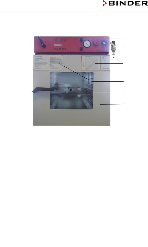
2.2Overview of the oven
(A)
(B)
(C)
(D)
(E)
(F)
Figure 4: VDL 53
(A)Area for electrical equipment swept with compressed air, and control panel
(B)Compressed air connection
(C)Information panel “Temperature setting”
(D)Information panel short description
(E)Spring-mounted safety glass window
(F)Unit door
VDL (E2.1) 04/2014 |
page 25/107 |

2.3VDL control panel
(7) |
(6) |
(5) |
(3) |
(4) |
(2) |
(2a) |
(1) |
AIR
GAS 


|
|
Figure 5: VDL 23 control panel |
|
|
|
|
|
|
(8) |
(7) |
(6) |
(5) |
(3) |
(4) |
(2) |
(2a) |
(1) |
VAC.OFF |
|
AIR |
|
|
|
|
|
|
VAC.ON |
GAS |
|
Figure 6: VDL 53/115 control panel
(1)Key switch (main power switch)
(2)Temperature safety device class 2
(2a) Red alarm lamp of the safety device class 2
(3)Manometer (pressure reading)
(4)Yellow pilot light: No heating release
(5)Aeration valve (ambient air)
(6)Fine dosing valve (inert gas)
(7)Program controller RD3
(8)Vacuum shut-off valve
VDL (E2.1) 04/2014 |
page 26/107 |
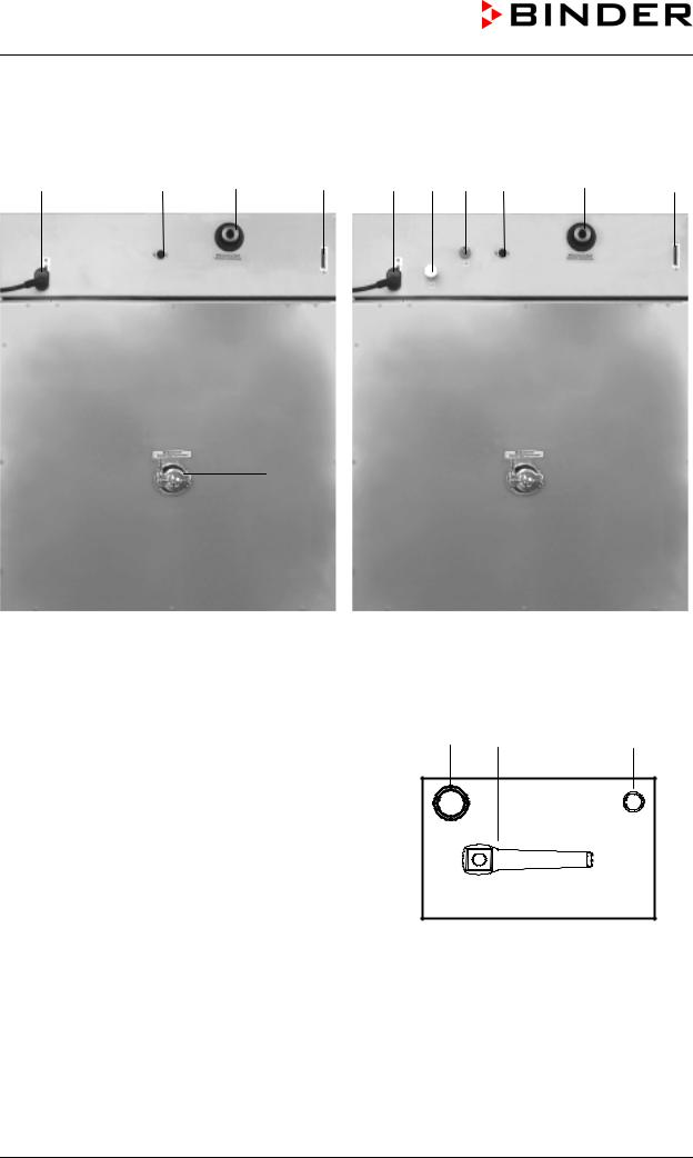
2.4Connections at the rear of the unit
(10) |
(14) |
(13) |
(9) |
(10) |
(11) |
(12) |
(14) |
(13) |
(9) |
(15) |
|
|
|
(15) |
|
|
|||
|
|
|
|
|
VDL 23 |
VDL 53 / VDL 115 |
|
Figure 7: Rear of VDL |
(8)Vacuum shut-off valve
(9)RS 422 serial interface for computer communication
(10)Power connection line
(11)Inert gas connection, adapter with hose olive
8 mm / 0.31 in
(12)Fresh air connection (tube 8x1 mm)
(13)Vacuum connection with small flange DN16
(14)DIN socket “Object-Pt100“ (option) to connect a Pt 100 sensor (with option “object temperature display”)
(15)Measuring connection with small flange DN16
(11) |
(8) |
(12) |
|
|
VAC.OFF |
GAS |
|
AIR |
|
|
VAC.ON |
Figure 8: Connections left side VDL 23
VDL (E2.1) 04/2014 |
page 27/107 |
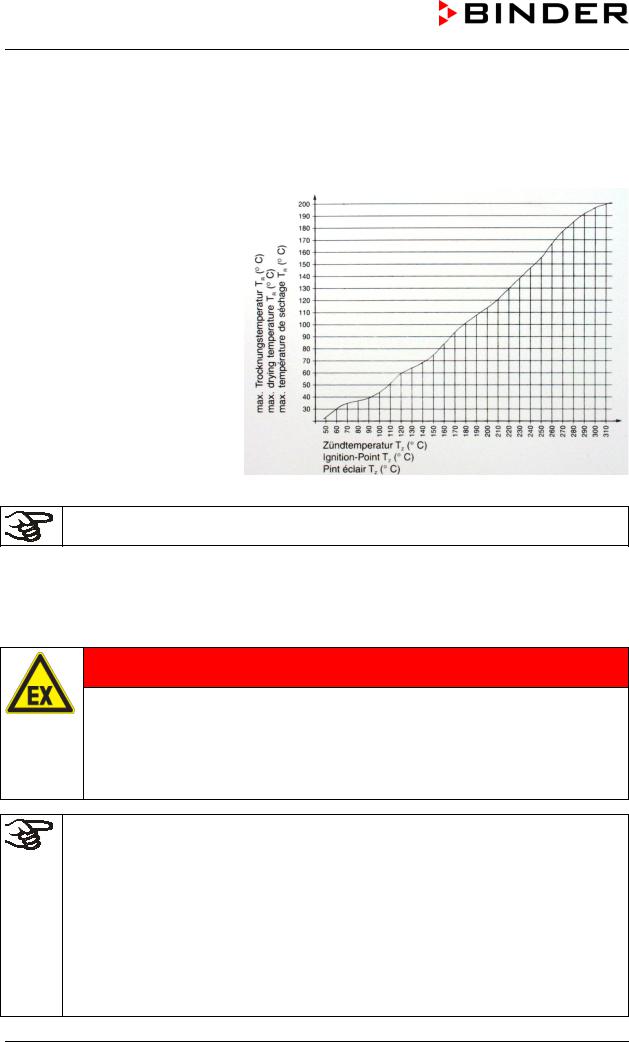
2.5“Temperature setting” information panel (ignition temperature vs. drying temperature)
Temperatureinstellung VDL
Adjustment of temperature VDL
This information panel is mounted to Ajustement de température VDL the door of the VDL vacuum drying
oven and shows the maximum permissible drying temperature depending on the ignition temperature of the solvent.
The reading graph reflects the fact that the inner chamber walls will become warmer than the expansion racks, especially during the heatingup phase, and will thereby exceed the set-point temperature.
Figure 9: Temperature setting information panel
You must observe the indicated safety margin between ignition temperature and drying temperature.
According to IEC 60079-14, you must introduce only substances with an ignition temperature which is higher than 135 °C / 275°F. This unit is NOT suitable to dry substances with an ignition temperature below 135 °C / 275°F.
If the ignition temperature of a solvent contained in the drying material is exceeded during the drying process, there is an immediate risk of fire and explosion.
 DANGER
Exceeding the ignition temperature of a solvent.
Risk of fire and explosion.
Danger of death.
The ignition temperature of a contained solvent must NEVER be reached. For safety reasons, always ensure that there is a safety margin.
Required measures:
• Determine the maximum drying temperature in relation to the ignition temperature of the solvent in accordance with the “Temperature setting” information panel (chap. 2.5). Do NOT exceed this temperature when presetting the set-point temperature at the temperature controller RD3.
•Before starting the drying process, set the temperature safety device to the allowed maximum drying temperature according to the information panel “temperature setting” chap. 2.5), so that even in the event of error or incorrect increase of the temperature set-point on the RD3 controller the maximum permissible drying temperature is not exceeded. It is NOT sufficient to directly adjust the maximum temperature of the temperature safety device to the maximum temperature of the solvent’s temperature class.
•(continued)
VDL (E2.1) 04/2014 |
page 28/107 |

Required measures (continuation):
• During the drying process, use only those solvents for which the temperature setting has been performed.
•In the case of solvent mixtures, use the ignition temperature of the material with the lowest ignition temperature. For the ignition temperature, refer to the safety specifications of the solvent.
•Let the oven cool down to ambient temperature before you start a new drying process with a modified ignition temperature.
2.6Overview of the zone classification of the ovens
Figure 10: Zone classification VDL 23
VDL (E2.1) 04/2014 |
page 29/107 |

Figure 11: Zone classification VDL 53 and 115
VDL (E2.1) 04/2014 |
page 30/107 |
Loading...