


CB (E2) Service Manual
state: 01/2002 |
created: 03/2002 / Jochen Tussinger |
CB (E2) Service Manual
08:43:55 |
20.11.01 |
|
|
W |
X |
|
37.0 |
36.8 |
°C |
TEMP |
|
|
EXIT |
CO2 |
5.0 |
4.9 |
% |
O2 |
25.0 |
25.2 |
% |
CONFIG |
W |
RESET MENUE |
VIEW-> |
Version of the described Chamber :
Standard equipped CB CO2 Incubator E2 with
FPI Sensor System and
MB1 Controller
SERIAL-NO. 01-27954 à
Order-No. 9040-0012 / CB 150
Order-No. 9040-0013 / CB 210

|
|
|
CB (E2) Service Manual |
|
|
|
|
|
|
|
|
|
|
|
|
|
state: 01/2002 |
|
created: 03/2002/ Jochen Tussinger |
|
Contents |
|
|
||||
1 |
Modification levels ................................................................................................................... |
|
3 |
|||
2 |
Unit overview .......................................................................................................................... |
|
4 |
|||
|
2.1 |
The Controller MB1........................................................................................................... |
|
5 |
||
|
2.2 |
Short description of the MB1 Controller .............................................................................. |
|
6 |
||
3 |
Function ............................................................................................................................... |
|
12 |
|||
|
3.1 |
The CO2-measuring principle........................................................................................... |
|
12 |
||
|
3.2 |
Function of the Heating System ....................................................................................... |
|
12 |
||
|
3.3 |
Flow-Chart of the heating function (basis CB 150 wiring diagram)...................................... |
13 |
|||
|
3.4 |
Controller MB1 PIN description (Input / Output) |
................................................................ |
14 |
||
|
3.5 |
Function of the CO2 System ............................................................................................ |
|
15 |
||
|
3.6 |
Flow Chart of the CO2 System (basis CB wiring ..................................................diagram) |
15 |
|||
|
3.7 |
Function of the Permadry® system .................................................................................. |
|
16 |
||
|
3.8 |
Flow Chart of the Permadry® system (basis CB ........................................wiring diagram) |
17 |
|||
|
3.9 |
Description of the Function of the Fan Control .................................................................. |
|
17 |
||
|
3.10 |
|
Sterilization Mode ........................................................................................................ |
|
18 |
|
|
3.11 |
|
Hot - air sterilization ....................................................................................................... |
|
18 |
|
|
3.12 |
|
Hot - air sterilization with inner chamber contaminated ..........with highly infective material |
20 |
||
4 |
Trouble Shooting................................................................................................................... |
|
22 |
|||
5 Most common service work .................................................................................................... |
|
25 |
||||
|
5.1 |
Changeing of the fan....................................................................................................... |
|
26 |
||
|
5.2 |
Take out of the electronic component board ..................................................................... |
|
28 |
||
|
5.3 |
Opening of the rear service lid to achieve the area ....................................of the air jacket |
29 |
|||
|
5.4 |
Setting of the door heating............................................................................................... |
|
31 |
||
|
5.5 |
CO2-Reference Measurement .......................................................................................... |
|
32 |
||
|
5.5.1 |
Measuring of CO 2 indirectly via the pH of the ..........................................cell medium |
33 |
|||
|
5.5.2 |
Measuring of CO 2 directly via chemical indicator ...............................................tubes |
34 |
|||
|
5.5.3 |
Measuring of CO 2 directly via a electronic measuring .......................................device |
35 |
|||
6 |
Calibration ............................................................................................................................ |
|
36 |
|||
|
6.1 |
Definition of calibration .................................................................................................... |
|
36 |
||
|
6.2 |
References for calibration................................................................................................ |
|
36 |
||
|
6.3 |
Tolerance of the adjustment ............................................................................................ |
|
36 |
||
Calibration instructions for CO2 incubator CB with screen controller MB1 ........................................ |
37 |
|||||
Temperature / CO2 / O2 controller ................................................................................................ |
|
37 |
||||
|
Temperature calibration ............................................................................................................ |
|
37 |
|||
|
Calibration (alignment) of the temperature controller ................................................................... |
|
38 |
|||
|
Reading out of the actual values: ............................................................................................... |
|
39 |
|||
|
Entries: |
.................................................................................................................................... |
|
|
39 |
|
|
Result Calibration .........................................................(alignment) of the temperature controller |
39 |
||||
|
CO2 calibration ........................................................................................................(alignment) |
|
40 |
|||
|
O2 calibration ..........................................................................................................(alignment) |
|
41 |
|||
7 |
Maintenance ......................................................................................................................... |
|
48 |
|||
8 Explosion Drawings of the CB /E2.......................................................................................... |
|
51 |
||||
|
8.1 |
CB .....................................................................................................Component Board |
|
51 |
||
|
8.2 |
CB .........................................................................Kettle / Sensors / Heaters / Permadry |
|
52 |
||
|
8.3 |
CB ........................................................................................Door / Sealing / Inner parts |
|
53 |
||
2

CB (E2) Service Manual
state: 01/2002 |
created: 03/2002/ Jochen Tussinger |
1 Modification levels
The CB CO2 Incubator E2 is a further development of CB CO2 Incubator E1. Especially the Display controller MB1 inside the red triangle is conspicuous.
The whole electronic is placed inside the lower part of the CB CO2 Incubator (Front Access Maintenance). Theres no I-box as at the CB CO2 Incubator E1 at the top of the chamber.
08:43:55 |
20.11.01 |
|
|
|
W |
X |
|
TEMP |
37.0 |
36.8 |
EXIT |
|
°C |
||
CO2 |
5.0 |
4.9 |
% |
|
|
||
O2 |
25.0 |
25.2 |
% |
|
|||
CONFIG |
W |
RESET MENUE |
VIEW-> |
Display Controller MB1
Display controller MB1
Machine Room with all electronic parts
3
CB (E2) Service Manual
state: 01/2002 |
created: 03/2002/ Jochen Tussinger |
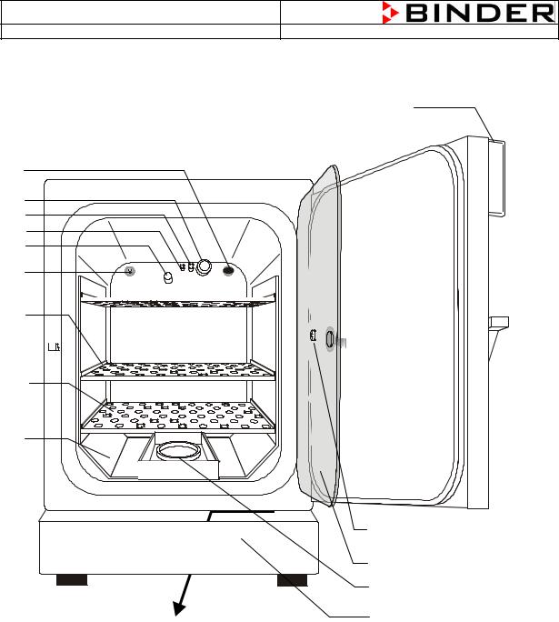
2 Unit overview
(A)
(B)
(C)
(D)
(E)
(F)
(G)
(H)
(I)
(J)
FRONT
Machine 
 room with all electronic parts (N)
(M)
(L)
(K)
A)Display controller MB1 for temperature and CO2 as well as O2 (option)
B)Connection socket for low tension supply (option)
C)CO2 sensor
D)Gas mixing head
E)PT 100 temperature probe
F)O2 sensor (option)
G)Internal socket 230V (max. 3 A) (option)
H)Shelf holder bar
I)Shelves
J)Shelf holder
K)Lower housing cover
L)Permadry® water basins
M)Inner glass door
N)Measuring access port
4
CB (E2) Service Manual
state: 01/2002 |
created: 03/2002/ Jochen Tussinger |
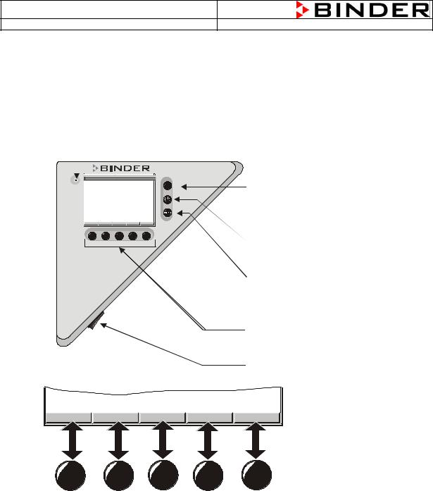
2.1The Controller MB1
Display Controller MB1
Operating Light |
|
|||
08:43:55 |
W |
X |
EXIT-Button |
|
20.11.01 |
36.8 °C |
|
||
TEMP |
37.0 |
(to leave a |
||
|
|
EXIT |
||
C2O |
5.0 |
4.9 % |
||
Menue) |
||||
O2 |
25.0 |
25.2 % |
||
CONFIG |
W |
RESET MENUE VIEW-> |
ON / OFF Button |
|
|
|
|
||
|
|
|
(Stand-by) |
|
|
|
|
ENTER-Button |
|
|
|
|
((to confirm a |
|
|
|
|
selection) |
|
|
|
|
Navigation buttons |
|
|
|
|
(corresponding function |
|
|
|
|
will be assigned) |
|
|
|
|
Mainswitch |
|
CONFIG |
W |
RESET |
MENUE |
VIEW-> |
For the controller MB1, it is possible to show all setpoints and actual values at the same time. It is also possible to display the actual values portrary.
5

CB (E2) Service Manual
state: 01/2002 |
created: 03/2002/ Jochen Tussinger |
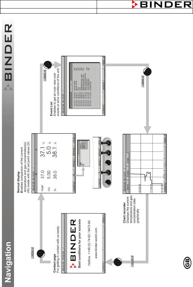
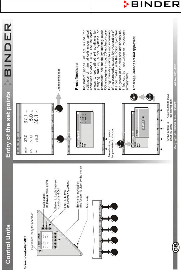
2.2Short description of the MB1 Controller
6
CB (E2) Service Manual
state: 01/2002 |
created: 03/2002/ Jochen Tussinger |
7
CB (E2) Service Manual
state: 01/2002 |
created: 03/2002/ Jochen Tussinger |
8
CB (E2) Service Manual
state: 01/2002 |
created: 03/2002/ Jochen Tussinger |
9

CB (E2) Service Manual
state: 01/2002 |
created: 03/2002/ Jochen Tussinger |
10
CB (E2) Service Manual
state: 01/2002 |
created: 03/2002/ Jochen Tussinger |
11

CB (E2) Service Manual
state: 01/2002 |
created: 03/2002/ Jochen Tussinger |
3 Function
Incubators series CB are suited for cultivation of mammal cells under typical conditions of about 37°C. The incubator allows the set defined pH conditions by justifying NaHCO3 buffer systems of commercial cell media by keeping exact CO2-atmosphere inside. CB incubators care for high humidity inside to avoid increasing of the osmolarity caused by evaporation of the cell media. To reach this, the different functions heating, sterilization and CO2 injection have to work as a perfect team. This know-how is as Firmware inside the controller type MB1.
3.1The CO2-measuring principle
The CO2-measuring procedure of the incubator series CB is characterized by fast reaction times, as well as the highest accuracy and selectivity. The accuracy of the CO2 measuring system bases on a single-beam infrared measuring cell, which measures in differential mode, with permanently alternating transmission characteristic of its semi-conductor filter. Due to this highly developed singlebeam principle with Fabry-Perot interferometer (FPI), disturbance variables and aging phenomena in the measuring system are almost completely eliminated, so that this measuring system, in contrast to other measuring procedures, remains practically drift-free between calibrations and is absolutely selective for CO2.
The CO2–measuring cell contains a measuring section inside in which the absorption of infrared light depends on the number of CO2 -molecules in the beam path. This number of CO2 –molecules changes with the ambient pressure in relation to a constant volume. The distances between the molecules are consequently pressure-dependent. The collision frequency of the IR-beam with CO2-molecules increases therefore by increasing pressure.
For this reason, the ambient pressure must be compensated in order to correct the display reading of the CO2 -concentration in VOL.-%. This is achieved by entering the altitude of the site above the sea which is described in this manual.
3.2Function of the Heating System
The temperature measurement is realized by a PT100 temperature probe which changes his resistance at different temperatures. For example: 37°C = 114,380 Ω (see following chart).
The CB is equipped with a double PT100, one part is for the measurement inside the chamber, the other part is connected to the safety device class 3.1.
The measured value is evaluated in the controller MB1. The controller MB1 compares the set-value and the now measured value and decides to give a signal-current to the solid state relay –4K3 to activate the heating.
12
CB (E2) Service Manual
state: 01/2002 |
created: 03/2002/ Jochen Tussinger |
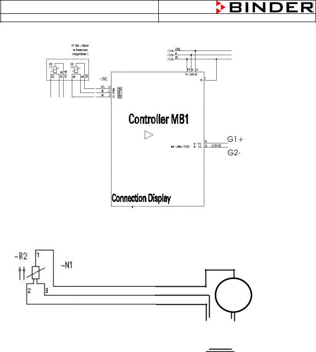
3.3Flow-Chart of the heating function (basis CB 150 wiring diagram)
The Pt100 temperature probe is equipped with 3 cables, two red and one white cable.
The white cable is connected to pin 1 at E1 – Pt100, the two red cables at pin’s 2 and 3 at E1 – Pt100. To measure the resistance disconnect all three cables from the controller an measure between the white cable and one of the red cables, do not measure between both red cables.
Ω
Measuring of the Pt100 resistance between the white cable PIN 1 and one of the two red cables PIN 2 or 3
13
|
|
|
|
CB (E2) Service Manual |
|
|
|
|
|
|
|
|
|
|
|
||||
|
|
|
|
|
|
|
|
|
|
|
|
|
|
|
|
|
|
|
|
|
|
|
|
|
state: 01/2002 |
|
|
|
|
created: 03/2002/ Jochen Tussinger |
|||||||||
|
Pt100 temperature probe (Temperature in °C / Resistance in Ω) |
|
|
|
|
|
|
|
|||||||||||
|
|
|
|
|
|
|
|
|
|
|
|
|
|
|
|
|
|
|
|
|
T (°C) |
0 |
1 |
2 |
|
3 |
4 |
5 |
6 |
|
|
7 |
8 |
9 |
10 |
|
|||
|
|
|
|
||||||||||||||||
|
-10 |
|
|
96,086 |
96,478 |
96,870 |
|
97,262 |
97,653 |
98,045 |
98,436 |
|
98,827 |
99,218 |
99,609 |
100,000 |
|
||
|
0 |
|
|
100,000 |
100,391 |
100,781 |
|
101,172 |
101,562 |
101,953 |
102,343 |
|
102,733 |
103,123 |
103,513 |
103,902 |
|
||
|
10 |
|
|
103,902 |
104,292 |
104,681 |
|
105,071 |
105,460 |
105,849 |
106,238 |
|
106,627 |
107,016 |
107,404 |
107,793 |
|
||
|
20 |
|
|
107,793 |
108,181 |
108,570 |
|
108,958 |
109,346 |
109,734 |
110,122 |
|
110,509 |
110,897 |
111,284 |
111,672 |
|
||
|
30 |
|
|
111,672 |
112,059 |
112,446 |
|
112,833 |
113,220 |
113,607 |
113,994 |
|
114,380 |
114,767 |
115,153 |
115,539 |
|
||
|
|
|
|
|
|
||||||||||||||
|
|
|
|
|
|
|
|
|
|
|
|
|
|
|
|
|
|
|
|
|
40 |
|
|
115,539 |
115,925 |
116,311 |
|
116,697 |
117,083 |
117,469 |
117,854 |
118,240 |
118,625 |
119,010 |
119,395 |
|
|||
|
50 |
|
|
119,395 |
119,780 |
120,165 |
|
120,550 |
120,934 |
121,319 |
121,703 |
122,087 |
122,471 |
122,855 |
123,239 |
|
|||
|
60 |
|
|
123,239 |
123,623 |
124,007 |
|
124,390 |
124,774 |
125,157 |
125,540 |
125,923 |
126,306 |
126,689 |
127,072 |
|
|||
|
70 |
|
|
127,072 |
127,454 |
127,837 |
|
128,219 |
128,602 |
128,984 |
129,366 |
129,748 |
130,130 |
130,511 |
130,893 |
|
|||
|
80 |
|
|
130,893 |
131,274 |
131,656 |
|
132,037 |
132,418 |
132,799 |
133,180 |
133,561 |
133,941 |
134,322 |
134,702 |
|
|||
|
90 |
|
|
134,702 |
135,083 |
135,463 |
|
135,843 |
136,223 |
136,603 |
136,982 |
137,362 |
137,741 |
138,121 |
138,500 |
|
|||
|
100 |
|
|
138,500 |
138,879 |
139,258 |
|
139,637 |
140,016 |
140,395 |
140,773 |
141,152 |
141,530 |
141,908 |
142,286 |
|
|||
|
|
|
|
|
|
|
|
|
|
|
|
|
|
|
|
|
|
|
|
For Example: Your resistance measurement system shows you 114,380 Ω this corresponds to 37°C.
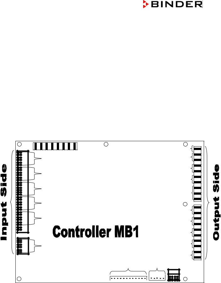
3.4 Controller MB1 PIN description (Input / Output)
BE1 BE2 BE3 BE4
|
Ground TE |
|
E1 – Pt100 |
Output Phase-controll |
|
3A / 115-230V AC |
||
|
Heater air-duct |
|
E2 – Pt100 |
BA2 – 1A / 115-230V AC |
|
Door Heater |
||
|
||
|
BA3 – 1A / 115-230V AC |
|
E3 – Pt100 |
Collection Alarm |
|
|
||
|
BA1 – 3A / 115-230V AC |
|
E4 – 4 - 20mA |
|
|
|
Heater Kettle |
|
|
BA4 – 60mA / 5V DC |
|
E2 – Pt100 |
CO2 Solenoid valve |
|
|
BA5 – 60mA / 5V DC |
|
|
Safety device Cl 3.1 |
|
|
BA6 – 60mA / 5V DC |
|
|
Fan Cold water bassin |
|
E – Safety device class 3.1 |
0(2)-10V / 0(4)-20mA |
|
|
Volatge output |
|
|
45mA / 24VDC |
|
Display connection |
RS422 |
14
CB (E2) Service Manual
state: 01/2002 |
created: 03/2002/ Jochen Tussinger |
3.5Function of the CO2 System
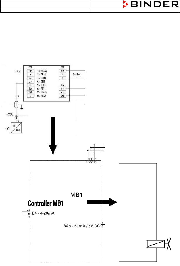
The CO2 System measures the CO2 concentration inside the chamber. This information is supplied by the FPI Sensor Head. The Controller MB1 compares the engaged value with the now measured value and decides to open the solenoid valve of the CO2 gas inlet.
3.6Flow Chart of the CO2 System (basis CB wiring diagram)
FPI-Sensor à FPI Sensor Board à Controller MB1 à Solenoid Valve à Gas Injection Nozzle
|
|
|
|
|
|
|
|
1 |
– white |
|
|
|
|
|
|
|
|
|
|
||
|
|
|
|
|
|
|
|
2 |
– grey |
To A1+ / A2- |
|
|
|
|
|
|
|
|
3 |
– green |
|
|
|
|
|
|
4 |
– yellow |
|
|||
|
|
|
|
|
5 |
– blue |
|
|||
|
|
|
|
|
6 |
– red |
To Power supply at the Transformer |
|||
|
|
|
|
|
|
|
|
7 |
– brown |
|
|
|
|
|
|
|
|||||
|
|
|
|
|
8 |
- pink |
|
|||
|
|
|
|
|
|
|
|
|
|
|
|
|
|
|
|
|
|
|
|
|
|
|
|
|
|
|
|
|
|
|
|
|
|
|
|
|
|
|
|
|
|
|
|
|
|
|
|
|
|
|
|
|
|
|
|
|
|
|
|
|
|
|
|
|
|
|
|
|
|
|
|
|
|
|
|
|
H1+
Solenoid Valve CO2
1
-5Y1
2
H2-
15

CB (E2) Service Manual
state: 01/2002 |
created: 03/2002/ Jochen Tussinger |
3.7Function of the Permadry® system
Isotonic osmotic pressure ratios, essential for the growth of cells, are basically maintained in CO2 incubators by a maximum humidity content in the inner chamber. During this process care must be taken to ensure the best possible protection against contamination.
The patented Permadry® system guarantees a humidity performance of up to 98% relative humidity with completely dry inner walls. The principle hereof is totally easy. The double basin system consists of a large-surface warm water basin an a cold water basin as defined condensation point. The temperatures of both basins are in that way controlled that the humidification and the dehumidification are permanently balanced. The Permadry® system works completely free of disturbances or maintenance. The handling of the Permadry® system is the easiest thing and as safe as a coffee cup. The basin is easily removable and can be refilled in or at the unit at any time.
Cold air, produced by the Permadry® -fan, streams through the air-channel and cools the round cold water basin. The condensation point is fixed by this.
The Permadry® water basin must be placed correctly. There is a description „FRONT“ impressed.
Lettering „FRONT“
16
 Loading...