


 Loading...
Operating Manual
APT.line™ MK (E2.1)
Alternating climate chamber with program control
Model |
Art. No. |
MK 53 (E2.1) |
9020-0006, 9120-0006 |
BINDER GmbH
Address |
Post office box 102 |
|
|
D-78502 Tuttlingen |
|
Tel. |
+49 |
7462 2005 0 |
Fax |
+49 |
7462 2005 100 |
Internet |
http://www.binder-world.com |
|
info@binder-world.com |
||
Service Hotline |
+49 |
7462 2005 555 |
Service Fax |
+49 |
7462 2005 93 555 |
Service E-Mail |
service@binder-world.com |
|
Service Hotline USA |
+1 866 885 9794 or +1 631 224 4340 x3 |
|
Service Hotline Asia Pacific |
+852 390 705 04 or +852 390 705 03 |
|
Service Hotline Russia and CIS |
+7 495 988 15 16 |
|
Issue 10/2014 |
Art. Nr. 7001-0028 |
|
|

EC – Declaration of Conformity
EG – KONFORMITÄTSERKLÄRUNG
EC - DECLARATION OF CONFORMITY
CE - DECLARATION DE CONFORMITE
Anbieter / Supplier / Fournisseur: |
BINDER GmbH |
Anschrift / Address / Adresse: |
Im Mittleren Ösch 5, D-78532 Tuttlingen |
Produkt / Product / Produit: |
Umweltsimulations-Schrank für klassische Temperaturprofile |
|
mit Programmregelung |
|
Environmental simulation chamber for traditional temperature |
|
profiles with program control |
|
Chambre d'essais climatiques pour profils thermiques clas- |
|
siques à régulation programmable |
Typenbezeichnung / Type / Type: |
MK 53 |
Die oben beschriebenen Produkte sind konform mit folgenden EG-Richtlinien: The products described above are in conformity with the following EC guidelines: Les produits décrits ci-dessus sont conformes aux directives CE suivantes:
Niederspannungsrichtlinie 2006/95/EG
Low voltage directive 2006/95/EC
Directive basse tension 2006/95/CE
EMV-Richtlinie 2004/108/EG
EMC Directive 2004/108/EC
Directive CEM 2004/108/CE
Richtlinie 2006/95/EG des Europäischen Parlaments und des Rates vom 12. Dezember 2006 zur Angleichung der Rechtsvorschriften der Mitgliedstaaten betreffend elektrische Betriebsmittel zur Verwendung innerhalb bestimmter Spannungsgrenzen
Council Directive 2006/95/EC of 12 December 2006 on the harmonization of the laws of Member States relating to electrical equipment designed for use within certain voltage limits
Directive 2006/95/CE du Parlement Européen et du Conseil du 12 décembre 2006 concernant le rapprochement des législations des États membres relatives au matériel électrique destiné à être employé dans certaines limites de tension
Richtlinie 2004/108/EG des Europäischen Parlaments und des Rates vom 15. Dezember 2004 zur Angleichung der Rechtsvorschriften der Mitgliedstaaten über die elektromagnetische Verträglichkeit und zur Aufhebung der Richtlinie 89/336/EWG.
Directive 2004/108/EC of the European Parliament and of the Council of 15 December 2004 on the approximation of the laws of the Member States relating to electromagnetic compatibility and repealing Directive 98/336/EEC.
Directive 2004/108/CE du Parlement Européen et du Conseil du 15 décembre 2004 relative au rapprochement des législations des États membres concernant la compatibilité électromagnétique et abrogeant le directive 98/336/CEE.
Die oben beschriebenen Produkte tragen entsprechend die Kennzeichnung CE. The products described above, corresponding to this, bear the CE-mark.
Les produits décrits ci-dessus, en correspondance, portent l’indication CE.
1 / 3
MK (E2.1) 10/2014 |
page 2/73 |

Die oben beschriebenen Produkte sind konform mit folgenden harmonisierten Normen: The products described above are in conformity with the following harmonized standards: Les produits décrits ci-dessus sont conformes aux normes harmonisées suivantes:
Sicherheit / safety / sécurité: |
|
EN 61010-1:2010 |
Sicherheitsbestimmungen für elektrische Mess-, Steuer-, Regelund |
|
Laborgeräte – Teil 1: Allgemeine Anforderungen (DIN EN 61010-1:2011, |
|
VDE 411-1:2011) |
|
Safety requirements for electrical equipment for measurement, control, |
|
and laboratory use – Part 1: General requirements (IEC 61010-1:2010, |
|
BS EN 61010-1:2010) |
|
Règles de sécurité pour appareils électriques de mesurage, de régula- |
|
tion et de laboratoire – Partie 1: Prescriptions générales (CEI 61010- |
|
1:2010, NF EN 61010:2011) |
EN 61010-2-010:2003 |
Sicherheitsbestimmungen für elektrische Meß-, Steuer-, Regelund |
|
Laborgeräte – Teil 2-010: Besondere Anforderungen an Laborgeräte für |
|
das Erhitzen von Stoffen (DIN EN 61010-2-010:2004) |
|
Safety requirements for electrical equipment for measurement, control, |
|
and laboratory use – Part 2-010: Particular requirements for laboratory |
|
equipment for the heating of materials (IEC 61010-2-10:2005, BS EN |
|
61010-2-10:2003) |
|
Règles de sécurité pour appareils électriques de mesurage, de régula- |
|
tion et de laboratoire – Partie 2-010 : Prescriptions particulières pour |
|
appareils de laboratoire utilisés pour l’échauffement des matières (CEI |
|
61010-2-10:2003, NF EN 61010-2-10:2005) |
EMV / EMC / CEM: |
|
EN 61326-1:2006 |
Elektrische Mess-, Steuer-, Regelund Laborgeräte - EMV- |
+ Corr. 1:2008 + Corr. 2:2010 Anforderungen - Teil 1: Allgemeine Anforderungen (DIN EN 61326- |
|
|
1:2006 + Berichtigung 1:2008 + Berichtigung 2:2011) |
|
Electrical equipment for measurement, control and laboratory use - |
|
EMC requirements - Part 1: General requirements (IEC 61326-1:2005 + |
|
Corr. 1:2008 + Corr. 2:2010, BS EN 61326-1:2006+ A1:2008) |
|
Matériel électrique de mesure, de commande et de laboratoire - Exi- |
|
gences relatives à la CEM - Partie 1: Exigences générales (CEI 61326- |
|
1:2005 + AC1:2008, NF EN 61326-1:2006 mod.) |
EN 61326-2-2:2006 |
Elektrische Mess-, Steuer-, Regelund Laborgeräte – EMV- |
|
Anforderungen. Teil 2-2: Besondere Anforderungen - Prüfanordnung, |
|
Betriebsbedingungen und Leistungsmerkmale für ortsveränderliche |
|
Prüf-, Messund Überwachungsgeräte in Niederspannungs- |
|
Stromversorgungsnetzen. (DIN EN 61326-2-2:2006) |
|
Electrical equipment for measurement, control and laboratory use – |
|
EMC requirements. Part 2-2: Particular requirements - Test configura- |
|
tions, operational conditions and performance criteria for portable test, |
|
measuring and monitoring equipment used in low-voltage distribution |
|
systems. (IEC 61326-2-2:2005, BS EN 61326-2-2:2006) |
|
Matériel électrique de mesure, de commande et de laboratoire – Exi- |
|
gences relatives à la CEM. Partie 2-2: Exigences particulières - Configu- |
|
rations d’essai, conditions de fonctionnement et critères d’aptitude à la |
|
fonction des matériels portatifs d’essai, de mesure et de surveillance |
|
utilisés dans des systèmes de distribution basse tension. (CEI 61326-2- |
|
2:2005 + AC1:2007, NF EN 61326-2-2:2006) |
|
2 / 3 |
|
|
MK (E2.1) 10/2014 |
page 3/73 |
D-78532 Tuttlingen, 16.01.2013
BINDER GmbH
P. M. Binder |
B. Hofmann |
Geschäftsführender Gesellschafter |
Leiter F & E |
Managing Director |
Director R & D |
Directeur général |
Chef de service R&D |
3 / 3
MK (E2.1) 10/2014 |
page 4/73 |

Product registration
MK (E2.1) 10/2014 |
page 5/73 |

CONTENTS
EC – Declaration of Conformity..................................................................................................................... |
2 |
||
Product registration ....................................................................................................................................... |
5 |
||
1. |
SAFETY.................................................................................................................. |
8 |
|
1.1 |
Legal considerations ........................................................................................................................... |
8 |
|
1.2 |
Structure of the safety instructions...................................................................................................... |
8 |
|
|
1.2.1 |
Signal word panel ...................................................................................................................... |
8 |
|
1.2.2 |
Safety alert symbol .................................................................................................................... |
9 |
|
1.2.3 |
Pictograms................................................................................................................................. |
9 |
|
1.2.4 |
Word message panel structure ............................................................................................... |
10 |
1.3 |
Localization / position of safety labels on the unit ............................................................................. |
10 |
|
1.4 |
Type plate.......................................................................................................................................... |
11 |
|
1.5 |
General safety instructions on installing and operating the alternating climate chamber MK ........... |
12 |
|
1.6 |
Intended use...................................................................................................................................... |
14 |
|
2. |
UNIT DESCRIPTION ............................................................................................ |
15 |
|
2.1 |
Unit overview..................................................................................................................................... |
16 |
|
2.2 |
Instrument box MK ............................................................................................................................ |
16 |
|
2.3 |
Lateral control panel MK ................................................................................................................... |
17 |
|
3.COMPLETENESS OF DELIVERY, TRANSPORTATION, STORAGE, AND
|
INSTALLATION.................................................................................................... |
18 |
3.1 |
Unpacking, and checking equipment and completeness of delivery................................................. |
18 |
3.2 |
Guidelines for safe lifting and transportation..................................................................................... |
19 |
3.3 |
Storage.............................................................................................................................................. |
19 |
3.4 |
Location of installation and ambient conditions................................................................................. |
19 |
4. |
INSTALLATION AND CONNECTIONS................................................................ |
21 |
4.1 |
Electrical connection ......................................................................................................................... |
21 |
5. |
START UP ............................................................................................................ |
22 |
5.1 |
Function overview of display program controller MB1....................................................................... |
22 |
5.2 |
Operating modes............................................................................................................................... |
23 |
5.3 |
Behavior after power failure .............................................................................................................. |
23 |
5.4 |
Performance when opening the door ................................................................................................ |
23 |
5.5 |
Turning on the unit ............................................................................................................................ |
23 |
6. |
CONTROLLER MB1 SETTINGS.......................................................................... |
25 |
6.1 |
Selection of the menu language........................................................................................................ |
25 |
6.2 |
Overview of program controller MB1 displays................................................................................... |
26 |
6.3 |
Menu settings in the “User-settings” menu ....................................................................................... |
27 |
6.4 |
Menu settings in the “User Level” menu ........................................................................................... |
28 |
7.GRAPHICAL REPRESENTATION OF THE HISTORICAL MEASUREMENT
|
(CHART RECORDER FUNCTION) ..................................................................... |
29 |
7.1 |
Setting the storage rate ..................................................................................................................... |
31 |
8. |
MANUAL MODE................................................................................................... |
32 |
8.1 |
Set-point entry ................................................................................................................................... |
32 |
8.2 |
Performance after power failure in Manual Mode ............................................................................. |
33 |
9. |
PROGRAM OPERATION ..................................................................................... |
33 |
9.1 |
Overview menu-based program entry............................................................................................... |
34 |
9.2 |
Selecting between set-point ramp and set-point step ....................................................................... |
36 |
9.3 |
Program entry as set-point ramp or as set-point step....................................................................... |
36 |
MK (E2.1) 10/2014 |
page 6/73 |
|

9.4 |
Information on programming different temperature transitions......................................................... |
|
39 |
|
9.5 |
Repetition of a section or several sections within a program ............................................................ |
|
40 |
|
9.6 |
Performance after power failure in Program Mode ........................................................................... |
|
40 |
|
9.7 |
Starting a previously entered program .............................................................................................. |
|
41 |
|
9.8 |
Deleting a program............................................................................................................................ |
|
41 |
|
9.9 |
Temperature profile and operation lines template............................................................................. |
|
42 |
|
9.10 |
Program table template..................................................................................................................... |
|
43 |
|
10. |
BEDEW PROTECTION FACILITY (OPERATION LINE 1) .................................. |
|
44 |
|
11. |
TEMPERATURE SAFETY DEVICES ................................................................... |
|
45 |
|
11.1 |
Over-temperature protective device (class 1) ................................................................................... |
|
45 |
|
11.2 |
Safety controller (over-temperature safety device class 2) ............................................................... |
|
45 |
|
11.3 |
Over/under temperature safety device class 2 (option) .................................................................... |
|
47 |
|
12. |
NOTIFICATION AND ALARM FUNCTIONS ........................................................ |
|
48 |
|
12.1 |
Notification and alarm system overview (auto diagnosis system)..................................................... |
|
48 |
|
12.2 |
Resetting the notifications or alarm messages ................................................................................. |
|
48 |
|
13. |
NOTES ON REFRIGERATING OPERATION ...................................................... |
|
49 |
|
14. |
OPTIONS.............................................................................................................. |
|
50 |
|
14.1 |
Communication software APT-COM™ 3 DataControlSystem (option)............................................. |
|
50 |
|
14.2 |
Analog output for temperature (option) ............................................................................................. |
|
50 |
|
14.3 |
Keyboard locking (option).................................................................................................................. |
|
50 |
|
14.4 |
Data logger kit ................................................................................................................................... |
|
51 |
|
14.5 |
Additional measuring channel for digital object temperature indicator with flexible temperature |
|
||
|
sensor Pt 100 (option) ....................................................................................................................... |
|
51 |
|
15. |
MAINTENANCE, CLEANING, AND SERVICE..................................................... |
|
52 |
|
15.1 |
Maintenance intervals, service .......................................................................................................... |
|
52 |
|
15.2 |
Cleaning and decontamination.......................................................................................................... |
|
53 |
|
15.2.1 |
Cleaning................................................................................................................................... |
|
53 |
|
15.2.2 |
Decontamination...................................................................................................................... |
|
54 |
|
15.3 |
Sending back the unit to the BINDER GmbH.................................................................................... |
|
55 |
|
16. |
DISPOSAL............................................................................................................ |
|
56 |
|
16.1 |
Disposal of the transport packing...................................................................................................... |
|
56 |
|
16.2 |
Decommissioning.............................................................................................................................. |
|
56 |
|
16.3 |
Disposal of the unit in the Federal Republic of Germany.................................................................. |
|
56 |
|
16.4 |
Disposal of the unit in the member states of the EC except for the Federal Republic of Germany |
..58 |
||
16.5 |
Disposal of the unit in non-member states of the EC........................................................................ |
|
59 |
|
17. |
TROUBLESHOOTING ......................................................................................... |
|
60 |
|
18. |
TECHNICAL DESCRIPTION................................................................................ |
|
62 |
|
18.1 |
Factory calibration and adjustment ................................................................................................... |
|
62 |
|
18.2 |
Over-current protection ..................................................................................................................... |
|
62 |
|
18.3 |
Definition of usable volume ............................................................................................................... |
|
62 |
|
18.4 |
Technical Data MK 53 (E2.1) ............................................................................................................ |
|
63 |
|
18.5 |
Equipment and options MK 53 .......................................................................................................... |
|
64 |
|
18.6 |
Accessories and spare parts MK 53 ................................................................................................. |
|
65 |
|
18.7 |
Heating-up and cooling-down graphs................................................................................................ |
|
66 |
|
18.8 |
Heat compensation ........................................................................................................................... |
|
66 |
|
18.9 |
Dimensions MK 53 ............................................................................................................................ |
|
67 |
|
19. |
CONTAMINATION CLEARANCE CERTIFICATE ................................................ |
|
68 |
|
19.1 |
For units located outside North America and Central America ......................................................... |
|
68 |
|
19.2 |
For units in North America and Central America............................................................................... |
|
71 |
|
|
|
|||
MK (E2.1) 10/2014 |
page 7/73 |
|||

Dear customer,
For the correct operation of the alternating climate chamber MK, it is important that you read this operating manual completely and carefully and observe all instructions as indicated. Failure to read, understand and follow the instructions may result in personal injury. It can also lead to damage to the unit and/or poor equipment performance.
1.Safety
This operating manual is part of the components of delivery. Always keep it handy for reference. The device should only be operated by laboratory personnel especially trained for this purpose and familiar with all precautionary measures required for working in a laboratory. Observe the national regulations on minimum age of laboratory personnel. To avoid injuries and damage observe the safety instructions of the operating manual.
 WARNING
Failure to observe the safety instructions.
Serious injuries and unit damage.
Observe the safety instructions in this operating manual
Carefully read the complete operating instructions of the alternating climate chamber MK.
1.1Legal considerations
This operating manual is for informational purposes only. It contains information for installing, start-up, operation and maintenance of the product. Note: the contents and the product described are subject to change without notice.
Understanding and observing the instructions in this operating manual are prerequisites for hazard-free use and safety during operation and maintenance. In no event shall BINDER be held liable for any damages, direct or incidental arising out of or related to the use of this manual.
This operating manual cannot cover all conceivable applications. If you would like additional information, or if special problems arise that are not sufficiently addressed in this manual, please ask your dealer or contact us directly by phone at the number located on page one of this manual
Furthermore, we emphasize that the contents of this operating manual are not part of an earlier or existing agreement, description, or legal relationship, nor do they modify such a relationship. All obligations on the part of BINDER derive from the respective purchase contract, which also contains the entire and exclusively valid statement of warranty administration. The statements in this manual neither augment nor restrict the contractual warranty provisions.
1.2Structure of the safety instructions
In this operating manual, the following safety definitions and symbols indicate dangerous situations following the harmonization of ISO 3864-2 and ANSI Z535.6.
1.2.1 Signal word panel
Depending on the probability of serious consequences, potential dangers are identified with a signal word, the corresponding safety color, and if appropriate, the safety alert symbol.
 DANGER
Indicates an imminently hazardous situation that, if not avoided, will result in death or serious (irreversible) injury.
MK (E2.1) 10/2014 |
page 8/73 |
 WARNING
Indicates a potentially hazardous situation which, if not avoided, could result in death or serious (irreversible) injury
 CAUTION
Indicates a potentially hazardous situation which, if not avoided, may result in moderate or minor (reversible) injury
CAUTION
Indicates a potentially hazardous situation which, if not avoided, may result in damage to the product and/or its functions or of a property in its proximity.
1.2.2 Safety alert symbol
Use of the safety alert symbol indicates risk of injury.
Observe all measures that are marked with the safety alert symbol in order to avoid death or injury.
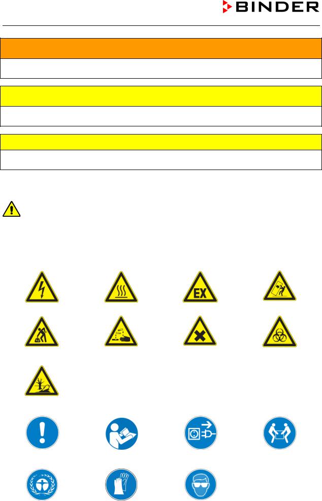
1.2.3 Pictograms
Warning signs |
|
|
|
Electrical hazard |
Hot surface |
Explosive atmosphere |
Stability hazard |
|
|
|
|
Lifting hazard |
Risk of corrosion and / |
Harmful substances |
Biohazard |
|
or chemical burns |
|
|
Pollution Hazard |
|
|
|
Mandatory action signs |
|
|
|
Mandatory regulation |
Read operating |
Disconnect the power |
Lift with several persons |
|
instructions |
plug |
|
Environment protection |
Wear protective gloves |
Wear safety goggles |
|
|
|
|
|
MK (E2.1) 10/2014 |
|
|
page 9/73 |

Prohibition signs
Do NOT touch |
Do NOT spray with |
Do NOT climb |
|
|
water |
|
|


 Information to be observed in order to ensure optimum function of the product.
1.2.4 Word message panel structure
Type / cause of hazard.
Possible consequences.
Instruction how to avoid the hazard: prohibition.
Instruction how to avoid the hazard: mandatory action.
Observe all other notes and information not necessarily emphasized in the same way, in order to avoid disruptions which could result in direct or indirect injury or property damage.
1.3Localization / position of safety labels on the unit
The following labels are located on the unit:
Pictograms (Warning signs)
Hot surface (on outer unit door)
Service label
Figure 1: Position of labels on the unit
Keep safety labels complete and legible.
Replace safety labels that are no longer legible. Contact BINDER service for these replacements.
MK (E2.1) 10/2014 |
page 10/73 |
1.4Type plate
The type plate sticks to the left side of the unit, bottom right-hand.
Nominal temperature |
180 |
°C |
2,60 kW |
|
356 |
°F |
230 V 1 N ~ |
Enclosure protection |
IP 20 |
11,3 A |
|
Temp. safety device |
DIN 12880 |
50 Hz |
|
Class |
2.0 |
|
|
Art. No. |
9020-0006 |
US PATS 4585923 / 5222612 / 5309981 |
|
Project No. |
|
|
5405194 / 5601143 / 5773287 / 6079403 |
Built |
2014 |
Alternating climate chamber |
|
D 78532 Tuttlingen / Germany
Tel. + 49 (0) 7462/ 2005-0
Internet: www.binder-world.com
Max. operating pressure 25 bar R 404 A – 0,85 KG
Contains fluorinated greenhouse gases covered by the Kyoto Protocol
.
MK 53 Serial No. 00-00000
E2.1 Made in Germany
Figure 2: Type plate (example of MK 53 regular unit)
Indications of the type plate (example) |
Information |
||
BINDER |
|
Manufacturer: BINDER GmbH |
|
MK 53 |
|
Model designation |
|
Alternating climate chamber |
Device name |
||
Serial No. |
00-00000 |
Serial no. of the unit |
|
Built |
2014 |
Year of construction |
|
Nominal temperature |
180 °C |
Nominal temperature |
|
356°F |
|||
|
|
||
Enclosure protection |
IP 20 |
IP type of protection acc. to EN 60529 |
|
Temp. safety device |
DIN 12880 |
Temperature safety device acc. to standard DIN 12880 |
|
Class |
2.0 |
Class of temperature safety device |
|
Art. No. |
9020-0006 |
Art. no. of the unit |
|
Project No. |
--- |
Optional: Special application acc. to project no. |
|
2,60 kW |
|
Nominal power |
|
230 V 1 N ~ |
|
Nominal voltage ± 10%, phase indication |
|
11,3 A |
|
Nominal current |
|
50 Hz |
|
Power frequency |
|
Max operating pressure 25 bar |
Max operating pressure in the refrigerating system |
||
R 404 A - 0,85 kg |
|
Refrigerant type and filling weight (0.85 kg / 1.87 lb) |
|
Contains fluorinated greenhouse gases covered by the Kyoto Protocol |
|||
Symbol on the type plate |
Information |
||||||||||
|
|
|
|
|
|
|
|
|
|
|
CE conformity marking |
|
|
|
|
|
|
|
|
|
|
|
|
|
|
|
|
|
|
|
|
|
|
|
Electrical and electronic equipment manufactured / placed |
|
|
|
|
|
|
|
|
|
|
|
on the market in the EC after 13 August 2005 and to be |
|
|
|
|
|
|
|
|
|
|
|
|
|
|
|
|
|
|
|
|
|
|
|
disposed of in separate collection according to directive |
|
|
|
|
|
|
|
|
|
|
|
2002/96/EC on waste electrical and electronic equipment |
|
|
|
|
|
|
|
|
|
|
|
(WEEE). |
|
|
|
|
|
|
|
|
|
|
|
|
|
|
|
|
|
|
|
|
|
|
|
|
MK (E2.1) 10/2014 |
page 11/73 |

Symbol on the type plate |
Information |
The equipment is certified in the GOST R certification
system of GOSTSTANDARD Russia.
or
The equipment is certified according to Customs Union
Technical Regulation (CU TR) for Russia, Belarus and
Kazakhstan
1.5General safety instructions on installing and operating the alternating climate chamber MK
With regard to operating the alternating climate chamber MK and to the installation location, please observe the guideline BGI/GUV-I 850-0 on safe working in laboratories (formerly BGR/GUV-R 120 or ZH 1/119 laboratory guidelines issued by the employers’ liability insurance association) (for Germany).
BINDER GmbH is only responsible for the safety features of the unit provided skilled electricians or qualified personnel authorized by BINDER perform all maintenance and repair, and if components relating to chamber safety are replaced in the event of failure with original spare parts.
To operate the unit, use only original BINDER accessories or accessories from third-party suppliers authorized by BINDER. The user is responsible for any risk caused by using unauthorized accessories.
CAUTION
Danger of overheating. Damage to the unit.
Do NOT install the unit in unventilated recesses.
Ensure sufficient ventilation for dispersal of the heat.
Do not operate the alternating climate chamber MK in hazardous locations.
 DANGER
Explosion hazard.
Danger of death.
Do NOT operate the unit in potentially explosive areas.
KEEP explosive dust or air-solvent mixtures AWAY from the unit.
The alternating climate chamber MK does not dispose of any measures of explosion protection.
 DANGER
Explosion hazard.
Danger of death.
Do NOT introduce any substance into the alternating climate chamber which is combustible or explosive at working temperature.
NO explosive dust or air-solvent mixture in the inner chamber.
MK (E2.1) 10/2014 |
page 12/73 |
Any solvent contained in the charging material must not be explosive or inflammable. I.e., irrespective of the solvent concentration in the steam room, NO explosive mixture with air must form. The temperature inside the chamber must lie below the flash point or below the sublimation point of the charging material. Familiarize yourself with the physical and chemical properties of the charging material, as well as the contained moisture constituent and its behavior with the addition of heat energy.
Familiarize yourself with any potential health risks caused by the charging material, the contained moisture constituent or by reaction products that may arise during the temperature process. Take adequate measures to exclude such risks prior to putting the alternating climate chamber into operation.
 DANGER
Electrical hazard. Danger of death.
The unit must NOT become wet during operation or maintenance.
The alternating climate chambers were produced in accordance with VDE regulations and were routinely tested in accordance to VDE 0411 (IEC 61010-1).
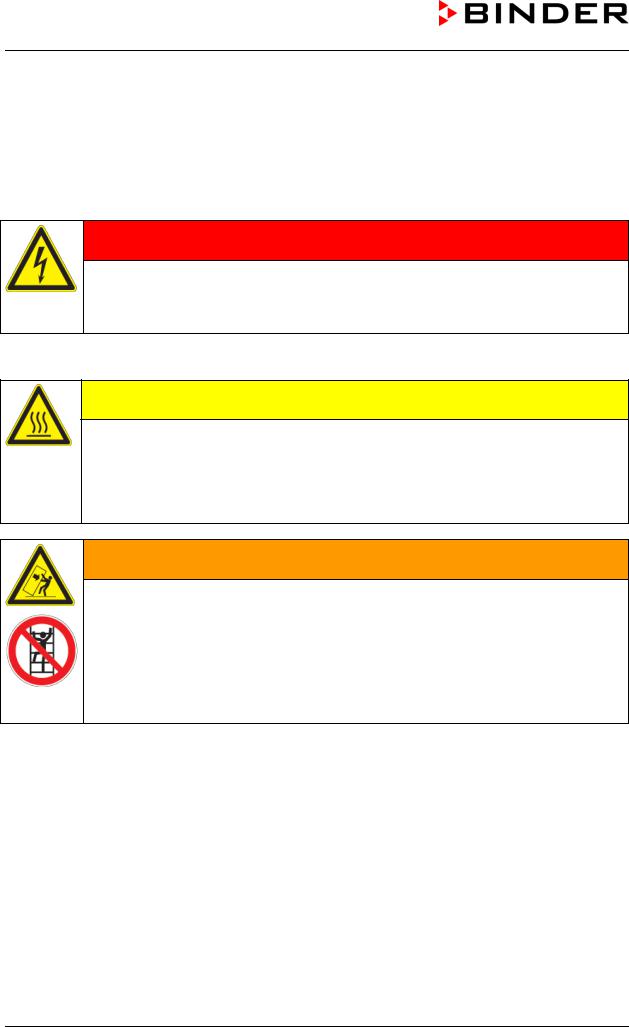
 CAUTION
The inner chamber, the door window and the access ports will become hot during operation.
Danger of burning.
Do NOT touch the inner surfaces, the door window, the access ports, or the charging material during operation.
 WARNING
Stability hazard.
Danger of injury.
Damage to the unit and the charging material.
Housing cover breakaway.
Do NOT climb the lower housing cover.
Do NOT load the lower housing cover with heavy objects while the unit door is open.
MK (E2.1) 10/2014 |
page 13/73 |

1.6Intended use
The alternating climate chamber MK is suitable for temperature treatment of solid or pulverized charging material, as well as bulk material, using the supply of heat or cold. It is suitable for harmless materials. A mixture of any component of the charging material with air must NOT be explosive. The operating temperature must lie below the flash point or below the sublimation point of the charging material. Any component of the charging material must NOT be able to release toxic gases.
Other applications are not approved.
The alternating climate chamber MK can be used for drying purposes but are specially designed for solving all the problems which occur during material and ageing tests.
Do NOT use the unit for drying purpose, especially if greater quantities of steam leading to condensation will be set free.
Observing the instructions in this operating manual and conducting regular maintenance work (chap. 15) is part of the intended use.
 DANGER
Explosion or implosion hazard.
Danger of poisoning.
Danger of death.
Do NOT introduce any substance combustible or explosive at working temperature into the alternating climate chamber.
NO explosive dust or air-solvent mixture in the inner chamber.
Do NOT introduce any substance which could lead to release of toxic gases.
The charging material shall not contain any corrosive ingredients that may damage the machine components made of stainless steel, aluminum, and copper. Such ingredients include in particular acids and halides. Any corrosive damage caused by such ingredients is excluded from liability by BINDER GmbH.
MK (E2.1) 10/2014 |
page 14/73 |

2.Unit description
The alternating climate chamber MK is a specially developed precision refrigerating / warming cabinet with an unrivalled capacity, which by far exceeds the capabilities of normal test cabinets. With its extensive program control, the alternating climate chamber MK is designed for optimum performance with regard to temperature accuracy and rapid heating up and cooling down phases, thus providing the ideal facilities for solving all the problems which occur during material as well as ageing and stress tests. In addition, the alternating climate chamber MK provides almost unlimited possibilities for adaptation to individual customer requirements based upon extensive programming options.
The patented APT.line™ preheating chamber and air conduction technology guarantees excellent spatial temperature values for the total working area. The alternating climate chamber MK provides a powerful refrigerating system with rapid cooling-down speeds. In addition, the alternating climate chamber MK provides almost unlimited possibilities for adaptation to individual customer requirements based upon extensive programming options.
The high-quality housing insulation guarantees both a low noise mode of operation and a consistently low housing temperature. The inner chamber, the pre-heating chamber and the interior side of the doors are all made of stainless steel V2A (German material no. 1.4301, US equivalent AISI 304). When operating the chamber at temperatures above 150 °C / 302°F, the impact of the oxygen in the air may cause discoloration of the metallic surfaces (yellowish-brown or blue) by natural oxidation processes. These colorations are harmless and will in no way impair the function or quality of the unit. The housing is RAL 7035 powder-coated. All corners and edges are also completely coated.
All unit functions are easy and comfortable to use thanks to their clear arrangement. Major features are easy cleaning of all unit parts and avoidance of undesired contamination.
The efficient program controller is equipped with a multitude of operating functions, in addition to recorder and alarm functions. Programming of test cycles is easily accomplished via the modern color-display controller MB1 and is also possible directly with a computer via Intranet in connection with the communication software APT-COM™ 3 DataControlSystem. The alternating climate chamber MK is regularly equipped with a serial interface RS 422 for computer communication, e.g. with the communication software APTCOM™, which permits networking up to 30 units and connecting them to a PC for controlling and programming, as well as recording and representing temperature data 3 DataControlSystem (option, chap. 14.1) For further options, see chap. 18.5.
At an ambient temperature of +18 °C / 64.4 °F to +32 °C / 89.6 °F, you can operate the alternating climate chamber MK in a temperature range from -40 °C / -40 °F up to +180 °C / 356 °F.
MK (E2.1) 10/2014 |
page 15/73 |

2.1Unit overview
(A)
(B)
(C)
(D)
(E)
Figure 3: Alternating climate chamber MK 53
(A)Instrument box
(B)Door handle
(C)Inspection window
(D)Unit door
(E)Refrigerating machine
2.2Instrument box MK
(1)
(2)
Figure 4: Triangle instrument box MK
(1)Microprocessor program controller MB1
(2)Main power switch ON/OFF
MK (E2.1) 10/2014 |
page 16/73 |
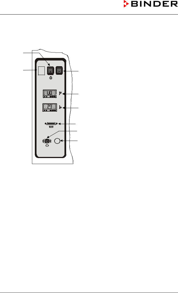
2.3Lateral control panel MK
(4) |
|
(3) |
(5) |
|
RESET CL. 2.0 |
(6a)
(6b)
(7)
(8)
(9)
Figure 5: Lateral control panel at the left side of the refrigerating machine with options over-/under temperature safety device, and analog output
(3)Free place for optional button
(4)Switch for interior chamber light on / off
(5)RESET button for option over-/under temperature safety device class 2 (option, chap. 11.3)
(6)Over-/under temperature safety device (option, chap. 11.3) (6a) Module for upper temperature limit
(6b) Module for lower temperature limit
(7)RS 422 serial interface for computer communication
(8)Analog output (option)
The current temperature value is put out as analogue signal 4-20 mA to a DIN socket. Measuring range 4 mA = -40 °C, 20 mA = +180 °C.
(9)Not used
MK (E2.1) 10/2014 |
page 17/73 |

3.Completeness of delivery, transportation, storage, and installation
3.1Unpacking, and checking equipment and completeness of delivery
After unpacking, please check the unit and its optional accessories, if any, based on the delivery receipt for completeness and for transportation damage. Inform the carrier immediately if transportation damage has occurred.
The final tests of the manufacturer may cause traces of the shelves on the inner surfaces. This has no impact on the function and performance of the unit.
Please remove any transportation protection devices and adhesives in/on the unit and on the doors and take out the operating manuals and accessory equipment.
 CAUTION
Sliding or tilting of the unit.
Damage to the unit.
Risk of injury by lifting heavy loads.
Do NOT lift or transport the unit using the door, the handle or the lower housing.
Lift the unit from the pallet at its four lower corners with the aid of four people.
If you need to return the unit, please use the original packing and observe the guidelines for safe lifting and transportation (chap. 3.2).
For disposal of the transport packing, see chap. 16.1.
Note on second-hand units (Ex-Demo-Units):
Second-hand units are units that were used for a short time for tests or exhibitions. They are thoroughly tested before resale. BINDER ensures that the chamber is technically sound and will work flawlessly.
Second-hand units are marked with a sticker on the unit door. Please remove the sticker before commissioning the unit.
MK (E2.1) 10/2014 |
page 18/73 |

3.2Guidelines for safe lifting and transportation
After operation please observe the guidelines for temporarily decommissioning the unit (chap. 16.2).
 CAUTION
Sliding or tilting of the unit.
Damage to the unit.
Risk of injury by lifting heavy loads.
Transport the unit only in its original packaging.
Secure the alternating climate chamber with transport straps for transport.
Do NOT lift or transport the unit using the door handle, the door or the lower housing.
Lift he unit at its four lower corners with the aid of 4 people and place it on a transport pallet with wheels. Push the pallet to the desired site and then lift the unit at its four lower corners from the pallet..
•Permissible ambient temperature range during transport: -10 °C / 14 °F to +60 °C / 140 °F.
You can order transport packing and pallets for moving or shipping purposes from BINDER service.
3.3Storage
Intermediate storage of the unit is possible in a closed and dry room. Observe the guidelines for temporary decommissioning (chap. 16.2).
•Permissible ambient temperature range during storage: -10 °C / 14 °F to +60 °C / 140 °F.
•Permissible ambient humidity: max. 70 % r.H., non-condensing
When after storage in a cold location you transfer the unit to its warmer installation site, condensation may form. Before start-up, wait at least two hours until the chamber has attained ambient temperature and is completely dry and the oil in the compressors has warmed up.
In case of a prolonged temporal decommissioning: Leave the unit door open or remove the access port plugs.
3.4Location of installation and ambient conditions
Set up the alternating climate chamber on a flat, even and non-flammable surface, free from vibration, and in a well-ventilated, dry location and align it using a spirit level. The site of installation must be capable of supporting the unit’s weight (see technical data, chap. 18.4). The chambers are designed for setting up inside a building (indoor use).
When after storage in a cold location you transfer the unit to its warmer installation site, condensation may form. Before start-up, wait at least two hours until the chamber has attained ambient temperature and is completely dry and the oil in the compressors has warmed up.
CAUTION
Danger of overheating.
Damage to the unit.
Do NOT set up units in non-ventilated recesses.
Ensure sufficient ventilation for dispersal of the heat.
MK (E2.1) 10/2014 |
page 19/73 |

Permissible ambient temperature range during operation: +18 °C / 64.4 °F to +32 °C / 89.6 °F. At elevated ambient temperature values, fluctuations in temperature can occur.
The ambient temperature should not be substantially higher than the indicated ambient temperature of +25 °C / 77 °F to which the specified technical data relate. For other ambient conditions, deviations from the indicated data are possible.
• Permissible ambient humidity: 70 % r.H. max., non-condensing.
When operating the chamber at temperature set-points below ambient temperature, high ambient humidity may lead to condensation on the unit.
• Installation height: max. 2000 m / 6562 ft. above sea level.
When placing several units of the same size side by side, maintain a minimum distance of 250 mm / 9.84 in between each unit. Wall distances: rear 100 mm / 3.94 in, sides 160 mm / 6.31 in. Spacing above the unit of at least 100 mm / 3.94 in must also be maintained.
CAUTION
Danger by stacking. Damage to the units.
Do NOT place alternating climate chambers on top of each other.
To completely separate the unit from the power supply, you must disconnect the power plug. Install the unit in a way that the power plug is easily accessible and can be easily pulled in case of danger.
With an increased amount of dust in the ambient air, clean the condenser fan (by suction or blowing) several times a year.
Avoid any conductive dust in the ambiance according to the unit layout complying with pollution degree 2 (IEC 61010-1).
Do not install or operate the alternating climate chamber MK in potentially explosive areas.
 DANGER
Explosion hazard.
Danger of death.
Do NOT operate the unit in potentially explosive areas.
KEEP explosive dust or air-solvent mixtures AWAY from the vicinity of the unit.
MK (E2.1) 10/2014 |
page 20/73 |
4.Installation and connections
4.1Electrical connection
The alternating climate chamber MK is supplied ready for connection.
•Shockproof plug, power supply voltage 230 V (1N~) +/- 10 %, 50 Hz Fixed power connection cable 1800 mm / 5.9 ft in length
•The socket must also provide a protective conductor.
•Prior to connection and start-up, check the power supply voltage. Compare the values to the specified data located on the unit’s type plate (unit front behind the door, bottom left-hand, chap. 1.4)
•When connecting, please observe the regulations specified by the local electricity supply company and as well as the VDE directives (for Germany). We recommend the use of a residual current circuit breaker.
•Pollution degree (acc. to IEC 61010-1): 2
•Over-voltage category (acc. to IEC 61010-1): II
CAUTION
Danger of incorrect power supply voltage.
Damage to the equipment.
Check the power supply voltage before connection and start-up.
Compare the power supply voltage with the data indicated on the type plate.
See also electrical data (chap. 18.4).
To completely separate the unit from the power supply, you must disconnect the power plug. Install the unit in a way that the power plug is easily accessible and can be easily pulled in case of danger.
MK (E2.1) 10/2014 |
page 21/73 |

5.Start up
After connecting the electrical supply (chap. 4), turn on the unit by the main power switch (2).
Warming chambers may release odors in the first few days after commissioning. This is not a quality defect. To reduce odors quickly we recommend heating up the chamber to its nominal temperature for one day and in a well-ventilated location.
5.1Function overview of display program controller MB1
Pilot lamp: Ready for operation
EXIT button (to exit a menu point)
AUTOMATIC button (to start a previously entered program)
ENTER button (to confirm a selection)
Navigation buttons (functions are assigned by the menu)
Main power switch (2)
Figure 6: Display program controller MB1
The program controller MB1 controls the temperature inside the alternating climate chamber.
You can enter the desired set point values in Manual Mode or Program Mode (chap. 5.2) in the display controller.
08:43:55 |
15.12.05 |
X |
|
W |
TEMP |
40.0 |
36.8 °C |
|
|
HAND
CONFIG |
PGM |
VIEW-> |
Set point value |
Actual value |
Figure 7: Normal display of the MB1 program controller in Manual mode
MK (E2.1) 10/2014 |
page 22/73 |
Loading...