


Operating Manual
APT.line® FP
Heating/drying ovens with program control and forced convection
with microprocessor program controller RD3
BINDER GmbH
Address |
Post office box 102 |
|
|
D-78502 Tuttlingen |
|
Tel. |
+49 |
7462 2005 0 |
Fax |
+49 |
7462 2005 93 0 |
Internet |
http://www.binder-world.com |
|
info@binder-world.com |
||
Service Hotline |
+49 |
7462 2005 555 |
Service Fax |
+49 |
7462 2005 93 555 |
Service E-Mail |
service@binder-world.com |
|
Service Hotline USA |
+1 866 816 8191 |
|
Service Hotline Asia Pacific |
+603 6204 2855 |
|
|
|
|
Issue 01/2006 |
|
Art. No. 7001-0080 |
|
|
|

EG - KONFORMITÄTSERKLÄRUNG
EC - DECLARATION OF CONFORMITY
CE - DECLARATION DE CONFORMITE
Anbieter / Supplier / Fournisseur: |
BINDER GmbH |
Anschrift / Address / Adresse : |
Im Mittleren Ösch 5, D-78532 Tuttlingen |
Produkt / Product / Produit: |
Wärme-/Trockenschränke mit Programmregelung und forcierter |
|
Umluft |
|
Heating/drying ovens with program control and forced convection |
|
Etuves universelles à régulation programmable et circulation d’air |
|
forcée |
Typenbezeichnung / Type / Type |
FP 53, FP 115, FP 240, FP 400, FP 720 |
Die oben beschriebenen Produkte sind konform mit folgenden harmonisierten Normen: The products described above are in conformity with the following harmonized standards: Les produits décrits ci-dessus sont conformes aux normes harmonisées suivantes:
Sicherheit / safety / sécurité: |
|
IEC/CEI 61010-1:2001 |
Sicherheitsbestimmungen für elektrische Mess-, Steuer-, Regel- |
|
und Laborgeräte – Teil 1: Allgemeine Anforderungen |
|
Safety requirements for electrical equipment for measurement, |
|
control, and laboratory use – Part 1: General requirements |
|
Règles de sécurité pour appareils électriques de mesurage, de |
|
régulation et de laboratoire – Partie 1 : Prescriptions générales |
IEC/CEI 61010-2-010:2003 |
Sicherheitsbestimmungen für elektrische Meß-, Steuer-, Regel- |
|
und Laborgeräte – Teil 2-010: Besondere Anforderungen an |
|
Laborgeräte für das Erhitzen von Stoffen |
|
Safety requirements for electrical equipment for measurement, |
|
control, and laboratory use – Part 2-010: Particular requirements |
|
for laboratory equipment for the heating of materials |
|
Règles de sécurité pour appareils électriques de mesurage, de |
|
régulation et de laboratoire. Partie 2-010 : Prescriptions |
|
particulières pour appareils de laboratoire utilisés pour |
|
l’échauffement des matières |
EMV / EMC / CEM: |
|
IEC/CEI 61326:1997 + A1:1998 + |
Elektrische Betriebsmittel für Leittechnik und Laboreinsatz – EMV- |
A2:2000 |
Anforderungen |
|
Electrical equipment for measurement, control and laboratory use |
|
– EMC requirements |
|
Matériels électriques de mesure, de commande et de laboratoire |
|
– Prescriptions relatives à la CEM |
1 / 2
FP 01/2006 |
page 2/52 |

Die oben beschriebenen Produkte sind konform mit folgenden EG-Richtlinien: The products described above are in conformity with the following EC guidelines: Les produits décrits ci-dessus sont conformes aux directives CE suivantes:
Niederspannungsrichtlinie 73/23/EWG, Änderung 93/68/EWG
Low voltage directive 73/23/EEC, amended 93/68/EEC
Directive basse tension 73/23/CEE, modifiée 93/68/CEE
EMV-Richtlinie
89/336/EWG, Änderung 93/68/EWG
EMC Directive
89/336/EEC, amended 93/68/EEC
Directive CEM
89/336/CEE, modifiée 93/68/CEE
Richtlinie 73/23/EWG des Rates vom 19. Februar 1973 zur Angleichung der Rechtsvorschriften der Mitgliedstaaten betreffend elektrische Betriebsmittel zur Verwendung innerhalb bestimmter Spannungsgrenzen
Council Directive of 19 February 1973 on the harmonization of the laws of Member States relating to electrical equipment designed for use within certain voltage limits (73/23/EEC)
Directive 73/23/CEE du Conseil, du 19 février 1973, concernant le rapprochement des législations des États membres relatives au matériel électrique destiné à être employé dans certaines limites de tension
Richtlinie 89/336/EWG des Rates vom 3. Mai 1989 zur Angleichung der Rechtsvorschriften der Mitgliedstaaten über die elektromagnetische Verträglichkeit
Council Directive 89/336/EEC of 3 May 1989 on the approximation of the laws of the Member States relating to electromagnetic compatibility
Directive 89/336/CEE du Conseil du 3 mai 1989 concernant le rapprochement des législations des États membres relatives à la compatibilité électromagnétique
Die oben beschriebenen Produkte tragen entsprechend die Kennzeichnung CE. The products described above, corresponding to this, bear the CE-mark
Les produits décrits ci-dessus, en correspondance, portent l’indication CE.
D-78532 Tuttlingen, 10.01.2006
BINDER GmbH
P. M. Binder |
Dr.-Ing. V. Kek |
Geschäftsführender Gesellschafter |
Leiter F & E |
Managing Director |
Head of R & D |
Directeur général |
Chef de service R&D |
2 / 2
FP 01/2006 |
page 3/52 |

Contents |
|
|
1. |
SAFETY.................................................................................................................. |
6 |
1.1 |
Legal considerations ........................................................................................................................... |
6 |
1.2 |
Structure of the safety instructions...................................................................................................... |
6 |
1.3 |
Localization / position of safety labels at the unit................................................................................ |
8 |
1.4 |
Type plate ........................................................................................................................................... |
9 |
1.5 |
General safety instructions on installing and operating the heating/drying oven FP........................ |
10 |
1.6 |
Intended use ..................................................................................................................................... |
11 |
2. |
WARRANTY......................................................................................................... |
12 |
3. |
UNIT DESCRIPTION ............................................................................................ |
13 |
3.1 |
Unit overview..................................................................................................................................... |
14 |
3.2 |
Control panel..................................................................................................................................... |
15 |
4.SCOPE OF DELIVERY, TRANSPORTATION, STORAGE, AND INSTALLATION15
4.1 |
Unpacking, and checking equipment and scope of delivery............................................................. |
15 |
4.2 |
Advice for safe lifting and transportation........................................................................................... |
16 |
4.3 |
Storage.............................................................................................................................................. |
16 |
4.4 |
Location of installation and ambient conditions ................................................................................ |
16 |
5. |
INSTALLATION OF THE EQUIPMENT ............................................................... |
17 |
5.1 |
Electrical connection ......................................................................................................................... |
17 |
5.2 |
Connection to a suction plant (optional) ........................................................................................... |
18 |
6. |
START UP............................................................................................................ |
18 |
6.1 |
Air change ......................................................................................................................................... |
18 |
6.2 |
Settings at the RD3 program controller ............................................................................................ |
19 |
6.3 |
General indications ........................................................................................................................... |
20 |
7. |
FIXED VALUE ENTRY MODE ............................................................................. |
21 |
8. |
PROGRAM EDITOR............................................................................................. |
22 |
8.1 |
Selecting between set-point ramp and set-point step....................................................................... |
22 |
8.2 |
Set-point entry for program operation............................................................................................... |
24 |
8.3 |
Program table template..................................................................................................................... |
28 |
8.4 |
Deleting a program section ............................................................................................................... |
29 |
9. |
PROGRAM START LEVEL.................................................................................. |
30 |
10. |
USER LEVEL ....................................................................................................... |
32 |
11. |
BEHAVIOR AT FAILURES .................................................................................. |
36 |
11.1 |
Behavior after power failure .............................................................................................................. |
36 |
11.2 |
Alarm messages ............................................................................................................................... |
36 |
12. |
TEMPERATURE SAFETY DEVICES................................................................... |
36 |
12.1 |
Temperature safety device class 2 (DIN 12880) .............................................................................. |
36 |
12.2 |
Temperature safety device class 3.1 (DIN 12880) (option) .............................................................. |
37 |
13. |
OPTIONS.............................................................................................................. |
38 |
13.1 |
Communication software APT-COM® 3 DataControlSystem (option) .............................................. |
38 |
13.2 |
Protocol printer (option) .................................................................................................................... |
39 |
13.3 |
HEPA fresh air filter (option) ............................................................................................................. |
39 |
FP 01/2006 |
page 4/52 |

13.4 |
Additional measuring channel for digital object temperature indicator with flexible temperature |
|
|
sensor Pt 100 (option)....................................................................................................................... |
40 |
13.5 |
Analog output for temperature (option)............................................................................................. |
40 |
13.6 |
Zero-voltage relay outputs via operation lines (option)..................................................................... |
40 |
13.7 |
Mostly gas-tight version (option for FP 53 and FP 115) ................................................................... |
41 |
13.8 |
Inert gas connection (option for FP 53 and FP 115)......................................................................... |
41 |
14. |
MAINTENANCE, CLEANING, AND SERVICE .................................................... |
42 |
14.1 |
Maintenance intervals, service.......................................................................................................... |
42 |
14.2 |
Cleaning and decontamination ......................................................................................................... |
42 |
15. |
DISPOSAL............................................................................................................ |
44 |
15.1 |
Disposal of the transport packing ..................................................................................................... |
44 |
15.2 |
Decommissioning.............................................................................................................................. |
44 |
15.3 |
Disposal of the unit............................................................................................................................ |
44 |
16. |
TECHNICAL DESCRIPTION................................................................................ |
45 |
16.1 |
Factory calibration and adjustment................................................................................................... |
45 |
16.2 |
Over current protection ..................................................................................................................... |
45 |
16.3 |
Definition of usable space................................................................................................................. |
45 |
16.4 |
Technical data................................................................................................................................... |
46 |
16.5 |
Equipment and Options .................................................................................................................... |
47 |
16.6 |
Spare parts........................................................................................................................................ |
49 |
17. |
CONTAMINATION CLEARANCE CERTIFICATE ............................................... |
50 |
FP 01/2006 |
page 5/52 |
Dear customer,
For the proper operation of the heating/drying oven FP, it is necessary to read this operating manual completely and carefully and to observe the given instructions.
1.Safety
This operating manual is part of the scope of delivery. Always keep it at hand.
To avoid injuries and damage observe the safety instructions of the operating manual.
 WARNING
Failure to observe the safety instructions. Serious injuries and unit damage.
Observe the safety instructions in this operating manual.
Carefully read the complete operating instructions of the heating/drying oven FP.
1.1Legal considerations
This operating manual contains information necessary for the intended use, correct installation, start-up and operation, and for the maintenance of the unit.
Understanding and observing the instructions in this operating manual are prerequisites for hazard-free use and safety during operation and maintenance.
This operating manual cannot cover all conceivable applications. If you would like additional information, or if special problems arise that you feel are not sufficiently addressed in this manual, please ask your dealer or contact us directly.
Furthermore, we note that the contents of this operating manual are not part of an earlier or existing agreement, promise, or legal relationship, nor do they modify such a relationship. All obligations on the part of BINDER derive from the respective purchase contract, which also contains the entire and exclusively valid statement of warranty administration. The statements in this manual neither augment nor restrict the contractual warranty provisions.
1.2Structure of the safety instructions
In this operating manual, the following harmonized denominations and symbols indicate dangerous situations in accordance with ISO 3864-2 and ANSI Z535.4.
Signal word panel
Depending on seriousness and probability of the consequences, dangers are identified with a signal word, the corresponding safety color, and if appropriate, the safety alert symbol.
 DANGER
Indicates an imminently hazardous situation that, if not avoided, will result in death or serious (irreversible) injury.
 WARNING
Indicates a potentially hazardous situation which, if not avoided, could result in death or serious (irreversible) injury.
FP 01/2006 |
page 6/52 |

 CAUTION
Indicates a potentially hazardous situation which, if not avoided, may result in moderate or minor (reversible) injury.
CAUTION
Indicates a potentially hazardous situation which, if not avoided, may result in damage of the product and/or its functions or of a property in its ambiance.
Safety alert symbol
Use of the safety alert symbol indicates risk of injury.
Observe all measures that are marked with the safety alert symbol in order to avoid death or injury.
Pictograms
Warning signs
|
Electrical hazard. |
|
Explosive substances |
|
|
|
|
|
Hot surface |
|
Inhalation hazard |
|
|
|
|
|
Tipover hazard |
|
Pollution Hazard |
|
|
|
|
Mandatory action signs |
|
|
|
|
Mandatory regulation |
|
Lift with several persons |
|
|
|
|
|
Read operating instructions |
|
Lift with mechanical assistance |
|
|
|
|
|
Pull the power plug |
|
Environment protection |
|
|
|
|
Prohibition signs
|
Do NOT touch |
|
Do NOT spray with water |
|
|
|
|
FP 01/2006 |
page 7/52 |

Information to be observed in order to ensure optimum function of the product.
Word message panel structure
Type / cause of hazard.
Possible consequences.
Instruction how to avoid the hazard: prohibition Instruction how to avoid the hazard: mandatory action
Observe the other notes and information not specially emphasized in the same way, in order to avoid disturbances which could result in direct or indirect injuries or property damage.
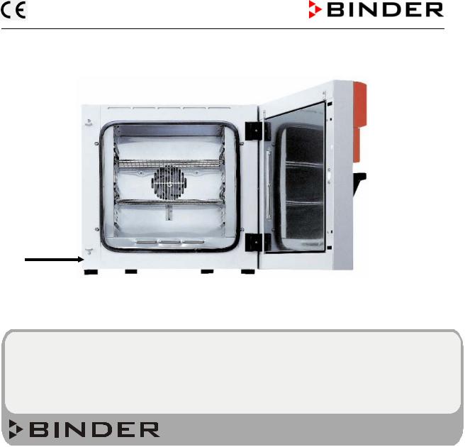
1.3Localization / position of safety labels at the unit
Following labels are located on the unit:
Pictograms (Warning signs) |
Service label |
Hot surface
Figure 1: Position of labels at the unit |
|
Keep safety labels complete and legible. |
|
FP 01/2006 |
page 8/52 |
1.4Type plate
|
|
|
Figure 2: Position of type plate |
|
||
|
|
|
|
|||
Nenntemperatur |
300°C |
1,60 kW |
|
|||
|
572°F |
230 V 1 N ~ |
|
|||
Schutzart |
IP 20 |
7,0 A |
|
|||
Temp. Schutz |
DIN 12880 |
50/60 Hz |
|
|
|
|
|
|
|||||
Klasse |
2.0 |
|
|
|
|
|
Artikel-Nr. |
9020-0227 |
US PATS 4585923 / 5222612 / 5309981 |
|
|
|
|
|
|
|||||
Projekt-Nr. |
|
|
5405194 / 5601143 / 5773287 / 6079403 |
|
|
|
|
|
|
D 78532 Tuttlingen / Germany |
FP 115 # 00-00000 |
||
|
|
|
Tel. + 49 (0) 7462 / 2005-0 |
Made in Germany |
||
Internet: www.binder-world.com
Figure 3: Type plate (example of FP 115 regular unit)
Indications of the type plate |
Information |
|
Nenntemperatur |
300°C |
Nominal temperature |
|
572°F |
|
Schutzart |
IP 20 |
IP type of protection 20 acc. to EN 60529 |
Temp. Schutz |
DIN 12880 |
Temperature safety device acc. to standard DIN 12880 |
Klasse |
2.0 |
Temperature safety device, class 2 |
Artikel-Nr. |
9020-0227 |
Art. No. 9020-0227 |
Projekt-Nr. |
--- |
(Special application acc. to project no.) |
|
1,60 kW |
Nominal power 1.60 kW |
|
230 V 1 N ~ |
Nominal voltage 230 V ± 10%, single-phase unit |
|
7,0 A |
Nominal current 7.0 Amp |
|
50/60 Hz |
Mains frequency 50/60 Hz |
FP 115 |
|
Model FP 115 |
# 00-00000 |
|
Serial No. 00-00000 |
FP 01/2006 |
page 9/52 |

1.5General safety instructions on installing and operating the heating/drying oven FP
With regard to operating the heating/drying oven FP and to the installation location, please observe the regulations BGR 120 of the German professional association of the chemical industry (formerly ZH 1/119 laboratory guidelines of the employers’ liability insurance association) (for Germany).
The BINDER GmbH is responsible for safety-related unit properties only if skilled electricians or qualified personnel authorized by BINDER perform all maintenance and repair, and if components relating to chamber safety are replaced in case of failure with original spare parts.
To operate the unit, use only original BINDER accessories or accessories of third-party suppliers authorized by BINDER. The user is responsible for any risk when using unauthorized accessories.
CAUTION
Danger of overheating.
Damage of the unit.
Do not install the unit in unventilated recesses. Ensure sufficient ventilation for carrying-off the heat.
The heating/drying oven FP must NOT be operated in hazardous locations.
 DANGER
Explosion hazard.
Danger of life.
Do NOT operate the unit in potentially explosive areas.
NO explosive dust or air-solvent mixture in the ambiance.
The heating/drying oven FP does not dispose of any measures of explosion protection.
 DANGER
Explosion hazard.
Danger of life.
Do NOT introduce any substance combustible or explosive at working temperature into the heating/drying oven.
NO explosive dust or air-solvent mixture in the inner chamber.
Any solvent contained in the charging material must not be explosive or inflammable. I.e., irrespective of the solvent concentration in the steam room, NO explosive mixture with air will form. The temperature inside the chamber must lie below the flash point or below the sublimation point of the charging material. Keep informed about the physical and chemical properties of the charging material, as well as the contained moisture constituent and its behavior under addition of heat energy.
Keep informed about any potential health risks caused by the charging material, the contained moisture constituent or by reaction products which may arise during the temperature process. Take adequate measures to exclude such risks prior to putting the heating/drying oven into operation.
FP 01/2006 |
page 10/52 |
 DANGER
Electrical hazard. Danger of life.
The unit must NOT become wet during operation or maintenance.
The heating/drying ovens have been produced in accordance to the VDE regulations and were routinely tested in accordance to VDE 0411.
 CAUTION
The inner chamber, the outgoing air pipe, the door window (option) and the access ports will become hot during operation.
Danger of burning.
Do NOT touch the inner surfaces, the outgoing air pipe, the door window, the access ports, and the charging material during operation.
1.6Intended use
Heating/drying ovens FP are suitable for drying and heat treatment of solid or pulverized charging material, as well as bulk material, using the supply of heat. The ovens are suitable for harmless charging material. A mixture of any component of the charging material with air must NOT be explosive. The operating temperature must lie below the flash point or below the sublimation point of the charging material.
Other applications are not approved.
Do NOT use the unit for drying purpose, especially if greater quantities of steam leading to condensation will be set free.
Due to the special demands of the Medical Device Directive (MDD), these ovens are not qualified for sterilization of medical devices as defined by the directive 93/42/EWG.
Respecting the instructions in this operating manual and conducting regular maintenance work (chap. 14.1) is part of the intended use.
FP 01/2006 |
page 11/52 |

2.Warranty
BINDER products are manufactured with great care and checked carefully prior to delivery (VDE-piece checked).
1.Should your BINDER product have a material defect or manufacturing fault, we shall repair it – as long as it is a new BINDER product – free of charge if the defect or fault occurs within 12 months after delivery. This period will be extended to 24 months, starting from delivery, provided that all maintenance and potential repair work within the first 12 months is carried out by us or authorized service stations.
2.Should you discover a defect or fault in your BINDER product within the aforementioned period, please inform the company from which you purchased the BINDER product or BINDER directly.
3.All above-mentioned periods or deadlines shall begin with the delivery of a new BINDER product to the end buyer. Producing the invoice or delivery note shall bring evidence of deadline keeping.
4.In case a BINDER product has a defect or fault, we shall either replace the defective product with a new one or repair the defective product at our discretion (so called supplementary performance – “Nacherfüllung”). All parts replaced in the course of such repair shall become our property. Deadlines mentioned under above number 1 shall not be prolonged by repair work or substitution. In case supplementary performance should fail, usual warranty rights according to German Law (withdrawal from contract or price reduction) shall apply, provided the defect or fault occurs within the first 12 months. Should the 24 month-period be relevant and supplementary performance fail, you shall only be entitled to a price reduction.
5.Should the defect occur within 12 months after delivery, we shall take over all costs necessary for the repair of the defect, especially transportation, travel and labor costs, in so far as there is no cost increase due to the product being brought to another location than the place of delivery. However, we shall decide whether the defect will be repaired at the location where the BINDER product is operating or whether the BINDER product has to be sent to us. In case the 24 month-period should be relevant, please send the defective BINDER product at your expense to BINDER or the company from which you purchased the BINDER product. We shall repair the BINDER product at your premises only if transportation costs are excessively high. The customer shall be liable for any risk of sudden destruction or deterioration.
6.Should you have to send back a BINDER product, the BINDER product will have to be supplied in its original packaging or any similar suitable packaging.
7.All warranty claims as laid down in this document basically become invalid:
•if the defect or fault is caused by repair or intervention by non-authorized persons. With authorized persons, we mean only Binder service engineers and service engineers of our service partners.
•the same applies if you have attached non-suitable parts or accessories to the BINDER products, which are not original BINDER spare parts, and if those parts or accessories have caused the defect or fault.
•parts that become used due to natural wear and tear, e.g. door seals, lamps, lights (enumeration not exhaustive)
•defects caused by external intervention like e.g. fall or blow
•defects arising from non-compliance with operating instructions, improper use, abnormal ambient conditions, overload or absence of care/maintenance
•in the case of devices that were converted or redesigned by non-authorized third parties
•in case of minor deviations from the set quality that are irrelevant to the value and usability of the device
8.All rights or claims beyond the ones described above, especially concerning the right of compensation for potential damages which might be caused by BINDER products shall be excluded provided that such exclusion is not prohibited by governing law.
FP 01/2006 |
page 12/52 |

9.Should you send a BINDER product to us for repair or any other reasons, we shall only accept the BINDER product upon presentation of a so-called authorization number that has previously been issued to you. We shall issue the authorization number after receiving your complaint in writing or via telephone prior to your sending (back) the BINDER product to us. The authorization number will be issued following the receipt of the information mentioned below:
•BINDER product type and serial number
•Date of purchase
•Name and address of the dealer from which you bought the BINDER product
•Exact description of defect or fault
•Your full address; if possible contact person and availability of that person
•Exact location of the BINDER product
•Contamination clearance certificate via fax in advance!
The authorization number needs to be applied to the packaging in such a way that it can be easily recognized or be recorded clearly in the delivery documents. For security reasons we cannot accept your delivery if it does not carry an authorization number!
IMPORTANT NOTICE:
Any warranty repair maintenance or service work may only be carried out by persons or companies being properly authorized by us. If you do not know an authorized service station, please contact us and we will name you our service partner closest to you. Otherwise, we will carry out the necessary work ourselves.
Date: November 2003
3.Unit description
BINDER heating/drying ovens with forced convection FP are equipped with the electronic program controller RD3 with digital display. This allows programming of temperature cycles and an individual fan speed setting for each program section.
The APT.line® preheating chamber system guarantees high level of spatial and time-based temperature precision, thanks to the direct and distributed air circulation into the interior.
The air turbine supports exact attainment and maintenance of the desired temperature accuracy. The fan speed is digitally adjustable from 0 % to 100%.
All unit functions are easy and comfortable to use thanks to their clear arrangement. Major features are easy cleaning of all unit parts and avoidance of undesired contamination.
The inner chamber, the pre-heating chamber and the inside of the doors are all made of stainless steal (material no. 1.4301 in Germany). The housing is RAL 7035powder-coated. All corners and edges are completely coated.
The heating/drying oven FP is regularly equipped with a serial interface RS 422 for computer communication, e.g. via the communication software APT-COM® 3 DataControlSystem (option, chap. 13.1). For further options, see chap. 16.5.
The model FP 720 is equipped with four castors. Both front castors can be locked by brakes.
The units can be operated in a temperature range of 5°C above ambient temperature up to +300°C.
FP 01/2006 |
page 13/52 |
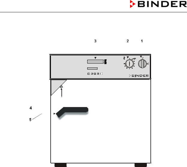
3.1Unit overview
Figure 4: Heating/drying oven FP (example: model FP 53)
(1)Main switch on/Off
(2)Safety device class 2 or class 3.1 (option)
(3)Program controller RD3
(4)Lever for ventilation slide
(5)Door handle
FP 01/2006 |
page 14/52 |
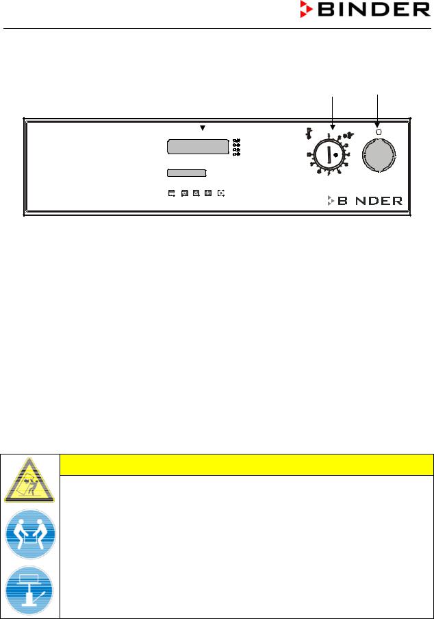
3.2Control panel
(3) |
(2) |
(1) |
|
|
|
|
|
|
|
|
|
|
|
|
|
|
|
|
|
|
|
|
|
|
|
|
|
|
|
|
|
|
|
|
|
|
|
|
|
|
|
|
|
|
|
|
|
|
|
|
|
|
|
|
|
|
|
|
|
|
|
|
|
|
|
|
|
|
|
|
|
|
|
|
|
|
|
|
|
|
|
|
|
|
|
|
|
|
|
|
|
|
|
|
|
|
|
Figure 5: Control panel of standard unit
(1)Main on/off switch
(2)Safety device class 2
(3)Program controller RD3
4.Scope of delivery, transportation, storage, and installation
4.1Unpacking, and checking equipment and scope of delivery
After having unpacked, please check the unit and its optional accessories, if any, based on the delivery note for completeness and for transportation damage. If transportation damage has occurred, immediately inform the carrier.
Please remove any transportation protection devices and adhesives in / on the unit and at the doors and take out the operating manuals and accessory equipment.
CAUTION
Sliding or tilting of the unit.
Damage of the unit.
Do NOT lift or transport the unit using either the door handle or the door.
Do NOT lift units 400 and 720 by hand.
Lift units 53, 115, and 240 near the 4 unit feet from the pallet by aid of 4 persons.
Lift units 400 and 720 using technical devices (fork lifter) from the pallet. Set the fork lifter only from the rear in the middle of the unit. Make sure to place all the lateral supports of the unit on the forks.
If necessary to send back the unit, please use the original packing and respect the advice for safe lifting and transportation (chap. 4.2).
For disposal of the transport packing, see chap. 15.1.
FP 01/2006 |
page 15/52 |

4.2Advice for safe lifting and transportation
The front castors of units 720 can be blocked by brakes. Respect the advice for temporal decommissioning (chap. 15.2).
CAUTION
Sliding or tilting of the unit.
Damage of the unit.
Transport the unit only in its original packaging.
Secure the unit with transport straps for transport.
Do NOT lift or transport the unit using either the door handle or the door.
Do NOT lift units 400 and 720 by hand.
Lift units size 53, 115, and 240 near the 4 unit feet by aid of 4 persons and place it on a transport pallet with wheels. Push the pallet to the desired site and then lift the unit near the 4 unit feet from the pallet.
Place units size 400 and 720 using technical devices (fork lifter) on the transport pallet. Set the fork lifter only from the rear in the middle of the unit. Make sure to place all the lateral supports of the unit on the forks.
Transport units size 400 and 720 ONLY with the original transport pallet. Set the fork lifter only to the pallet. Without the pallet the unit is in imminent danger of overturning.
•Permissible ambient temperature range: -10°C to +60°C.
You can order transport packing and pallets for transport purpose at the BINDER Service.
4.3Storage
Intermediate storage of the unit is possible in a closed and dry room. Respect the advice for temporal decommissioning (chap. 15.2).
•Permissible ambient temperature range: -10°C to +60°C.
•Permissible ambient humidity: max. 70 % r.H., non-condensing
If following storage in a cold location the unit is transferred to the installation site for start-up, condensation is possible. Wait at least one hour until the chamber has attained ambient temperature and is completely dry.
4.4Location of installation and ambient conditions
Set up the heating/drying oven FP on a plane and non-flammable surface, free from vibration at a wellventilated, dry location and align it using a spirit level. The site of installation must be capable of supporting the unit’s weight (see technical data, chap. 16.4).
CAUTION
Danger of overheating.
Damage of the unit.
Do NOT set up units in non-ventilated recesses. Ensure sufficient ventilation for carrying-off the heat.
FP 01/2006 |
page 16/52 |
 Loading...