


BD 56
Table of contents
 Loading...
Binder BD 56, BF 56, BF 115, BD 115, BF 260 Operating Manual
...
BD (E3.1)
Incubators
BF (E3.1)
| Incubators
ED (E3.1)
Drying and heating ovens
FD (E3.1)
| Drying and heating ovens
FED (E3.1)
Drying and heating ovens
and enhanced timer functi ons
Operating Manual
|
|
|
Avantgarde.Line with natural convection
Avantgarde.Line with forced convection
Avantgarde.Line with natural convection
Avantgarde.Line with forced convecti on
Avantgarde.Line with forced convecti on
with microprocessor temperature controller
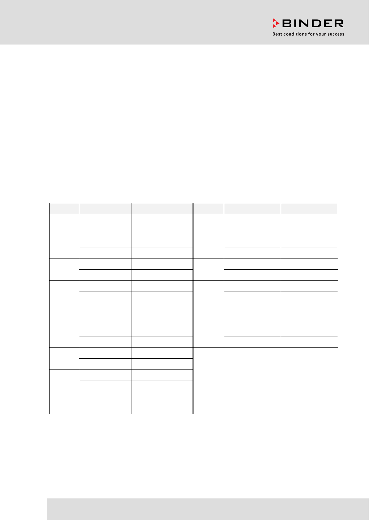
Model Model version Art. No. Model Model version Art. No.
BD 56
BD 115
BD 260
BF 56
BD056-230V 9010/ 9110-0323
FD 56
BD056UL-120V 9010/ 9110-0324 FD056UL-120V 9010/ 9110-0304
BD115-230V 9010/ 9110-0325
FD 115
BD115UL-120V 9010/ 9110-0326 FD115UL-120V 9010/ 9110-0306
BD260-230V 9010/ 9110-0329
FD 260
BD260UL-120V 9010/ 9110-0330 FD260UL-240V 9010/ 9110-0310
BF056-230V 9010/ 9110-0313
FED 56
BF056UL-120V 9010/ 9110-0314 FED056UL-120V 9010/ 9110-0296
FD056-230V 9010/ 9110-0303
FD115-230V 9010/ 9110-0305
FD260-230V 9010/ 9110-0309
FED056-230V 9010/ 9110-0295
BF 115
BF 260
ED 56
ED 115
ED 260
BF115-230V 9010/ 9110-0315
FED 115
BF115UL-120V 9010/ 9110-0316 FED115UL-120V 9010/ 9110-0294
BF260-230V 9010/ 9110-0319
FED 260
BF260UL-120V 9010/ 9110-0320 FED260UL-240V 9010/ 9110-0300
ED056-230V 9010/ 9110-0333
ED056UL-120V 9010/ 9110-0334
ED115-230V 9010/ 9110-0335
ED115UL-120V 9010/ 9110-0336
ED260-230V 9010/ 9110-0339
ED260UL-240V 9010/ 9110-0340
FED115-230V 9010/ 9110-0293
FED260-230V 9010/ 9110-0299
BINDER GmbH
Address: Post office box 102, 78502 Tuttlingen, Germany Phone: +49 7462 2005 0
Fax: +49 7462 2005 100 Internet: http://w ww.b ind er -world.com
E-mail: info@binder-world.com Service Hotline: +49 7462 2005 555
Service Fax: +49 7462 2005 93 555 Service E-Mail: service@binder-world.com
Service Hotline USA: +1 866 885 9794 or +1 631 224 4340 x3
Service Hotline Asia Pacif ic: +852 390 705 04 or +852 390 705 03
Service Hotline Russia and CIS: +7 495 988 15 16
Issue 07/2017 Art. No. 7001-0292

Content
1. SAFETY .................................................................................................................. 5
1.1 Legal considerations ........................................................................................................................... 5
1.2 Structure of the safety instructions ...................................................................................................... 5
1.2.1 Signal word panel ...................................................................................................................... 5
1.2.2 Safety alert symbol .................................................................................................................... 6
1.2.3 Pictograms ................................................................................................................................. 6
1.2.4 Word message panel structure ................................................................................................. 7
1.3 Localization / position of safety labels on the chamber ...................................................................... 7
1.4 Type plate............................................................................................................................................ 8
1.5 General safety instructions on installing and operating the chambers ............................................... 9
1.6 Intended use ..................................................................................................................................... 11
2. CHAMBER DESCRIPTION .................................................................................. 12
2.1 Chamber overview ............................................................................................................................ 12
2.2 Triangular instrument panel .............................................................................................................. 13
3. COMPLETEN ESS OF DEL IVERY, TRANSPORTATION, STORAGE, AND
INSTALLATION .................................................................................................... 14
3.1 Unpacking, and checking equipment and completeness of delivery ................................................ 14
3.2 Guidelines for safe lifting and transportation ..................................................................................... 14
3.3 Storage .............................................................................................................................................. 15
3.4 Location of installation and ambient conditions ................................................................................ 15
4. INSTALLATION .................................................................................................... 16
4.1 Mounting the tilt protection holders (chambers with window) ........................................................... 16
4.2 Electrical connection ......................................................................................................................... 17
4.3 Connection to a suction plant (optional) ............................................................................................ 18
5. START UP ............................................................................................................ 18
5.1 Behavior when opening the door ...................................................................................................... 18
6. OVERVIEW AND GENERAL SETTINGS ON THE R4 CONTROLLER ............... 19
6.1 Controller overview ........................................................................................................................... 19
6.2 Normal display .................................................................................................................................. 19
6.3 Setting the menu language ............................................................................................................... 20
6.4 Setting date and time ........................................................................................................................ 21
6.5 Selecting the temperature unit .......................................................................................................... 23
6.6 Set-point entry for temperature and fan speed ................................................................................. 24
6.7 Adjusting the air flap position ............................................................................................................ 25
6.8 Changing the passwords for user level and general controller functions ......................................... 26
7. OVERTEMPERATURE PROTECTION ................................................................ 28
7.1 Overtemperature protective device (class 1) .................................................................................... 28
7.2 Safety controller ................................................................................................................................ 29
7.3 Setting the safety controller set-point ................................................................................................ 30
7.4 Alarm message and proceeding in case of an alarm ........................................................................ 31
7.5 Function check .................................................................................................................................. 31
7.6 Disconnectable audible over-temperature alarm (option) ................................................................. 32
8. TIMER FUNCTIONS ............................................................................................. 33
8.1 Selecting the timer function ............................................................................................................... 33
8.2 Timer function “Delayed Off” ............................................................................................................. 34
8.2.1 Entry and activation of the timer run-time and fan setting ....................................................... 34
8.2.2 Turning off the timer function or changing the settings ........................................................... 36
BD / BF / ED / FD / FED (E3.1) 07/2017 page 2/99

8.3
Timer function “Temperature dependent Delayed Off” (BF, FED) .................................................... 38
8.3.1 Entry and activation of the timer run-time, fan setting and set-point entry .............................. 38
8.3.2 Turning off the timer function or changing the settings ........................................................... 40
8.4 Timer function “Delayed On” (BF, FED) ............................................................................................ 41
8.4.1 Entry and activation of the timer run-time and fan setting ....................................................... 41
8.4.2 Changing the settings .............................................................................................................. 43
8.5 Temperature programming example (BF, FED) ............................................................................... 43
9. RAMP FUNCTION ................................................................................................ 44
9.1 General information ........................................................................................................................... 44
9.2 Setting and displaying the ramp function .......................................................................................... 45
9.3 Displaying the effective ramp set-point and changing the target ramp set-point .............................. 46
9.4 Turning off the ramp function ............................................................................................................ 47
10. DATA RECORDING VIA USB INTERFACE ........................................................ 48
10.1 Starting data recording ...................................................................................................................... 48
10.2 Terminating data recording ............................................................................................................... 49
11. NETWORK CONFIGURATION FOR CHAMBERS WITH ETHERNET
INTERFACE ......................................................................................................... 50
12. OPTIONS .............................................................................................................. 53
12.1 Communication software APT-COM™ 3 DataControlSystem (option) ............................................ 53
12.2 Data logger kits (option) .................................................................................................................... 53
12.3 Object temperature display with additional Pt100 temperature sensor (option) ............................... 53
12.4 Analog output for temperature (option) ............................................................................................. 54
12.5 Water protected disconnectable internal socket (option BD, BF) ..................................................... 54
12.6 HEPA fresh air filter (option for FD, FED) ......................................................................................... 55
12.7 Mostly gas-tight version (option for BF, FD, FED) ............................................................................ 55
12.8 Inert gas connection with mostly gas-tight version (option for BF, FD, FED) ................................... 55
13. MAINTENANCE, CLEANING, AND SERVICE .................................................... 57
13.1 Maintenance intervals, service .......................................................................................................... 57
13.2 Cleaning and decontamination ......................................................................................................... 58
13.2.1 Cleaning .................................................................................................................................. 58
13.2.2 Decontamination ...................................................................................................................... 59
13.3 Sending the chamber back to BINDER GmbH ................................................................................. 60
14. DISPOSAL............................................................................................................ 61
14.1 Disposal of the transport packing ...................................................................................................... 61
14.2 Decommissioning .............................................................................................................................. 61
14.3 Disposal of the chamber in the Federal Republic of Germany ......................................................... 61
14.4 Disposal of the chamber in the member states of the EU except for the Federal Republic of
Germany............................................................................................................................................ 62
14.5 Disposal of the chamber in non-member states of the EU ............................................................... 63
15. TROUBLESHOOTING ......................................................................................... 64
16. TECHNICAL DESCRIPTION ................................................................................ 65
16.1 Factory calibration and adjustment ................................................................................................... 65
16.2 Definition of usable volume ............................................................................................................... 65
16.3 Over current protection ..................................................................................................................... 65
16.4 BD technical data .............................................................................................................................. 66
16.5 BF technical data .............................................................................................................................. 67
16.6 ED technical data .............................................................................................................................. 69
16.7 FD technical data .............................................................................................................................. 70
16.8 FED technical data ............................................................................................................................ 72
16.9 Equipment and options (extract) ....................................................................................................... 74
16.10 Accessories and spare parts (extract) .............................................................................................. 75
16.11 Dimensions size 56 ........................................................................................................................... 77
16.12 Dimensions size 115 ......................................................................................................................... 79
16.13 Dimensions size 260 ......................................................................................................................... 81
BD / BF / ED / FD / FED (E3.1) 07/2017 page 3/99

17. CERTIFICATES AND DECLARATIONS OF CONFORMITY ............................... 83
17.1 EU Declaration of Conformity for BD ................................................................................................ 83
17.2 EU Declaration of Conformity for BF ................................................................................................. 85
17.3 EU Declaration of Conformity for ED ................................................................................................ 87
17.4 EU Declaration of Conformity for FD ................................................................................................ 89
17.5 EU Declaration of Conformity for FED .............................................................................................. 91
18. PRODUCT REGISTRATION ................................................................................ 93
19. CONTAMINATION CLEARANCE CERTIFICATE ............................................... 94
19.1 For chambers located outside the USA and Canada ....................................................................... 94
19.2 For chambers located in the USA and Canada ................................................................................ 97
BD / BF / ED / FD / FED (E3.1) 07/2017 page 4/99
Dear customer,
For the correct operation of the chambers, it is im portant that you read this operat ing manual com pletely
and carefully and obser ve all instr uctions as indicate d. Failur e to read, un derstan d and follow the instructions may result in personal injury. It can also lead to damage to the chamber and/or poor equipment
performance
1. Safety
This operating manual is part of the components of delivery. Always keep it handy for reference. The
device should only be operated b y laboratory personnel especiall y trained for this purpose an d familiar
with all precautionar y measures require d for working i n a laborator y. Observe the nat ional regulations on
minimum age of laborator y personn el T o avoid inj uries and dam age obser ve the saf et y instructions of the
operating manual.
WARNING
Failure to observe the safety instructions.
Serious injuries and chamber damage.
Observe the safety instructions in this operating manual
Carefully read the complete operating instructions of the chambers.
1.1 Legal considerations
This operating m anual is for informational purposes only. It contains information for ins talling, start-up,
operation and mainte nance of the product. Note: the contents and the produc t described are subject to
change without notice.
Understanding and obser ving the instructions in this operat ing manual are prerequisites for ha zard-free
use and safety during operation a nd maintena nce. In no e vent shall BIN DER be held l iable for an y damages, direct or incidental arising out of or related to the use of this manual.
This operating manual can not cover all conce ivable applications . If you would like add itional inform ation,
or if special problem s arise that are not suff iciently addressed in this m anual, please ask your dealer or
contact us directly by phone at the number located on page one of this manual
Furthermore, we emphas ize that the contents of this oper ating manual are not par t of an earlier or existing agreement, descriptio n, or legal rel ations hip, nor d o they m odif y such a relations hip. All obl igations on
the part of BINDER derive from the respective pur chase contract, which also contains th e entire and exclusively valid sta tement of warranty adm inistration. The statem ents in this manual neither augment nor
restrict the contractual warranty provisions.
1.2 Structure of the safety instructions
In this operating manual, t he following safety definitions and symbols indic ate dangerous situations following the harmonization of ISO 3864-2 and ANSI Z535.6.
1.2.1 Signal word panel
Depending on the probability of serious consequences, potential dangers are identified with a signal
word, the corresponding safety color, and if appropriate, the safety alert symbol.
DANGER
Indicates an imminently hazardous situation that, if not avoided, will result in death or serious
(irreversible) injur y.
BD / BF / ED / FD / FED (E3.1) 07/2017 page 5/99
Warning signs
Electrical hazard
Hot surface
chemical burns
Biohazard
Mandatory action signs
instructions
plug
assistance
WARNING
Indicates a potentially hazardous situation which, if not avoided, could result in death or serious
(irreversible) injury
CAUTION
Indicates a potentially hazardous situation which, if not avoided, may result in moderate or minor
(reversible) injury
CAUTION
Indicates a potentially hazardous situation which, if not avoided, may result in damage to the product
and/or its functions or of a property in its proximity.
1.2.2 Safety alert symbol
Use of the safety alert symbol indicates a risk of injury.
Observe all measures that are marked with the safety alert symbol in order to avoid death or
injury.
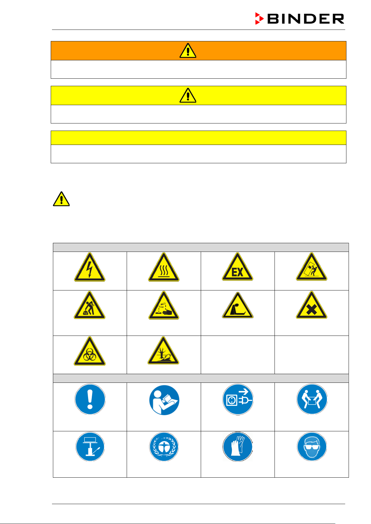
1.2.3 Pictograms
Lifting hazard
Risk of corrosion and / or
Pollution Hazard
Explosive atmosphere
Suffocation hazard
Stability hazard
Harmful substances
Mandatory regulation
Lift with mechanical
BD / BF / ED / FD / FED (E3.1) 07/2017 page 6/99
Read operating
Environment protection Wear protective gloves
Disconnect the power
Lift with several persons
Wear safety goggles

Prohibition signs
water
Pictograms (Warning signs)
Service label
Do NOT touch
Do NOT spray with
Information to be observed in order to ensure optimum function of the product.
1.2.4 Word message panel structure
Type / cause of hazard.
Possible consequences.
∅ Instruction how to avoid the hazard: prohibition.
Instruction how to avoid the hazard: mandatory action.
Observe all other notes and inf ormation not necessarily emphasi zed in the same way, in order to avoid
disruptions that could result in direct or indirect injury or property damage.
1.3 Localization / position of safety labels on the chamber
The following labels are located on the chamber:
Hot surface
• ED, FD, FED: outer chamber door
• BD, BF: on the glass door handle
• On chamber rear next to the exhaust duct
Read operating manual
• UL chamber: outer chamber door
• BD, BF with optional interior socket: below the
interior socket
BD / BF / ED / FD / FED (E3.1) 07/2017 page 7/99
ED, FD, FED
ED-UL, FD-UL, FED-UL
Figure 1: Position of labels on the chamber front (example: ED, FD, FED)
Indications of the type plate (example)
Information
BINDER
Manufacturer: BINDER GmbH
BD 115
Model designation
Incubator
Chamber name: Incubator
Drying and heating oven
Chamber name: Drying and heating oven
Serial No.
000000000000
Serial No of the chamber
Built
2017
Year of construction
100 °C
212 °F
IP protection
20
IP type of protection acc. to EN 60529
Temp. safety device
DIN 12880
Temperature safety device acc. to standard DIN 12880
Class
3.1
Class of temperature safety device
Art. No.
9110-0305
Art. no. of the chamber
Project No.
---
Optional: Special application acc. to project no.
1,30 kW
Nominal power
5,7 A
Nominal current
230 V / 50 Hz
230 V / 60 Hz
1 N ~
Current type
Nominal power: 0,85 kW
Nominal temp.
300 °C
1,30 kW / 5,7 A
572 °F
230 V / 50 Hz
IP protection
20
230 V / 60 Hz
Safety device
DIN 12880
1 N ~
Class
2.0
Art. No.
9010-0305
Project No.
Built
2017
Drying and heating oven
BINDER GmbH
www.binder-world.com
FED 115
E3.1
Serial No. 00000000000000
Nominal temp.
100 °C
0,35 kW / 1,6 A
With option internal socket:
212 °F
230 V / 50 Hz
Nominal power: 0,85 kW
IP protection
20
230 V / 60 Hz
Safety device
DIN 12880
1 N ~
Class
3.1
Art. No.
9110-0325
Project No.
Built
2017
Incubator
BINDER GmbH
www.binder-world.com
BD 115
E3.1
Serial No. 00000000000000
Keep safety labels complete and legible.
Replace safety labels that are no longer legible. Contact BINDER Service for these replacements.
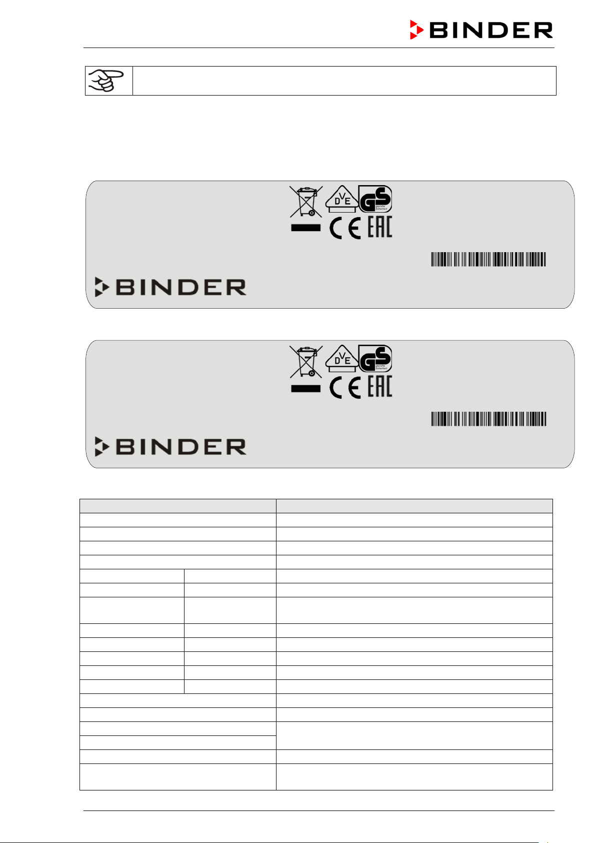
1.4 Type plate
The type plate is located on the left-hand side of the chamber, bottom right-hand.
Im Mittleren Ösch 5
78532 Tuttlingen / Germany
Figure 2: Type plate (example FED 115-230V regular chamber)
Made in Germany
Nominal temperature
Im Mittleren Ösch 5
78532 Tuttlingen / Germany
Made in Germany
Figure 3: Type plate (example BD 115-230V optional chamber)
Nominal temperature
With option internal socket:
BD / BF / ED / FD / FED (E3.1) 07/2017 page 8/99
Nominal voltage ± 10%
at the indicated power frequency
With option internal socket: increased total nominal power
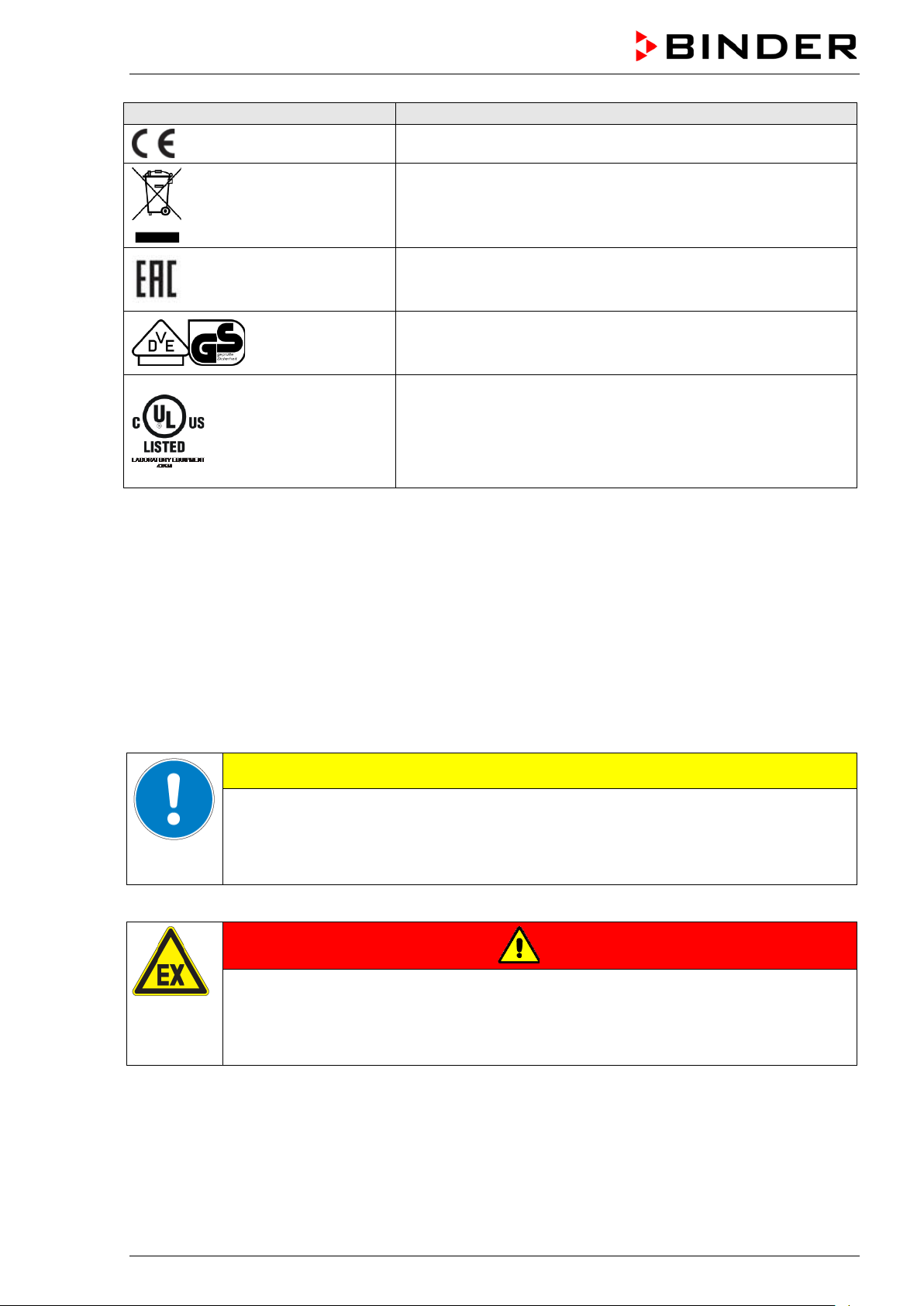
Symbol on the type plate
Information
CE conformity marking
Electrical and electronic equipment manufactured / placed on
the market in the EU after 13 August 2005 and to be disposed of
in a separate collection according to Directive 2012/19/EU on
waste electrical and electronic equipment (WEEE).
The chamber is certified according to Customs Union Technical
Regulation (CU TR) for the Eurasian Economic Union (Russia,
Belarus, Armenia, Kazakhstan Kyrgyzstan).
GS mark of conformity of the “VDE Prüf- und Zertifizierungsinstitut” (Testing and Certification Institute of the Association for
Electrical, Electronic and Information Technologies
The chamber is certified by Underwriters Laboratories Inc.
®
ac-
cording to the following standards:
rd
(UL chambers only)
UL 61010-1, 3
CAN/CSA-C22.2 No. 61010-1, 3
IEC 61010-2-10 :2014, 3
Edition, 2012-05, rev. 2015-07
rd
rd
Edition
Edition, 2012-05, rev. 2015-07
1.5 General safety instructions on installing and operating the chambers
With regard to operating th e chambers and to the ins tallation location, ple ase observe the DGU V guidelines 213-850 on safe working in laboratories (formerly BGI/GUV-I 850-0, BGR/GUV-R 12 0 or ZH 1/119,
issued by the employers’ liability insurance association) (for Germany).
BINDER GmbH is only respons ible for the safety featur es of the chamber provided s killed electricians or
qualified personnel authorized by BIND ER perform all m aintenance and repair, and if components relating to chamber safety are replaced in the event of failure with original spare parts.
To operate the chamber, use only orig inal BINDER accessories or acc essories fr om third-part y suppliers
authorized by BINDER. The user is responsible for any risk caused by using unauthorized accessories.
CAUTION
Danger of overheating.
Damage to the chamber.
∅ Do NOT install the chamber in unventilated recesses.
Ensure sufficient ventilation for dispersal of the heat.
Do not operate the chambers in hazardous locations.
DANGER
BD / BF / ED / FD / FED (E3.1) 07/2017 page 9/99
Explosion hazard.
Danger of death.
∅ Do NOT operate the chamber in potentially explosive areas.
KEEP explosive dust or air-solvent mixtures AWAY from the chamber.
glass doors and glass door han d les (BD, BF), inner chamber, exhaust duct, door
The chambers do not dispose of any measures of explosion protection.
DANGER
Explosion hazard.
Danger of death.
∅ Do NOT introduce any substance into the chamber which is combustible or explosive at
working temperature.
∅ NO explosive dust or air-solvent mixture in the inner chamber.
Any solvent contained in th e charging material m ust not be explosive or inflamm able. I.e., irrespect ive of
the solvent concentrati on in the steam room, NO explos ive mixture with air must f orm. The temperature
inside the chamber mus t lie below the flash point or below th e sublimation po int of the charging m aterial.
Familiarize yourself with the physical and chemical properties of the charging material, as well as the
contained moisture constituent and its behavior with the addition of heat energy.
Familiarize yourself with a ny potential health risks caused b y the charging material, the conta ined moisture constituent or b y reaction products that m ay arise during the temperature pr ocess. Take adequate
measures to exclude such risks prior to putting the chamber into operation.
DANGER
Electrical hazard.
Danger of death.
∅ The chamber must NOT become wet during operation or maintenance.
The chambers were produ ced in accordance with VDE regu lations and were routinel y tested in accordance to VDE 0411-1 (IEC 61010-1).
During and shortly after operation, the temperature of the inner surfaces almost equals the set-point.
CAUTION
The
window (option), and the door gaskets will b ecome hot during operation.
Danger of burning.
∅ Do NOT touch the glass doors, inner surfaces, exhaust duct, door window, access
ports, door gaskets, or the charging material during operation.
BD / BF / ED / FD / FED (E3.1) 07/2017 page 10/99
1.6 Intended use
The chambers are suitable f or ex act tempering of harmless materials and for drying and heat tre at ment of
solid or pulverized c h argi ng material, as well as bu lk mater ia l, usin g th e s up ply of heat. They ca n b e used
to dry e.g. glassware, and for warm storage of liquids in containers.
Because of their precise temperature accuracy the incubators BD and BF are especially useful for incubation of cultures at a standard temperature of 37 °C / 98.6 °F.
A solvent content m ust not be ex plosi ve or flam m able. A m ixture of any componen t of the c harging m aterial with air must NOT be explosi ve. T he oper at ing te mperature must lie below the f lash poin t or below th e
sublimation point of the chargin g material. Any com ponent of th e charging m aterial mus t NOT be able to
release toxic gases.
Other applications are not approved.
The chambers are not classified as medical devices as defined by the Medical D evice Directive
93/42/EEC.
Do NOT use the chamber for drying proces ses when large quantities of vapor would form and result in
condensation.
Due to the special demands of the Medical Device Directive 93/42/EEC, these ovens are not
qualified for sterilization of medical devices as defined by the directive.
Observing the instructions in this operating manual and conducting regular maintenance work
(chap. 13) is part of the intended use.
WARNING: If customer should use a BINDER chamber running in non-supervised continuous operation, we strongly recommend in case of inclusion of irrecoverable specimen or
samples to split such specimen or samples and store them in at least two chambers, if this is
feasible.
The charging material shall not contain any corrosive ingredients that may damage the machine components. Such ingredients include in particular acids and halides. Any corrosive
damage caused by such ingredients is excluded from liability by BINDER GmbH.
The chambers do not dispose of any measures of explosion protection.
DANGER
Explosion or implosion hazard.
Danger of poisoning.
Danger of death.
∅ Do NOT introduce any substance combustible or explosive at working temperature into
the chamber, in particular no energy sources such as batteries or lithium-ion batteries.
∅ NO explosive dust or air-solvent mixture in the inner chamber.
∅ Do NOT introduce any substance which could lead to release of toxic gases.
In case of foreseeable use of the device there is no risk for the user through t he integration of the chamber into systems or by special environmental or operating conditions in th e sense of EN 61010-1:2010.
For this, the intended use of the chamber and all its connections must be observed.
Connect only external devi ces to the chamber interfaces Ether net (regular with FED, optional with BD,
BF, ED, FD) and USB which are compliant with the standards EN 61010-1:2010 or EN 60950-1:2006
mod.
BD / BF / ED / FD / FED (E3.1) 07/2017 page 11/99

(2)
(3)
(1)
2. Chamber description
BINDER incubators BD a nd BF and drying and heating ovens ED, FD an d FED are equipped with an
electronic PID-contro ll er with digit al disp lay.
The incubators BD and BF indicate the temperature with an accuracy of a tenth of a degree.
The drying and heating ovens ED, FD and FED indicate the tem per atur e with an a c cur acy of
one degree.
All chambers are heated electricall y. Incubators BD a nd drying and he ating oven s ED are ventilated n aturally. Incubat ors BF and dr ying and hea ting o vens F D and FED are vent ilated by fan-assisted, forced-air
circulation.
The concept of air conduction guarantees high level of spatial and time-based temperature precision,
thanks to the direct and distr ibuted air circ ulation into the inter ior. W ith BF, F D an d FED , the f an su pports
exact attainment and maintenance of the desired temperature accur ac y.
The chambers are regularly equipped with an overtemperature safety device class 1 acc. to
DIN12880:2007 and with a n overtemperature safety controller (overtemperature temperatur e safety device class 2 or class 3.1 acc. to DIN12880:2007), see chap. 7).
The inner chamber and the inside of the d oors are made of stainless steel V2A (G erman material no.
1.4301, US equivalent AIS I 304 and m aterial no. 1.4016, US equiva lent AISI 430). Dr ying and heating
ovens ED, FD and FE D: When operatin g the chambers at tem peratures above 150 °C / 302 °F, the impact of the ox ygen in t he ai r may cause discoloratio n o f the metallic surfaces (yellowish-brown or blue) b y
natural oxidation processes. These colorations are harmless and will in no way impair the function or
quality of the chamber. The housing is RAL 703 5 powder-coated. All corners and ed ges are also completely coated.
All chamber functions are eas y and comfortable to use thank s to their cle ar arrangem ent. Major feat ures
are easy cleaning of all chamber parts and avoidance of undesired contamination.
The chambers ar e regularly (FED) or optionall y equipped with an Ethernet interf ace for computer communication, e.g. via the com munication software APT -COM™ 3 DataControlSystem (option, chap. 12.1)
and with a USB interface to read out the measured values in real time.
Temperature ranges see technical data (chap. 16.4 - 16.8).
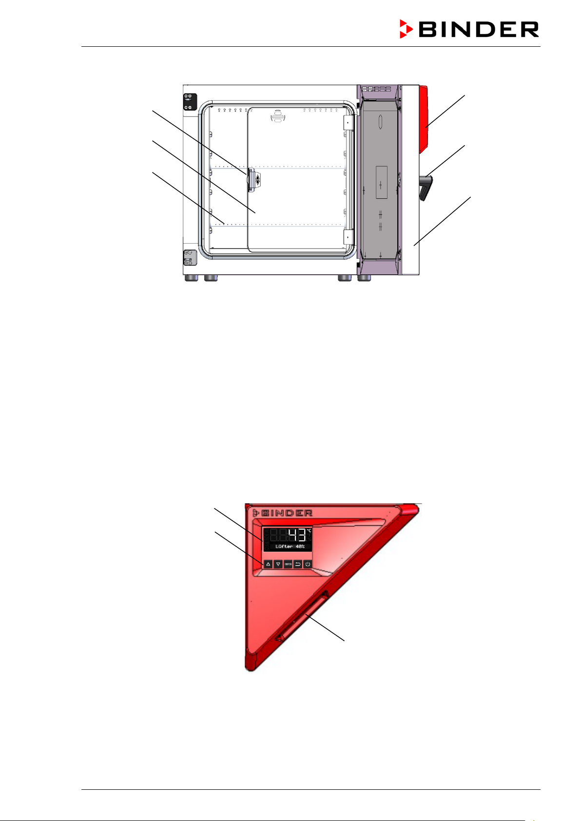
2.1 Chamber overview
Figure 4: Overview, closed chamber
BD / BF / ED / FD / FED (E3.1) 07/2017 page 12/99
(4)
(3)
(6)
(5)
(1)
(2)
(9)
(8)
(7)
Figure 5: Overview, open chamber with glass door (BD, BF)
(1) Triangular instrument panel with controller R4 and USB interface
(2) Door handle
(3) Outer door
(4) Glass door handle (BD and BF)
(5) Glass door (BD and BF)
(6) Rack
2.2 Triangular instrument panel
Figure 6: Triangular instrument panel
(7) Controller display
(8) Functional controller buttons
(9) USB interface
BD / BF / ED / FD / FED (E3.1) 07/2017 page 13/99
3. Completeness of delivery, transportation, storage, and installa-
tion
3.1 Unpacking, and checking equipment and completeness of delivery
After unpacking, p lease check the chamber and its optional accessories, if any, based on the delivery
receipt for completenes s and for transportation damage. Inf orm the carrier immediately if trans portation
damage has occurred.
The final tests of the m anufacturer m ay have caused trac es of the rack s on the inner surfac es. This has
no impact on the function and performance of the chamber.
Please remove any transportation pr otection devices and adhes ives in/on the chamber and on the doors
and take out the operating manuals and accessory equipment.
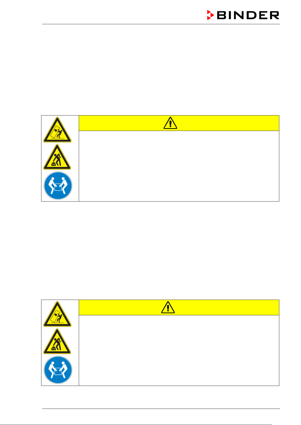
CAUTION
Sliding or tilting of the chamber.
Damage to the chamber.
Risk of injury by lifting heavy loads.
∅ Do NOT lift or transport the chamber using the door handle or the door.
Lift the chamber size 56 and 115 from the pallet at its four lower corners with the aid
of 2 people, chamber size 260 with the aid of 4 people.
If you need to return the chamber, pleas e use the original packing and o bserve the guidelines for safe
lifting and transportation (chap. 3.2).
For disposal of the transport packing, see chap. 14.1.
Note on second-hand chambers (Ex-Demo-Units):
Second-hand chambers are chambers that have been used f or a short time for tests or exhibitions. T hey
are thoroughly tested b efor e resale . BIND ER ens ures that the c ham ber is technic all y sound and will work
flawlessly.
Second-hand chambers are marked with a sticker on the chamber door. Please remove the stick er bef ore
commissioning the chamber.
3.2 Guidelines for safe lifting and transportation
After operation please observe the guidelines for temporarily decommissioning the chamber (chap. 14.2).
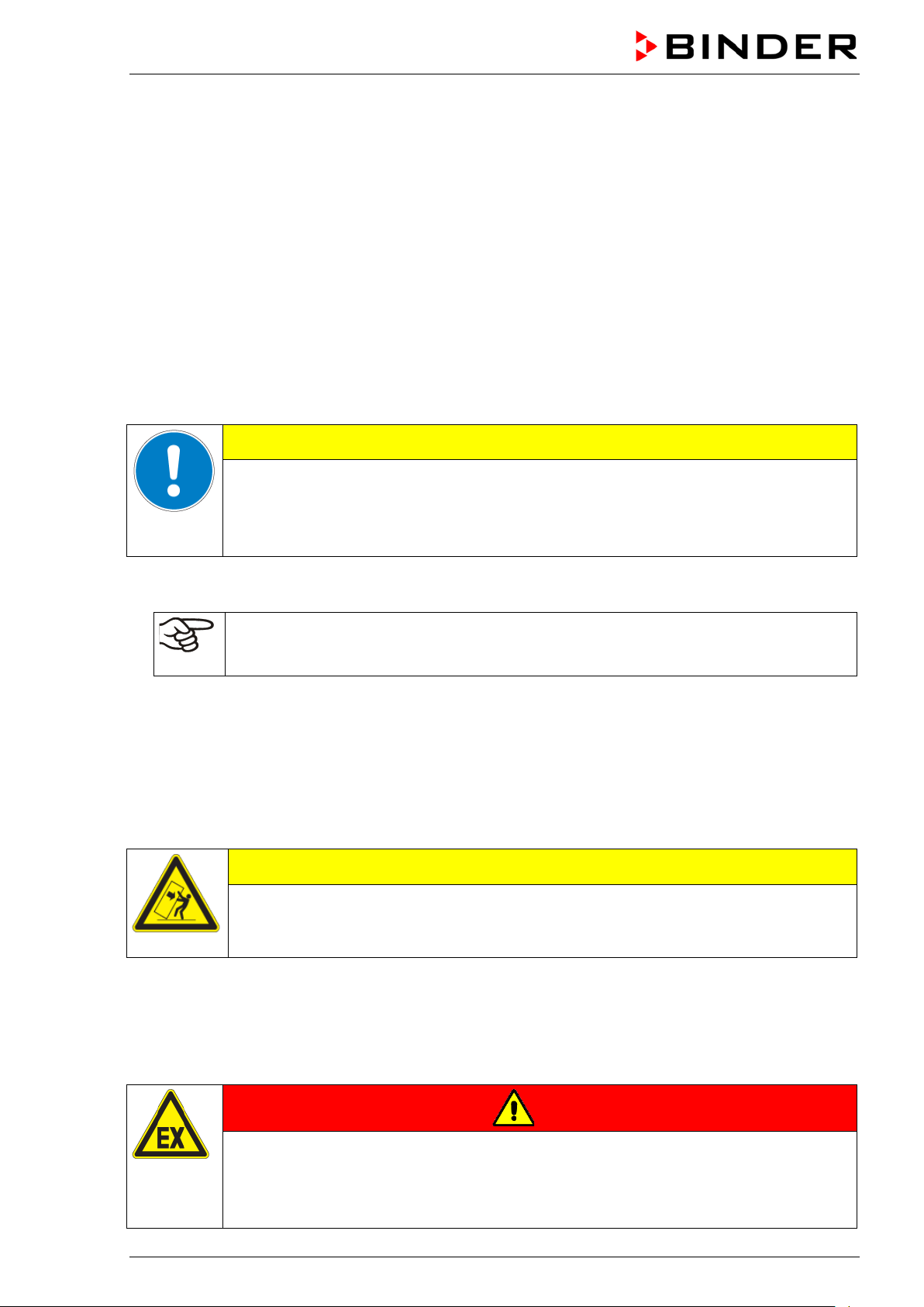
CAUTION
Sliding or tilting of the chamber.
Damage to the chamber.
Risk of injury by lifting heavy loads.
Transport the chamber only in its original packaging.
Secure the chamber with transport straps for transport.
∅ Do NOT lift or transport the chamber using the door handle or the door.
Lift chamber size 56 and 115 at its four lower corners with the aid of 2 people,
chamber size 260 with the aid of 4 people, and place it on a transport pallet with
wheels. Push the pallet to the desired site and then lift the chamber from the pallet at
its four lower corners.
• Permissible ambient temperature range during transport: -10 °C to +60 °C / 14 °F to 140 °F.
You can order transport packing and pallets for transportation purposes from BINDER Service.
BD / BF / ED / FD / FED (E3.1) 07/2017 page 14/99
3.3 Storage
Intermediate storage of the chamber is possible in a closed and dry room . Observe the guidelines for
temporary decommissioning (chap. 14.2).
• Permissible ambient temperature range during storage: -10 °C to +60 °C / 14 °F to 140 °F.
• Permissible ambient humidity: max. 70 % r.H., non-condensing
When after storage in a co ld location you transfer the chamber to its warm er installation site, condens ation may form. Befor e start-up, wait at least one hour u ntil the chamber has attai ned am bient tem per ature
and is completely dry.
3.4 Location of installation and ambient conditions
Set up the chamber on an eve n and non-flammable sur face, free from vibration and i n a well-ventilated,
dry location and align it using a spirit level. The site of installation must be capable of supporting the
chamber’s weight (see technical data, chap. 16.4 to 16.7). The chambers are designed for setting up
inside a building (indoor use).
CAUTION
Danger of overheating.
Damage to the chamber.
∅ Do NOT set up chambers in non-ventilated recesses.
Ensure sufficient ventilation for dispersal of the heat.
• Permiss ible ambient temper ature range during oper ation: +18 °C up to +40 ° C / 64.4 °F to 104 °F. At
elevated ambient temperature values, fluctuations in temperature can occur.
The ambient temperature should not be substantially higher than the indicated ambient
temperature of +25 °C / 77 °F to which the specified technical data relate. For other ambient conditions, deviations from the indicated data are possible.
• Permissible ambient humidity: 70 % r.H. max., non-condensing.
• Installation height: max. 2000 m / 6562 ft. above sea level.
When placing several chambers of the sam e size side b y side, m aintain a m inim um distance of 250 mm /
9.84 in between each chamber. W all distances: rear 160 mm / 6.30 in, sides 100 mm / 3.94 in. Spacing
above the chamber of at least 100 mm / 3.94 in must also be accounted for.
Two devices up to si ze 115 can be stac ked on t op of each ot her. For t his purpos e place r ubber pads u nder all four feet of the upper chamber to prevent the device from slipping.
CAUTION
Sliding or tilting of the upper chamber.
Damage to the chambers.
When stacking, place rubber pads under all four feet of the upper chamber.
To completely separat e the chamber from the power supp ly, you mus t disconnect the power plug. Install
the chamber in a way that the po wer p lug is e asil y acc essible and can b e eas il y pulled in cas e of danger .
Do not conduct the power cable above the exhaust duct.
For the user there is no risk of temporary overvoltages in the sense of EN 61010-1:2010.
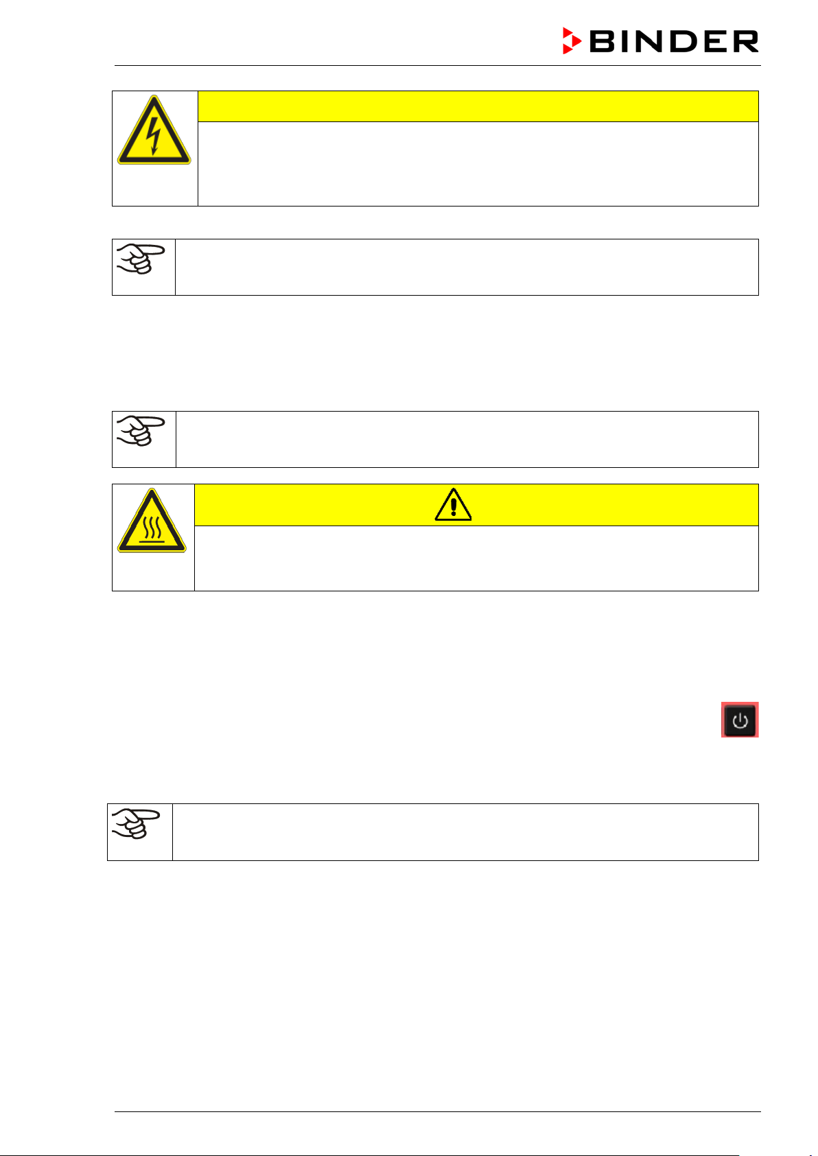
Do not install or operate the chamber in potentially explosive areas.
DANGER
Explosion hazard.
Danger of death.
∅ Do NOT operate the chamber in potentially explosive areas.
KEEP explosive dust or air-solvent mixtures AWAY from the vicinity of the chamber.
BD / BF / ED / FD / FED (E3.1) 07/2017 page 15/99

4. Installation
4.1 Mounting the tilt protection holders (chambers with window)
For chambers equipped with the option „door with window“ it is recommended to insta ll the supplied tilt
protection.
Scope of delivery of tilt protectio n kit (Art.no. 8009-0870):
• 2 screws
• 2 tilt protection holders
Preparing the tilt protection holders
• Depending on the desired wall distance, you can bend the tilt protection holders acc ording ly.
Figure 7: Variable length of the tilt protection holder depending on the bend
Installation on the chamber
• Plug the two tilt protec tion hol ders eac h with the tab on the provided spot on the edge of the rear pan-
el. The screw holes in the rear wall and in the tilt protection holders must align.
• Fix the tilt protection holders each with one of the supplied screws on the chamber rear wall.
Wall mounting
• Then fix both tilt protection holders on the wall, each with 2 screws Ø 6mm suitable for the wall (B)
BD / BF / ED / FD / FED (E3.1) 07/2017 page 16/99

FED056-230V
ED115-230V
FED115-230V
FED260-230V
ED056UL-120V
FED056UL-120V
FD115UL-120V
ED260UL-240V
FED260UL-240V
4.2 Electrical connectio n
The chambers are supplied ready for connection and come with an IEC connector plug.
Model
BD056-230V
BF056-230V
ED056-230V
FD056-230V
BD115-230V
BF115-230V
FD115-230V
BD260-230V
BF260-230V
ED260-230V
FD260-230V
BD056UL-120V
BF056UL-120V
FD056UL-120V
Power plug of the
power cable
Shockproof plug
Shockproof plug
Shockproof plug
Shockproof plug
Shockproof plug
Shockproof plug
NEMA 5-15P
NEMA 5-15P
Nominal voltage +/- 10% at the
indicated power frequency
230 V at 50 Hz
230 V at 60 Hz
230 V at 50 Hz
230 V at 60 Hz
230 V at 50 Hz
230 V at 60 Hz
230 V at 50 Hz
230 V at 60 Hz
230 V at 50 Hz
230 V at 60 Hz
230 V at 50 Hz
230 V at 60 Hz
115 V at 50 Hz
115 V at 60 Hz
115 V at 50 Hz
115 V at 60 Hz
Current
type
Chamber
fuse
1N~ 6,3 A
1N~ 6,3 A
1N~ 6,3 A
1N~ 6,3 A
1N~ 8,0 A
1N~ 12,5 A
1N~ 12,5 A
1N~ 12,5 A
BD115UL-120V
BF115UL-120V
ED115UL-120V
FD115UL-120V
BD260UL-120V
BF260UL-120V
FD260UL-240V
NEMA 5-15P
NEMA 5-15P
NEMA 5-15P
NEMA 6-20P
115 V at 50 Hz
115 V at 60 Hz
115 V at 50 Hz
115 V at 60 Hz
115 V at 50 Hz
115 V at 60 Hz
240 V at 50 Hz
240 V at 60 Hz
1N~ 12,5 A
1N~ 12,5 A
1N~ 12,5 A
2~ ---
• The dom estic socket must also prov ide a protective conduct or. Make sure that the connection of the
protective conductor of the domestic installations to the chamber’s protective conductor meets the
latest technology. The protective conductors of the socket and plug must be compatible!
• Prior to connection and start-up, check the power su ppl y voltag e. Com pare t he values to the s pecif ied
data located on the chamber’s type plate (left-hand side of the chamber, chap. 1.4).
• When connecting, please observe the regulations specified by the local electricity supply company
and as well as the VD E directives (for Germ any). We recommend the us e of a residua l current circ uit
breaker.
• Only use original connection cables from BINDER.
• Pollution degree (acc. to IEC 61010-1): 2
• Over-voltage category (acc. to IEC 61010-1): II
BD / BF / ED / FD / FED (E3.1) 07/2017 page 17/99
CAUTION
Danger of incorrect power supply voltage.
Damage to the equipment.
Check the power supply voltage before connection and start-up.
Compare the power supply voltage with the data indicated on the type plate.
See also electrical data (chap. 16.4 to 16.7).
To completely separate the chamber from the power supply, you must disconnect the power
plug. Install the chamber in a way that the power plug is easily accessible and can be easily
pulled in case of danger.
4.3 Connection to a suction plant (optional)
When directly connectin g a suction plant the spatial temper ature exactitude, the heating-up a nd the recovering times and the m aximum temperature will be negativ ely influenced. So no suction p lant sho ul d be
directly connected to the exhaust duct.
Active suction from the chamber must only be effected together with extraneous air. Perforate
the connecting piece to the suction device or place an exhaust funnel at some distance to the
exhaust duct.
CAUTION
The exhaust duct will become hot during ope ration.
Danger of burning.
∅ Do NOT touch the exhaust duct during operation.
5. Start up
Insert the plug into a suitable socket (chap. 4.2).
If there is no other indicati on on the controller than the s tandby symbol, press th e standby button
until the display lights up.
The controller no w shows normal disp lay (chap. 6.2). If a timer function was active pri or to turn ing off the
chamber, it is shown in the controller display.
Warming chambers may release odors in the first few days after commissioning. This is not a
quality defect. To reduce odors quickly we recommend heating up the chamber to its nominal
temperature for one day and in a well-vent ilat ed loc at io n.
5.1 Behavior when opening the door
BD, ED: Depending on the temperature, heating performance may be adapted when opening the door.
BF, FD, FED: When opening the door, heating and fan turn off as long as the door remains open.
BD / BF / ED / FD / FED (E3.1) 07/2017 page 18/99
6. Overview and general settings on the R4 controller
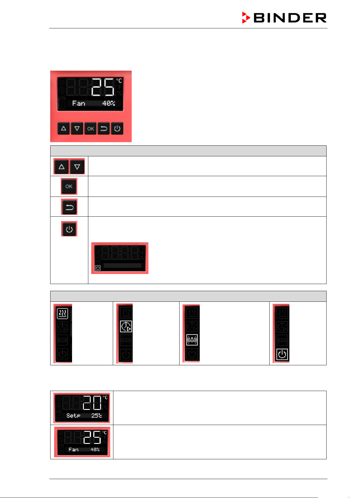
6.1 Controller overview
Buttons on the controller
The arrow buttons serve to navigate and to enter the values
The OK button serves to select the parameters and to confirm the entered values
The Back button serves to reach the preceding level
If the Standby button is pressed down for approx. 3 seconds, the display changes to
standby mode. To activate the display, press down the standby button again for approx.
3 seconds
Display in standby mode with standby symbol
Status symbols on the controller display
Heating
active
Timer
operation
Overtemperature
alarm of the safety
controller
Standby
mode
6.2 Normal display
Normal display with chambers without fan (BD, ED)
or with fixed fan speed (FD)
Normal display with chambers with adjustable fan speed (BF, FED)
BD / BF / ED / FD / FED (E3.1) 07/2017 page 19/99
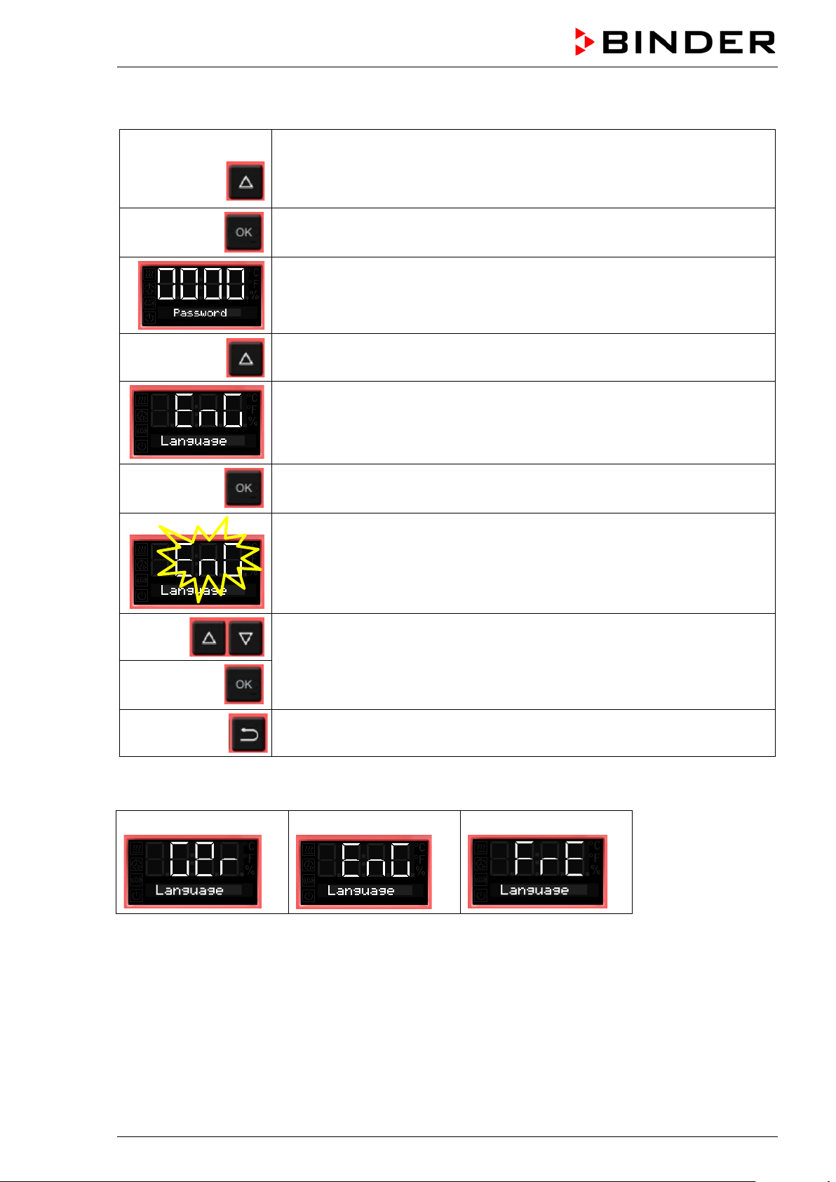
6.3 Setting the menu language
From Normal display
without fan 5x
with fan 6x
4 x
with the arrow-up button to the user menu
Confirm with OK.
Enter the password (factory setting: 00 00)
and confirm each entry with OK.
with the arrow-up button to the language setting menu.
The current menu language is shown.
Press OK to select the menu language.
The setting flashes.
Select the setting with the arrow buttons
and confirm with OK.
2x
There are the following options:
German:
Back to Normal display.
English:
French:
BD / BF / ED / FD / FED (E3.1) 07/2017 page 20/99

6.4 Setting date and time
From Normal display
without fan 5x
with fan 6x
with the arrow-up button to the user menu
Confirm with OK.
Enter the password (factory setting: 00 00)
and confirm each entry with OK.
The current date is shown.
Press OK to set the year.
The setting flashes.
Enter the year with the arro w buttons (any setting)
and confirm with OK.
Press OK to set the month.
The setting flashes.
Enter the month with arr o w buttons (1 to 12)
and confirm with OK.
Without the optional real time clock, these settings must be repeated when the power supply is
interrupted..
BD / BF / ED / FD / FED (E3.1) 07/2017 page 21/99

Press OK to set the day.
The setting flashes.
Enter the day with arrow buttons (1 to 31)
and confirm with OK.
Press OK to set the hour.
The setting flashes.
Enter the hour with arrow buttons (0 to 23)
and confirm with OK.
Press OK to set the minute.
The setting flashes.
Enter the minute with arrow buttons (0 to 59)
and confirm with OK.
2x
Back to Normal display.
BD / BF / ED / FD / FED (E3.1) 07/2017 page 22/99
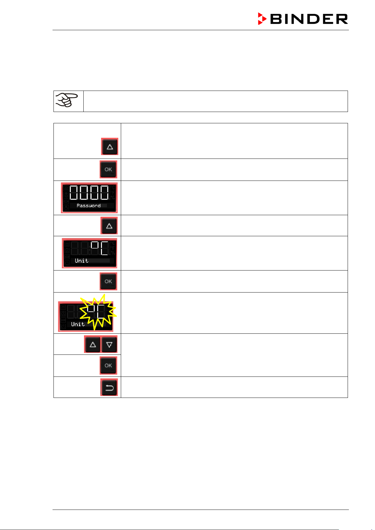
6.5 Selecting the temperature unit
You can chose between degrees Celsius °C and degrees Fahrenheit °F.
If the unit is changed, the temperature set-point and limits are converted accordingly.
Also when specifying the ramp function (see chap. 9) this setting is accordingly taken as the basis.
C = degrees Celsius
F= degrees Fahrenheit
without fan 5x
with fan 6x
0 °C = 31°F
100 °C = 212°F
From Normal display
with the arrow-up button to the user menu
Confirm with OK.
Enter the password (factory setting: 00 00)
and confirm each entry with OK.
With the arrow-up button to the temperature unit selection menu.
The current temperature unit is shown.
Conversion:
[Value in °F] = [Value in °C] ∗ 1.8 + 32
Press OK to select the temperature unit.
The setting flashes.
Select the setting with arrow buttons
and confirm with OK.
2x
Back to Normal display.
BD / BF / ED / FD / FED (E3.1) 07/2017 page 23/99
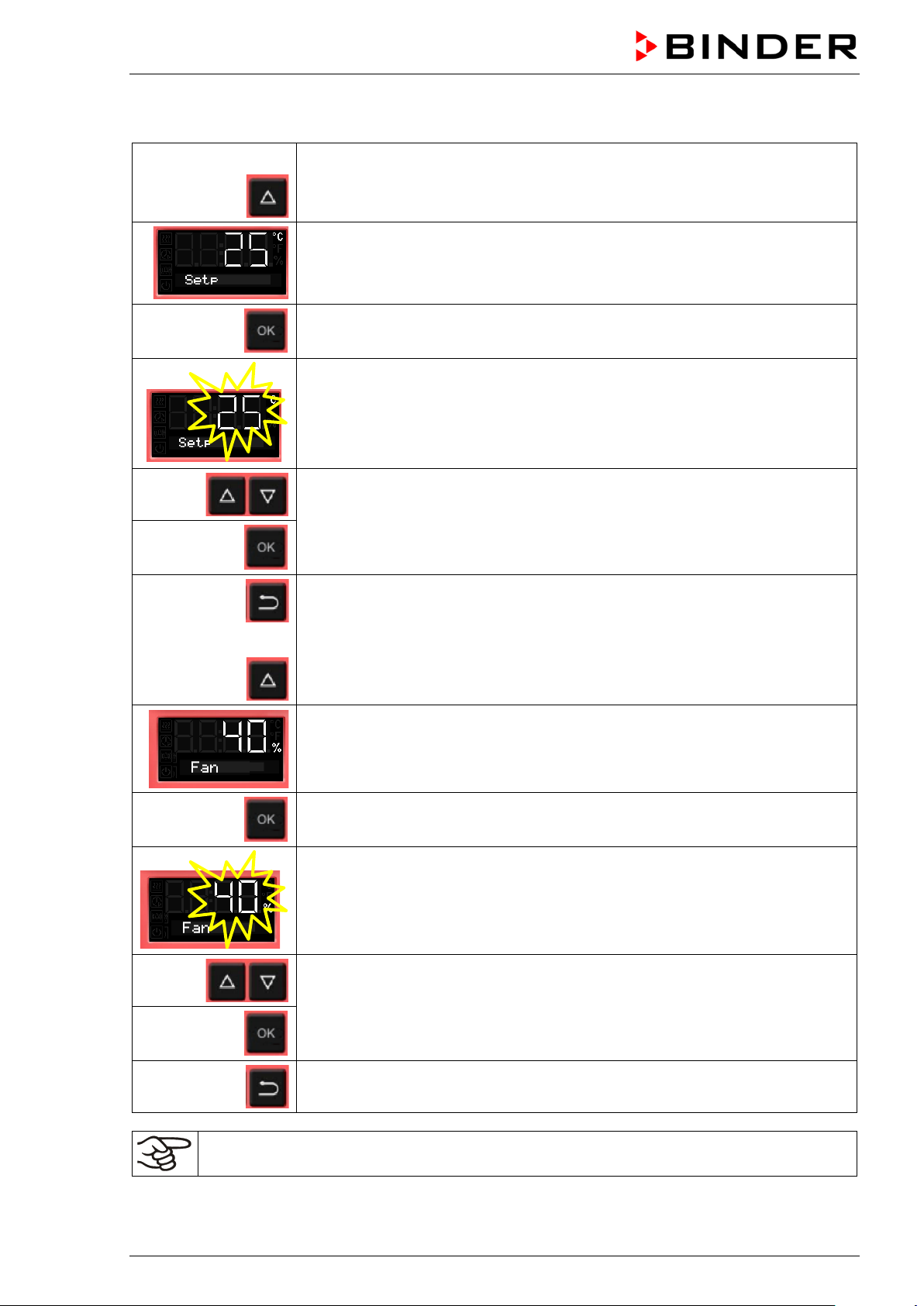
6.6 Set-point entry for temperature and fan speed
From Normal display
with the arrow-up button to the Set-point entry menu.
The current temperature set-point is displayed.
Press OK to enter the temperature set-point.
The temperature set-point flashes.
Enter the temperature set-po int wit h arr o w buttons with an accuracy of a tenth
of a degree (BD, BF) or of one degree (ED, FD, FED)
or
and confirm with OK.
Back to Normal display.
with chambers with adjustable fan speed (BF, FED):
go on to enter the fan speed.
The fan speed set-point is displayed.
Press OK to enter the fan speed
The fan speed set-point flashes
Adjust the fan speed in steps of 10 % with arrow buttons
and confirm with OK.
Back to Normal display.
Check and/or adjust the safety controller following any changes of the set-point (chap. 7).
BD / BF / ED / FD / FED (E3.1) 07/2017 page 24/99
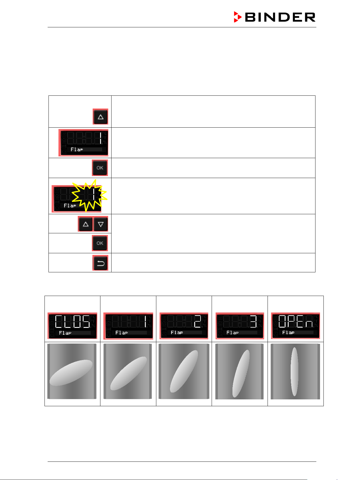
6.7 Adjusting the air flap position
Opening the air flap in the exhaust duct serves to adjust the air change.
The position of the air f lap in the exhaust duct serv es to adjust the fresh air entry. With the open th e air
flap, fresh air can enter through the fresh air tube. For chambers with fan, fan operation will increase
fresh air entry.
If the air flap is completely open, the spatial temperature accuracy can be negatively influenced.
From Normal display
without fan 2x
with fan 3x
with the arrow-up button to the Adjusting the air flap position menu.
The current air flap position is shown.
Press OK to select the air flap position.
The setting flashes.
Select the position with arrow buttons
and confirm with OK.
Back to Normal display.
There are the following options:
Air flap
closed
The setting can be done in steps of 15°.
Air flap slightly
opened
Air flap half opened
Air flap almost
open
Air flap open
BD / BF / ED / FD / FED (E3.1) 07/2017 page 25/99

6.8 Changing the passwords for user level and general controller functions
In this menu you can change the passwords for access to the user menu and to all controller functions.
You can set two passworts for different access levels:
L1 (level 1): The password enables access control to the user level
L2 (level 2): The password enables access control to all controller functions
Factory setting for both passwords is 00 00 (no password assigned).
As soon as a password has been assigned, ac cess to the res pective functions is blocked and onl y avail-
able after enering the correct password.
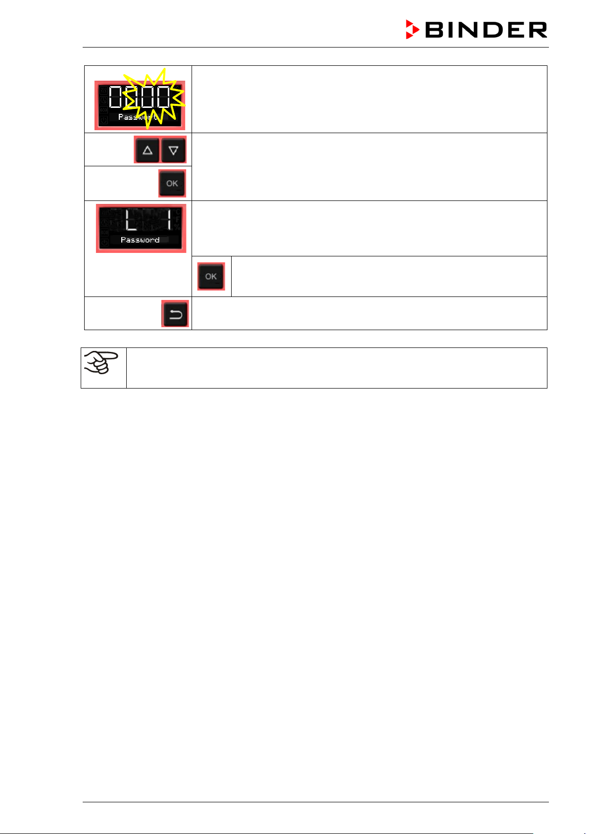
From Normal display
without fan 5x
with fan 6x
2 x
with the arrow-up button to the user menu
Confirm with OK.
Enter the password (factory setting: 00 00)
and confirm each entry with OK.
With the arrow-up button to the password setting menu.
Password L1 for access to the user level.
Confirm with OK.
The current password level L1
is shown. The setting flashes.
You can change beween L1
and L2 with arrow buttons.
Select the setting with arrow
buttons (if desired)
and confirm with OK.
The current password for the selected password level is shown. The left two
digits are flashing.
Enter the desired numbers with arrow buttons,
confirm with OK and go on.
BD / BF / ED / FD / FED (E3.1) 07/2017 page 26/99
The right two digits of the password are flashing.
Enter the desired numbers with arrow buttons
and confirm with OK.
The modified password (L1 or L2 depending on the selection) is shown
(example: L1).
If you want to change beween L1 and L2, confirm with OK. Thereafter you can change to the other password level and also modify the
password.
2x
Keep in mind any modification of the password. There is no access to the user menu without
the correct password L1. Without the correct password L2 access control to all controller functions is blocked.
Back to Normal display.
BD / BF / ED / FD / FED (E3.1) 07/2017 page 27/99
7. Overtemperature protection
7.1 Overtemperature protective device (class 1)
The chambers are regularl y equipped with an overtemperature protect ive device (safety device class 1
acc. to DIN 12880:2007). I t serves to protect t he chamber, its enviro nment and the contents a gainst exceeding the maxim um permissible temperature. When a defined tem per ature is reac hed, whic h is approx.
by 20 °C to 30 °C above the c hamber’s nominal tem peratur e, t he ov er temperature protective d evic e tur ns
off the heating.
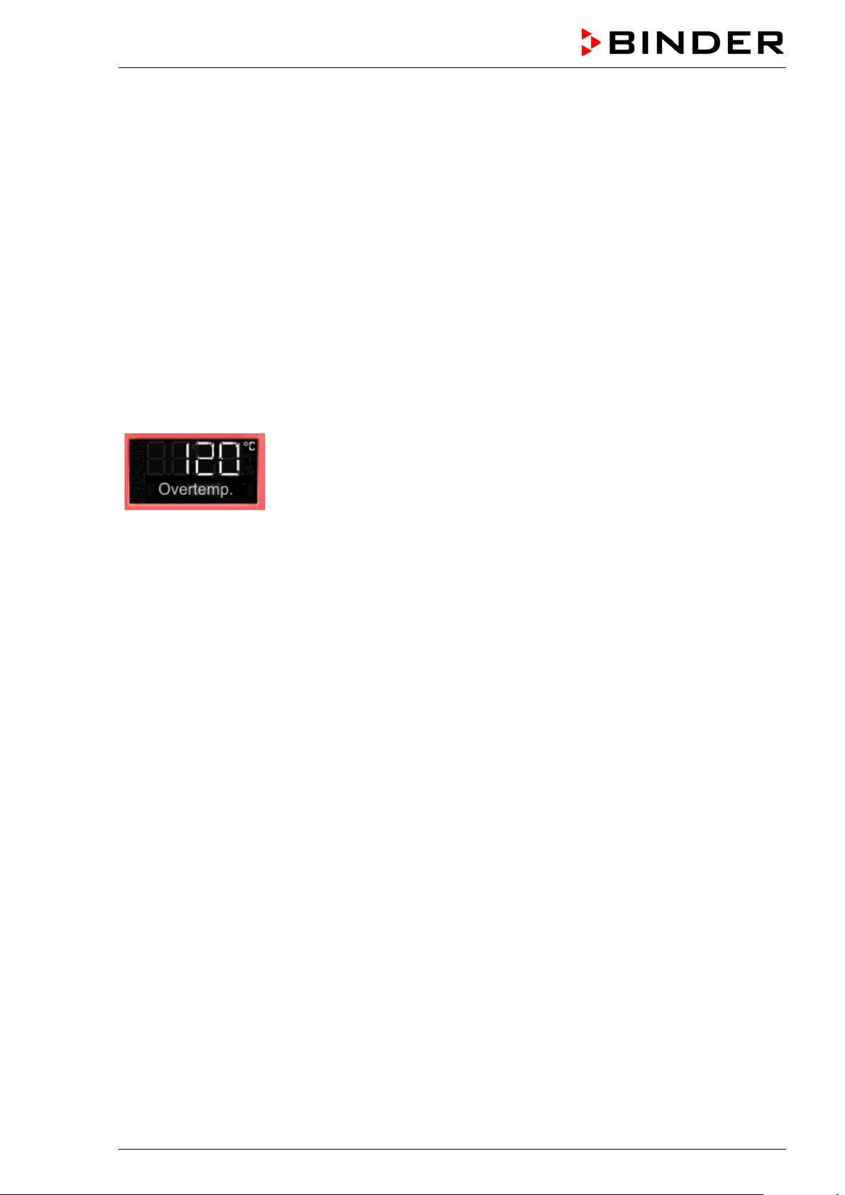
Cut-off temperature values:
BD, BF: 120 °C
ED 260: 320 °C
ED 56, ED 115, FD 56, FED 56: 330 °C
FD 115, FD 260, FED 115, FED 260: 350 °C
The message “Overtemperature” is displayed on the controller.
If the overtemperature protective device class 1 has turned off the heating, proceed as follows:
• Disconnect the chamber from the power supply for at least 10 seconds (pull the power plug).
• If appropriate, have an expert examine and rectify the cause of the fault.
• Let the chamber cool down
• Restart the chamber.
As soon as the inner cham ber temperature after restart is below the defined cut-off temperature of the
overtemperature protective device class 1, the alarm message is deleted automatically.
Reset temperature values:
BD, BF: 90 °C
ED 260: 220 °C
ED 56, ED 115, FD 56, FED 56: 230 °C
FD 115, FD 260, FED 115, FED 260: 250 °C
BD / BF / ED / FD / FED (E3.1) 07/2017 page 28/99

7.2 Safety controller
The chambers ar e regularly equipped with an adjustable electronic saf ety controller. It serves to protect
the chamber, its en vironm ent and t he co ntents against exceeding the m ax imum perm issible tem perature.
Please observe the DGUV gui del in es 213-850 on safe working in lab orator i es ( f ormerly BGI/GUV-I 850-0,
BGR/GUV-R 120 or ZH 1/119, issued by the employers’ liability insurance association) (for Germany).
Depending on the cham ber type the safety controller acts as an over temperature s afety device class 2
(“temperature limiter”) or class 3.1 (“temperature protection”) acc. to DIN 12880:2007.
Check the setting regularly and adjust it following any changes of the set-point.
• Safety controller class 2 (“temperature limiter”) with ED, FD and FED
The safety controller class 2 lim its the tem perature ins ide the cham ber to the ent ered safet y controller
set-point. In the event of a fault (if this maxim um temperature is exceede d) the safety contro ller completely turns of f the heating unti l manual reset. This s tatus is reported visually by an alarm message
and, in case of the option aud ible alarm with activated buzzer (chap. 7.6) additionally by the buzzer
sounding.
If the safety controller class 2 has turned off the heating, we recommend proceeding as follows:
• Disconnect the chamber from the power supply.
• Have an expert examine and rectify the cause of the fault.
• Restart the chamber
• Reset the alarm message
• Safety contro ller class 3.1 (“temperature protection”) with BD and BF
The safety controller class 3.1 limits the tem perature i nside the cham ber to the enter ed safet y controller set-point. In the event of a fault (if this maxim um tem per ature is exc eeded), it takes over the c ontro l
to this value. T his status is reported v isually by an alarm message and, in case of the option audible
alarm with activated buzzer (chap. 7.6) additionally by the buzzer sounding.
The safety controller k eeps control of the cham ber until the chamber temperatur e cools down below
the safety controller set-point value.
If the safety controller class 3.1 has taken over control, we recommend proceeding as follows:
• Disconnect the chamber from the power supply.
• Have an expert examine and rectify the cause of the fault.
• Restart the chamber
• Reset the alarm message
Function check:
Check the safety contro ller at ap propriat e inter vals f or i ts func tionalit y. It is r ecom m ended that the aut horized operating personnel should perform such a check, e.g., before starting a longer work procedure.
BD / BF / ED / FD / FED (E3.1) 07/2017 page 29/99

7.3 Setting the safety controller set-point
A limit temp erature is entered as the safety controller set-point , i.e. the absol ute maximum permitted
temperature value.
Example: Temperature set-point 45 °C, safety controller set-point 50 °C.
Regularly check the safety controller setting relating to the entered temperature set-point
Set the safety controller set-point by approx. 2 °C to 5 °C above the desired temperature set-
point.
From Normal display
without fan 4x
with fan 5x
with the arrow-up button to the Safety controller set-point setting menu.
The current safety controller set-point is shown
(class 2 “temperature limiter” or class 3.1 “temperature protection” depending
on the chamber type).
Press OK to enter the safety controller set-point.
The safety controller set-point flashes.
Enter the safety controller set-point with arrow buttons:
10 °C up to 100 °C (with an accuracy of a tenth of a degree) with BD, BF
10 °C up to 300 °C (with an accuracy of one degree) with ED, FD, FED
and confirm with OK.
Back to Normal display.
BD / BF / ED / FD / FED (E3.1) 07/2017 page 30/99
Loading...