


C 150
Issue 12/2012 Art. No. 7001-0172
Operating Manual
APT.line™ C 150 (E2)
CO
2
Incubators
with FPI-sensor system
and display controller RP1
Model
Art. No.
Door hinges
Voltage
C150
9040-0078, 9140-0078
right
230 V
C150
9040-0081, 9140-0081
left
230 V
C150-UL
9040-0079, 9140-0079
right
115 V
C150-UL
9040-0082, 9140-0082
left
115 V
C150
9040-0080, 9140-0080
right
100 V
C150
9040-0083, 9140-0083
left
100 V
BINDER GmbH
Address Post office box 102
D-78502 Tuttlingen
Tel. +49 7462 2005 0
Fax +49 7462 2005 100
Internet http://www.binder-world.com
E-mail info@binder-world.com
Service Hotline +49 7462 2005 555
Service Fax +49 7462 2005 93 555
Service E-Mail service@binder-world.com
Service Hotline USA +1 866 885 9794 or +1 631 224 4340 x3
Service Hotline Asia Pacific +852 39070500 or +852 39070503
Service Hotline Russia and CIS +7 495 98815 17

C 150 (E2) 12/2012 page 2/90
EC – declaration of conformity
EG – KONFORMITÄTSERKLÄRUNG
EC - DECLARATION OF CONFORMITY
CE - DECLARATION DE CONFORMITE
Anbieter / Supplier / Fournisseur:
BINDER GmbH
Anschrift / Address / Adresse:
Im Mittleren Ösch 5, D-78532 Tuttlingen
Produkt / Product / Produit:
CO
2
-Inkubator
CO
2
Incubator
Incubateur à CO
2
Typenbezeichnung / Type / Type:
C 150
Die oben beschriebenen Produkte sind konform mit folgenden EG-Richtlinien:
The products described above are in conformity with the following EC guidelines:
Les produits décrits ci-dessus sont conformes aux directives CE suivantes:
Niederspannungsrichtlinie
2006/95/EG
Low voltage directive
2006/95/EC
Directive basse tension
2006/95/CE
Richtlinie 2006/95/EG des Europäischen Parlaments und des Rates vom 12.
Dezember 2006 zur Angleichung der Rechtsvorschriften der Mitgliedstaaten
betreffend elektrische Betriebsmittel zur Verwendung innerhalb bestimmter
Spannungsgrenzen
Council Directive 2006/95/EC of 12 December 2006 on the harmonization of
the laws of Member States relating to electrical equipment designed for use
within certain voltage limits
Directive 2006/95/CE du Parlement Européen et du Conseil du 12 décembre
2006 concernant le rapprochement des législations des États membres rela-
tives au matériel électrique destiné à être employé dans certaines limites de
tension
EMV-Richtlinie
2004/108/EG
EMC Directive
2004/108/EC
Directive CEM
2004/108/CE
Richtlinie 2004/108/EG des Europäischen Parlaments und des Rates vom
15. Dezember 2004 zur Angleichung der Rechtsvorschriften der Mitglied-
staaten über die elektromagnetische Verträglichkeit und zur Aufhebung der
Richtlinie 89/336/EWG.
Directive 2004/108/EC of the European Parliament and of the Council of 15
December 2004 on the approximation of the laws of the Member States
relating to electromagnetic compatibility and repealing Directive 98/336/EEC.
Directive 2004/108/CE du Parlement Européen et du Conseil du 15 dé-
cembre 2004 relative au rapprochement des législations des États membres
concernant la compatibilité électromagnétique et abrogeant le directive
98/336/CEE.
Die oben beschriebenen Produkte tragen entsprechend die Kennzeichnung CE.
The products described above, corresponding to this, bear the CE-mark.
Les produits décrits ci-dessus, en correspondance, portent l’indication CE.
1 / 3

C 150 (E2) 12/2012 page 3/90
Die oben beschriebenen Produkte sind konform mit folgenden harmonisierten Normen:
The products described above are in conformity with the following harmonized standards:
Les produits décrits ci-dessus sont conformes aux normes harmonisées suivantes:
Sicherheit / safety / sécurité:
EN 61010-1:2010
Sicherheitsbestimmungen für elektrische Mess-, Steuer-, Regel- und
Laborgeräte – Teil 1: Allgemeine Anforderungen (DIN EN 61010-
1:2011, VDE 411-1:2011)
Safety requirements for electrical equipment for measurement, control,
and laboratory use – Part 1: General requirements (IEC 61010-1:2010,
BS EN 61010-1:2010)
Règles de sécurité pour appareils électriques de mesurage, de régula-
tion et de laboratoire – Partie 1: Prescriptions générales (CEI 61010-
1:2010, NF EN 61010:2011)
EN 61010-2-010:2003
Sicherheitsbestimmungen für elektrische Meß-, Steuer-, Regel- und
Laborgeräte – Teil 2-010: Besondere Anforderungen an Laborgeräte für
das Erhitzen von Stoffen (DIN EN 61010-2-010:2004)
Safety requirements for electrical equipment for measurement, control,
and laboratory use – Part 2-010: Particular requirements for laboratory
equipment for the heating of materials (IEC 61010-2-10:2005, BS EN
61010-2-10:2003)
Règles de sécurité pour appareils électriques de mesurage, de régula-
tion et de laboratoire – Partie 2-010 : Prescriptions particulières pour
appareils de laboratoire utilisés pour l’échauffement des matières (CEI
61010-2-10:2003, NF EN 61010-2-10:2005)
EMV / EMC / CEM:
EN 61326-1:2006
+ Corr. 1:2008 + Corr. 2:2010
Elektrische Mess-, Steuer-, Regel- und Laborgeräte - EMV-
Anforderungen - Teil 1: Allgemeine Anforderungen (DIN EN 61326-
1:2006 + Berichtigung 1:2008 + Berichtigung 2:2011)
Electrical equipment for measurement, control and laboratory use -
EMC requirements - Part 1: General requirements (IEC 61326-1:2005 +
Corr. 1:2008 + Corr. 2:2010, BS EN 61326-1:2006+ A1:2008)
Matériel électrique de mesure, de commande et de laboratoire - Exi-
gences relatives à la CEM - Partie 1: Exigences générales (CEI 61326-
1:2005 + AC1:2008, NF EN 61326-1:2006 mod.)
EN 61326-2-2:2006
Elektrische Mess-, Steuer-, Regel- und Laborgeräte – EMV-
Anforderungen. Teil 2-2: Besondere Anforderungen - Prüfanordnung,
Betriebsbedingungen und Leistungsmerkmale für ortsveränderliche
Prüf-, Mess- und Überwachungsgeräte in Niederspannungs-
Stromversorgungsnetzen. (DIN EN 61326-2-2:2006)
Electrical equipment for measurement, control and laboratory use –
EMC requirements. Part 2-2: Particular requirements - Test configura-
tions, operational conditions and performance criteria for portable test,
measuring and monitoring equipment used in low-voltage distribution
systems. (IEC 61326-2-2:2005, BS EN 61326-2-2:2006)
Matériel électrique de mesure, de commande et de laboratoire – Exi-
gences relatives à la CEM. Partie 2-2: Exigences particulières - Confi-
gurations d’essai, conditions de fonctionnement et critères d’aptitude à
la fonction des matériels portatifs d’essai, de mesure et de surveillance
utilisés dans des systèmes de distribution basse tension. (CEI 61326-2-
2:2005 + AC1:2007, NF EN 61326-2-2:2006)
2 / 3

C 150 (E2) 12/2012 page 4/90
D-78532 Tuttlingen, 21.08.2012
BINDER GmbH
P. M. Binder
Geschäftsführender Gesellschafter
Managing Director
Directeur général
B. Hofmann
Leiter F & E
Director R & D
Chef de service R&D
3 / 3

C 150 (E2) 12/2012 page 5/90
Product registration

C 150 (E2) 12/2012 page 6/90
Contents
EC – declaration of conformity ...................................................................................................................... 2
Product registration ....................................................................................................................................... 5
1. SAFETY .................................................................................................................. 9
1.1 Legal considerations ........................................................................................................................... 9
1.2 Structure of the safety instructions ...................................................................................................... 9
1.2.1 Signal word panel ..................................................................................................................... 9
1.2.2 Safety alert symbol ................................................................................................................. 10
1.2.3 Pictograms .............................................................................................................................. 10
1.2.4 Word message panel structure ............................................................................................... 11
1.3 Localization / position of safety labels at the unit .............................................................................. 11
1.4 Type plate.......................................................................................................................................... 12
1.5 General safety instructions on installing and operating the CO
2
incubator....................................... 14
1.6 Precautions when working with CO
2
gas .......................................................................................... 15
1.7 Precautions when handling gas cylinders ......................................................................................... 16
1.8 Intended use ..................................................................................................................................... 16
2. UNIT DESCRIPTION ............................................................................................ 17
2.1 The CO
2
measuring principle ............................................................................................................ 17
2.2 Unit overview ..................................................................................................................................... 18
2.3 Connection panel at the rear of the unit ............................................................................................ 19
2.4 Triangle instrument panel C 150 ....................................................................................................... 19
2.5 Unit doors .......................................................................................................................................... 20
3. COMPLETENESS OF DELIVERY, TRANSPORTATION, STORAGE, AND
INSTALLATION .................................................................................................... 20
3.1 Unpacking, and checking equipment and completeness of delivery ................................................ 20
3.2 Guidelines for safe lifting and transportation ..................................................................................... 21
3.3 Storage .............................................................................................................................................. 22
3.4 Location of installation and ambient conditions ................................................................................ 22
4. INSTALLATION AND CONNECTIONS ............................................................... 23
4.1 Shelves .............................................................................................................................................. 23
4.2 CO
2
sensor ........................................................................................................................................ 24
4.2.1 General notes ......................................................................................................................... 24
4.2.2 Connecting the CO
2
sensor .................................................................................................... 24
4.3 Water pan .......................................................................................................................................... 25
4.4 Gas connection ................................................................................................................................. 25
4.4.1 Connecting the CO
2
gas cylinder ............................................................................................ 26
4.4.2 Connecting the gas hose to the unit rear ................................................................................ 28
4.4.3 Gas cylinder connection kit (option) ........................................................................................ 29
4.5 Electrical connection ......................................................................................................................... 30
5. START UP ............................................................................................................ 31
6. FUNCTION OVERVIEW OF THE RP1 CONTROLLER ....................................... 31
6.1 Preset factory parameters ................................................................................................................. 32
6.2 Performance after turning on the unit ............................................................................................... 32
7. CONTROLLER RP1 OPERATING MODES ......................................................... 33
7.1 Selecting and setting the operating functions ................................................................................... 34
7.2 Operating mode HAND ..................................................................................................................... 34
7.3 Operating mode USER: Advanced settings ...................................................................................... 36
7.4 Operating mode LOCK: Locking/unlocking of the operating functions’ settings by operating
mode HAND ...................................................................................................................................... 40
7.5 Performance during and after power failures and shut down ........................................................... 41

C 150 (E2) 12/2012 page 7/90
8. CONTROLLER RP1 SETTINGS .......................................................................... 41
8.1 Altitude of the installation site above sea level ................................................................................. 41
8.2 Entering the set points of temperature and CO
2
............................................................................... 43
9. TEMPERATURE SAFETY DEVICES ................................................................... 44
9.1 Over temperature protective device (class 1) ................................................................................... 44
9.2 Safety controller (temperature safety device class 3.1) .................................................................... 44
9.2.1 Setting the safety controller set point type .............................................................................. 45
9.2.2 Setting the safety controller set point ...................................................................................... 46
10. ALARM FUNCTIONS ........................................................................................... 48
10.1 Alarm functions overview .................................................................................................................. 48
10.2 Resetting the alarm messages.......................................................................................................... 48
10.3 Zero-voltage relay alarm output ........................................................................................................ 49
10.4 Safety controller temperature alarm .................................................................................................. 50
10.5 Temperature tolerance range alarm (high and low temperature) ..................................................... 50
10.6 Door open.......................................................................................................................................... 51
10.7 CO
2
tolerance range alarm (CO
2
over/under concentration) ............................................................ 52
10.8 CO
2
pressure too low ........................................................................................................................ 52
10.9 Temperature sensor failure ............................................................................................................... 53
10.10 Failure of CO
2
sensor ........................................................................................................................ 54
11. ERROR MESSAGES ............................................................................................ 54
12. REFERENCE MEASUREMENTS ........................................................................ 55
12.1 CO
2
reference measuring ................................................................................................................. 55
12.1.1 Measuring the CO
2
concentration indirectly via the pH of the cell medium ............................ 55
12.1.2 Measuring CO
2
directly via chemical indicator tubes.............................................................. 56
12.1.3 Measuring CO
2
directly with an electronic infrared measuring device ................................... 57
12.2 Temperature reference measurement .............................................................................................. 57
13. OPTIONS .............................................................................................................. 57
13.1 Silicone access ports 30 mm / 1.18 in, closable with 2 silicone plugs (8012-0558 rear, 8012-0559
left, 8012-0560 right) (option) ............................................................................................................ 57
13.2 Base on castors (option) ................................................................................................................... 58
13.3 Stacking adapter for direct thermal decoupled stacking (option) ...................................................... 58
13.1 Analog outputs for temperature and CO
2
(option) ............................................................................ 58
14. AVOIDING MICROBIAL CONTAMINATION........................................................ 59
14.1 Cells and media ................................................................................................................................ 59
14.2 Laboratory conditions / equipment around the incubator .................................................................. 59
14.3 Working and behavior in the lab ....................................................................................................... 59
14.4 Chamber design and equipment of the CO
2
incubator C 150 .......................................................... 60
14.5 Handling the CO
2
incubator C 150 .................................................................................................... 61
15. CLEANING, DECONTAMINATION / DISINFECTION, AND STERILIZATION .... 62
15.1 Cleaning ............................................................................................................................................ 62
15.2 Decontamination / chemical disinfection of the CO
2
incubator ......................................................... 63
15.3 Disinfection of the CO
2
sensor .......................................................................................................... 64
15.4 Hot-air sterilization at 180 °C / 356 °F ............................................................................................... 65
15.4.1 Overview ................................................................................................................................. 65
15.4.2 Procedure for hot-air sterilization: ........................................................................................... 66
15.5 Aborting the hot-air sterilization......................................................................................................... 68
15.5.1 Aborting the hot-air sterilization manually ............................................................................... 69
15.5.2 Aborting the hot-air sterilization by opening the outer door .................................................... 70
15.5.3 Aborting the hot-air sterilization using the main power switch ................................................ 70

C 150 (E2) 12/2012 page 8/90
16. MAINTENANCE, AND SERVICE ......................................................................... 71
16.1 Maintenance intervals, service .......................................................................................................... 71
16.2 Checking the air jacket heating fan ................................................................................................... 71
16.3 Gas inlet fine filter ............................................................................................................................. 71
16.4 Sending the unit back to BINDER GmbH ......................................................................................... 72
17. DISPOSAL............................................................................................................ 72
17.1 Disposal of the transport packing ...................................................................................................... 72
17.1.1 Outer unit packing ................................................................................................................... 72
17.1.2 Packing inside the unit, equipment ......................................................................................... 73
17.2 Decommissioning .............................................................................................................................. 73
17.3 Disposal of the unit in the Federal Republic of Germany ................................................................. 73
17.4 Disposal of the unit in the member states of the EC except for the Federal Republic of Germany . 74
17.5 Disposal of the unit in non-member states of the EC ....................................................................... 75
18. TROUBLESHOOTING ......................................................................................... 76
19. TECHNICAL DESCRIPTION ................................................................................ 79
19.1 Factory calibration and adjustment ................................................................................................... 79
19.2 Over current protection ..................................................................................................................... 79
19.3 Definition of usable volume ............................................................................................................... 79
19.4 C 150 technical data ......................................................................................................................... 80
19.5 Important conversion data for non-SI units ....................................................................................... 81
19.6 Conversion table for gas inlet pressures, bar – psi ........................................................................... 81
19.7 Equipment and options C 150 ........................................................................................................... 82
19.8 Accessories and spare parts ............................................................................................................. 83
19.9 Dimensions C 150 ............................................................................................................................. 84
20. CONTAMINATION CLEARANCE CERTIFICATE ............................................... 85
20.1 For units located outside North America and Central America ......................................................... 85
20.2 For units in North America and Central America .............................................................................. 88
C 150 (E2) 12/2012 page 9/90
Dear Customer,
For the correct operation of the CO
2
incubator C 150, it is important that you read this operating manual
completely and carefully and observe all instructions as indicated. Failure to read, understand and follow
the instructions may result in personal injury. It can also lead to damage to the unit and/or poor equipment
performance.
1. Safety
This operating manual is part of the components of delivery. Always keep it handy for reference. The
device should only be operated by laboratory personnel especially trained for this purpose and familiar
with all precautionary measures required for working in a laboratory. To avoid injury and damage observe
the safety instructions in the operating manual.
WARNING
Failure to observe the safety instructions.
Serious injuries and unit damage.
Observe the safety instructions in this operating manual
Carefully read the complete operating instructions for the CO
2
incubator C 150.
1.1 Legal considerations
This operating manual is for informational purposes only. It contains information for installing, start-up,
operation and maintenance of the product. Note: the contents and the product described are subject to
change without notice.
Understanding and observing the instructions in this operating manual are prerequisites for hazard-free
use and safety during operation and maintenance. In no event shall BINDER be held liable for any dam-
ages, direct or incidental arising out of or related to the use of this manual.
This operating manual cannot cover all conceivable applications. If you would like additional information,
or if special problems arise that are not sufficiently addressed in this manual, please ask your dealer or
contact us directly by phone at the number located on page one of this manual
Furthermore, we emphasize that the contents of this operating manual are not part of an earlier or exist-
ing agreement, description, or legal relationship, nor do they modify such a relationship. All obligations on
the part of BINDER derive from the respective purchase contract, which also contains the entire and ex-
clusively valid statement of warranty administration. The statements in this manual neither augment nor
restrict the contractual warranty provisions.
1.2 Structure of the safety instructions
In this operating manual, the following safety definitions and symbols indicate dangerous situations in
accordance with the standards ISO 3864-2 and ANSI Z535.6.
1.2.1 Signal word panel
Depending on the seriousness and probability of serious consequences, potential dangers are identified
with a signal word, the corresponding safety color, and if appropriate, the safety alert symbol.
DANGER
Indicates an imminently hazardous situation that, if not avoided, will result in death or serious
(irreversible) injury.
C 150 (E2) 12/2012 page 10/90
WARNING
Indicates a potentially hazardous situation which, if not avoided, could result in death or serious
(irreversible) injury
CAUTION
Indicates a potentially hazardous situation which, if not avoided, may result in moderate or minor
(reversible) injury
CAUTION
Indicates a potentially hazardous situation, which, if not avoided, may result in damage to the product
and/or its functions or to property in its proximity.
1.2.2 Safety alert symbol
Use of the safety alert symbol indicates a risk of injury.
Observe all measures that are marked with the safety alert symbol in order to avoid death or
injury.
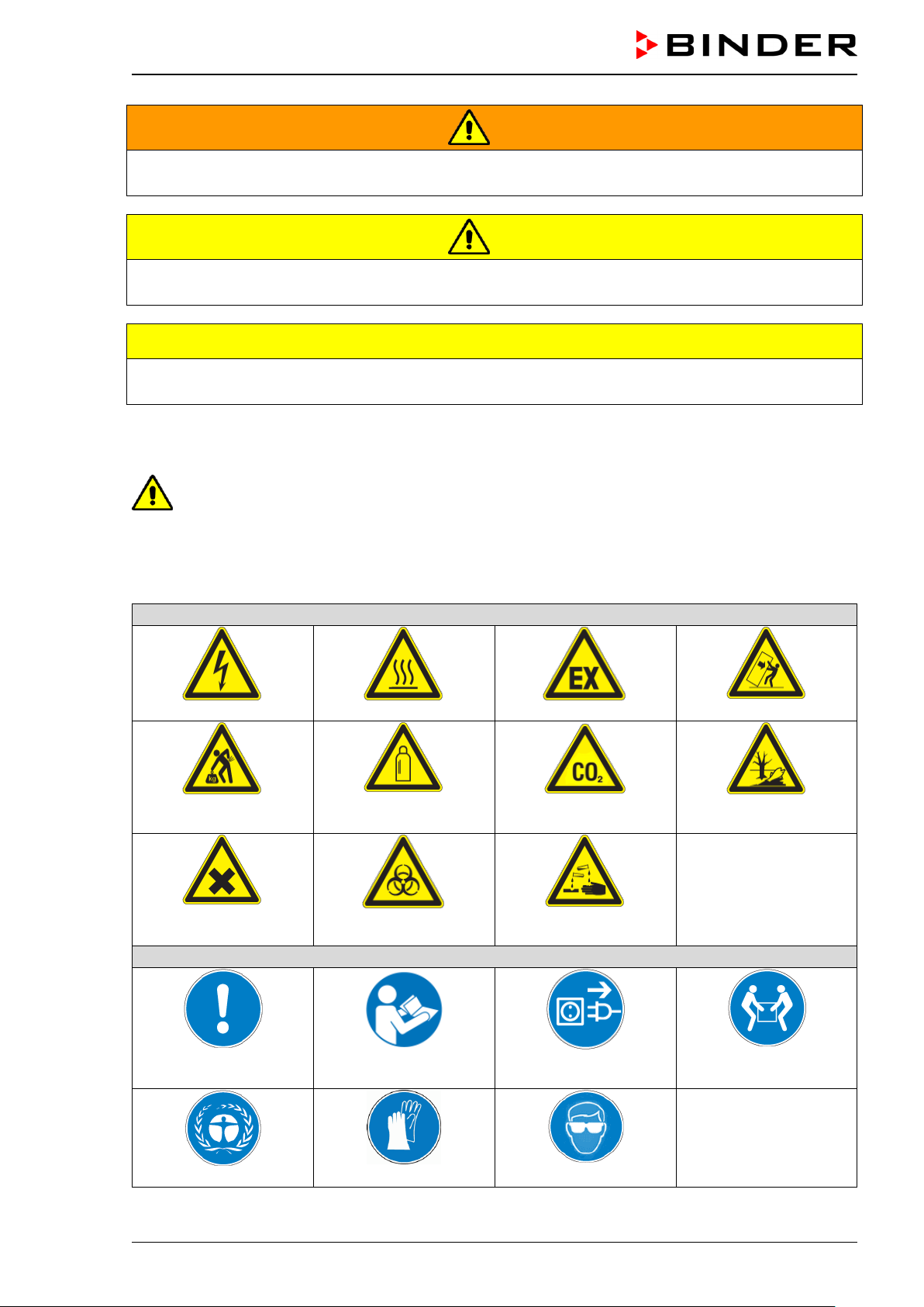
1.2.3 Pictograms
Warning signs
Electrical hazard
Hot surface
Explosive Atmosphere
Stability hazard
Lifting hazard
Gas cylinders
CO
2
suffocation and
poisoning hazard
Pollution Hazard
Harmful substances
Biohazard
Risk of corrosion and /
or chemical burns
Mandatory action signs
Mandatory regulation
Read operating
instructions
Disconnect the power
plug
Lift with several persons
Environment protection
Wear protective gloves
Wear safety goggles
C 150 (E2) 12/2012 page 11/90
Prohibition signs
Do NOT touch
Do NOT spray with
water
Do NOT climb
Information to be observed in order to ensure optimum function of the product.
1.2.4 Word message panel structure
Type / cause of hazard.
Possible consequences.
Instruction on how to avoid the hazard: prohibition
Instruction on how to avoid the hazard: mandatory action
Observe all other notes and information not necessarily emphasized in the same way, in order to avoid
disruptions that could result in direct or indirect injury or property damage.
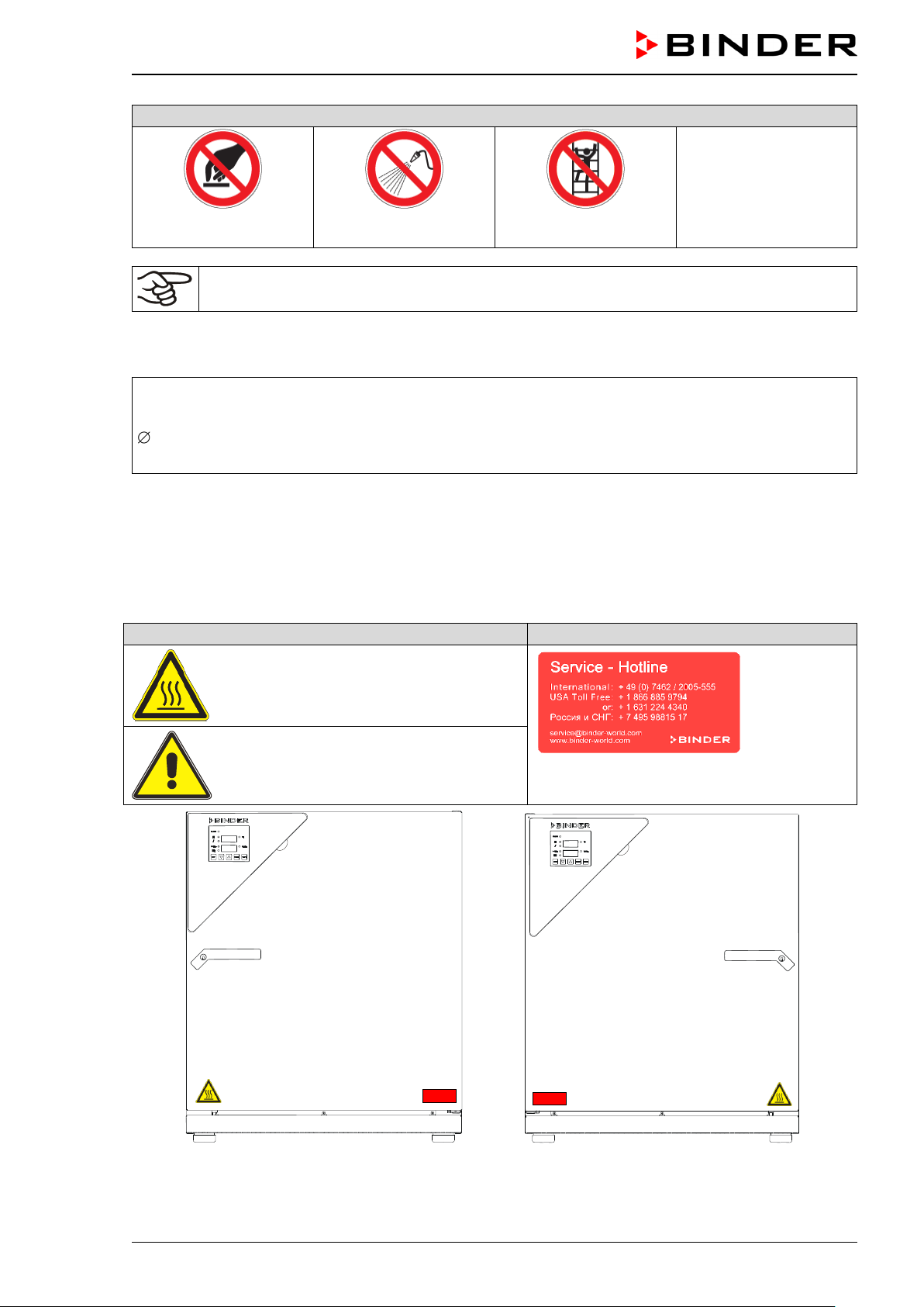
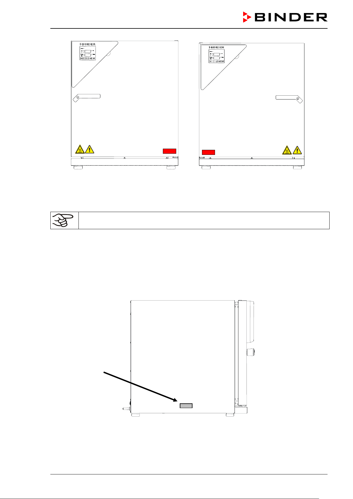
1.3 Localization / position of safety labels at the unit
The following labels are located on the unit:
Pictograms (Warning signs)
Service label
Hot surface
Risk of injury (C 150-UL only)
Figure 1: Position of labels on the CO
2
incubator
C 150 (door hinged right)
Figure 2: Position of labels on the CO
2
incubator
C 150 (door hinged left)
C 150 (E2) 12/2012 page 12/90
Figure 3: Position of labels on the CO
2
incubator
C 150-UL (door hinged right)
Figure 4: Position of labels on the CO
2
incubator
C 150-UL (door hinged left)
Keep safety labels complete and legible.
Replace safety labels that are no longer legible. Contact BINDER Service for these replacements.
1.4 Type plate
Figure 5: Position of type plate
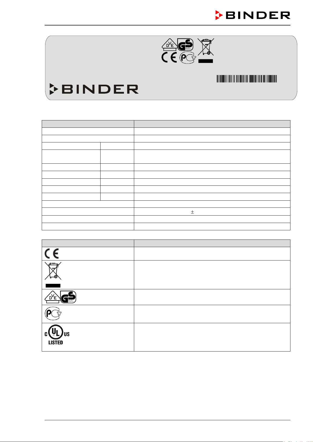
C 150 (E2) 12/2012 page 13/90
Figure 6: Type plate C 150 (standard unit)
Indications of the type plate
Information
BINDER
Manufacturer: BINDER GmbH
C 150
Model C 150
Serial No.
00-00000
Serial No. 00-00000
Nominal temperature
190 °C
374°F
Nominal temperature
Enclosure protection
IP 20
IP type of protection 20 acc. to EN 60529
Temp. safety device
DIN 12880
Temperature safety device acc. to standard DIN 12880
Class
3.1
Temperature safety device, class 3.1
Art. No.
9040-0078
Art. No. 9040-0078
Project No.
---
(Special application acc. to project no.)
1,40 kW
Nominal power 1.40 kW
230 V 1 N ~
Nominal voltage 230 V 10 %, single-phase unit
6,1 A
Nominal current 6.1 Amp
50/60 Hz
Power frequency 50/60 Hz
Symbol on the type plate
Information
CE conformity marking
Electrical and electronic equipment manufactured / placed on
the market in the EC after 13 August 2005 and to be disposed of
in a separate collection according to directive 2002/96/EC on
waste electrical and electronic equipment (WEEE).
VDE-GS certification mark
The equipment is certified in the GOST R certification system of
GOSTSTANDARD Russia.
LABORATORY EQUIPMENT
43KM
(C 150-UL only)
The equipment is certified by Underwriters Laboratories Inc.®
according to standards UL 61010A-1, UL 61010A-2-10, CSA
C22.2 No. 1010.1-92, and CSA C22.2 No. 1010.2.010-94.
Nominal temperature
190 °C
1,40 kW
374°F
230 V 1 N ~
Enclosure protection
Temp. safety device
IP 20
DIN 12880
6,1 A
50/60 Hz
Class
3.1
Art. No.
9040-0078
US PATS 4585923 / 5222612 / 5309981
Project No.
5405194 / 5601143 / 5773287 / 6079403
D 78532 Tuttlingen / Germany
Tel. + 49 (0) 7462/ 2005-0
Internet: www.binder-world.com
C 150 Serial No. 00-00000
Made in Germany
C 150 (E2) 12/2012 page 14/90
1.5 General safety instructions on installing and operating the CO
2
incubator
With regard to operating the CO
2
incubator C 150 and to the installation location, please observe the
guideline BGI/GUV-I 850-0 on safe working in laboratories (formerly BGR/GUV-R 120 or ZH 1/119 la-
boratory guidelines issued by the employers’ liability insurance association) (for Germany).
BINDER GmbH is only responsible for the safety features of the unit provided skilled electricians or quali-
fied personnel authorized by BINDER perform all maintenance and repair, and if components relating to
chamber safety are replaced in the event of failure with original spare parts.
To operate the unit, use only original BINDER accessories or accessories from third-party suppliers au-
thorized by BINDER. The user is responsible for any risk caused by using unauthorized accessories.
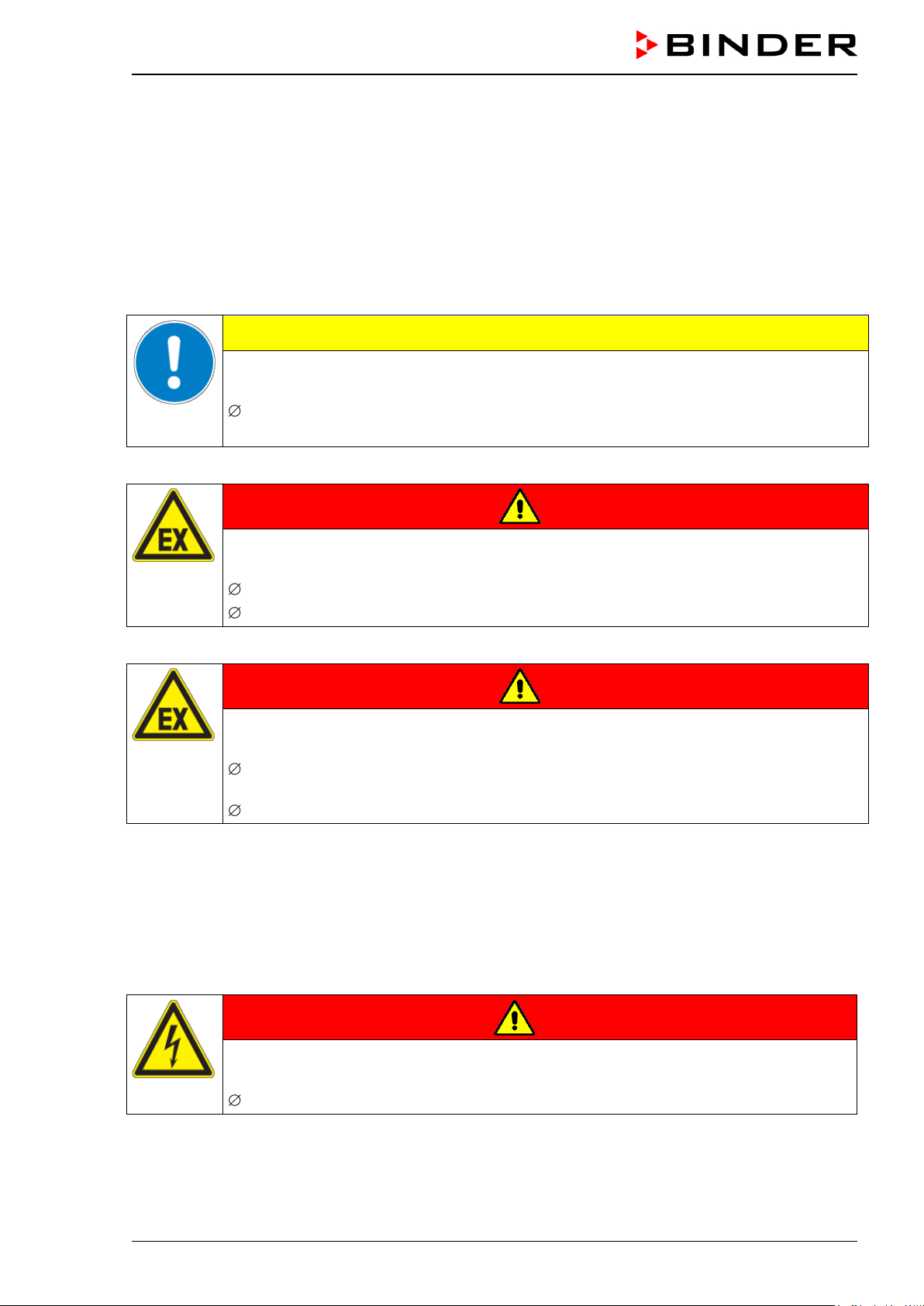
CAUTION
Danger of overheating.
Damage to the unit.
Do NOT install the unit in unventilated recesses.
Ensure sufficient ventilation for dispersal of the heat.
Do not operate the CO
2
incubator C 150 in hazardous locations.
DANGER
Explosion hazard.
Danger of death.
Do NOT operate the unit in potentially explosive areas.
KEEP explosive dust or air-solvent mixtures AWAY from the unit.
The CO
2
incubator C 150 does not dispose of any measures of explosion protection.
DANGER
Explosion hazard.
Danger of death.
Do NOT introduce any substance into the CO
2
incubator which is combustible or explo-
sive at working temperature.
NO explosive dust or air-solvent mixture in the inner chamber.
Any solvent contained in the charging material must not be explosive or inflammable. I.e., irrespective of
the solvent concentration in the steam room, NO explosive mixture with air must form. The temperature
inside the chamber must lie below the flash point or below the sublimation point of the charging material.
Familiarize yourself with the physical and chemical properties of the charging material, as well as the
contained moisture constituent and its behavior with the addition of heat energy and humidity.
Familiarize yourself with any potential health risks caused by the charging material, the contained mois-
ture constituent or by reaction products that may arise during the temperature process. Take adequate
measures to exclude such risks prior to putting the CO
2
incubator into operation.
DANGER
Electrical hazard.
Danger of death.
The unit must NOT become wet during operation or maintenance.
C 150 (E2) 12/2012 page 15/90
The CO
2
incubators were produced in accordance with VDE regulations and were routinely tested in ac-
cordance to VDE 0411-1 (IEC 61010-1).
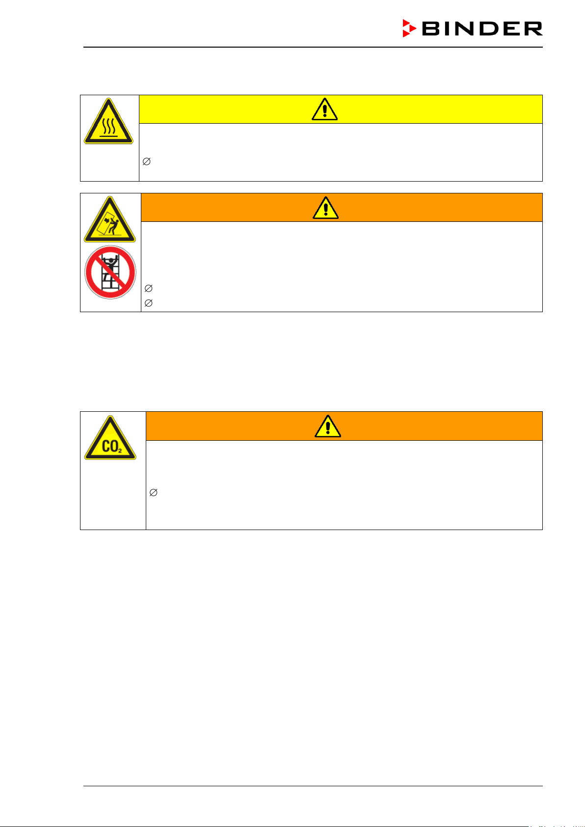
CAUTION
The glass door and the inner chamber will become hot during operation.
Danger of burning.
Do NOT touch the glass door, the inner surfaces or the charging material during opera-
tion.
WARNING
Stability hazard.
Danger of injury.
Damage to the unit and the charging material.
Housing cover breakaway.
Do NOT climb on the lower housing cover.
Do NOT load the lower housing cover with heavy objects while the unit door is open.
1.6 Precautions when working with CO
2
gas
Carbon dioxide (CO
2
) in high concentrations is hazardous to health. It is colorless and almost odorless
and therefore practically imperceptible. Vent out any CO
2
gas that may escape via good room ventilation
or a suitable connection to an exhaust system. We recommend installing a CO
2
warning system.
WARNING
High concentration of CO
2
(> 4 Vol.-%).
Risk of death by suffocation.
Danger of poisoning.
Do NOT set up units in non-ventilated recesses
Ensure technical ventilation measures
Observe the relevant regulations for handling CO
2
.
C 150 (E2) 12/2012 page 16/90
1.7 Precautions when handling gas cylinders
General information for safe handling of gas cylinders:
Store and use gas cylinders only in well-ventilated locations.
Open the gas cylinder valve slowly to avoid pressure surges
Secure gas cylinders during storage and use against falling (chaining).
Transport gas cylinders with a cylinder cart, do not carry, roll, or throw them.
Always close the valve even with apparently empty cylinders; screw on the cap when not in
use. Return gas cylinders with the valve closed.
Do not open gas cylinders by force. Mark them when damaged
Protect gas cylinders against fire, e.g. do not store together with flammable liquids
Observe relevant regulations for dealing with gas cylinders.
Secure the gas cylinders against falling and other mechanical damage.
WARNING
Safety valve tearing off.
Sudden release of the stored pressure energy.
Risk of injury.
Secure gas cylinders against falling (chaining).
Transport gas cylinders with a cylinder cart.
The valve of the gas cylinder always must be closed before screwing on or unscrewing the gas hose.
WARNING
Opening the cylinder valve when the cylinder is not connected.
Sudden release of the stored pressure energy.
Risk of injury.
Close the gas cylinder valve before connecting or removing the gas hose.
After connecting the gas cylinder, check all gas connections for leaks (e.g. with leak spray or
diluted soap solution).
1.8 Intended use
Series C 150 incubators are suitable for the cultivation of mammal cells under typical conditions of ap-
prox. 37 °C / 98.6 °F. The incubator permits setting defined pH conditions by common NaHCO
3
buffer
systems of commercial cell media by keeping an exact CO
2
atmosphere inside. C 150 incubators guaran-
tee high humidity inside to avoid osmolarity increasing caused by the evaporation of the cell media.
Observing the instructions in this operating manual and conducting regular maintenance work
(chap. 16) is part of the intended use.
Other applications are not approved.
WARNING: If customer should use a BINDER chamber running in non-supervised continu-
ous operation, we strongly recommend in case of inclusion of irrecoverable specimen or
samples to split such specimen or samples and store them in at least two chambers, if this is
feasible.

C 150 (E2) 12/2012 page 17/90
Always use proper protective equipment (clothing, gloves, safety glasses, etc.).
Always follow good hygienic practices according to GLP/SOP protocols.
Each individual operating the C 150 incubator is responsible for his or her own safety
2. Unit description
The CO
2
incubators C 150 are equipped with a microprocessor controller for temperature and CO
2
levels
and a digital display accurate to one-tenth of a degree resp. 0.1 vol.-%
The inner chamber, the pre-heating chamber and the inside of the doors are all made of stainless steel
(material no. 1.4301 (V2A) in Germany). The inner surfaces are smooth and therefore easy to clean. The
inner chamber is deep-drawn from one piece, polished (suitable for pharmaceutical applications) and has
no welds or inaccessible corners. The hinges and the seal of the inner glass door are glued from the out-
side to aid cleaning of the inner chamber. When operating the chamber at high temperatures (steriliza-
tion), the impact of the oxygen in the air may cause discoloration of the metallic surfaces (yellowish-brown
or blue) by natural oxidation processes. These colorations are harmless and will in no way impair the
function or quality of the unit.
The perforated shelves are made of stainless steel. You can insert a maximum of six shelves.
The housing is RAL 7035 powder-coated. All corners and edges are also completely coated.
The heating system of the CO
2
incubator permits hot-air auto-sterilization at 190 °C / 374°F. Thus, a tem-
perature of at least 180 °C / 356°F is maintained on all internal surfaces, resulting in sterilization of the
entire inner chamber.
Thanks to the standard safety device (class 3.1 according to DIN 12880), the set temperature is main-
tained in case of failure.
The gas enters the chamber via a fine filter (aseptic filter) with a high filtration efficiency that also filters
the smallest particles.
A highly precise, drift-free CO
2
infrared measuring system in combination with the permanent mixture of
CO
2
gas through a special proprietary gas mixing head developed by BINDER allows precise and con-
stant CO
2
concentrations for long periods. This creates optimum growth conditions for cultures. The CO
2
sensor can be removed from the inner chamber by hand and cleaned with suitable detergents if needed.
The CO
2
incubator can be operated in a temperature range from 7 degrees above ambient temperature
up to +50 °C / 122°F and a CO
2
range of 0 vol.-% up to 20 vol.-%.
2.1 The CO
2
measuring principle
Fast reaction times, as well as the highest accuracy and selectivity, characterize the CO
2
measuring pro-
cedure of the C 150 incubator series. The accuracy of the CO
2
measuring system is based on a single-
beam infrared measuring cell, which measures in differential mode using the permanently alternating
transmission feature of its semi-conductor filter.
Due to this highly developed single-beam principle with Fabry-Perot interferometer (FPI), disturbance
variables and aging phenomena in the measuring system are almost completely eliminated, so that this
measuring system, in contrast to other measuring procedures, remains practically drift-free between cali-
brations and is absolutely selective for CO
2
.
The CO
2
measuring cell contains a measuring section inside, in which the absorption of infrared light
depends on the number of CO
2
molecules in the beam path. This number of CO
2
molecules changes with
the ambient pressure in relation to a constant volume. The distances between the molecules are conse-
quently pressure-dependent. The collision frequency of the IR-beam with CO
2
molecules increases there-
fore by increasing pressure. For this reason, the ambient pressure must be compensated in order to cor-
rect the display reading of the CO
2
concentration in vol.-%. This is achieved by entering the altitude of the
site above the sea (chap. 8.1).
C 150 (E2) 12/2012 page 18/90
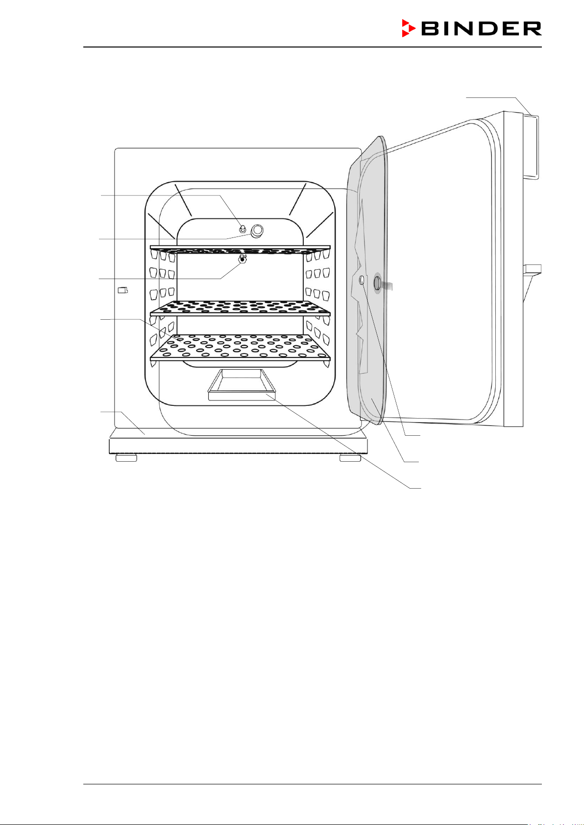
2.2 Unit overview
Figure 7: CO
2
incubator C 150 (door hinged right)
(1) Triangle instrument panel with RP1 controller for temperature and CO
2
and main power switch (2)
(3) Gas mixing head CO
2
(4) CO
2
sensor
(5) Pt 100 temperature sensor
(6) Shelves
(7) Lower housing cover
(8) Silicone measuring port
(9) Inner glass door
(10) Water pan
(3)
(4)
(5)
(6)
(7)
(1)
(8)
(9)
(10)

C 150 (E2) 12/2012 page 19/90
2.3 Connection panel at the rear of the unit
(11) (12) (13) (14) (15)
Figure 8: Rear connection panel C 150
(11) Power cable
(12) Miniature fuse
(13) Connection socket for zero-voltage relay alarm contact
(14) Quick acting closure socket for CO
2
gas cylinder
(15) Ethernet interface for computer communication (option)
2.4 Triangle instrument panel C 150
Figure 9: Triangle instrument panel with RP1 controller
(2) Main power switch with protruding plastic shield (protection against turning off unintentionally)
(2)
C 150 (E2) 12/2012 page 20/90
2.5 Unit doors
The outer door of the C 150 is equipped with a heater on its inner side. The door must be closed while the
unit is operating normally in order to ensure stable climatic conditions in the inner chamber.
An additional glass door enables viewing of the samples without disturbing the temperature in the interior
and contaminating the samples sealing the interior of the C 150.
When the outer door is open, the CO
2
intake valve automatically closes.
Delay time for the temperature and CO
2
tolerance range alarm :
After closing the outer door, the tolerance range alarm is turned off for a programmable delay
time. This prevents alarms being constantly triggered during the unstable operating phase
after opening the outer door.
3. Completeness of delivery, transportation, storage, and installa-
tion
3.1 Unpacking, and checking equipment and completeness of delivery
After unpacking, please check the unit and its optional accessories, if any, based on the delivery receipt
for completeness and for transportation damage. Inform the carrier immediately if transportation damage
has occurred.
The final tests of the manufacturer may have caused traces of the shelves on the inner surfaces. This has
no impact on the function and performance of the unit.
Please remove any transportation protection devices and adhesives in/on the unit and on the doors and
remove the operating manuals and accessory equipment.
For transport purpose, a silica gel bag for drying purpose was added. Do not eat! Do not open the silica
gel bag and dispose of it with normal waste.
Remove any protective lamination sheet on the inner metal surfaces prior to commissioning.
CAUTION
Sliding or tilting of the unit.
Damage to the unit.
Risk of injury by lifting heavy loads.
Do NOT lift or transport the unit using the door handle, the door or the lower housing.
Lift the unit from the pallet at the four lower corners with the aid of four people.
If you need to return the unit, please use the original packing and observe the guidelines for safe lifting
and transportation (chap. 3.2).
For disposal of the transport packing, see chap. 17.1.
Note on second-hand units (Ex-Demo-Units):
Second-hand units are units that were used for a short time for tests or exhibitions. They are thoroughly
tested before resale. BINDER ensures that the chamber is technically sound and will work flawlessly.
Second-hand units are marked with a sticker on the unit door. Please remove the sticker before commis-
sioning the unit.
C 150 (E2) 12/2012 page 21/90
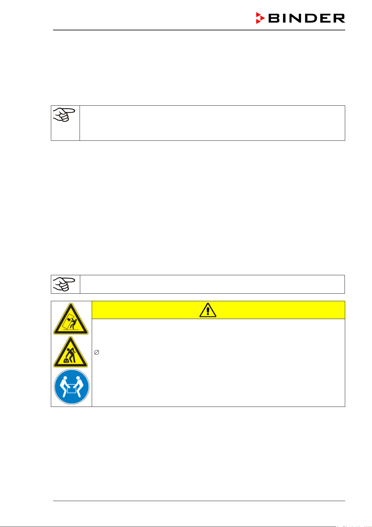
3.2 Guidelines for safe lifting and transportation
After operation, please observe the guidelines for temporarily decommissioning the unit (chap. 17.2).
Empty the water pan before moving the incubator. In case of any spilling of the contents, shut down the
incubator and dry it out carefully and completely
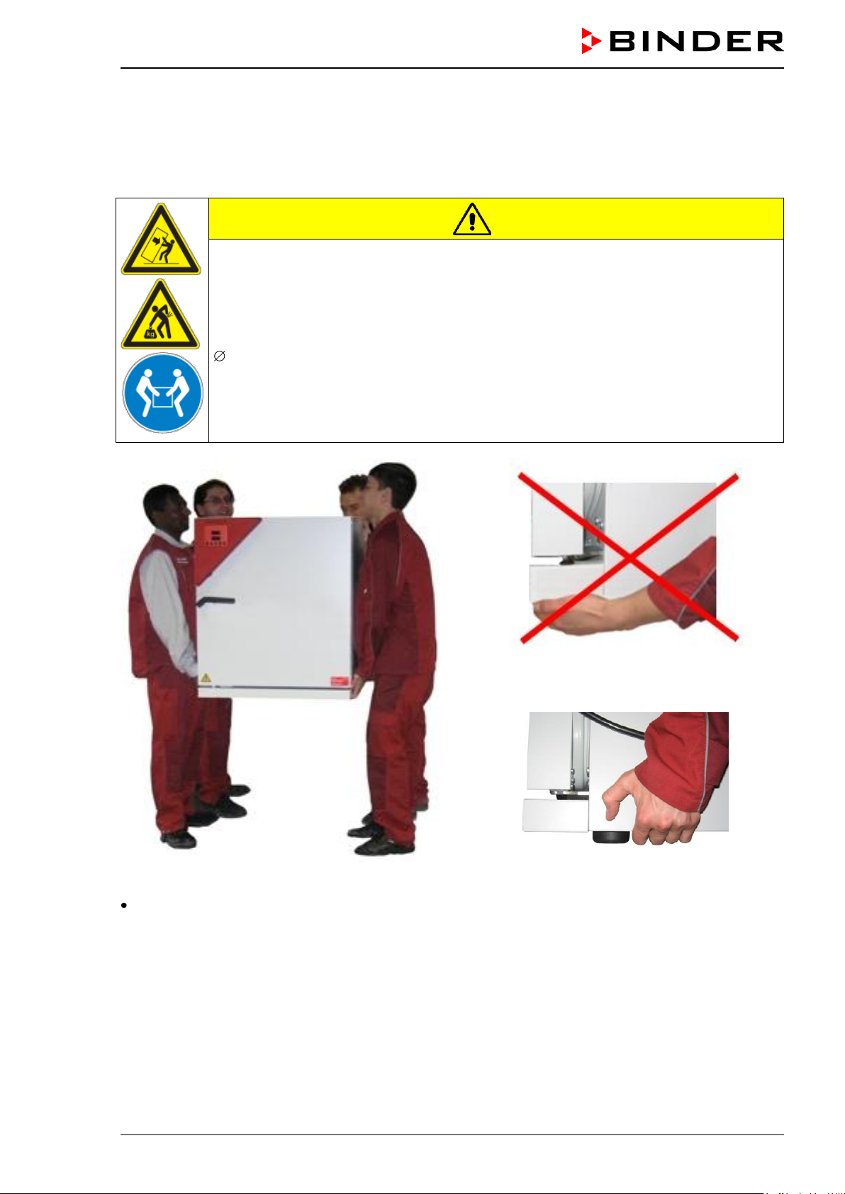
CAUTION
Sliding or tilting the unit.
Damage to the unit.
Risk of injury by lifting heavy loads.
Transport the unit in its original packaging only.
Secure the CO
2
incubator with transport straps for transport.
Do NOT lift or transport the unit using the door handle, the door or the lower housing.
Lift the unit at the four lower corners with the aid of 4 people and place it on a rolling
pallet.
Move the unit to the desired location and lift it from the rolling pallet with the aid of four
people.
Figure 10: Lift the unit with the aid of 4 people
Figure 11: Incorrect lifting
Figure 12: Correct lifting
Permissible ambient temperature range for transport: -10 °C / 14°F to +60 °C / 140°F.
You can order transport packing and rolling pallets for transportation purposes from BINDER Service.
C 150 (E2) 12/2012 page 22/90
3.3 Storage
Intermediate storage of the unit is possible in a closed and dry room. Observe the guidelines for tempo-
rary decommissioning (chap. 17.2).
Permissible ambient temperature range for storage: -10 °C / 14°F to +60 °C / 140°F.
Permissible ambient humidity: max. 70% r.H., non-condensing
When after storage in a cold location you transfer the unit to its warmer installation site, condensation
may form in the inner chamber, on the housing or in the sensor compartment of the CO
2
measurement.
Before start-up, wait at least one hour until the CO
2
incubator has attained ambient temperature and is
completely dry.
3.4 Location of installation and ambient conditions
Notes on the location of installation
Set up the CO
2
incubator on a flat, even surface, free from vibration and in a well-ventilated, dry location.
The chambers are designed for setting up inside a building (indoor use).
Freestanding C 150 incubators are suitable for installation on tables or on the optionally available stand.
Note: The site of installation must be capable of supporting the unit’s weight (see technical data, chap.
19.4).
Align the unit using a spirit level to ensure even covering of the cell-cultures with the medium. For this
purpose, manually adjust the four incubator feet.
In order to avoid contamination, never place the unit directly on the floor.
CAUTION
Danger of overheating.
Damage to the unit.
Do NOT set up units in non-ventilated recesses.
Ensure sufficient ventilation for dispersal of the heat.
To completely separate the unit from the power supply, you must disconnect the power plug. Install the
unit in a way that the power plug is easily accessible and can be easily pulled in case of danger.
Do not install or operate the CO
2
incubator C 150 in potentially explosive areas.
DANGER
Explosion hazard.
Danger of death.
Do NOT operate the unit in potentially explosive areas.
KEEP explosive dust or air-solvent mixtures AWAY from the vicinity of the unit.
Ambient conditions
Permissible ambient temperature range for operation: +18 °C / 64.4 °F up to +30 °C / 86 °F. At elevat-
ed ambient temperature values, fluctuations in temperature can occur.
Ideal ambient temperature: by at least 7 °C / 12.6 °F below the intended working temperature. E.g.,
working temperature 37 °C / 98.6 °F – resulting permitted ambient temperature 30 °C / 86°F and lower
In the event of working temperatures of less than 7 °C / 12.6 °F above the ambient temperature, the set
point can be exceeded.
The ambient temperature should not be substantially higher than the indicated ambient tem-
perature of +25 °C / 77°F to which the specified technical data relate. For other ambient condi-
tions, deviations from the indicated data are possible.
C 150 (E2) 12/2012 page 23/90
Avoid direct solar radiation on the unit.
Permissible ambient humidity: 70% r.H. max., non-condensing.
Installation height: max. 2000 m / 6561.7 ft above sea level. After the incubator has been turned on for
the first time, enter the altitude of the site above sea level into the RP1 controller (chap. 8.1).
Wall distances: rear 100 mm / 3.94 in, sides 50 mm / 1.97 in.
Notes on handling carbon dioxide (CO
2
)
Carbon dioxide (CO
2
) in high concentrations is hazardous to health. It is colorless and almost odorless
and therefore practically imperceptible. Vent out any CO
2
gas that may escape via good room ventilation
or a suitable connection to an exhaust system. We recommend installing a CO
2
warning system.
WARNING
High concentration of CO
2
(> 4 Vol.-%).
Danger of death by suffocation.
Danger of poisoning.
Do NOT set up units in non-ventilated recesses.
Ensure technical ventilation measures.
Observe the relevant regulations for handling CO
2
.
Observe the occupational exposure limit OEL for CO
2
set by the national authorities (formerly maxi-
mum permitted workplace concentration). Check compliance when operating all units located in the room.
OEL for Germany: 5000 ml/m3 (ppm) = 0,5 Vol.-%
CO
2
lost with each door opening: about 16.4 g, i.e. 0.0084 cubic meters / 0.296 cubic feet (under nor-
mal pressure)
CO
2
lost during 12h at 5 vol.-% without door opening: approx. < 2 g, i.e. 0.001 cubic meters / 0.035
cubic feet (under normal pressure 1013 mbar / 14.7 psi)
An example of how to evaluate laboratory volume and air change rate:
Question: Is an air change rate of 1/h sufficient for a lab with a volume of 100 cubic meters / 3,531.5
cubic feet with 10 incubators C 150, opened 4 times per hour?
Calculation: CO
2
concentration = CO
2
lost by door opening, multiplied by 10 units, multiplied by 4 door
openings per hour, divided by lab volume
0.0084 cubic meters x 10 x 4 div. 100 cubic meters = 0.00336, i.e. 0.336% or 3360 ppm.
0.296 cubic feet x 10 x 4 div. 3,531.5 cubic feet = 0.00336, i.e. 0.336% or 3360 ppm.
Result: The maximum permissible value of 5000 ppm is not exceeded under these operation conditions.
4. Installation and connections
4.1 Shelves
You can put the shelves in different positions at the line of channel beads in the inner chamber. Hold the
shelf straight and then insert it so it will go smoothly inside the unit.
Permitted shelf loads:
Maximum load on one single shelf: 10 kg / 22 lb
Maximum total load on all shelves: 30 kg / 66 lb
C 150 (E2) 12/2012 page 24/90
4.2 CO
2
sensor
4.2.1 General notes
Connect or remove the CO
2
sensor without rotating and only when the incubator is turned off. Remove
the CO
2
sensor before removing or replacing its filter cap. The PTFE filter of the CO
2
sensor prevents dirt
and humidity from intruding into the measuring cell. It is available as a spare part. Replace it whenever it
is damaged or soiled.
The accuracy of the indicated values of CO
2
depends on the ambient air pressure (approx.
0.08 vol.-% per 10 mbar / 0.15 psi). In order to compensate this effect when measuring the
CO
2
concentration, the altitude of the installation site above sea level can be entered into the
controller (chap. 8.1).
The CO
2
sensor is temperature resistant up to a maximum temperature of 60 °C / 140 °F.
CAUTION
Excess temperature.
Damage to the CO
2
sensor.
Do NOT autoclave the CO
2
Sensor.
Do NOT expose the CO
2
sensor to hot-air sterilization.
The CO
2
sensor head was especially adjusted for the specific chamber. To avoid confusion, an adhesive
label with a serial number is adhered to the sensor head. When exchanging the sensor, you must repeat
the CO
2
adjustment.
CAUTION
Different CO
2
sensor.
Invalid calibration.
Do NOT change the CO
2
sensor head.
Note down the serial number of the CO
2
sensor.
Avoid strong shocks when handling the CO
2
sensor.
CAUTION
Shocks of the CO
2
sensor.
Damage to the CO
2
sensor.
Avoid strong shocks of the CO
2
sensor (by putting it down hard, or dropping).
4.2.2 Connecting the CO
2
sensor
Turn off the unit. Open the door of the inner chamber and plug the CO
2
sensor (4) without rotating into the
connection socket located in the upper part of the rear of the inner chamber.
The sensor must click in correctly and sit tightly in the connection socket.
CAUTION
Connecting or removing the CO
2
sensor during operation.
Damage to the CO
2
sensor.
Connect or remove the CO
2
sensor only with the unit turned off.
C 150 (E2) 12/2012 page 25/90
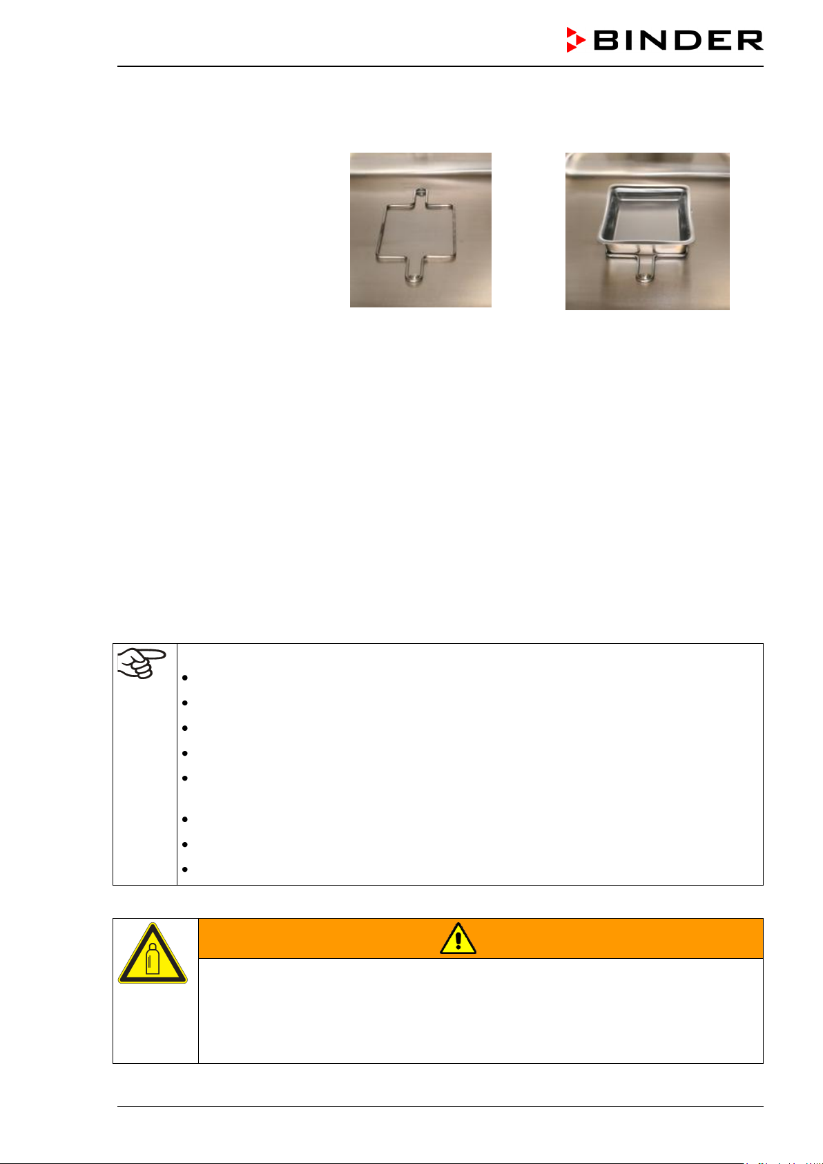
4.3 Water pan
The water pan permits high humidity without condensation on the inner walls of the incubator.
Place the positioning frame
on the two marks at the bot-
tom of the inner chamber.
Then put the water pan in
the positioning frame. Make
sure that the water pan has
firm contact with the inner
chamber bottom and rests
tightly on it.
Figure 13: Placed positioning frame
Figure 14: Placed water pan
Fill the water pan with 300 ml of distilled, sterilized water.
We recommend cleaning (chap. 15.1) and refilling the pans 2 to 3 times a week. For evacuation, remove
the water pan.
We recommend using distilled, sterile water to achieve optimum growth results. Any corrosive damage
that may arise following use of water of different quality or by additives is excluded from the liability
agreement.
If required, you can add microbiologically inhibiting substances such as copper chips, copper sulphate or
ethylene diamine tetra-vinegar acid (EDTA) in a concentration of 1 to 5 mmol/l.
Empty the water pan before moving the incubator. In case of the contents spilling, immediately shut down
the incubator and dry it carefully and completely.
4.4 Gas connection
General information for safe handling of gas cylinders:
Store and use gas cylinders only in well ventilated areas.
Open the gas cylinder valve slowly to avoid pressure surges
Secure gas cylinders during storage and use against falling (chaining).
Transport gas cylinders with a cylinder cart, do not carry, roll, or throw them
Always close the valve even with apparently empty cylinders; screw on the cap when not in
use. Return gas cylinders with the valve closed
Do not open gas cylinders by force. Mark them when damaged
Protect gas cylinders against fire, e.g. do not store together with flammable liquids
Observe relevant regulations for dealing with gas cylinders.
Secure the gas cylinders against falling and other mechanical damage.
WARNING
Safety valve tearing off.
Sudden release of the stored pressure energy.
Risk of injury.
Secure gas cylinders against falling (chaining).
Transport gas cylinders with a cylinder cart.

C 150 (E2) 12/2012 page 26/90
The valve of the gas cylinder always must be closed before screwing on or unscrewing the gas hose.
WARNING
Opening the cylinder valve when the cylinder is not connected.
Sudden release of the stored pressure energy.
Risk of injury.
Close the gas cylinder valve before connecting or removing the gas hose.
After connecting the gas cylinder, check all gas connections for leaks (e.g. with leak spray or
diluted soap solution).
4.4.1 Connecting the CO
2
gas cylinder
Carbon dioxide (CO
2
) in high concentrations is hazardous to health. It is colorless and almost odorless
and therefore practically imperceptible. Vent out any CO
2
gas that may escape via good room ventilation
or a suitable connection to an exhaust system. We recommend installing a CO
2
warning system.
WARNING
High concentration of CO
2
(> 4 Vol.-%).
Danger of death by suffocation.
Danger of poisoning.
Do NOT set up units in non-ventilated recesses.
Ensure technical ventilation measures.
Observe the relevant regulations for handling CO
2
.
The CO
2
gas necessary for operation must have a technical grade of 99.5 %.
The gas connections must be established by qualified personnel who are trained in handling
the respective gases and familiar with the required safety measures.
C 150 (E2) 12/2012 page 27/90
The following steps are required:
Ensuring the correct CO
2
output pressure
A gas supply pressure above 2.5 bar / 36 psi will result in unit damage.
Use a pressure reducer and make sure to avoid any excessive outlet pressure when connecting the
gas hose to the incubator.
The real outlet pressure of gas cylinders, sets of gas cylinders or central gas supplies am on the sec-
ond manometer must not exceed 2.5 bar / 36 psi.
CAUTION
Excessive outlet pressure > 2.5 bar / 36 psi.
Damage to the unit.
The outlet pressure must NOT exceed the indicated value of 2.5 bar / 36 psi.
Before connecting, check the outlet pressure on the pressure reducer of the cylin-
der.
Adjust the outlet pressure to 2.0 bar / 29 psi above the ambient pressure.
Observe the correct outlet pressure also when replacing the gas cylinders.
Establishing the connection to the incubator
Connect the supplied gas hose (internal diameter 6 mm / 0.24 inches) to the pressure reducer of the
gas cylinders or central gas supply and secure the connection with the supplied hose clamp.
Connect the pre-assembled hose nozzle of the gas hose to the quick acting closure socket (14) DN 6
on the unit rear, as described in chap. 4.4.2.
Leak test
After connecting the gas cylinder, check all gas connections for leaks (e.g. with leak spray or diluted soap
solution).
The recovery times of the gas concentrations inside the chamber after opening the door are
indicated in the technical data (chap. 19.4) and refer to a connection pressure of 2.0 bar / 29
psi. Decreasing supply pressure will result in longer recovery times.
Conversion table for gas inlet pressures, bar – psi, see chap. 19.6.
 Loading...