


KBF LQC 240
Table of contents
 Loading...
Issue 07/2014 Art. No. 7001-0283
Operating Manual
APT.line™ KBF LQC (E5.3)
Constant climate chambers
with ICH compliant illumination and light dose detection
with program control and adjustable light cassettes
Model
Art. No.
KBF LQC 240 (E5.3)
9020-0277, 9120-0277
KBF LQC 720 (E5.3)
9020-0279, 9120-0279
BINDER GmbH
Address Post office box 102
D-78502 Tuttlingen
Tel. +49 7462 2005 0
Fax +49 7462 2005 100
Internet http://www.binder-world.com
E-mail info@binder-world.com
Service Hotline +49 7462 2005 555
Service Fax +49 7462 2005 93 555
Service E-Mail service@binder-world.com
Service Hotline USA +1 866 885 9794 or +1 631 224 4340 x3
Service Hotline Asia Pacific +852 390 705 04 or +852 390 705 03
Service Hotline Russia and CIS +7 495 988 15 16

KBF LQC (E5.3) 07/2014 page 2/114
EC – declaration of conformity
EG – KONFORMITÄTSERKLÄRUNG
EC - DECLARATION OF CONFORMITY
CE - DECLARATION DE CONFORMITE
Anbieter / Supplier / Fournisseur:
BINDER GmbH
Anschrift / Address / Adresse:
Im Mittleren Ösch 5, D-78532 Tuttlingen
Produkt / Product / Produit:
Konstantklimaschränke mit ICH konformer Beleuchtung und
Lichtdosiserfassung
Constant climate chambers with ICH compliant illumination and
light dose detection
Enceinte climatique pour des conditions constantes avec éclai-
rage conforme à l’ICH et détection de la dose de lumière
Typenbezeichnung / Type / Type:
KBF LQC 240, KBF LQC 720
Die oben beschriebenen Produkte sind konform mit folgenden EG-Richtlinien:
The products described above are in conformity with the following EC guidelines:
Les produits décrits ci-dessus sont conformes aux directives CE suivantes:
Niederspannungsrichtlinie
2006/95/EG
Low voltage directive
2006/95/EC
Directive basse tension
2006/95/CE
Richtlinie 2006/95/EG des Europäischen Parlaments und des Rates
vom 12. Dezember 2006 zur Angleichung der Rechtsvorschriften der
Mitgliedstaaten betreffend elektrische Betriebsmittel zur Verwendung
innerhalb bestimmter Spannungsgrenzen
Council Directive 2006/95/EC of 12 December 2006 on the harmoniza-
tion of the laws of Member States relating to electrical equipment de-
signed for use within certain voltage limits
Directive 2006/95/CE du Parlement Européen et du Conseil du 12 dé-
cembre 2006 concernant le rapprochement des législations des États
membres relatives au matériel électrique destiné à être employé dans
certaines limites de tension
EMV-Richtlinie
2004/108/EG
EMC Directive
2004/108/EC
Directive CEM
2004/108/CE
Richtlinie 2004/108/EG des Europäischen Parlaments und des Rates
vom 15. Dezember 2004 zur Angleichung der Rechtsvorschriften der
Mitgliedstaaten über die
elektromagnetische Verträglichkeit und zur
Aufhebung der Richtlinie 89/336/EWG.
Directive 2004/108/EC of the European Parliament and of the Council
of 15 December 2004 on the approximation of the laws of the Member
States relating to electromagnetic compatibility and repealing Directive
98/336/EEC.
Directive 2004/108/CE du Parlement Européen et du Conseil du 15
décembre 2004 relative au rapprochement des législations des États
membres concernant la compatibilité électromagnétique et abrogeant le
directive 98/336/CEE.
Die oben beschriebenen Produkte tragen entsprechend die Kennzeichnung CE.
The products described above, corresponding to this, bear the CE-mark
Les produits décrits ci-dessus, en correspondance, portent l’indication CE.
1 / 2

KBF LQC (E5.3) 07/2014 page 3/114
Die oben beschriebenen Produkte sind konform mit folgenden harmonisierten Normen:
The products described above are in conformity with the following harmonized standards:
Les produits décrits ci-dessus sont conformes aux normes harmonisées suivantes:
Sicherheit / safety / sécurité:
EN 61010-1:2010 Sicherheitsbestimmungen für elektrische Mess-, Steuer-, Regel- und
Laborgeräte – Teil 1: Allgemeine Anforderungen (DIN EN 61010-
1:2011, VDE 411-1:2011)
Safety requirements for electrical equipment for measurement, control,
and laboratory use – Part 1: General requirements (IEC 61010-1:2010,
BS EN 61010-1:2010)
Règles de sécurité pour appareils électriques de mesurage, de régula-
tion et de laboratoire – Partie 1: Prescriptions générales (CEI 61010-
1:2010, NF EN 61010:2011)
EN 61010-2-010:2003 Sicherheitsbestimmungen für elektrische Meß-, Steuer-, Regel- und
Laborgeräte – Teil 2-010: Besondere Anforderungen an Laborgeräte für
das Erhitzen von Stoffen (DIN EN 61010-2-010:2004)
Safety requirements for electrical equipment for measurement, control,
and laboratory use – Part 2-010: Particular requirements for laboratory
equipment for the heating of materials (IEC 61010-2-10:2005, BS EN
61010-2-10:2003)
Règles de sécurité pour appareils électriques de mesurage, de régula-
tion et de laboratoire – Partie 2-010 : Prescriptions particulières pour
appareils de laboratoire utilisés pour l’échauffement des matières (CEI
61010-2-10:2003, NF EN 61010-2-10:2005)
EMV / EMC / CEM:
EN 61326-1:2013 Elektrische Mess-, Steuer-, Regel- und Laborgeräte - EMV-
Anforderungen - Teil 1: Allgemeine Anforderungen (DIN EN 61326-
1:2013, VDE 0813-20-1:2013)
Electrical equipment for measurement, control and laboratory use -
EMC requirements - Part 1: General requirements (IEC 61326-1:2012,
BS EN 61326-1:2013)
Matériel électrique de mesure, de commande et de laboratoire - Exi-
gences relatives à la CEM - Partie 1: Exigences générales (CEI 61326-
1:2012, NF EN 61326-1:2013)
D-78532 Tuttlingen, 02.06.2014
BINDER GmbH
P. M. Binder
Geschäftsführender Gesellschafter
Managing Director
Directeur général
J. Bollaender
Leiter F & E
Director R & D
Chef de service R&D
2 / 2
KBF LQC (E5.3) 07/2014 page 4/114
Product registration

KBF LQC (E5.3) 07/2014 page 5/114
Content
EC – declaration of conformity ...................................................................................................................... 2
Product registration ....................................................................................................................................... 4
1. SAFETY .................................................................................................................. 8
1.1 Legal considerations ........................................................................................................................... 8
1.2 Structure of the safety instructions ...................................................................................................... 8
1.2.1 Signal word panel ..................................................................................................................... 8
1.2.2 Safety alert symbol ................................................................................................................... 9
1.2.3 Pictograms ................................................................................................................................ 9
1.2.4 Word message panel structure ............................................................................................... 10
1.3 Localization / position of safety labels on the unit ............................................................................. 10
1.4 Type plate ......................................................................................................................................... 12
1.5 General safety instructions on installing and operating the constant climate chamber .................... 13
1.6 Intended use ..................................................................................................................................... 15
1.7 Resistance of the humidity sensor against harmful substances ....................................................... 16
2. UNIT DESCRIPTION ............................................................................................ 17
2.1 Unit overview ..................................................................................................................................... 18
2.2 Lateral control panel, right side ......................................................................................................... 19
2.3 Lateral control panel, left side ........................................................................................................... 20
2.4 Instrument panel ............................................................................................................................... 21
3. COMPLETENESS OF DELIVERY, TRANSPORTATION, STORAGE, AND
INSTALLATION .................................................................................................... 21
3.1 Unpacking, and checking equipment and completeness of delivery ................................................ 21
3.2 Guidelines for safe lifting and transportation .................................................................................... 22
3.3 Storage .............................................................................................................................................. 23
3.4 Location of installation and ambient conditions ................................................................................ 24
4. INSTALLATION AND CONNECTIONS................................................................ 25
4.1 Spacers for rear wall distance ........................................................................................................... 25
4.2 Wastewater connection ..................................................................................................................... 26
4.3 Freshwater supply ............................................................................................................................. 27
4.3.1 Automatic fresh water supply via water pipe .......................................................................... 27
4.3.2 Manual fresh water supply via external freshwater can (option) ............................................ 28
4.3.3 Connection kit for connection to the water main .................................................................... 28
4.3.4 Safety kit: Hose burst protection device with reflux protection device (available via BINDER
Individual) ................................................................................................................................ 29
4.4 Electrical connection ......................................................................................................................... 30
4.5 Installation and connection of the light cassettes ............................................................................. 31
4.6 Connecting the light sensors ............................................................................................................. 32
5. START UP ............................................................................................................ 33
5.1 Function overview of the MB1 display program controller ................................................................ 33
5.2 Operating modes ............................................................................................................................... 34
5.3 Performance after power failures ...................................................................................................... 34
5.4 Turning on the unit ............................................................................................................................ 35
6. SETTINGS OF THE MB1 CONTROLLER............................................................ 36
6.1 Selection of the MB1 controller’s menu language ............................................................................ 36
6.2 Function overview of the MB1 program controller displays .............................................................. 37
6.3 Menu settings in the “User-settings” menu ....................................................................................... 38
6.4 Menu settings in the “User Level” menu ........................................................................................... 39

KBF LQC (E5.3) 07/2014 page 6/114
7. GRAPHIC REPRESENTATION OF THE HISTORICAL MEASUREMENT
(CHART RECORDER FUNCTION) ..................................................................... 40
7.1 Setting the storage rate ..................................................................................................................... 42
8. MANUAL MODE ................................................................................................... 43
8.1 Entering the set point values ............................................................................................................. 43
8.2 Entering the set point values when operating without illumination ................................................... 45
8.3 Performance after power failure in Manual Mode ............................................................................. 45
9. FUNCTION OF LIGHT MEASUREMENT, AND INTEGRATION: LIGHT
QUANTUM CONTROL ......................................................................................... 46
9.1 Illumination measurement and temporal integration ......................................................................... 46
9.2 Toggling between displays of actual and integrated values ............................................................. 47
10. PROGRAM OPERATION OF THE TEMPERATURE, AND HUMIDITY
CONTROLLER ..................................................................................................... 48
10.1 Overview menu-based program entry .............................................................................................. 48
10.2 Entry of temperature values and fan speed ...................................................................................... 49
10.3 Entry of humidity values .................................................................................................................... 51
10.4 Selecting between set-point ramp and set-point step ....................................................................... 52
10.5 Program entry as set-point ramp or as set-point step ...................................................................... 53
10.6 Advice for the programming of the different temperature or humidity transitions ............................. 55
10.7 Repetition of a section or several sections within a program ........................................................... 56
10.8 Performance after power failure in Program Mode ........................................................................... 56
10.9 Starting a previously entered program .............................................................................................. 57
10.10 Deleting a program............................................................................................................................ 57
10.11 Template for temperature profile ....................................................................................................... 58
10.12 Template for humidity profile ............................................................................................................. 59
10.13 Program table template for temperature and fan speed rate ............................................................ 60
10.14 Program table template for humidity ................................................................................................. 61
11. TEMPERATURE SAFETY DEVICES ................................................................... 62
11.1 Over temperature protective device (class 1) ................................................................................... 62
11.2 Safety controller (temperature safety device class 3.1) .................................................................... 62
11.2.1 Safety controller set-point types ............................................................................................. 62
11.2.2 Checking and setting safety controller set-point type and safety controller set-point ............ 63
11.3 Temperature safety device class 3.3 (DIN 12880) (option) .............................................................. 64
11.3.1 Temperature safety device class 3.1 ...................................................................................... 65
11.3.2 Temperature safety device class 3.2 ...................................................................................... 66
12. NOTIFICATION AND ALARM FUNCTIONS ........................................................ 67
12.1 Notification and alarm system overview (auto diagnosis system) .................................................... 67
12.2 Messages concerning the humidity system ...................................................................................... 69
12.3 Resetting the notification or alarm messages ................................................................................... 70
13. HUMIDITY SYSTEM ............................................................................................. 71
13.1 Function of the humidifying and dehumidifying system .................................................................... 73
14. DEFROSTING AT REFRIGERATING OPERATION ............................................ 74
15. ICH COMPLIANT ILLUMINATION ACCORDING TO CPMP/ICH/279/95 (Q1B) . 75
15.1 BINDER ICH light .............................................................................................................................. 75
15.2 Adjustable light cassettes ................................................................................................................. 76

KBF LQC (E5.3) 07/2014 page 7/114
16. CHARACTERISTIC FEATURES OF THE LIGHT SENSORS .............................. 78
16.1 LUX sensor ....................................................................................................................................... 78
16.2 UVA sensor ....................................................................................................................................... 78
16.3 Spectral range ................................................................................................................................... 78
16.4 Spatial sensitivity ............................................................................................................................... 79
17. OPTIONS .............................................................................................................. 81
17.1 Communication software APT-COM™ 3 DataControlSystem (option) ............................................ 81
17.2 Interface RS 422 (option) .................................................................................................................. 81
17.3 Data logger kits (option) .................................................................................................................... 81
17.4 Analog outputs for temperature and humidity (option) ..................................................................... 82
17.5 Zero-voltage relay alarm outputs for temperature and humidity for alarm transmission (option) ..... 82
17.6 Water protected internal socket (option) ........................................................................................... 83
17.7 Keyboard locking (option) ................................................................................................................. 84
17.8 Additional flexible Pt 100 temperature sensor (option) ..................................................................... 84
17.9 External freshwater and waste-water cans (option) ......................................................................... 85
17.9.1 Mounting the freshwater can .................................................................................................. 85
17.9.2 Mounting the waste-water can ................................................................................................ 87
17.9.3 Mounting with wastewater recycling ....................................................................................... 88
17.10 BINDER Pure Aqua Service (option) ................................................................................................ 89
18. MAINTENANCE, CLEANING, AND SERVICE .................................................... 89
18.1 Maintenance intervals, service .......................................................................................................... 89
18.2 Replacement of the fluorescent tubes .............................................................................................. 90
18.3 Calibrating the light sensors and adjusting the controller display ..................................................... 90
18.4 Cleaning and decontamination ......................................................................................................... 91
18.4.1 Cleaning .................................................................................................................................. 91
18.4.2 Decontamination ..................................................................................................................... 93
18.5 Sending the unit back to BINDER GmbH ......................................................................................... 94
19. DISPOSAL............................................................................................................ 94
19.1 Disposal of the transport packing ..................................................................................................... 94
19.2 Decommissioning .............................................................................................................................. 95
19.3 Disposal of the unit in the Federal Republic of Germany ................................................................. 95
19.4 Disposal of the unit in the member states of the EC except for the Federal Republic of Germany . 96
19.5 Disposal of the unit in non-member states of the EC ....................................................................... 97
20. TROUBLESHOOTING ......................................................................................... 98
21. TECHNICAL DESCRIPTION .............................................................................. 101
21.1 Factory calibration and adjustment ................................................................................................. 101
21.2 Over current protection ................................................................................................................... 101
21.3 Definition of usable volume ............................................................................................................. 101
21.4 KBF LQC technical data ................................................................................................................. 102
21.5 Equipment and options KBF LQC ................................................................................................... 104
21.6 Spare parts and accessories .......................................................................................................... 105
21.7 Dimensions KBF LQC 240 .............................................................................................................. 107
21.8 Dimensions KBF LQC 720 .............................................................................................................. 108
22. CONTAMINATION CLEARANCE CERTIFICATE ............................................. 109
22.1 For units located outside North America and Central America....................................................... 109
22.2 For units in North America and Central America ............................................................................ 112
KBF LQC (E5.3) 07/2014 page 8/114
Dear customer,
For the correct operation of the constant climate chamber KBF LQC with Light Quantum Control, it is
important that you read this operating manual completely and carefully and observe all instructions as
indicated. Failure to read, understand and follow the instructions may result in personal injury. It can also
lead to damage to the unit and/or poor equipment performance.
1. Safety
This operating manual is part of the components of delivery. Always keep it handy for reference. The
device should only be operated by laboratory personnel especially trained for this purpose and familiar
with all precautionary measures required for working in a laboratory. Observe the national regulations on
minimum age of laboratory personnel. To avoid injuries and damage observe the safety instructions of
the operating manual.
WARNING
Failure to observe the safety instructions.
Serious injuries and unit damage.
Observe the safety instructions in this operating manual.
Carefully read the complete operating instructions of the constant climate chamber KBF
LQC.
1.1 Legal considerations
This operating manual is for informational purposes only. It contains information for installing, start-up,
operation and maintenance of the product. Note: the contents and the product described are subject to
change without notice.
Understanding and observing the instructions in this operating manual are prerequisites for hazard-free
use and safety during operation and maintenance. In no event shall BINDER be held liable for any dam-
ages, direct or incidental arising out of or related to the use of this manual.
This operating manual cannot cover all conceivable applications. If you would like additional information,
or if special problems arise that are not sufficiently addressed in this manual, please ask your dealer or
contact us directly by phone at the number located on page one of this manual
Furthermore, we emphasize that the contents of this operating manual are not part of an earlier or exist-
ing agreement, description, or legal relationship, nor do they modify such a relationship. All obligations on
the part of BINDER derive from the respective purchase contract, which also contains the entire and ex-
clusively valid statement of warranty administration. The statements in this manual neither augment nor
restrict the contractual warranty provisions.
1.2 Structure of the safety instructions
In this operating manual, the following safety definitions and symbols indicate dangerous situations fol-
lowing the harmonization of ISO 3864-2 and ANSI Z535.6.
1.2.1 Signal word panel
Depending on the probability of serious consequences, potential dangers are identified with a signal
word, the corresponding safety color, and if appropriate, the safety alert symbol.
DANGER
Indicates an imminently hazardous situation that, if not avoided, will result in death or serious
(irreversible) injury.
WARNING
Indicates a potentially hazardous situation which, if not avoided, could result in death or serious
(irreversible) injury.

KBF LQC (E5.3) 07/2014 page 9/114
CAUTION
Indicates a potentially hazardous situation which, if not avoided, may result in moderate or minor
(reversible) injury.
CAUTION
Indicates a potentially hazardous situation which, if not avoided, may result in damage to the product
and/or its functions or of a property in its proximity.
1.2.2 Safety alert symbol
Use of the safety alert symbol indicates risk of injury.
Observe all measures that are marked with the safety alert symbol in order to avoid death or
injury.
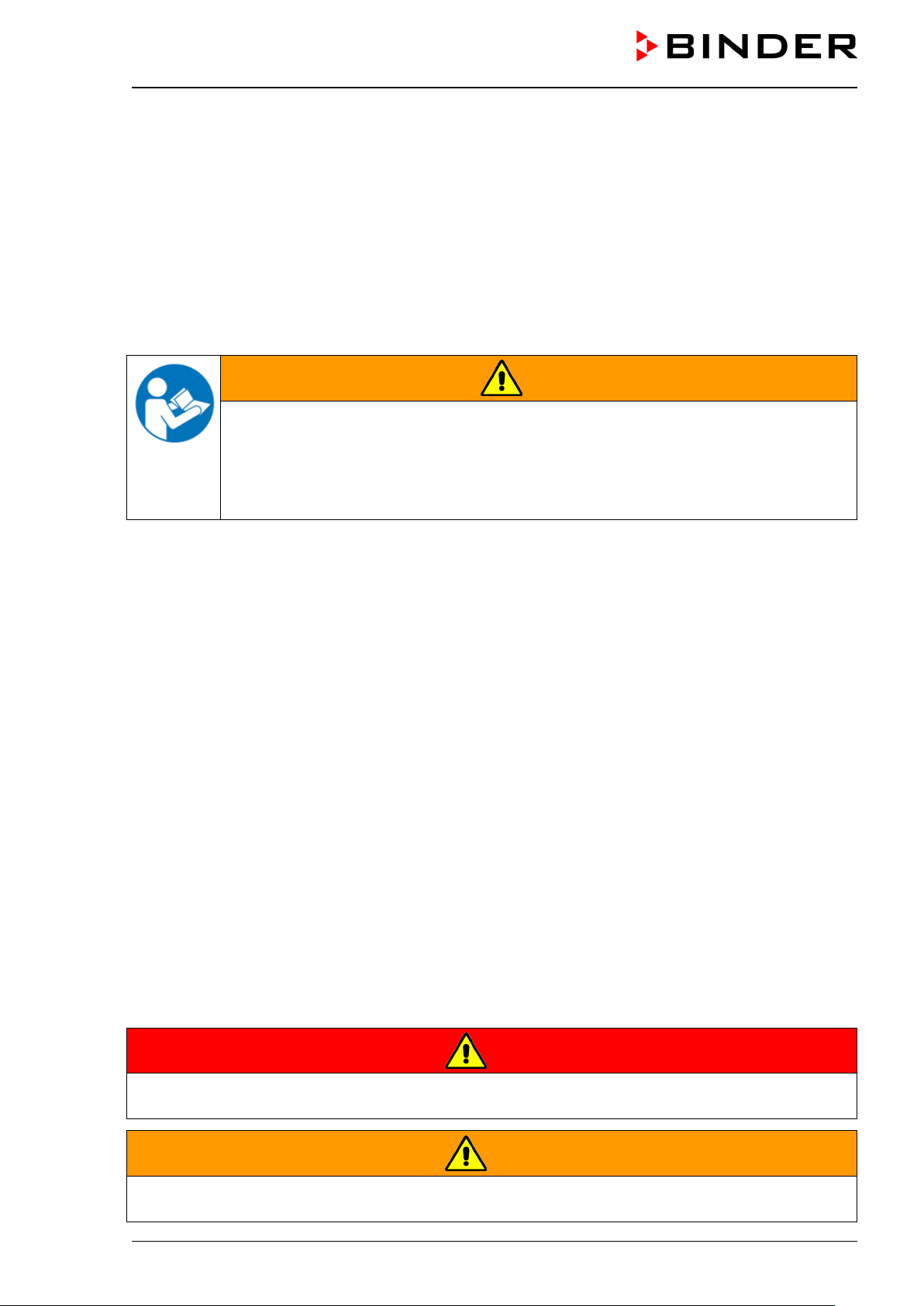
1.2.3 Pictograms
Warning signs
Electrical hazard
Hot surface
Explosive atmosphere
Stability hazard
Lifting hazard
Scalding hazard
High humidity
UV light hazard
Danger of frost
Risk of corrosion and /
or chemical burns
Harmful substances
Biohazard
Pollution Hazard
Mandatory action signs
Mandatory regulation
Read operating
instructions
Disconnect the power
plug
Lift with several persons
Lift with mechanical
assistance
Environment protection
Wear protective gloves
Wear safety goggles
KBF LQC (E5.3) 07/2014 page 10/114
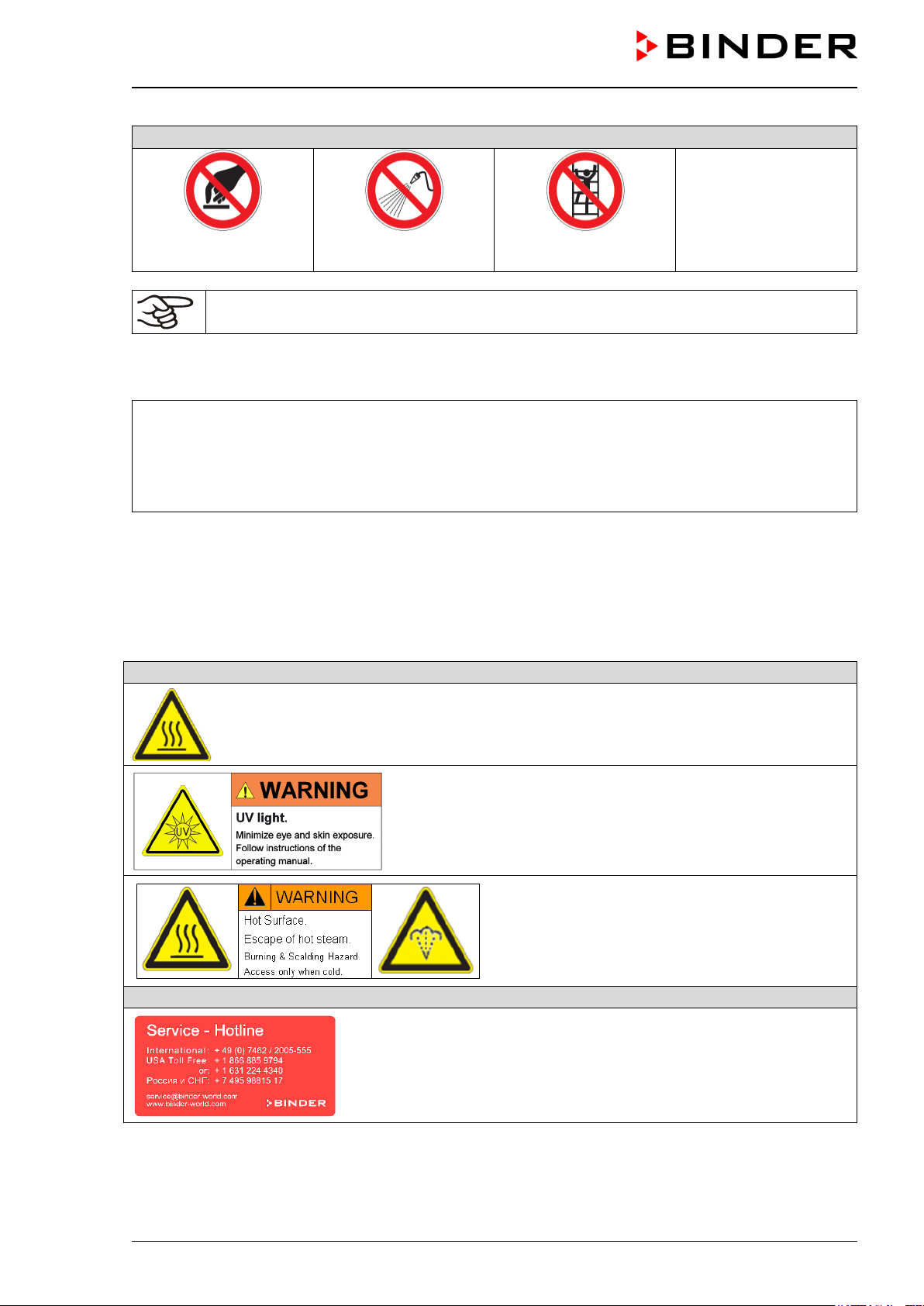
Prohibition signs
Do NOT touch
Do NOT spray with
water
Do NOT climb
Information to be observed in order to ensure optimum function of the product.
1.2.4 Word message panel structure
Type / cause of hazard.
Possible consequences.
∅ Instruction how to avoid the hazard: prohibition
Instruction how to avoid the hazard: mandatory action.
Observe all other notes and information not necessarily emphasized in the same way, in order to avoid
disruptions that could result in direct or indirect injury or property damage.
1.3 Localization / position of safety labels on the unit
The following labels are located on the unit:
Pictograms (warning signs)
Hot surface (on outer door)
UV light hazard (on outer door)
Burning and scalding hazard (on unit rear)
Service label
KBF LQC (E5.3) 07/2014 page 11/114
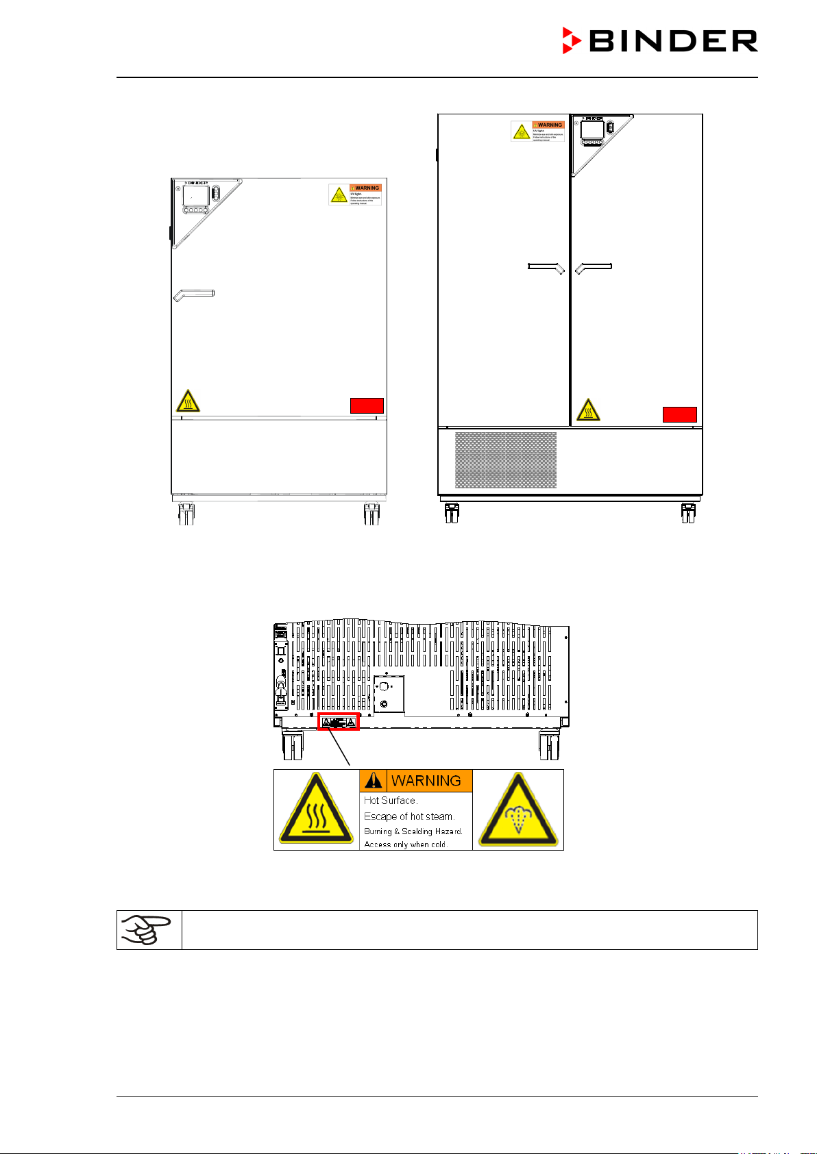
Figure 1: Position of labels on the unit front KBF LQC
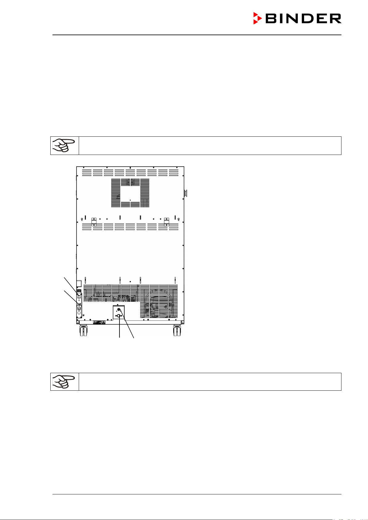
Figure 2: Position of labels on the unit rear
Keep safety labels complete and legible.
Replace safety labels that are no longer legible. Contact BINDER Service for these replacements.

KBF LQC (E5.3) 07/2014 page 12/114
1.4 Type plate
Position of type plate: left unit side (seen from front), at the bottom right-hand.
Figure 3: Type plate (example of KBF LQC 240 regular unit 9020-0277)
Indications of the type plate (example)
Information
BINDER
Manufacturer: BINDER GmbH
KBF LQC 240
Model designation
Constant climate chamber
Device name
Serial No.
00-00000
Serial no. of the unit
Built
2014
Year of construction
Nominal temperature
70 °C / 158°F
Nominal temperature
Enclosure protection
IP 20
IP type of protection acc. to EN 60529
Temp. safety device
DIN 12880
Temperature safety device acc. to standard DIN 12880
Class
3.1
Class of temperature safety device
Art. No.
9020-0277
Art. no. of the unit
Project No.
---
Optional: Special application acc. to project no.
2,40 kW
Nominal power
200-240 V 1 N ~
Nominal voltage (+/-10%), phase indication
10,9 A
Nominal current
50 Hz
Power frequency
Max. operating pressure 15 bar Max operating pressure in the refrigerating system
(15 bar / 218 PSI)
R 134 a - 0,575 kg
Refrigerant type and filling weight
Contains fluorinated greenhouse gases covered by the Kyoto Protocol
Symbol on the type plate
Information
CE conformity marking
Electrical and electronic equipment manufactured / placed
on the market in the EC after 13 August 2005 and be dis-
posed of in separate collection according to the directive
2002/96/EC on waste electrical and electronic equipment
(WEEE).
The equipment is certified in the GOST R certification sys-
tem of GOSTSTANDARD Russia.
Nominal temperature
70 °C
2,40 kW
Max. operating pressure 15 bar
158°F
200-240 V 1 N ~
R 134 A - 0,575 kg
Enclosure protection
Temp. safety device
IP 20
DIN 12880
10,9 A
50 Hz
Contains fluorinated greenhouse gases
covered by the Kyoto Protocol
Class
3.1
Art. No.
9020-0277
US PATS 4585923 / 5222612 / 5309981
Project No.
Built
2014
5405194 / 5601143 / 5773287 / 6079403
Constant climate chamber
D 78532 Tuttlingen / Germany
Tel. + 49 (0) 7462/ 2005-0
Internet: www.binder-world.com
KBF LQC 240 Serial No. 00-00000
E5.3 Made in Germany
KBF LQC (E5.3) 07/2014 page 13/114
1.5 General safety instructions on installing and operating the constant climate
chamber
With regard to operating the constant climate chamber KBF LQC and to the installation location, please
observe the guideline BGI/GUV-I 850-0 on safe working in laboratories (formerly BGR/GUV-R 120 or ZH
1/119 laboratory guidelines issued by the employers’ liability insurance association) (for Germany.
BINDER GmbH is only responsible for the safety features of the unit provided skilled electricians or quali-
fied personnel authorized by BINDER perform all maintenance and repair, and if components relating to
chamber safety are replaced in the event of failure with original spare parts.
To operate the unit, use only original BINDER accessories or accessories from third-party suppliers au-
thorized by BINDER. The user is responsible for any risk caused by using unauthorized accessories.
CAUTION
Danger of overheating.
Damage to the unit.
∅ Do NOT install the unit in unventilated recesses.
Ensure sufficient ventilation for dispersal of the heat.
Do not operate the constant climate chamber KBF LQC in hazardous locations.
DANGER
Explosion hazard.
Danger of death.
∅ Do NOT operate the unit in potentially explosive areas.
∅ KEEP explosive dust or air-solvent mixtures AWAY from the unit.
The constant climate chamber KBF LQC does not dispose of any measures of explosion protection.
DANGER
Explosion hazard.
Danger of death.
∅ Do NOT introduce any substance into the constant climate chamber which is combus-
tible or explosive at working temperature.
∅ NO explosive dust or air-solvent mixture in the inner chamber.
Any solvent contained in the charging material must not be explosive or inflammable. I.e., irrespective of
the solvent concentration in the steam room, NO explosive mixture with air must form. The temperature
inside the chamber must lie below the flash point or below the sublimation point of the charging material.
Familiarize yourself with the physical and chemical properties of the charging material, as well as the
contained moisture constituent and its behavior with the addition of heat energy and humidity.
Familiarize yourself with any potential health risks caused by the charging material, the contained mois-
ture constituent or by reaction products that may arise during the temperature process. Take adequate
measures to exclude such risks prior to putting the constant climate chamber into operation.
KBF LQC (E5.3) 07/2014 page 14/114
DANGER
Electrical hazard.
Danger of death.
∅ The unit must NOT become wet during operation or maintenance.
The constant climate chambers were produced in accordance with VDE regulations and were routinely
tested in accordance to VDE 0411-1 (IEC 61010-1).
During and shortly after operation, the temperature of the inner surfaces almost equals the set-point.
CAUTION
The glass doors, the glass door handles, the inner chamber, and the light cassettes
will become hot during operation.
Danger of burning.
∅ Do NOT touch the glass doors, the inner surfaces, the light cassettes or the charging
material during operation.
WARNING
Stability hazard.
Danger of injury.
Damage to the unit and the charging material.
Housing cover breakaway.
∅ Do NOT climb on the lower housing cover.
∅ Do NOT load the lower housing cover with heavy objects while the unit door is open.
KBF LQC (E5.3) 07/2014 page 15/114
1.6 Intended use
Constant climate chambers series KBF LQC are suitable for exact conditioning of harmless materials. A
mixture of any component of the charging material with air must NOT be explosive. The operating tem-
perature must lie below the flash point or below the sublimation point of the charging material.
Other applications are not approved.
Constant climate chambers series KBF LQC are not classified as medical devices as defined by
the Medical Device Directive 93/42/EEC.
Observing the instructions in this operating manual and conducting regular maintenance work
(chap. 18) is part of the intended use.
DANGER
Explosion hazard.
Danger of death.
∅ Do NOT introduce any substance combustible or explosive at working temperature into
the constant climate chamber.
∅ NO explosive dust or air-solvent mixture in the inner chamber.
The charging material shall not contain any corrosive ingredients that may damage the ma-
chine components made of stainless steel, aluminum, and copper. Such ingredients include in
particular acids and halides. Any corrosive damage caused by such ingredients is excluded
from liability by BINDER GmbH.
WARNING: If customer should use a BINDER chamber running in non-supervised continuous
operation, we strongly recommend in case of inclusion of irrecoverable specimen or samples
to split such specimen or samples and store them in at least two chambers, if this is feasible.
KBF LQC (E5.3) 07/2014 page 16/114
1.7 Resistance of the humidity sensor against harmful substances
The following list of harmful substances refers only to the humidity sensor and does not consider any
other materials incorporated in the unit or prohibited substances in relation to explosion protection.
Some gases - especially clean gases - do not have any influence on the humidity sensor. Others do have
only very small influence, whereas others may influence the sensor to a large extent.
• The following gases do not influence the sensor and the humidity measurement: Argon (Ar), carbon
dioxide (CO
2
),helium (He), hydrogen (H
2
), neon (Ne), nitrogen (N
2
), nitrous oxide (N
2
O), oxygen (O
2
)
• The following gases do not or only to a minor extent influence the sensor and the humidity measure-
ment: Butane (C
4
H
10
), ethane (C
2
H
6
), methane (CH
4
), natural gas propane (C
3
H
8
)
• The following gases do not or only to a minor extent influence the sensor and the humidity measure-
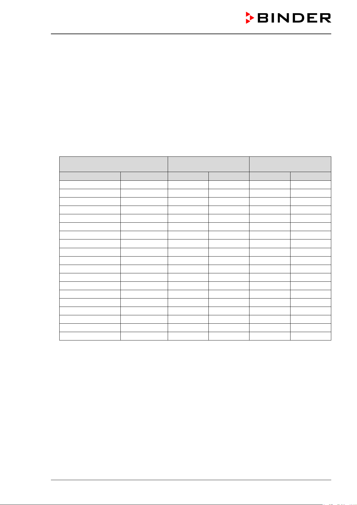
ment, provided that the indicated loads are not exceeded:
Maximum work place
threshold limit value
Tolerated concentration
with permanent load
Substance
Formula
ppm
mg/m
3
ppm
mg/m
3
Ammonia
NH
3
20
14
5500
4000
Acetone
CH
3
COCH
3
500
1200
3300
8000
Benzene
300
1200
150000
Chlorine
Cl
2
0.5
1.5
0.7
2
Acetic acid
CH
3
COOH
10
25
800
2000
Ethyl acetate
CH
3
COOC
2
H
5
400
1400
4000
15000
Ethanol
C
2
H
5
OH
500
960
3500
6000
Ethylene glycol
HOCH
2
CH
2
OH
10
26
1200
3000
Formaldehyde
HCHO
0.3
0.37
2400
3000
Isopropanol
(CH
3
)
2
CHOH
200
500
4800
12000
Methanol
CH
3
OH
200
260
3500
6000
Methyl ethyl ketone
C
2
H
5
COCH
3
200
590
3300
8000
Ozone
O
3
0.1
0.2
0.5
1
Hydrochloric acid
HCl
2
3
300
500
Hydrogen sulphide
H
2
S
10
15
350
500
Nitrogen oxides
NOx
5
9
5
9
Sulphur dioxide
SO
2
5
13
5
13
Toluol
C
6
H
5
CH
3
100
380
1300
5000
Xylene
C
6
H
4
(CH
3
)
2
100
440
1300
5000
These values are to be considered as approximate values. The sensor resistance largely depends on
the temperature and humidity conditions during the time of exposition to harmful substances. Avoid
simultaneous condensation. Tolerated error of measurement: ± 2 %r.H. The maximum work place
threshold limit value is the value which can be regarded harmless for humans.
• Vapors of oil and fat are dangerous for the sensor because they may condensate at the sensor and
thus prevent its function (insulating layer). For similar reasons it is also not possible to measure smoke
gases.

KBF LQC (E5.3) 07/2014 page 17/114
2. Unit description
The constant climate chambers KBF LQC are equipped with a multifunctional microprocessor display
controller with 2-channel technology for temperature and humidity and a digital display accurate to one-
tenth of a degree resp. 0.1% r.H. With its comprehensive program control functions, the MB1 display
program controller permits the high precision course of temperature and humidity cycles as well as con-
trolled exposition of the samples up to defined dose values.
With its microprocessor controlled humidifying and dehumidifying system the KBF LQC is a high-
precision climatic chamber. It completely meets the requirements of the stipulated stability and durability
test for pharmaceutical products:
• Stability tests acc. to ICH guideline CPMP/ICH/2736/99 (Q1A)
• Photostability tests acc. to ICH guideline CPMP/ICH/279/95 (Q1B)
Furthermore, it permits simulating exactly and over long periods constant conditions for other applications
such as sample conditioning for material testing of paper, textiles, plastics, building materials, etc.
The APT.line™ preheating chamber system guarantees high level of spatial and time-based temperature
precision, thanks to the direct and distributed air circulation into the interior. The fan supports exact at-
tainment and maintenance of the desired temperature accuracy.
The function Light Quantum Control permits integration of UV intensity and luminous intensity inside the
usable volume. The optical sensors used according to the ICH guideline for stability and durability tests of
pharmaceutical products Q1B. Sensor measurement is to a great extent directionally independent, dif-
fused light is also weighted. The function Light Quantum Control permits apart from displaying the actual
values of UVA and the visible spectral range cumulative measurement of the light doses In Manual Mode
target dose values of UVA and the visible spectral range can be entered. When they are reached, the
UVA and cool white fluorescent tubes are automatically turned off and notifying and alarm messages are
released.
A resistance humidifying system humidifies the air. For this purpose, use deionized (demineralized) wa-
ter. The option BINDER Pure Aqua Service permits using the chamber with any degree of water hard-
ness.
The inner chamber, the pre-heating chamber and the inside of the doors are all made of stainless steel
V2A (German material no. 1.4301, US equivalent AISI 304). The housing is RAL 7035 powder-coated. All
corners and edges are also completely coated.
All unit functions are easy and comfortable to use thanks to their clear arrangement. Major features are
easy cleaning of all unit parts and avoidance of undesired contamination.
The efficient program controller is regularly equipped with a multitude of operating functions, additional
recorder and alarm functions. Programming of test cycles is easily done via the modern MB1 color-
display controller and is also possible directly from the computer via Intranet in connection with the com-
munication software APT-COM™ 3 DataControlSystem (option, chap. 17.1).
The constant climate chamber KBF LQC is regularly equipped with an Ethernet serial interface for com-
puter communication. As a system solution BINDER offers the combination of the constant climate
chamber with ICH compliant illumination and the function Light Quantum Control with the GLP/GMP
compliant software APT-COM™ 3. This comfortable communication software from BINDER permits net-
working up to 30 units and connecting them to a PC for controlling and programming, as well as record-
ing and representing temperature and humidity data. For further options, see chap.21.5.
The KBF LQC is equipped with four castors. Both front castors can be locked by brakes.
The chambers can be operated in a temperature range from 0 °C / 32°F up to 70 °C / 158°F (without light
cassettes) / from 10 °C / 50°F up to 60 °C / 140°F (with illumination) and in a humidity range of 10% r.H.
to 80% r.H. When at least one light sensor is plugged-in, the maximum temperature is automatically lim-
ited to 60 °C.
For the control ranges of temperature and humidity, see diagrams (chap. 13).
KBF LQC (E5.3) 07/2014 page 18/114
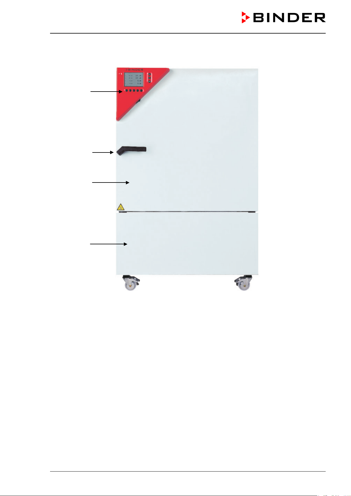
2.1 Unit overview
Figure 4: KBF LQC 240
(A) Instrument panel
(B) Door handle
(C) Outer door
(D) Refrigerating machine and humidity generation module
(A)
(B)
(C)
(D)
KBF LQC (E5.3) 07/2014 page 19/114
2.2 Lateral control panel, right side
(3)
(4)
(5)
(6)
(9)
(7)
(8)
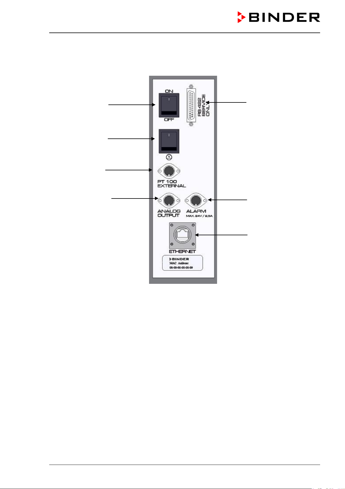
Figure 5: Lateral control panel KBF LQC at the right side of the humidity module
with options analog outputs, alarm contact, and additional Pt100 sensor
(3) Main power switch ON/OFF
(4) Humidity switch ON/OFF
(5) DIN-socket additional Pt100 temperature sensor (option)
(6) DIN-socket analog outputs (option)
(7) DIN-socket alarm contact (option)
(8) Ethernet interface for computer communication with indication of the MAC address
(9) RS422 interface (for service purpose only)

KBF LQC (E5.3) 07/2014 page 20/114
2.3 Lateral control panel, left side
(10)
(11)
(12)
(14)
(15)
Figure 6: Lateral control panel KBF LQC at the left side of the humidity module
with option temperature safety device class 3.3
(10) Switch for ICH compliant illumination cool white
(11) Switch for ICH compliant illumination BINDER Q1B Synergy Light (UVA + cool white)
(12) Key switch to turn on and off and to reset the integrator
(13) Not used
(14) Temperature safety device class 3.1 (part of option safety device class 3.3)
(15) Temperature safety device class 3.2 (part of option safety device class 3.3)

KBF LQC (E5.3) 07/2014 page 21/114
2.4 Instrument panel
Figure 7: Triangle instrument panel KBF LQC
(1) MB1 microprocessor program controller with 2-channel technology for temperature and humidity,
display of the actual light values and cumulative measurement of the light doses of UVA and the
visible spectral range.
(2) Rocker switch to display either the actual light values (switch in position ON – green mark visible)
or the integrated light values
3. Completeness of delivery, transportation, storage, and installa-
tion
3.1 Unpacking, and checking equipment and completeness of delivery
After unpacking, please check the unit and its optional accessories, if any, based on the delivery note for
completeness and for transportation damage. Inform the carrier immediately if transportation damage has
occurred.
The final tests of the manufacturer may have caused traces of the shelves on the inner surfaces. This
has no impact on the function and performance of the unit.
Please remove any transportation protection devices and adhesives in/on the unit and on the doors and
take out the operating manuals and accessory equipment.
(1)
(2)
KBF LQC (E5.3) 07/2014 page 22/114
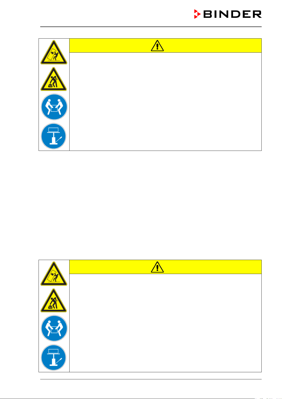
CAUTION
Sliding or tilting of the unit.
Damage to the unit.
Risk of injury by lifting heavy loads.
∅ Do NOT lift or transport the unit using the door handle, the door or the lower housing.
Lift units size 240 from the pallet at the four lower corners with the aid of six people or
with a fork lifter. Set the fork lifter only from the front or rear in the middle of the unit.
Lift units size 720 from the pallet using technical devices (fork lifter). Set the fork lifter
only from the front or rear in the middle of the unit.
∅ Do NOT set the fork lifter from the unit side.
If you need to return the unit, please use the original packing and observe the guidelines for safe lifting
and transportation (chap. 3.2).
For disposal of the transport packing, see chap. 19.1.
Note on second-hand units (Ex-Demo-Units):
Second-hand units are units that have been used for a short time for tests or exhibitions. They are thor-
oughly tested before resale. BINDER ensures that the chamber is technically sound and will work flaw-
lessly.
Second-hand units are marked with a sticker on the unit door. Please remove the sticker before commis-
sioning the unit.
3.2 Guidelines for safe lifting and transportation
The front castors of the KBF LQC can be blocked by brakes. Please move the units with castors only
when empty and on an even surface, otherwise the castors may be damaged. After operation please
observe the guidelines for temporarily decommissioning the unit (chap. 19.2).
CAUTION
Sliding or tilting of the unit.
Damage to the unit.
Risk of injury by lifting heavy loads.
Transport the unit only in its original packaging.
Secure the constant climate chamber with transport straps for transport.
∅ Do NOT lift or transport the unit using the door handle, the door or the lower housing.
Lift units size 240 at the four lower corners with the aid of 6 people or with a fork lifter.
Set the fork lifter only from the front or rear in the middle of the unit.
Lift units size 720 using technical devices (fork lifter). Set the fork lifter only from the
front or rear in the middle of the unit.
∅ Do NOT set the fork lifter from the unit side.
KBF LQC (E5.3) 07/2014 page 23/114
You can order transport packing for transportation purposes from BINDER service.
Permissible ambient temperature range during transport:
• If the steam humidifying system has NOT been emptied: +3 °C / 37.4°F to +60 °C / 140°F.
• After BINDER Service has emptied the steam humidifying system: -10 °C / 14°F to +60 °C / 140°F.
With temperatures below +3 °C / 37.4°F, water must be completely removed from the humidifying sys-
tem.
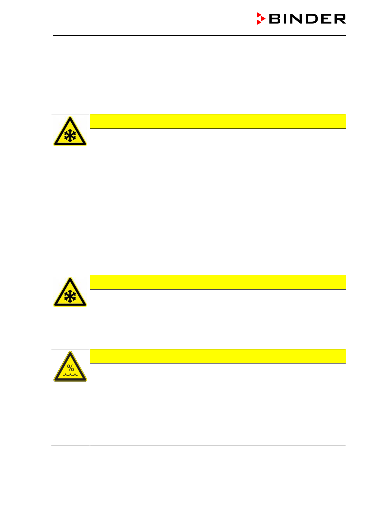
CAUTION
Transport below +3 °C / 37.4°F with filled steam humidifying system.
Freezing in the steam generator.
Damage to the unit.
Contact BINDER Service before any transportation below +3 °C / 37.4°F.
3.3 Storage
Intermediate storage of the unit is possible in a closed and dry room. Observe the guidelines for tempo-
rary decommissioning (chap. 19.2).
Permissible ambient temperature range during storage:
• If the steam humidifying system has NOT been emptied: +3 °C / 37.4°F to +60 °C / 140°F.
• After BINDER Service has emptied the steam humidifying system: -10 °C / 14°F to +60 °C / 140°F
With temperatures below +3 °C / 37.4°F, water must be completely removed from the humidifying sys-
tem.
CAUTION
Storage below +3 °C / 37.4°F with filled steam humidifying system.
Freezing in the steam generator.
Damage to the unit.
Contact BINDER Service before any transportation below +3 °C / 37.4°F.
Permissible ambient humidity: max. 70 % r.H., non-condensing
CAUTION
Condensation by excess humidity.
Danger of corrosion on the housing after operating at humidity values > 70 % r.H.
for a long period.
Dry the appliance completely before shut-down:
• Set the humidity to 0 % r.H. and turn on the humidity switch (4).
• Set the temperature set point to 60 °C / 140°F for approx. 2 hours (Manual mode).
• Only then, shut down the unit at the main power switch
(3) and close the tap of the
water supply.
When after storage in a cold location you transfer the unit to its warmer installation site, condensation
may form. Before start-up, wait at least one hour until the chamber has attained ambient temperature and
is completely dry.
In case of a prolonged temporal decommissioning: Leave the unit door open or remove the access port
plugs.
KBF LQC (E5.3) 07/2014 page 24/114
3.4 Location of installation and ambient conditions
Set up the constant climate chamber on a flat, even surface and in a well-ventilated, dry location and
align it using a spirit level. The site of installation must be capable of supporting the unit’s weight (see
technical data, chap. 21.4). The chambers are designed for setting up inside a building (indoor use).
CAUTION
Danger of overheating.
Damage to the unit.
∅ Do NOT set up unit in non-ventilated recesses.
Ensure sufficient ventilation for dispersal of the heat.
• Permissible ambient temperature range during operation: +18 °C / 64.4°F to +32 °C / 89.6°F. At
elevated ambient temperature values, fluctuations in temperature can occur.
The ambient temperature should not be substantially higher than the indicated ambient tem-
perature of +25 °C / 77°F to which the specified technical data relate. For other ambient condi-
tions, deviations from the indicated data are possible.
With each degree of ambient temperature >25 °C / 77°F, the refrigeration power decreases by
1.5 K.
• Permissible ambient humidity: 70 % r.H. max., non-condensing
When operating the chamber at temperature set-points below ambient temperature, high ambient humidi-
ty may lead to condensation on the unit.
• Installation height: max. 2000 m above sea level.
A water tap (1 bar to 10 bar) is necessary for the installation of the humidification system (chap. 4.3). If no
suitable house water connection is available, you can manually supply water by filling the freshwater can
(option, chap. 17.9).
To avoid any possible water damage, provide a floor drain at the location of the device. Select
a suitable installation site to avoid any consequential damage by splashing water.
When placing several units of the same size side by side, maintain a minimum distance of 250 mm be-
tween each unit. Wall distances: rear 100 mm, sides 160 mm. Spacing above the unit of at least 100 mm
must also be accounted for.
CAUTION
Danger by stacking.
Damage to the units.
∅ Do NOT place constant climate chambers on top of each other.
To completely separate the unit from the power supply, you must disconnect the power plug. Install the
unit in a way that the power plug is easily accessible and can be easily pulled in case of danger.
With an increased amount of dust in the ambient air, clean the condenser fan (by suction or blowing)
several times a year.
Avoid any conductive dust in the ambiance according to the unit layout complying with pollution degree 2
(IEC 61010-1).

KBF LQC (E5.3) 07/2014 page 25/114
Do not install or operate the constant climate chamber KBF LQC in potentially explosive areas.
DANGER
Explosion hazard.
Danger of death.
∅ Do NOT operate the unit in potentially explosive areas.
KEEP explosive dust or air-solvent mixtures AWAY from the vicinity of the unit.
Having turned off the unit, you must close the tap of the water supply. Install the unit in a way that the
freshwater supply is easily accessible.
4. Installation and connections
4.1 Spacers for rear wall distance
Please fix both spacers with the delivered screws at the unit rear. This serves to ensure the prescribed
minimum distance to the rear wall of 100 mm / 3.94 in.
Figure 8: Spacer for rear wall distance
Figure 9: Rear KBF LQC with mounted spacers
KBF LQC (E5.3) 07/2014 page 26/114
4.2 Wastewater connection
Fasten the wastewater hose to the waste-water connection “OUT” (17) on the rear of the unit (olive ∅ 14
mm). Observe the following points:
• You can use a part of the delivered water hose as a drainage hose. In case another hose is used, it
has to be permanently resistant against at least 95 °C / 203°F.
• Mount the wastewater hose with a maximum positive inclination of 1 m and a maximum total length of
3 m.
• Protect both ends of the drainage hose with two of the four delivered hose clamps.
Waste water is collected in an internal can with a volume of approx. 0.5 liters. It is pumped off
only when required, thus there is no continuous waste water flow.
(22)
(16)
(18) (17)
(16) Power cable
(17) Waste-water connection “OUT” with hose
olive for hose ½“
(18) Freshwater connection “IN”
with screw
thread ¾’’ for hose ½“, with union nut
(22) Socket for optional freshwater can (chap.
17.9.1)
Figure 10: Rear view KBF LQC with water connections
Protect the waste water supply at both sides with the delivered hose clamps.
KBF LQC (E5.3) 07/2014 page 27/114
4.3 Freshwater supply
Connect the waste water pipe before connecting the unit to a freshwater pipe or filling the
freshwater can (option, chap. 17.9).
You can supply the unit with freshwater via a water pipe or by manually filling a freshwater can (option,
chap. 17.9).
Water intake temperature NOT below +5 °C / 41°F and not exceeding 40 °C / 104°F.
CAUTION
Calcification of the humidifying system.
Damage to the unit.
Operate the unit with deionized (demineralized) water only.
Types of suitable water quality:
• Deionized water from a water treatment installation already existing at the customer's site. Conductivi-
ty from 1 µS /cm up to a maximum of 20 µS/cm. (Water, which is in equilibrium with the CO
2
in the air,
and has a conductivity below 1 µS/cm (ultrapure water), may cause acid corrosion due to its low pH.)
• Water treated by the optional water treatment system BINDER Pure Aqua Service (disposable sys-
tem). A reusable measuring equipment to assess the water quality is included (chap. 17.10).
BINDER GmbH is NOT responsible for the water quality at the customer.
Any problems and malfunctions that might arise following use of water of deviating quality is
excluded from liability by BINDER GmbH.
The warranty becomes void in the event of use of water of deviating quality.
4.3.1 Automatic fresh water supply via water pipe
An enclosure inside the unit contains the connection kit for freshwater and wastewater. Install the fresh-
water connection using either the enclosed water hose or another pressure-resistant one. For this re-
move the cover of the freshwater connection “IN” (18) on the rear of the unit. Protect both ends of the
hose with two of the four delivered hose clamps.
Before turning on the unit, check the connection for leaks. Water supply then automatically occurs via the
freshwater connection “IN” (18).
As the appliance only lets in water when required, there is no continuous water flow.
• Supply pressure 1 to 10 bar when connecting to a water pipe
• Water type: deionized (demineralized) water
• Water intake temperature NOT below +5 °C / 41°F and not exceeding 40 °C / 104°F.
• The water intake should be provided with a shut-off slide or water-tap.
•
For the water supply, fix the delivered adapter with hose olive on the thread at the rear of
the chamber.
• Protect the water supply at one side with the delivered hose clamp.

KBF LQC (E5.3) 07/2014 page 28/114
4.3.2 Manual fresh water supply via external freshwater can (option)
If no house water connection with suitable water is available, you can manually supply water by filling a
freshwater can (option, volume: 20 liters / 0.71 cu.ft.). You can fix the freshwater can at the rear of the
unit or place it next to the unit (chap. 17.9).
To guarantee humidification during 24 hours even at high humidity set-points with manual
water supply, we recommend filling the freshwater can (option) daily at the end of the day.
4.3.3 Connection kit for connection to the water main
A safety kit against flooding caused by burst water hoses is enclosed to the constant climate chamber. It
consists of:
• Hose burst protection device
• Hose nozzle with screwing
• 4 hose clamps
• 6m water hose, divisible for feed hose and the drain
Protection principle of hose burst protection:
Whenever a strong water flow of about 18 l / min. occurs, e.g. caused by a burst water hose, a valve au-
tomatically cuts off the water supply, what can be heard as a clicking noise. The water supply now re-
mains interrupted until its manual release.
Assembly:
Screw the hose burst protection device onto a water tap with a G¾ inch right turning thread connection.
The connection is self-sealing. Establish the connection between the safety kit and the chamber with a
part of the supplied hose. Protect both ends of the hose by the supplied hose clamps.
We recommend connecting the hose as the last step in order to avoid twisting the hose while screwing on
the safety kit.
Open the water tap slowly in order to avoid actuating the hose burst protection device.
Figure 11: Assembly of the connection kit
Release of the reflux protection device:
In case the burst protection device interrupted the water supply, find first the reason and remove it as far
as necessary. Close the water tap. Release the valve by a half left-turn of the upper knurled part. You can
hear the release of the valve as a clicking noise. Tighten the burst protection device against the water tap
by a right turn. Open the water tap slowly afterwards.
Maintenance of the assembly of the hose burst protection device:
Calcification can impair valve function. We recommend an annual inspection by a skilled plumper. The
plumper should demount the safety kit to check the valve by hand for function and calcification or block-
age.

KBF LQC (E5.3) 07/2014 page 29/114
CAUTION
Danger of calcification.
Impairment of valve function.
Have a plumber inspect the valve annually.
Remove calcifications by citric acid or acetic acid solutions.
Afterwards test the function and the tightness of the mounted unit
Check: Quickly open the water tap while there is no chamber connected – the valve has to cut off the
water flux without any delay.
4.3.4 Safety kit: Hose burst protection device with reflux protection device (available via
BINDER Individual)
For protection of the drinking water system, acc. to DIN 1988 part 4, and against flooding caused by burst
water hoses, a safety kit with reflux protection device is available.
Protection principles:
Whenever a strong water flow of about 18 l / min. occurs, e.g. caused by a burst water hose, a valve au-
tomatically cuts off the water supply, what can be heard as a clicking noise. The water supply now re-
mains interrupted until its manual release.
An eventual endangering of the drinking water system depends on the risk potential of the charging mate-
rial. Under unfavorable conditions (e.g. decreasing pressure inside the tap water system), drained off
charging material could be sucked out of the chamber via the steam generator into the tap water system
and therefore contaminate the drinking water. According to standard DIN 1988, part 4, the safety kit with
reflux protection device provides protection in case of short-term utilization of substances with low risk
potential. When using substances bearing a higher risk potential, install a pipe disconnector in order to
guarantee absolute protection. It is the user’s responsibility to prevent, according to national standards,
any reflux of contaminated water into the drinking water system.
Assembly:
The regularly delivered original parts – hose burst protection device, hose nozzle with screwing – are not
needed.
Screw the pre-mounted assembly of hose burst protection device and reflux protection device onto a
water tap with a G¾ inch right turning thread connection. The connection is self-sealing. Establish the
connection between the safety kit and the chamber with a part of the supplied hose. Protect both ends of
the hose by the supplied hose clamps.
We recommend connecting the hose as the last step in order to avoid twisting it while screwing on the
safety kit.
Open the water tap slowly in order to avoid actuating the hose burst protection device.
Figure 12: Assembly of the safety kit (hose burst protection device with reflux protection device)

KBF LQC (E5.3) 07/2014 page 30/114
Release of the reflux protection device:
In case the burst protection device interrupted the water supply, find first the reason and remove it as far
as necessary. Close the water tap. Release the valve by a half left-turn of the upper knurled part. You can
hear the release of the valve as a clicking noise. Tighten the burst protection device against the water tap
by a right turn. Open the water tap slowly afterwards.
Maintenance of the assembly of hose burst protection device with reflux protection device:
Calcification can impair the function of both valves. We recommend an annual inspection by a skilled
plumper. The plumper should demount the safety kit with reflux protection device to check both valves by
hand for function and calcification or blockage.
CAUTION
Danger of calcification.
Impairment of valve function.
Have a plumber inspect the two valves annually.
Remove calcifications by citric acid or acetic acid solutions.
Afterwards test the function and the tightness of the mounted unit.
Check: Quickly open the water tap while there is no chamber connected – the valve has to cut off the
water flux without any delay.
4.4 Electrical connection
The constant climate chamber comes with a fixed power connection cable that has a length of 1800 mm /
5.9 ft. The socket must also provide a protective conductor.
Model Power plug
Voltage
+/-10 %
Current type
Power
frequency
Unit fuse
KBF LQC 240
KBF LQC 720
Shock-proof
plug
200 V to 240 V 1N~ 50/60 Hz 16 Amp
Prior to connection and start-up, check the power supply voltage. Compare the values to the specified
data located on the unit’s type plate (left unit side, bottom right-hand, see chap. 1.4).
When connecting, please observe the regulations specified by the local electricity supply company and
as well the VDE directives (for Germany). We recommend the use of a residual current circuit breaker.
• Pollution degree (acc. to IEC 61010-1): 2
• Installation category (acc. to IEC 61010-1): II
CAUTION
Danger of incorrect power supply voltage.
Damage to the equipment.
Check the power supply voltage before connection and start-up.
Compare the power supply voltage with the data indicated on the type plate.
See also electrical data (chap. 21.4).
Loading...