


BD
Table of contents
 Loading...
Binder BD, BD023-230V, ED, ED240-230V, BD023UL-120V Operating Manual
...
Operating Manual
Translation of the original operating manual
BD / BD-UL (E2) – Incubators with natural convection
ED / ED-UL (E2) – Drying and heating ovens with natural convection
FD / FD-UL (E2) – Drying and heating ovens with forced convection
with microprocessor temperature controller
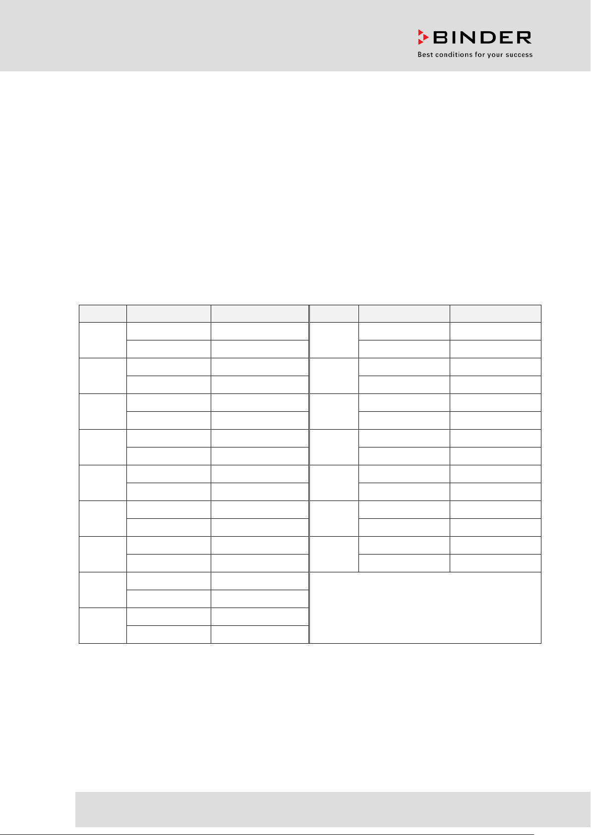
Modell Model version Art. No. Modell Model version Art. No.
BD 23
BD 53
BD 115
BD 240
BD400
BD720
ED 23
ED 53
BD023-230V 9010-0187
ED 240
BD023UL-120V 9010-0189 ED240UL-208V 9010-0167
BD053-230V 9010-0081
ED400
BD053UL-120V 9010-0179 ED400UL-208V 9010-0168
BD115-230V 9010-0088
ED720
BD115UL-120V 9010-0181 ED720UL-208V 9010-0169
BD240-230V 9010-0095
FD 23
BD240UL-120V 9010-0183 FD023UL-120V 9010-0196
BD400-230V 9010-0073
FD 53
BD400UL-120V 9010-0176 FD053UL-120V 9010-0128
BD720-230V 9010-0074
FD 115
BD720UL-120V 9010-0177 FD115UL-120V 9010-0129
ED023-230V 9010-0190/0191
FD 240
ED023UL-120V 9010-0192/0193 FD240UL-208V 9010-0130
ED053-230V 9010-0078/0079
ED053UL-120V 9010-0131/0132
ED240-230V 9010-0101
ED400-230V 9010-0075
ED720-230V 9010-0076
FD023-230V 9010-0194
FD053-230V 9010-0082
FD115-230V 9010-0102
FD240-230V 9010-0104
ED 115
ED115-230V 9010-0096/0097
ED115UL-120V 9010-0164/0165
BINDER GmbH
Address: Post office box 102, 78502 Tuttlingen, Germany Phone: +49 7462 2005 0
Fax: +49 7462 2005 100 Internet: http://www.b ind er -world.com
E-mail: info@binder-world.com Service Hotline: +49 7462 2005 555
Service Fax: +49 7462 2005 93 555 Service E-Mail: service@binder-world.com
Service Hotline USA: +1 866 885 9794 or +1 631 224 4340 x3
Service Hotline Asia Pacif ic: +852 390 705 04 or +852 390 705 03
Service Hotline Russia and CIS: +7 495 988 15 16
Issue 03/2019 Art. No. 7001-0026

Content
1. SAFETY .................................................................................................................. 4
1.1 Legal considerations ........................................................................................................................... 4
1.2 Structure of the safety instructions ...................................................................................................... 4
1.2.1 Signal word panel .......................................................................................................................... 4
1.2.2 Safety alert symbol ........................................................................................................................ 5
1.2.3 Pictograms ..................................................................................................................................... 5
1.2.4 Word message panel structure ...................................................................................................... 6
1.3 Localization / position of safety labels on the chamber ...................................................................... 6
1.4 Type plate............................................................................................................................................ 7
1.5 General safety instructions on installing and operating the chambers ............................................... 8
1.6 Intended use ..................................................................................................................................... 10
1.7 Operating instructions ....................................................................................................................... 11
1.8 Measures to prevent accidents ......................................................................................................... 11
2. CHAMBER DESCRIPTION .................................................................................. 12
2.1 Chamber overview ............................................................................................................................ 13
3. COMPLETENESS OF DELIVERY, TRANSPORTATION, STORAGE, AND
INSTALLATION .................................................................................................... 13
3.1 Unpacking, and checking equipment and completeness of delivery ................................................ 13
3.2 Guidelines for safe lifting and transportation ..................................................................................... 14
3.3 Storage .............................................................................................................................................. 14
3.4 Location of installation and ambient conditions ................................................................................ 15
4. INSTALLATION OF THE EQUIPMENT ............................................................... 16
4.1 Electrical connection ......................................................................................................................... 16
4.2 Connection to a suction plant (optional) ............................................................................................ 17
5. START UP ............................................................................................................ 17
5.1 Turning on the chamber .................................................................................................................... 17
5.2 Heating operation display.................................................................................................................. 17
5.3 Air change ......................................................................................................................................... 18
6. OPERATING THE CONTROLLER ....................................................................... 18
6.1 Display / entry of temperature set-point (without ramp function) ...................................................... 18
6.2 Display / entry of temperature set-point (with selected temperature ramp) ...................................... 19
6.3 Time functions: Continuous operation and Timer operation ............................................................. 20
6.3.1 Switching between “Continuous operation” and “Timer operation” ............................................. 21
6.3.2 Continuous operation ................................................................................................................... 21
6.3.3 Timer operation: Setting the tempering time ................................................................................ 22
6.4 User level settings ............................................................................................................................. 23
6.4.1 Temperature unit change between degrees Celsius °C and degrees Fahrenheit °F .................. 23
6.4.2 Entering a temperature ramp ....................................................................................................... 24
6.4.3 Chamber addressing .................................................................................................................... 24
6.5 General notes .................................................................................................................................... 25
7. TEMPERATURE SAFETY DEVICES ................................................................... 26
7.1 Temperature safety device class 2 (DIN 12880) ED, FD .................................................................. 26
7.2 Temperature safety device class 3.1 (DIN 12880) BD (option for ED, FD) ...................................... 27
BD / ED / FD (E2) 03/2019 page 2/68

8. OPTIONS .............................................................................................................. 29
8.1 Disconnectable audible over-temperature alarm (option) ................................................................. 29
8.2 APT-COM™ 4 Multi Management Software (option for BD and ED) ............................................... 29
8.3 Data logger kit (option) ...................................................................................................................... 29
8.4 Additional Pt100 temperature sensor (option for BD) ....................................................................... 30
8.5 Analog output for temperature (option) ............................................................................................. 30
8.6 Water protected internal socket (option for BD) ................................................................................ 31
9. MAINTENANCE, CLEANING, AND SERVICE .................................................... 32
9.1 Maintenance intervals, service .......................................................................................................... 32
9.2 Cleaning and decontamination ......................................................................................................... 32
9.2.1 Cleaning ....................................................................................................................................... 33
9.2.2 Decontamination .......................................................................................................................... 34
9.3 Sending the chamber back to BINDER GmbH ................................................................................. 35
10. DISPOSAL............................................................................................................ 36
10.1 Disposal of the transport packing ...................................................................................................... 36
10.2 Decommissioning .............................................................................................................................. 36
10.3 Disposal of the chamber in the Federal Republic of Germany ......................................................... 36
10.4 Disposal of the chamber in the member states of the EU except for the Federal Republic of
Germany............................................................................................................................................ 37
10.5 Disposal of the chamber in non-member states of the EU ............................................................... 38
11. TROUBLESHOOTING ......................................................................................... 39
12. TECHNICAL DESCRIPTION ................................................................................ 40
12.1 Factory calibration and adjustment ................................................................................................... 40
12.2 Definition of usable volume ............................................................................................................... 40
12.3 Over current protection ..................................................................................................................... 40
12.4 BD technical data .............................................................................................................................. 41
12.5 ED technical data .............................................................................................................................. 42
12.6 FD technical data .............................................................................................................................. 44
12.7 Equipment and options BD (extract) ................................................................................................. 47
12.8 Equipment and options ED (extract) ................................................................................................. 48
12.9 Equipment and options FD (extract) ................................................................................................. 49
12.10 Accessories and spare parts (extract) .............................................................................................. 50
13. CERTIFICATES AND DECLARATIONS OF CONFORMITY ............................... 51
13.1 EU Declaration of Conformity for BD ................................................................................................ 51
13.2 EU Declaration of Conformity for ED ................................................................................................ 54
13.3 EU Declaration of Conformity for FD ................................................................................................ 57
13.4 Certificate for the GS mark of conformity of the “Deutsche Gesetzliche Unfallversicherung e.V.“
(German Social Accident Insurance) DGUV ..................................................................................... 60
14. PRODUCT REGISTRATION ................................................................................ 62
15. CONTAMINATION CLEARANCE CERTIFICATE ............................................... 63
15.1 For chambers located outside the USA and Canada ....................................................................... 63
15.2 For chambers located in the USA and Canada ................................................................................ 66
BD / ED / FD (E2) 03/2019 page 3/68
Dear customer,
For the correct operation of the chambers, it is im portant that you read this operat ing manual com pletely
and carefully and observe all instructions as indicated. Failure to read, understand and follow the
instructions may result in personal injury. It can also lead to damage to the chamber and/or poor
equipment performance.
Understanding and obser ving the instructions in this operat ing manual are prerequisites for ha zard-free
use and safety during operation and maintenance. In no event shall BINDER be held liable for any
damages, direct or incidental arising out of or related to the use of this manual.
1. Safety
This operating manual is part of the components of delivery. Always keep it handy for reference. The
device should only be operated b y laboratory personnel especially trained f or this purpose and familiar
with all precautionar y measures require d for working i n a laborator y. Observe th e national regul ations on
minimum age of laborator y personn el T o avoid inj uries and dam age obser ve the saf et y instructions of the
operating manual.
WARNING
Failure to observe the safety instructions.
Serious injuries and chamber damage.
Observe the safety instructions in this operating manual
Carefully read the complete operating instructions of the chamber.
1.1 Legal considerations
This operating m anual is for informational purposes only. It contains information for ins talling, start-up,
operation and mainte nance of the product. Note: the contents and the pr oduct described are subjec t to
change without notice.
Understanding and obser ving the instructions in this operat ing manual are prerequisites for ha zard-free
use and safety during operation and maintenance. In no event shall BINDER be held liable for any
damages, direct or incidental arising out of or related to the use of this manual.
This operating manual can not cover all conce ivable applications . If you would like add itional inform ation,
or if special problem s arise that are not suff iciently addressed in th is manual, please ask your dealer or
contact us directly by phone at the number located on page one of this manual
Furthermore, we emphasize that the contents of this operating manual are not part of an earlier or
existing agreement, description, or legal relationship, nor do they modify such a relationship. All
obligations on the part of BINDER derive from the respective purchas e contract, which a lso contains the
entire and exclusivel y valid statement of warrant y administration. The statem ents in this manual neither
augment nor restrict the contractual warranty provisions.
1.2 Structure of the safety instructions
In this operating manual, the following safety definitions and symbols indicate dangerous situations
following the harmonization of ISO 3864-2 and ANSI Z535.6.
1.2.1 Signal word panel
Depending on the probability of serious consequences, potential dangers are identified with a signal
word, the corresponding safety color, and if appropriate, the safety alert symbol.
DANGER
Indicates an imminently hazardous situation that, if not avoided, will result in death or serious
(irreversible) injury.
BD / ED / FD (E2) 03/2019 page 4/68
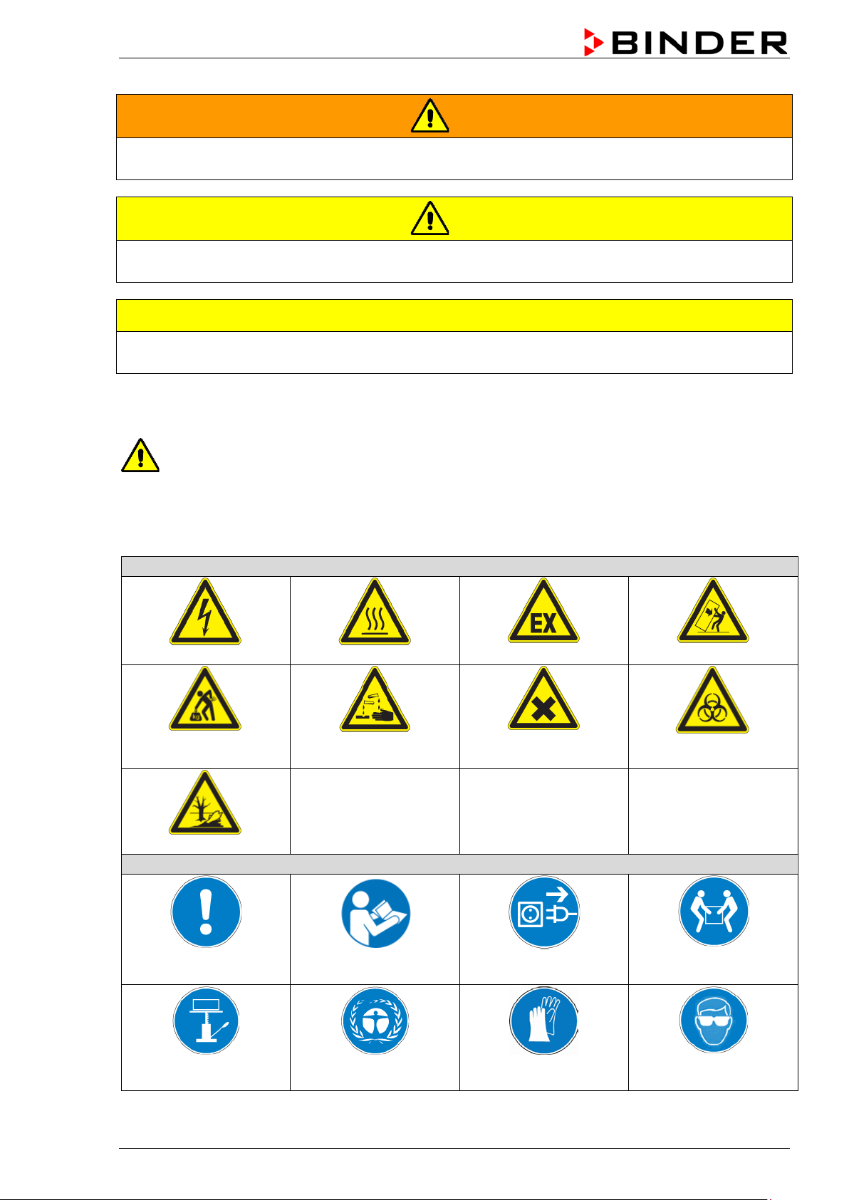
Warning signs
Electrical hazard
Hot surface
chemical burns
Pollution Hazard
Mandatory action signs
instructions
plug
assistance
WARNING
Indicates a potentially hazardous situation which, if not avoided, could result in death or serious
(irreversible) injury
CAUTION
Indicates a potentially hazardous situation which, if not avoided, may result in moderate or minor
(reversible) injury
CAUTION
Indicates a potentially hazardous situation which, if not avoided, may result in damage to the product
and/or its functions or of a property in its proximity.
1.2.2 Safety alert symbol
Use of the safety alert symbol indicates a risk of injury.
Observe all measures that are marked with the safety alert symbol in order to avoid death or
injury.
1.2.3 Pictograms
Lifting hazard
Mandatory regulation
Risk of corrosion and / or
Read operating
Explosive atmosphere
Harmful substances
Disconnect the power
Stability hazard
Biohazard
Lift with several persons
Lift with mechanical
BD / ED / FD (E2) 03/2019 page 5/68
Environment protection Wear protective gloves
Wear safety goggles
Prohibition signs
water
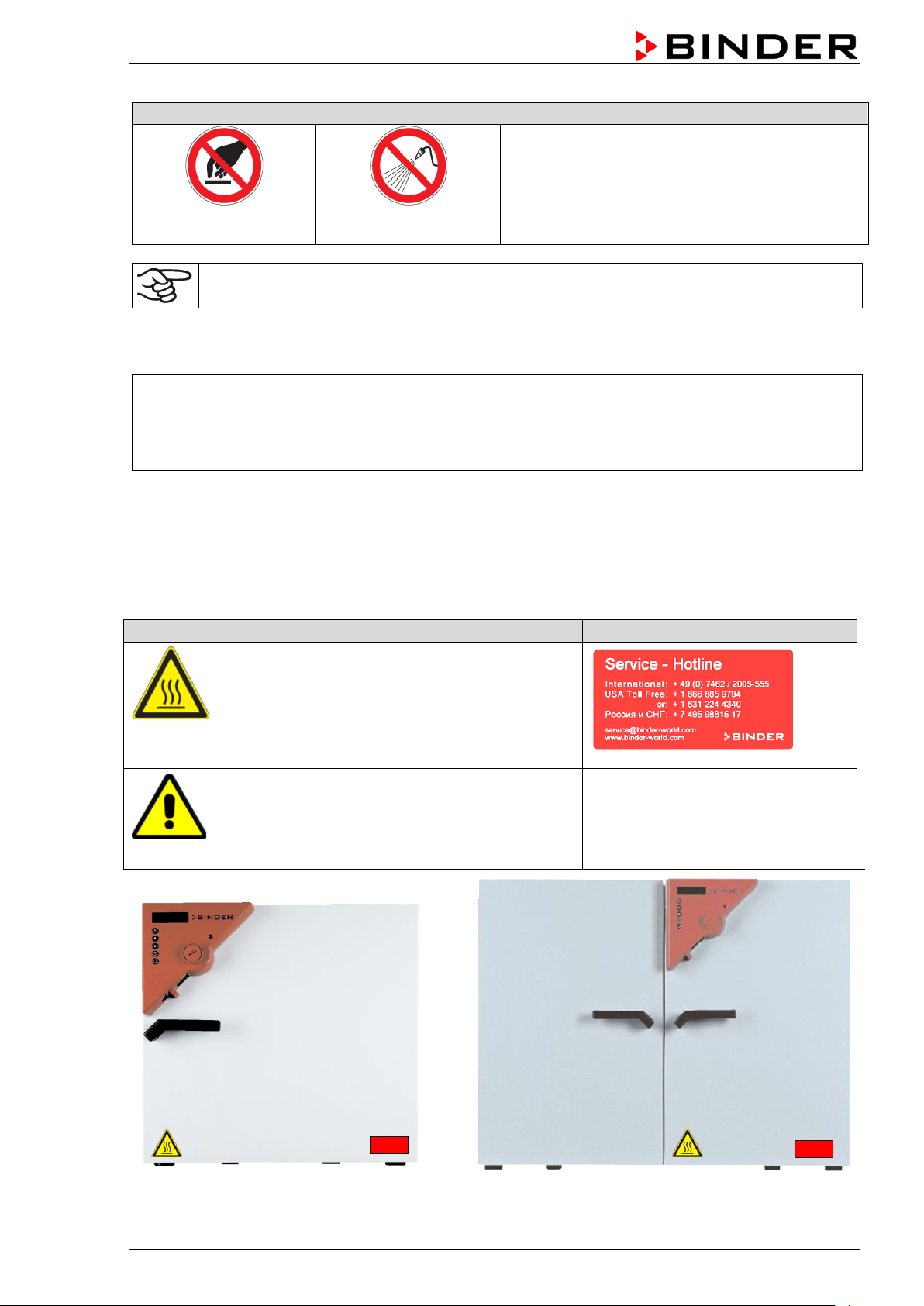
Pictograms (Warning signs)
Service label
Hot surface
Do NOT touch
Do NOT spray with
Information to be observed in order to ensure optimum function of the product.
1.2.4 Word message panel structure
Type / cause of hazard.
Possible consequences.
∅ Instruction how to avoid the hazard: prohibition.
Instruction how to avoid the hazard: mandatory action.
Observe all other notes and inf ormation not necessarily emphasi zed in the same way, in order to avoid
disruptions that could result in direct or indirect injury or property damage.
1.3 Localization / position of safety labels on the chamber
The following labels are located on the chamber:
• ED, FD: outer chamber door
• BD: inner glass door next to the glass door
handle
• On chamber rear next to the exhaust duct
Read operating manual
• UL chambers: outer chamber door
• BD with optional interior socket: below the
interior socket
BD / ED / FD (E2) 03/2019 page 6/68
Figure 1: Position of labels on the chamber on the front (example: ED, FD)
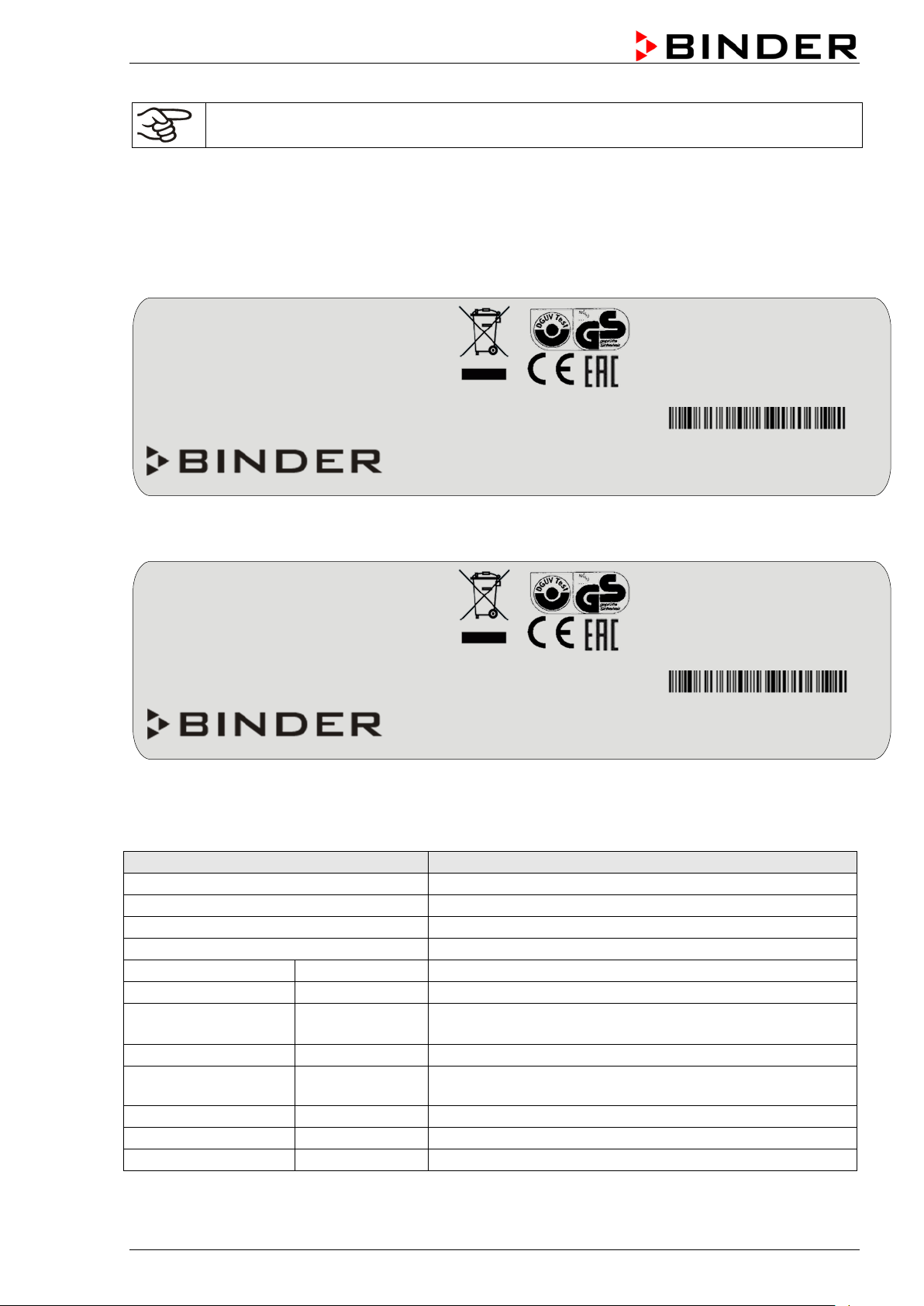
Indications of the type plate (example)
Information
BINDER
Manufacturer: BINDER GmbH
FD 115
Model designation
Incubator
Device name: Incubator
Drying and heating oven
Device name: Drying and heating oven
Serial No.
000000000000
Serial No.
Built
2019
Year of construction
100 °C
212 °F
IP protection
20
IP type of protection acc. to EN 60529
Class
3.1
Class of temperature safety device
Art. No.
9110-0081
Art. no. of the chamber
Project No.
---
Optional: Special application acc. to project no.
Nominal temp.
300 °C
1,60 kW / 7,0 A
572 °F
230 V / 50 Hz
IP protection
20
230 V / 60 Hz
Safety device
DIN 12880
1 N ~
Class
2.0
Art. No.
9010-0102
Project No.
Built
2019
Drying and heating oven
BINDER GmbH
www.binder-world.com
FD 115
E2
Serial No. 00000000000000
Nominal temp.
100 °C
0,40 kW / 1,8 A
With option internal socket:
212 °F
230 V / 50 Hz
Nominal power: 0,90 kW
IP protection
20
230 V / 60 Hz
Safety device
DIN 12880
1 N ~
Class
3.1
Art. No.
9010-0081
Built
2019
Incubator
BINDER GmbH
www.binder-world.com
BD 53
E2
Serial No. 00000000000000
Keep safety labels complete and legible.
Replace safety labels that are no longer legible. Contact BINDER Service for these replacements.
1.4 Type plate
The type plate is locat ed on the left-hand side of the chamber (size 23) or on th e chamber front behind
the door, bottom left-hand.
Im Mittleren Ösch 5
78532 Tuttlingen / Germany
Figure 2: Type plate (example: FD 115 regular chamber)
Made in Germany
Project No.
Im Mittleren Ösch 5
78532 Tuttlingen / Germany
Made in Germany
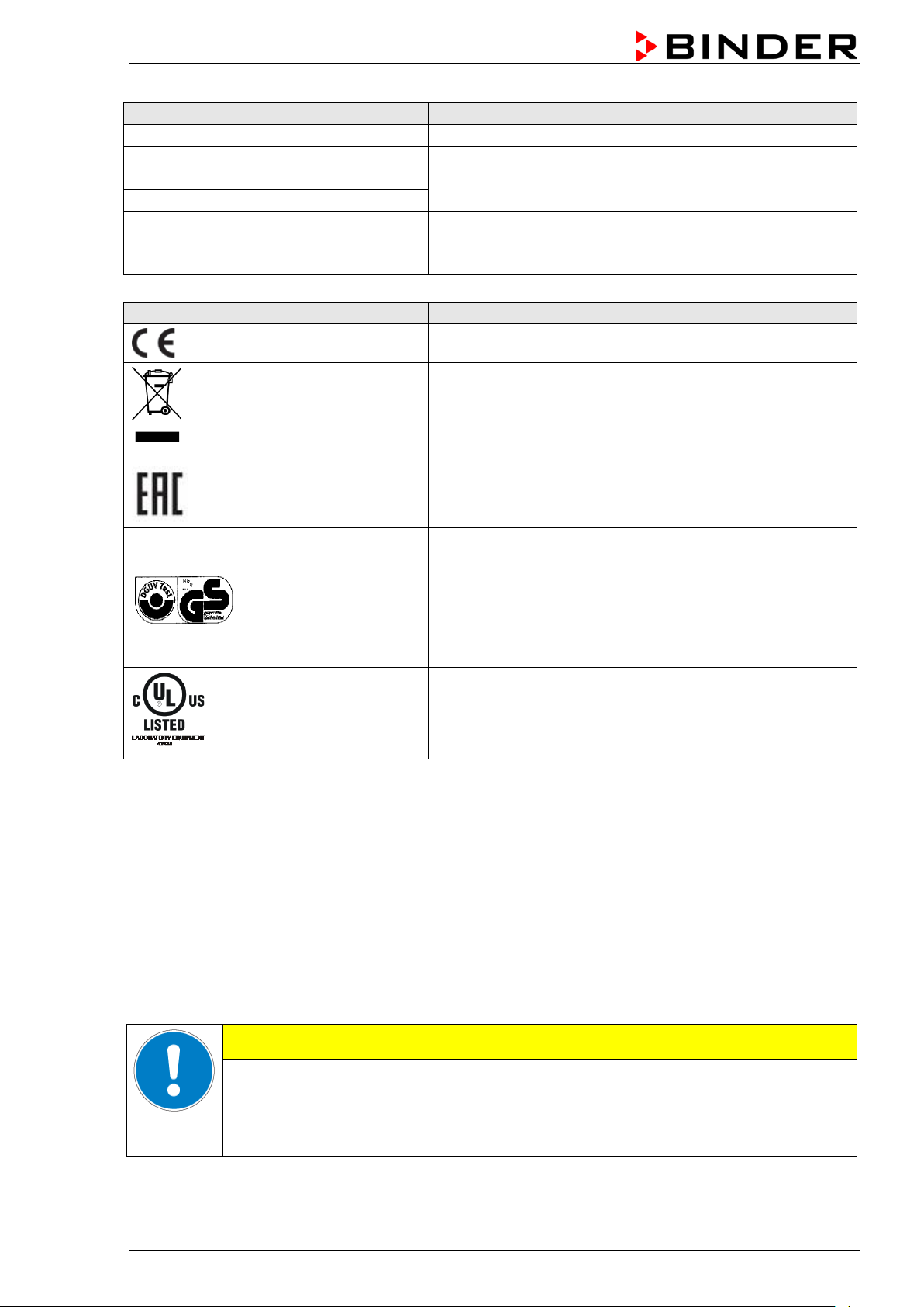
Figure 3: Type plate (example: BD 53 optional chamber)
Nominal temperature
Temp. safety device DIN 12880
BD / ED / FD (E2) 03/2019 page 7/68
Nominal temperature
Temperature safety device acc. to standard DIN
12880:2007
Indications of the type plate (example)
Information
0,40 kW
Nominal power
1,8 A
Nominal current
230 V / 50 Hz
230 V / 60 Hz
1 N ~
Current type
With option internal socket:
Nominal power: 0,90 kW
Symbol on the type plate
Information
Nominal voltage +/-10% at the indicated power frequency
With option internal socket: increased total nominal power
CE conformity marking
Electrical and electronic equipment manufactured / placed
on the market in the EU after 13 August 2005 and to be
disposed of in a separate collection according to directive
2012/19/EU on waste electrical and electronic equipment
(WEEE).
The chamber is certified according to Customs Union
Technical Regulation (CU TR) for the Eurasian Economic
Union (Russia, Belarus, Armenia, Kazakhstan Kyrgyzstan).
GS mark of conformity of the “Deutsche Gesetzliche
Unfallversicherung e.V. (DGUV), Prüf- und
Zertifizierungsstelle Nahrungsmittel und Verpackung im
DGUV Test“ (German Social Accident Insurance (DGUV),
Testing and Certification Body for Foodstuffs and
Packaging Industry in DGUV Test).
Not valid for UL chambers
®
(UL chamber only)
The chamber is certified by Underwriters Laboratories Inc.
according to the following standards:
st
UL 61010A-1, 1
Edition, UL 61010A-2-10, 1st Edition
CSA C22.2 No. 1010.1-92, IEC 1010-2-10
1.5 General safety instructions on installing and operating the chambers
With regard to operating the chambers and to the installation location, please observe the DGUV
guidelines 213-850 on safe working in laboratories (form erly BGI/GUV-I 850-0, BGR/GUV-R 120 or ZH
1/119, issued by the employers’ liability insurance association) (for Germany).
BINDER GmbH is only responsible for the s afety features of the chamber provided sk illed electricians or
qualified personnel authorized by BINDER perform all maintenance and repair, and if components
relating to chamber safety are replaced in the ev ent of failure with original spare parts.
To operate the chamber, use only original BINDER ac cessories or ac cessories from third-party supp liers
authorized by BINDER. The user is responsible for any risk caused by using unauthorized accessories.
Danger of overheating.
Damage to the chamber.
∅ Do NOT install the chamber in unventilated recesses.
Ensure sufficient ventilation for dispersal of the heat.
BD / ED / FD (E2) 03/2019 page 8/68
CAUTION
Do not operate the chambers in hazardous locations.
DANGER
Explosion hazard.
Danger of death.
∅ Do NOT operate the chamber in potentially explosive areas.
KEEP explosive dust or air-solvent mixtures AWAY from the chamber.
The chambers do not dispose of any measures of explosion protection.
DANGER
Explosion hazard.
Danger of death.
∅ Do NOT introduce any substance into the chamber which is combustible or explosive at
working temperature.
∅ NO explosive dust or air-solvent mixture in the inner chamber.
Any solvent contained in th e charging material m ust not be explosive or inflamm able. I.e., irrespect ive of
the solvent concentrati on in the steam room, NO explosi ve mixture with air must form. The temper ature
inside the chamber mus t lie below the flash point or below th e sublimation po int of the charging m aterial.
Familiarize yourself with the physical and chemical properties of the charging material, as well as the
contained moisture constituent and its behavior with the addition of heat energy.
Familiarize yourself with any potential health risks caused by the charging material, the contained
moisture constituent or by reaction products that may arise during the temperature process. Take
adequate measures to exclude such risks prior to putting the chamber into operation.
DANGER
Electrical hazard.
Danger of death.
∅ The chamber must NOT become wet during operation or maintenance.
The chambers were produced in accordance with VDE regulations and were routinely tested in
accordance to VDE 0411-1 (IEC 610 10-1).
During and shortly after operation, the temperature of the inner surfaces almost equals the set-point.
CAUTION
The glass doors and glass door handles (BD), inner chamber, exhaust duct, door
window (option), and the door gaskets will become hot during operation.
Danger of burning.
∅ Do NOT touch the glass doors, inner surfaces, exhaust duct, door window, access
ports, door gaskets, or the charging material during operatio n.
BD / ED / FD (E2) 03/2019 page 9/68

1.6 Intended use
The chambers are s uitable f or ex act tem pering of har m less m ater ials a nd f or dr yin g and h eat tr e atment of
solid or pulverized c h argi ng material, as well as bulk material, using the supply of heat. They can b e use d
to dry e.g. glassware, and for warm storage of liquids in containers.
Because of their precise t emperature accurac y the incubators BD are especial ly useful for incubation of
cultures at a standard temperature of 37 °C / 98.6 °F.
A solvent content must not be explosive or flammable. A mixture of any component of the charging
material with air must NOT be explosive. The operating tem perature must lie below the flash point or
below the sublimatio n point of the char ging material. Any component of the charging mater ial must NOT
be able to release toxic gases
Other applications are not approved.
The chambers are not cl assified as medical devices as defined b y the Medical Device Di rective
93/42/EEC.
Do NOT use the chamber for drying processes when lar ge quantities of vapor would f orm and result in
condensation.
Due to the special demands of the Medical Device Directive 93/42/EEC, these chambers are
not qualified for sterilization of medical devices as defined by the directive.
Observing the instructions in this operating manual and conducting regular maintenance work
(chap. 9) is part of the intended use.
WARNING: If customer should use a BINDER chamber running in non-supervised
continuous operation, we strongly recommend in case of inclusion of irrecoverable specimen
or samples to split such specimen or samples and store them in at least two chambers, if this
is feasible.
The charging material shall not contain any corrosive ingredients that may damage the
machine components. Such ingredients include in particular acids and halides. Any corrosive
damage caused by such ingredients is excluded from liability by BINDER GmbH.
The chambers do not dispose of any measures of explosion protection.
DANGER
Explosion or implosion hazard.
Danger of poisoning.
Danger of death.
∅ Do NOT introduce any substance combustible or explosive at working temperature into
the chamber, in particular no energy sources such as batteries or lithium-ion batteries.
∅ NO explosive dust or air-solvent mixture in the inner chamber.
∅ Do NOT introduce any substance which could lead to release of toxic gases.
In case of foreseeable use of the device there is no risk for the user through the integration of the
chamber into systems or by special environmental or operating conditions in the sense of EN 610101:2010. For this, the intended use of the chamber and all its connections must be observed.
BD / ED / FD (E2) 03/2019 page 10/68

1.7 Operating instructions
Depending on the a pplicati on and loc ation of the cha m ber, the operator of the chamber must prov ide the
relevant information for safe operation of the chamber in a set of operating instructions.
Keep these operating instructions with the chamber at all times in a place where they are
clearly visible. They must be comprehensible and written in the language of the employees.
1.8 Measures to prevent accidents
The manufacturer took the follo wing m easur es to prevent ign iti on and expl os io ns:
• Indications on the type plate
See operating manual chap. 1.4.
• Operating manual
An operating manual is available for each chamber.
• Overtemperature monitoring
The chamber is equipped with a temperature display, which can be read from outside.
The chamber is equipped with an additional safety controller (temperature safety device class 3.1 (BD)
or class 2 (ED, FED) acc. to DIN 12880:2007). Visual and audible (buzzer) signals indicate
temperature exceeding.
• Safety, measurement, and control equipment
The safety, measuring, and control equipment is easily accessible.
• Electrostatic ch arg e
The interior parts are grounded.
• Non-ionizing radiation
Non-ionizing radiation is not intentionally produced, but released only for technical reasons by
electrical equipm ent (e.g. electric motors, power cables, solenoids). The m achine has no permanent
magnets. If persons with active implants (e.g. pacemakers, defibrillators) keep a safe distance
(distance of field sourc e to i mplant) of 30 cm, an influence of thes e implants can be excluded with h igh
probability.
• Protection against touchable surfaces
Tested according to EN ISO 13732-1:2008.
• Floors
See operating manual chap. 3.4 for correct installation
• Cleaning
See operating manual chap. 9.2.
• Examinations
The chamber has been inspected by the “Deutsche Gesetzliche Unfallversicherung e.V. (DGUV)
(German Social Accident Insurance (DGUV)” (German Social Accident Insurance (DGUV), Testing
and Certification Body for Foodstuffs and Packaging Industry i n DGUV Test) and bears the GS m ark.
(Not valid for UL chambers)
®
UL chambers only: The chamber is certified by Underwriters Laboratories Inc.
standards UL 61010A-1, 1
st
Edition, UL 61010A-2-10, 1st Edition, CSA C22.2 No. 1010.1-92, IEC
according to the
1010-2-10.
BD / ED / FD (E2) 03/2019 page 11/68

2. Chamber description
BINDER incubators BD and drying and heating ovens ED and FD are equipped with an electronic PIDcontroller with digital displa y.
The incubators BD indicate the temperature with an accuracy of a tenth of a degree.
The drying and heating ovens ED and FD indicate the temperature with an accuracy of one
degree.
The chambers are heated electrically. Incubators BD and drying and heating ovens ED are ventilated
naturally. Drying and heati n g ovens FD are ventilated by fan-assisted, forced-air circulation.
The APT.line™ preheating cham ber s ystem guarantee s high level of s patial a nd tim e-based tem perature
precision, thanks to the direct and distributed a ir circulation into the interior . With FD, the fan supports
exact attainment and maintenance of the desired temperature accuracy.
The chambers are regularly equipped with a temperature safety device according to DIN12880:2007
(chap. 7).
The inner chamber, the pre-heating chamber and the inside of the doors are all made of stainless s teel
V2A (German material no. 1.4301, US equivalent AISI 304). When operating the drying and heating
ovens ED an d FD at t emper atures abov e 150 °C / 302 °F, the impact of the oxyg en in the air ma y cause
discoloration of the metallic surfaces (yellowish-brown or blue) by natural oxidation processes. These
colorations are harmles s and will in no way impair the function or quality of the chamber. The housing is
RAL 7035 powder-coated. All corners and edges are also completely coated.
All chamber f unctions are easy and comfor table to use thanks to their cle ar arrangem ent. Major f eatures
are easy cleaning of all chamber parts and avoidance of undesired contamination.
BINDER incubators BD and drying and heating ovens ED ( opt ion) ar e eq uip ped with a s erial interface RS
422 for computer com munication, e.g. via t he APT-COM™ 4 Mu lti Management Sof tware (option, chap.
8.2). For further options, see chap. 12.7 to 12.9.
The models size 720 are equipped with
Temperature range at an ambient temperature of +18 °C up to +40 °C / 64.4 °F to 104 °F.
• Incubators BD: 5 °C / 9 °F above room temperature up to 100 °C / 212 °F.
• Drying and heating ovens ED and FD: 5 °C / 9 °F above room temperature up to 300 °C / 572 °F.
four castors. Both front castors can be locked by brakes.
BD / ED / FD (E2) 03/2019 page 12/68

(1) Display
(6)
(9)
(7)
(8)
(10)
(1)
2.1 Chamber overview
(2) Set-point value key
(3) Selector keys
(4) Time management key
(5) Sw itch ON/OFF
(6) Lever for ventilation slide
(7) Safety device
(8) Door handle
(9) BD: ON/OFF switch for internal
socket (option)
ED / FD: Switch for interior
lighting (option) or
buzzer switch for audible overtemperature alarm (option)
(10) BD: Buzzer switch for audible
over-temperature alarm (option)
ED: Main power switch with
sizes 400 and 720
(2)
(3)
(4)
(5
)
Figure 4: Overview BD / ED / FD
3. Completeness of delivery, transportation, storage, and
installation
3.1 Unpacking, and checking equipment and completeness of delivery
After unpacking, p lease check the chamber and its optio nal accessories, if any, based on th e delivery
receipt for completenes s and for transportation damage. Inf orm the carrier immediately if trans portation
damage has occurred.
The final tests of the m anufacturer m ay have caused tr aces of the rack s on the inner surfac es. This has
no impact on the function and performance of the chamber.
Please remove any transportation pr otection devices and adhes ives in/on the chamber and on the doors
and take out the operating manuals and accessory equipment.
CAUTION
Sliding or tilting of the chamber.
Damage to the chamber.
Risk of injury by lifting heavy loads.
∅ Do NOT lift or transport the chamber using the door handle or the door.
∅ Do NOT lift chambers s ize 400 and 720 b y hand
Lift chambers size 23, 53, 115 from the pallet at its four lower corners
with the aid of 2 people, chamber size 240 with the aid of 4 people.
Lift chambers size 400 and 720 from the pallet using technical devices
(fork lifter). Set the fork lifter only from the rear in the middle of the
chamber. Make sure to place all the lateral supports of the chamber on
the forks.
If you need to return the chamber, please use the original packing and observ e the guidelines for safe
lifting and transportation (chap. 3.2).
BD / ED / FD (E2) 03/2019 page 13/68
•
For disposal of the transport packing, see chap. 10.1.
Note on second-hand chambers (Ex-Demo chambers):
Second-hand chambers are chambers that have bee n used for a short time for tests or ex hibitions. The y
are thoroughly tested before res ale. BI NDER ens ures that the c ham ber is technic all y sound and will work
flawlessly.
Second-hand chambers are marked with a stick er on the chamber door. Please remove the s ticker before
commissioning the chamber.
3.2 Guidelines for safe lifting and transportation
The front castors of chambers size 720 can be blocked by brakes. Please move the chambers with
castors only when empty and on an even surface, otherwise the castors may be damaged. After
operation please observe the guidelines for temporarily decommissioning the chamber (chap. 10.2).
CAUTION
Sliding or tilting of the chamber.
Damage to the chamber.
Risk of injury by lifting heavy loads.
Transport the chamber only in its original packaging.
Secure the chamber with transport straps for transport.
∅ Do NOT lift or transport the chamber using the door handle or the door.
∅ Do NOT lift chambers s ize 400 and 720 b y hand.
Lift chambers size 23, 53, 115 at its four lower corners with the aid of 2 people,
chamber size 240 with the aid of 4 people, and place it on a transport pallet with
wheels. Push the pallet to the desired site and then lift the chamber from the pallet at
its four lower corners.
Place chambers size 400 and 720 using technical devices (fork lifter) on the
transport pallet. Set the fork lifter only from the rear in the middle of the chamber.
Make sure to place all the lateral supports of the chamber on the forks.
Transport chambers size 400 and 720 ONLY with the original transport pallet. Set
the fork lifter only to the pallet. Without the pallet the chamber is in imminent danger
of overturning!!
Permissible ambient temperature range during transport: -10 °C to +60 °C / 14 °F to 140 °F.
You can order transport packing and pallets for transportation purposes from BINDER Service.
3.3 Storage
Intermediate storage of the chamber is possible in a closed and dr y room. Observe the guidelines for
temporary decommissioning (chap. 10.2).
• Permissible ambient temperature range during storage: -10 °C to +60 °C / 14 °F to 140 °F.
• Permissible ambient humidity: max. 70 % r.H., non-condensing
When after storage in a cold location you transfer the chamber to its warmer installation site,
condensation ma y form. Before start-up, wait at least one hour until the chamber has attained am bient
temperature and is completely dry.
BD / ED / FD (E2) 03/2019 page 14/68
•
•
•
3.4 Location of installation and ambient conditions
Set up the chamber on an even and non-flammable surface, free from vibration and in a well-ventilated,
dry location and align it using a spirit level. The site of installation must be capable of supporting the
chamber’s weight (see technical data, chap. 12.4 to 12.6). The chambers are designed for setting up
inside a building (indoor use).
CAUTION
Danger of overheating.
Damage to the chamber.
∅ Do NOT set up the chamber in non-ventilated recesses.
Ensure sufficient ventilation for dispersal of the heat.
Permissible ambient temperature range during operation: +18 °C up to +40 °C / 64.4 °F to 104 °F.
At elevated ambient temperature values, fluctuations in temperature can occur.
The ambient temperature should not be substantially higher than the indicated ambient
temperature of +25 °C / 77 °F to which the specified technical data relate. For other
ambient conditions, deviations from the indicated data are possible.
Permissible ambient humidity: 70 % r.H. max., non-condensing.
• Installation height: max. 3000 m / 9842 ft. above sea level.
When placing several chambers of the sam e size sid e by side, m ainta in a m inimum distanc e of 250 m m /
9.84 in between each chamber. Wall distances: rear 100 mm / 3.94 in, sides 160 mm / 6.30 in. Spacing
above the chamber of at least 100 mm / 3.94 in must also be accounted for.
Two chambers up to size 115 can be stacked on top of each other. For this purpose place rubber pads
under all four feet of the upper chamber to prevent the device from slipping.
CAUTION
Sliding or tilting of the upper chamber.
Damage to the chambers.
When stacking, place rubber pads under all four feet of the upper chamber.
To completely separate the chamber from the power supply, you must dis connect the power plug. Inst all
the chamber in a way that the power plug is easily accessible and can be easily pulled in case of danger.
For the user there is no risk of temporary overvoltages in the sense of EN 61010-1:2010.
Do not install or operate the chamber in potentially explosive areas.
DANGER
Explosion hazard.
Danger of death.
∅ Do NOT operate the chamber in potentially explosive areas.
KEEP explosive dust or air-solvent mixtures AWAY from the vicinity of the chamber.
BD / ED / FD (E2) 03/2019 page 15/68
indicated power frequency
•
4. Insta llation of the equipment
4.1 Electri cal co nn ect io n
The chambers are supplied ready for connect ion. They come with a fixed p ower connection cable of at
least 1800 mm / 70.87 in in length.
Model Power plug
BD all sizes
ED 23 / 53 / 115 / 240
FD all sizes
ED 400 / 720 CEE plug 5 poles
BD 23-UL / 53-UL /
115-UL / 240-UL /
400-UL
ED 23-UL
FD 23-UL
BD 720-UL
ED 53-UL / 115-UL
FD 53-UL / 115-UL
ED 240-UL / 400-UL /
720-UL
FD 240-UL
The dom estic socket must also provide a protective conductor. Make sure that t he connection of the
protective conductor of the domestic installations to the chamber’s protective conductor meets the
latest technology. The protective conductors of the socket and plug must be compatible!
Grounded plug
NEMA 5-15P 115 V at 60 Hz 1N~
NEMA- 5-20P 115 V at 60 Hz 1N~
NEMA L21-20P 208 V at 60 Hz 3N~
Nominal voltage ± 10% at the
230 V at 50 Hz
230 V at 60 Hz
400 V at 50 Hz
400 V at 60 Hz
Current type
1N~
3N~
• Prior to con nection and s tar t-up, chec k the power supply voltage. Com pare t he values to the spec ified
data located on the chamber’s type plat e (chamber front behind t he door bottom left-hand, or on the
left-hand side of the chamber, chap. 1.4).
• When connecting, please observe the regulations specified by the local electricity supply company
and as well as the VD E directives (for Germ any). We recom mend the use of a residual curr ent circuit
breaker.
• Pollution degree (acc. to IEC 61010-1): 2
• Over-voltage category (acc. to IEC 61010-1): II
CAUTION
Danger of incorrect power supply voltage.
Damage to the equipment.
Check the power supply voltage before connection and start-up.
Compare the power supply voltage with the data indicated on the type plate.
See also electrical data (chap. 12.4 to 12.6).
To completely separate the chamber from the power supply, you must disconnect the power
plug. Install the chamber in a way that the power plug is easily accessible and can be easily
pulled in case of danger.
BD / ED / FD (E2) 03/2019 page 16/68
The green “Standby“ LED illuminates
If the chamber is operating (time functions “Continuous operation”, or
), the
The heating and fan (with FD) are active as soon as the red heating
4.2 Connection to a suction plant (optional)
When directly connec ting a suction plant ; the spatial temperatur e exactitude, the heating-up times, the
recovering times , and the maximum temperature will be ne gativ ely inf luenced. So no s ucti on pla nt should
be directly connected to the exhaust duct.
Active suction from the chamber must only be effected together with extraneous air. Perforate
the connecting piece to the suction device or place an exhaust funnel at some distance to the
exhaust duct.
CAUTION
The exhaust duct will become hot during ope ration.
Danger of burning.
∅ Do NOT touch the exhaust duct during operati on.
5. Start up
5.1 Turning on the chamber
Warming chambers may release odors in the first few days after commissioning. This is not a
quality defect. To reduce odors quickly we recommend heating up the chamber to its nominal
temperature for one day and in a well-ventilated location.
1. Insert the plug int o a suitable socket (chap. 4.1).
2. Turn on ED chambers sizes 400 and 720 at the main power switch (10)
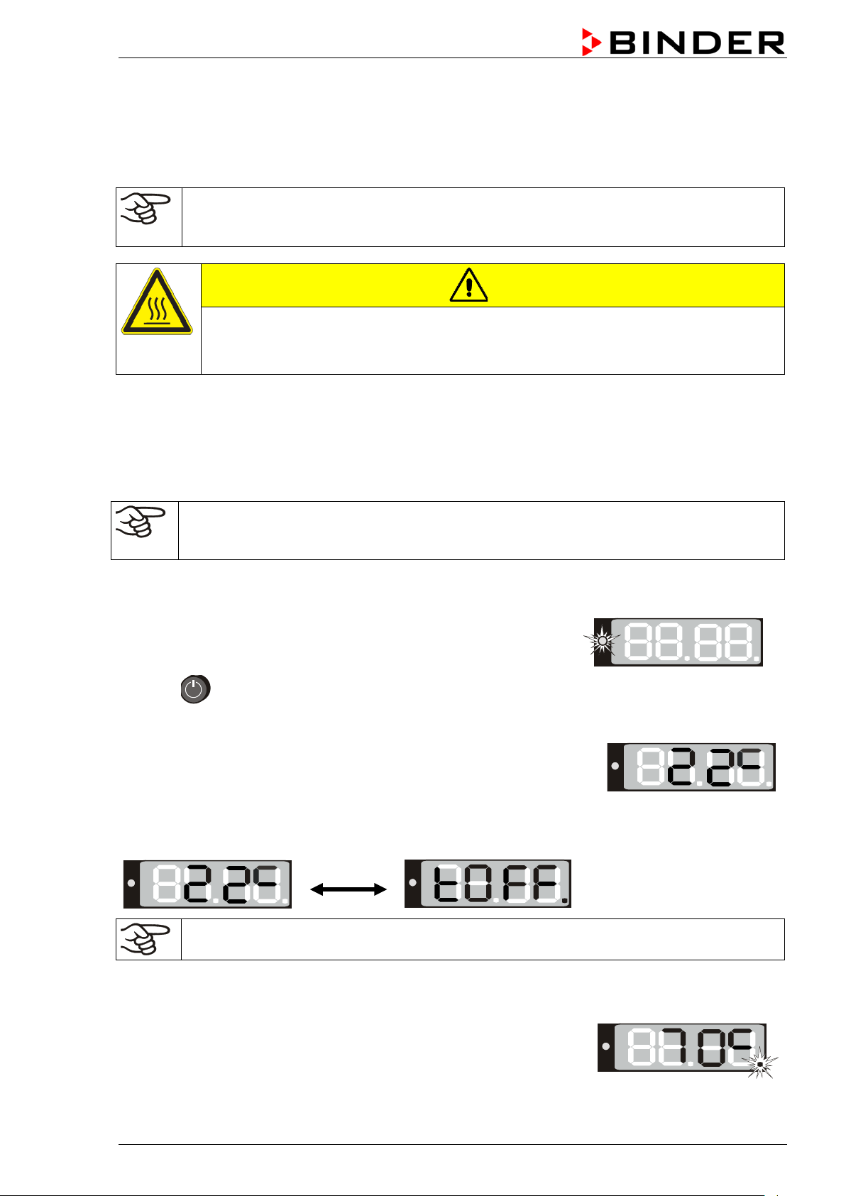
3. Press until the display lights up.
The controller is now in normal display (actual value display).
“Timer operation” with the set time just running down chap. 6.3
actual temperature value (example: 22 °C) is displayed
If the controller is in time function “Timer operation” with no time programmed or the set time run-off
(chap. 6.3), the chamber is inactive (no heating). T he display alternat ely shows the act ual temperature
value (example: 22 °C) and “tOff”:
Adjust the safety device following any changes of the set-point (chap. 7).
5.2 Heating operation display
control light in the bottom right corner of the display slowly begins to
flash depending on the heat requirement (example: 70 °C).
BD / ED / FD (E2) 03/2019 page 17/68
The chamber is operating, the controller is in norm al display (actual val ue
5.3 Air change
Opening the air flap in the exhaust duct serves to adjust the
air change.
Without connecting a suction plant:
• For BD and ED chambers fresh air circulation can be
elevated using the exhaust duct. The air flap in the
exhaust duct serves to adjust the fresh air entry.
• For FD chambers with the air flap open and the fan
operating, fresh air comes in via aeration gaps.
• If the air f lap is c ompletely open, the spa tia l t emperature
accuracy can be negatively influenced.
Figure 5: Adjusting the air flap
6. Opera ti ng t he c ontroller
Controller setting is identical with all thre e chambers BD, ED, an d FD. The temperature controllers onl y
differ in their temperature range (BD: up to 100 °C / 212 °F, ED/FD: up to 300 °C / 572 °F ) and the
displayed accuracy (BD: a tenth of a degree, ED/FD: one degree).
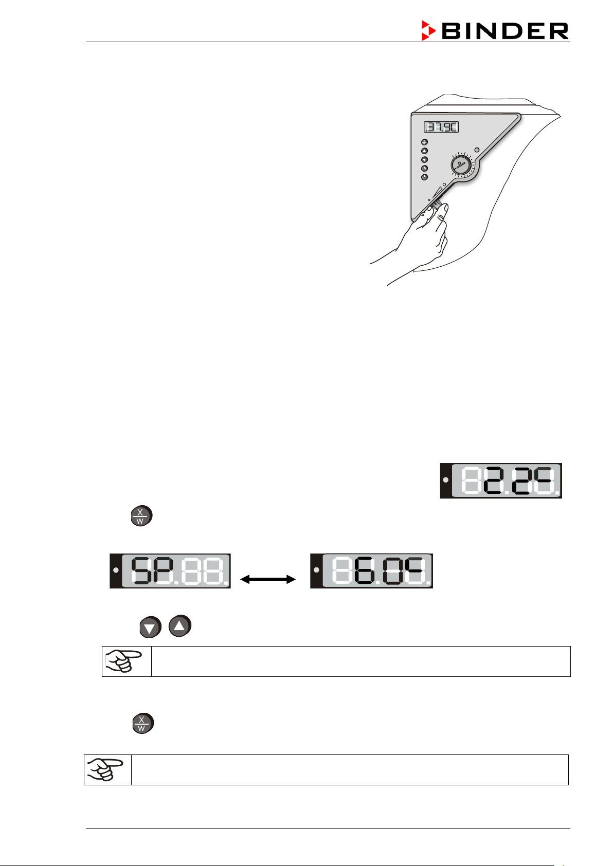
6.1 Display / entry of temperature set-point (without ramp function)
display). The actual temperature value (example: 22 °C) is displayed:
1. Press button
The display shows alternately “SP” and the previous temperature set-point (example: 60 °C):
2. With the buttons enter a set-point value between 0 and 300.
The desired temperature set-point can be selected in a temperature range from 5 °C / 9 °F
above room temperature up to 100 °C / 212 °F (BD) or 300 °C / 572 °F (ED/FD).
3. Wait 2
4. Press button to return to normal display (actual value display) (autom atically after approx. 30
seconds).
BD / ED / FD (E2) 03/2019 page 18/68
seconds until the entered temperature value is taken over (display flashing once).
Adjust the safety device following any changes of the set-point (chap. 7).
The chamber is operating, the controller is in norm al display (actual val ue
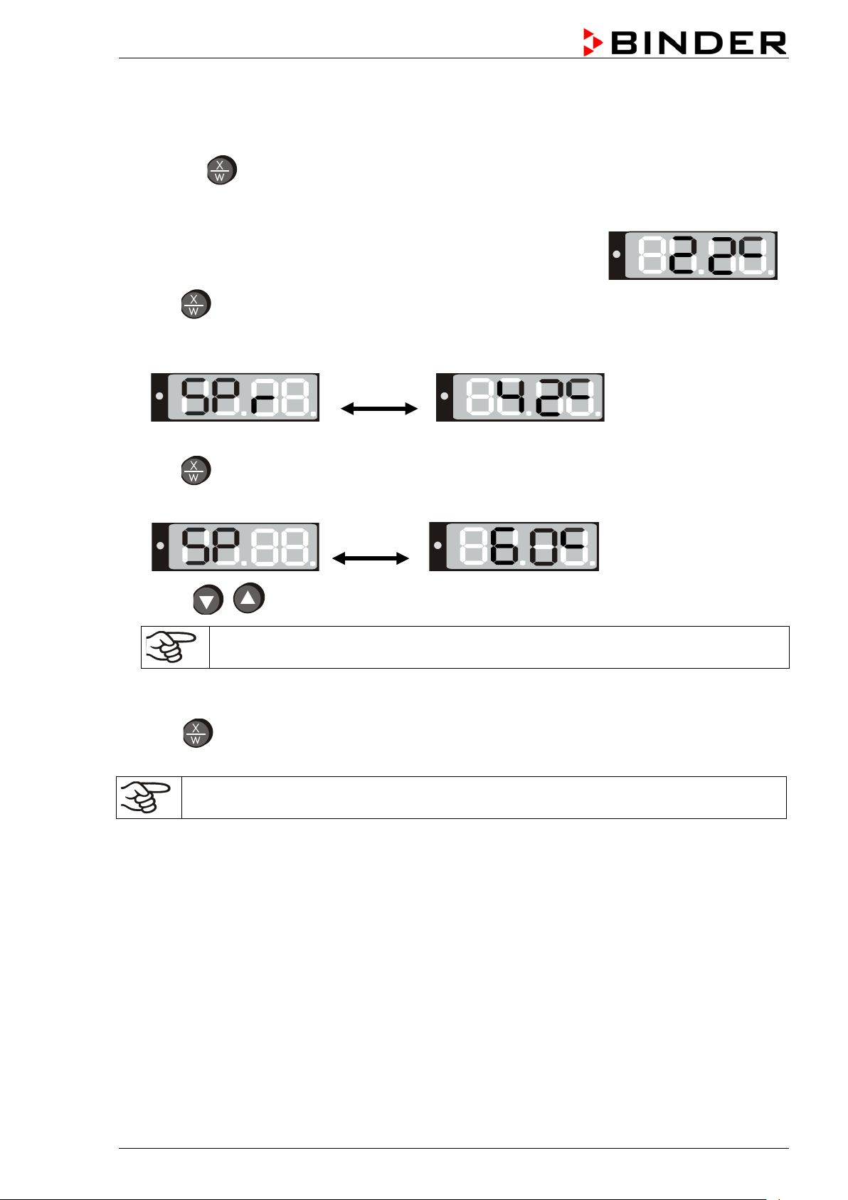
6.2 Display / entry of temperature set-point (with selected temperature ramp)
If previously a temperature ramp value has been selected (chap. 6.4.2):
Press button in normal display / actua l value display during ram p operation to have displayed the
actual temperature ramp set-point, which chang es according to the selected gra dient, in addition to the
entered target set-point for temperature.
display). The actual temperature value (example: 22 °C) is displayed:
1. Press button
The display shows alter nately “SPr” and the actual te mperature ramp set-point changing according
to the selected gradient (example: 42 °C):
This ramp set-point is displayed only, it is not adjustable.
2. Press button
The display shows alternately “SP” and the previous temperature set-point (example: 60 °C):
3. With the buttons enter a set-point value between 0 and 300.
The desired temperature set-point can be selected in a temperature range from 5 °C / 9 °F
above room temperature up to 100 °C / 212 °F (BD) or 300 °C / 572 °F (ED/FD).
4. Wait 2
5. Press button to ret urn to normal display / actual value display (autom atically after approx. 30
seconds until the entered temperature value is taken over (display flashing once).
seconds).
Adjust the safety device following any changes of the set-point (chap. 7).
BD / ED / FD (E2) 03/2019 page 19/68

Timer running
6.3 Time functions: Continuous operation and Timer operation
Press the time management button .
The timer indicates its current time function. There are two possible time functions:
Continuous operation
The display shows alternately “t1” (time function) and the time function “Continuous operation” “t inf”:
The heating and fan (with FD) are permanently active, independent of the timer setting.
Timer operation
The display shows alternately “t1” (time function) and the running-down time or “tOff”:
or
Press button to return to normal display (actual value display) (automatically after approx. 30
seconds).
Remaining time (example: 28 Min.) –
down
Heating and fan (with FD) are active until the timer has rundown.
Timer not programmed or run-down “t off”
If the timer has run-down, heating and fan (with FD) are
permanently off.
BD / ED / FD (E2) 03/2019 page 20/68
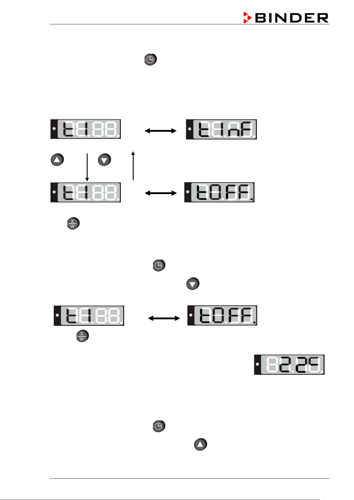
The actual temperature value (example: 22 °C) is displayed:
6.3.1 Switching between “Continuous operation” and “Timer operation”
Press the time management button .
The controller displays the actual time function. In time function “Continuous o peration”, “t1” and “t inf ” are
displayed alternately. In time function “Timer operation”, “t1” is displayed alternately with the runningdown time or “tOff”.
If in time function “Timer operation” the Timer is just running off (“t1”displayed alternately with the runningdown time) the timer m ust first be set to Zero (chap. 6.3.3). Now “t1” is displa yed alternately with “tOff”,
and the controller can be changed to time function “Continuous operation”.
Continuous operation
2 seconds
Timer operation
Press button to return to normal display / actual value display (automatically after approx. 30 sec).
2 seconds
Timer not programmed or run-down
6.3.2 Continuous operation
1. Press the time management button .The timer indicates its current time function.
2. If necessary, switch to timer operation by button .
The display shows alternately “t1” and the time function “Continuous operation” “t inf”:
3. Press button to return to normal display (actual value displa y) (automatically after approx. 30
seconds).
Now the controller o perates with the entered set-point (chap. 6.1) in continuo us operation. The heating
and fan (for FD) are permanently active, independent of the timer setting.
To cancel Continuous operation, proceed accordingly:
1. Press the time management button .
2. Switch to Timer operation by pressing down button for 2 seconds (chap. 6.3.1).
BD / ED / FD (E2) 03/2019 page 21/68
Loading...