


R5 RECUMBENT BIKE OWNER’S MANUAL
BH FITNESS
20155 Ellipse, Foothill Ranch, CA 92610
Phone: 949-206-0330
Fax: 949-206-0013
Email: fitness@bhnorthamerica.com
Web: www.bhnorthamerica.com and www.bhfitness.com
Issued: 6 October 2008 (v1)

R5 RECUMBENT BIKE
TABLE OF CONTENTS |
|
IMPORTANT SAFETY INFORMATION ........................................................................... |
2 |
ASSEMBLY ..................................................................................................................... |
4 |
HEART RATE CALCULATION ...................................................................................... |
18 |
CONSOLE OPERATION ............................................................................................... |
19 |
Buttons ................................................................................................................. |
21 |
Modes ................................................................................................................. |
23 |
Programs.............................................................................................................. |
24 |
Manual Program, CP.1................................................................................. |
25 |
Custom, CP.8............................................................................................... |
27 |
CP.1-CP.7 .................................................................................................... |
28 |
HRC.1-HRC.3, (PROGRAMS 9-11) ........................................................... |
29 |
Appearance of Program Displays ......................................................................... |
31 |
WARRANTY .................................................................................................................. |
37 |
Page 1

R5 RECUMBENT BIKE
IMPORTANT SAFETY INSTRUCTIONS
User Safety
1.Users should pass a full medical examination before they begin an exercise program. Work at the recommended exercise level. Do not over exert yourself. If you feel any pain or discomfort, stop exercising immediately and consult your doctor.
2.Before exercising calculate your maximum heart rate using the formula on page 18.
3.Do warm up stretching exercises before using the unit.
4.Verify that all of the parts are attached and that the nuts, bolts, pedals and bar are correctly tightened before use. Verify that there are not any cracks or sharp edges.
5.Do not wear loose clothing or high heels. Tie up shoe laces.
6.The maximum user weight is 300 pounds (136 Kg).
7.Keep hands away from moving parts.
8.Supervise children, invalids or disabled persons at all times. Children are curious and vulnerable to accidents. Do not use the unit as a toy. Disabled people should not use the exercise equipment without the assistance of a qualified person or doctor. Keep pets away from unit.
9.The owner is responsible for explaining safety instructions to each user.
10.The unit can only be used by one person at a time.
Unit Safety
1.For safety, maintain a minimum clearance around the unit. Maintain 18 inches on the front and on each side of the unit plus 24 inches at the rear of the unit.
2.Install and use the unit on a flat, stable surface, with some type of protection for the floor or carpet. Do not place it alongside walls or furniture. Check the unit before each use.
3.Please read all of the instructions before assembling or using this unit.
4.To reduce the dangers and risk of electric shock always unplug the unit from its electrical power immediately after using, before cleaning, opening, disassembling or doing maintenance.
5.Do not place sharp objects near the exercise equipment.
6.Do not use the exercise equipment if it is not working correctly.
WARNING: To reduce the risk of fire, electric shock, injury to persons or inflicting the harm of a burn:
7.The unit should never be left unattended when plugged in. Unplug the unit from the electrical power before leaving the room, when unused and before adding or removing parts.
8.Do not operate the unit under a blanket or pillow. Excessive heating can occur and cause fire, electric shock, injury to persons or inflict the harm of a burn.
Page 2

R5 RECUMBENT BIKE
IMPORTANT SAFETY INSTRUCTIONS
9.Use the unit only as described in this manual. Only use attachments recommended by the manufacturer.
10.Never operate this unit if it has a damaged electrical cord or plug. Do not operate this unit if it is not working properly. Do not operate this unit if it has been dropped or damaged. Do not operate this unit if it has been immersed into water. Return the unit to a service center for examination and repair.
11.Do not pull or carry the unit by the electrical cord. Do not use the cord as a handle.
12.Keep the electrical cord away from heated surfaces.
13.Never operate the unit when the air openings are blocked. Keep the air openings free of lint, hair and the like.
14.Do not drop or insert any objects into any openings.
15.Do not use outdoors or near water.
16.Do not operate where aerosol (spray) products are being used or where oxygen is being administered.
Adapter Safety
The Adapter may have a polarized plug (one blade is wider than the other). This plug will fit only one way into a polarized outlet. If the plug does not fully fit into the outlet, then reverse the plug. If it still does not fit then contact a qualified Electrician to install the correct outlet. Do not change the plug in any way.
PLEASE SAVE THESE INSTRUCTIONS.
Page 3

R5 RECUMBENT BIKE
ASSEMBLY
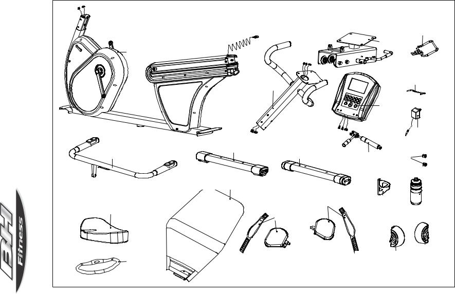
1. Assembly Parts
(108) Allen Bolt M8*15-12PCS or more
(5) Washer 18*9*2.0t -12PCS or more
163
|
|
|
|
|
|
|
|
(109)Bolt M8*56-4PCS |
|
|
|
|
|
|
|
|
|
|
|
|
|
|
|
|
|
|
|
|
(164) Allen Bolt M6*10-1PCS |
|
(110)Acorn Nut M8-4PCS |
|
|
||
|
|
|
|
|
|
|
|
|
|
|
|
|
(161) Allen Bolt M10*15-3PCS |
|
|
|
(166) Washer 18*10*2.0t-1PCS |
|
(112)Spring Washer M8*2.0t-4PCS |
|
|
||
|
(162) Washer 20*10.2*3.0t-3PCS |
|
|
|
(163) Spring washer M6-1PCS |
|
(113)Washer 20*9*2.0t-4PCS |
|
|
||
|
|
|
|
|
|
|
|||||
|
(163) Spring Washer M10*3.0t-3PCS |
|
|
|
|
|
|
|
|
|
|
|
|
|
|
|
|
|
|
|
|
|
|
|
|
|
|
|
|
|
|
|
|
1PCS-Bolt |
M8-1PCS |
|
|
|
|
|
|
|
|
|
|
||
|
|
|
|
|
|
|
|
|
|
||
(118) 6mm Allen Wrench -1PCS |
|
|
|
|
|
|
|
|
NutNylon |
||
|
|
|
|
|
|
|
|
|
|
||
|
|
|
|
(41) Phillips Screw ST4*25-4PCS |
|
|
(91)Allen Bolt M6*35-2PCS |
|
(159) |
(151) |
|
|
|
||||||||||
|
|
|
|
|
|
|
|
|
|
||
|
|
|
|
|
|
|
|
|
|
||
151
(117)Wrench-1PCS
(116) 4mm Allen Wrench-1PCS
(151) Nylon Nut M8-1PCS (160) Allen Bolt M8*20-1PCS
Page 4
RECUMBENT BIKE |
|
|
|
|
|
|
|
R5 |
|
|
|
|
|
|
|
|
|
|
Seat Sliding Base (51) |
Hand Rail (96) |
|
||
|
|
|
|
|
|
||
|
|
|
|
|
(96) |
|
|
|
|
|
|
|
(51) |
|
|
Front Frame (1) |
|
|
|
|
|
|
|
(1) |
|
|
|
|
|
|
|
|
|
|
|
|
Book Shelf iron |
|
|
|
|
|
|
|
string (104) (104) |
|
|
ASSEMBLY |
|
Upright (80)(80) |
|
|
|
|
|
|
|
|
|
(97) |
|
Page 5 |
|
|
|
|
|
Computer (97) |
|
||
|
|
|
|
|
(127) |
||
Rear Stabilizer (74) |
|
|
|
Adaptor (127) |
|||
Handrail (59) |
|
(74) |
Front Stabilizer (66) |
|
|
|
|
|
|
|
|
|
|
||
(59) |
|
|
(66) |
|
|
|
|
|
|
|
|
(157) |
(90) |
|
|
|
|
|
|
Cylinder (157) |
Plastic Pad (90) |
|
|
|
Backrest Frame |
(158) |
|
|
|
|
|
|
(158) |
|
|
|
(106) |
|
|
|
|
|
|
|
|
|
|
|
|
|
|
|
|
Bottle (106) |
|
|
|
|
Pedal (R) (120) |
|
|
|
|
|
|
|
( )(120) |
Bottle Holder (107) |
|
|
|
Seat (102) |
|
|
(107) |
|
|
||
(102) |
|
|
Pedal (L) (119) |
|
|
|
|
|
|
|
|
|
|
|
|
|
|
|
( )(119) |
|
|
|
|
|
|
|
|
(48) |
(49) |
|
|
|
|
|
|
|
|
||
(126) |
|
|
|
Decoration Cover (L) (48) |
|
|
|
Chest Belt (126) |
|
|
|
|
|
|
|
|
|
|
|
|
Decoration Cover (R) (49) |
|
|

R5 RECUMBENT BIKE
ASSEMBLY
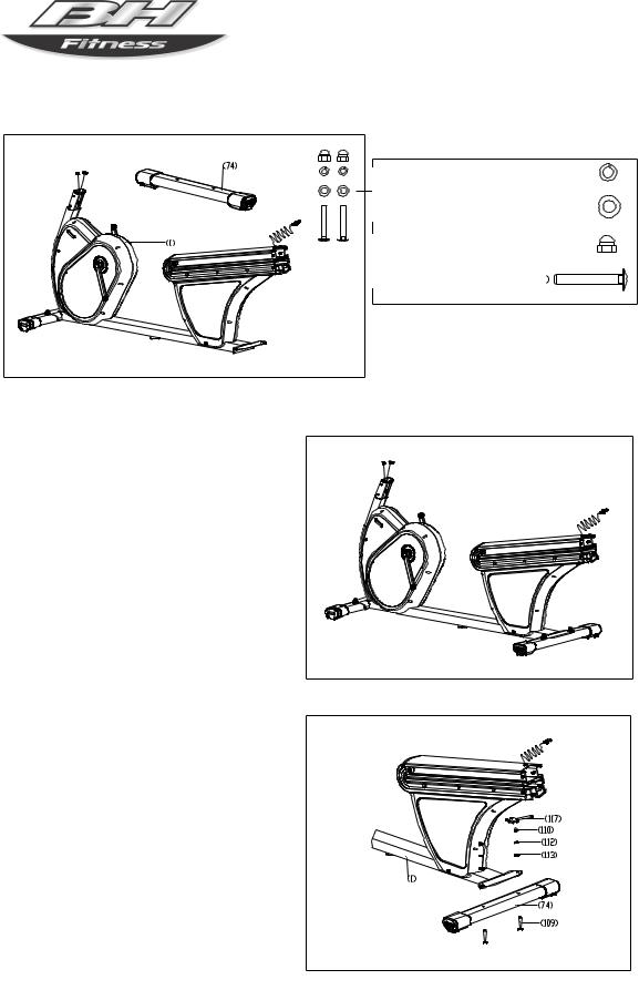
2. Assemble the Front Stabilizer
Appearance after |
assembled |
Spring Washer M8*2.0T – 2PCS (112)
Washer 20*9*2.0T – 2PCS (113)
M8 Acorn Nut – 2PCS (110)
Screw M8*56 – 2PCS (109)


Lift Frame (1) up onto packaging or foam to assist with assembly.
Refer to the right drawing, attach the Front Stabilizer (66) to the Frame (1) with Bolts (109), Washers (113) (112), Acorn Nuts (110), then tighten the nuts with Open Spanner (117).
Page 6
R5 RECUMBENT BIKE
ASSEMBLY
3. Assemble the Rear Stabilizer


Spring Washer M8*2.0T – 2PCS (112)
Washer 20*9*2.0T – 2PCS (113)


M8 Acorn Nut – 2PCS (110)
Screw M8*56 – 2PCS (109)

Appearance after assembled
Lift Frame (1) up onto packaging or foam to assist with assembly.
Refer to the right drawing, attach the Rear Stabilizer (74) to the Frame (1) with Bolts (109), Washers (113) (112), Acorn Nuts (110), then tighten the nuts with Open Spanner (117).
Remove packaging or foam under
Frame (1).
Page 7

R5 RECUMBENT BIKE
ASSEMBLY
4. Assemble the Upright
Appearance after |
assembled |
Washer 8*9*2.0t–6 PCS (5)
Wahser 18*9*2.0t—6PCS (5)
M8x15--6PCS(108)
Bolt M8*16—6PCS (108)
Step A: 1. Connect the Hand Pulse Wires (17) and (83) between the Front Frame (1) and the Upright (80), and then connect the Hand Pulse Wires (105) and (122).
2. Insert the Upright (80) into the Frame (1), then assemble the Upright and Frame with Washer (5), Bolts (108) and 6mm Allen Wrench (118).
Page 8
R5 RECUMBENT BIKE
ASSEMBLY
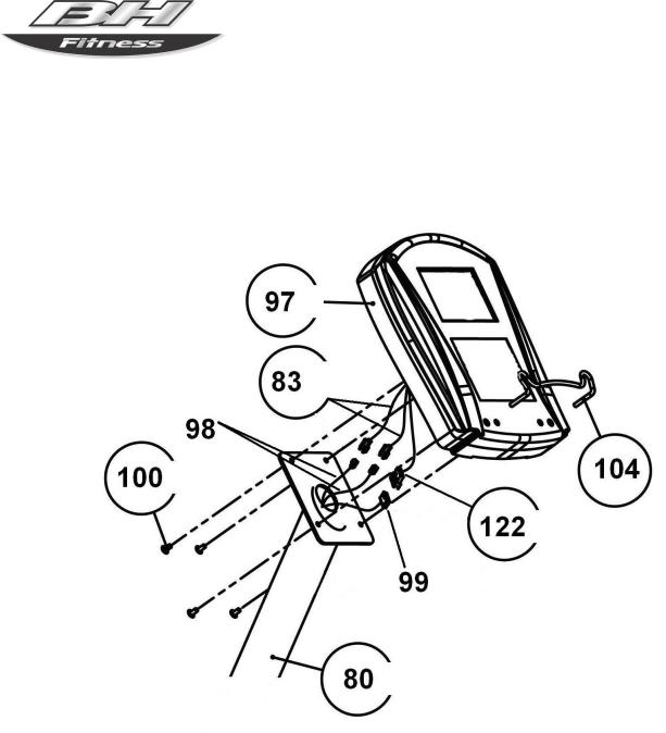
5. Assemble the Computer
Connect the control wires (99) and (122). Connect the hand pulse wires (83) and (98). Secure the computer on the upright (80) with four screws (100). Insert the book shelf iron string (104) into the computer.
Page 9
R5 RECUMBENT BIKE
ASSEMBLY
6. Assemble the Seat, Handrail, Seat Sliding Base, Spacers and Rear Covers
Appearance after |
assembled |
Phillips Screw ST4.0*25ST4-4PCS.0x25(41)--4PCS(41)
Allen Bolt M6*35M6x35-2PCS(91)--2PCS(91)
18x9x2.0t--4PCS(5)
Washer18*9*2.0t-4PCS(5) Allen Bolt M8*15M8x15-4PCS(108)--4PCS(108)
Allen Bolt M10*15-3PCS(161)
M10x15--3PCS(161)
Spring Washer M10*3.0t-3PCS(163)
M10x3.0t--3PCS(163)
Washer 20*10.2*3.0t-3PCS(162)
20x10.2x3.0t--3PCS(162)
Allen Bolt-1PCS(159)
--1PCS(159)
NylonM8Nut--1PCS(151)M8-1PCS(151)
Step A: Attach the Seat (102) to the Seat Sliding Base (51) with Washers (5), Bolts (108), and 6mm Allen Wrench (118).
Page 10
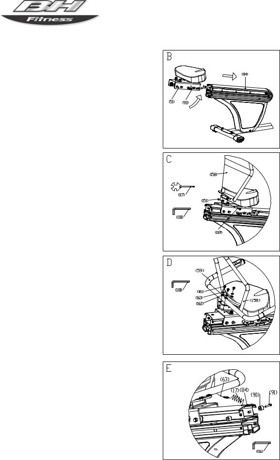
Step B: Turn the Handle (93) of the Seat Sliding Base (51) in the direction shown in the right drawing. Slide the Seat Sliding Base onto the Aluminous Tube (84) and then release the Handle.
Step C: Put the bushing of the Backrest Frame (158) into the U-iron plate of the Seat Sliding Base (151). Put Allen Bolt (159) into bushing and plate, then tighten bolt with Nylon Nut (151) by Wrench (117) and 6mm Allen Wrench (118).
Step D: Attach the Handle (59) to the Backrest Frame (158) with Bolt (161), Spring Washer (163), Washer (162) and 6mm Allen Wrench (118).
Step E:
1. Attach the Spacers (90) to the Aluminous Tube (84) with Bolts (91) and Allen Wrench (116).
2. Connect Hand Pulse Wires (rear frame section) (17) with (handrail section) (63).
R5 RECUMBENT BIKE
ASSEMBLY |
Page 11
 Loading...