


BH FITNESS H-916 SB2 INDOOR CYCLEEEE
OWNER S MANUAL
BH FITNESS
20155 Ellipse, Foothill Ranch, CA 92610
Phone: 949-206-0330 , 866-325-2339 (USA & Canada) Fax: 949-206-0013
Email: fitness@bhnorthamerica.com
Web: www.bhnorthamerica.com and www.bhfitness.com
Issued: 28 May 2008 (v1)
H-916 SB2 Indoor Cycle |
1 |

IMPORTANT SAFETY INSTRUCTIONS
User Safety
1.Users should pass a full medical examination before they begin an exercise program. Work at the recommended exercise level. Do not over exert yourself. If you feel any pain or discomfort, stop exercising immediately and consult your doctor.
2.Verify that all of the parts are attached and that the nuts, bolts, pedals and bar are correctly tightened before use.
3.Do no wear loose clothing or high heels. Tie up shoe laces.
4.The maximum weight of a user is 300 pounds (136 Kg).
5.Keep hands away from moving parts.
6.Supervise children at all times. Children are curious and vulnerable to accidents. Do not use the unit as a toy.
7.The owner is responsible for explaining safety instructions to each user.
8.The unit can only be used by one person at a time.
9.This unit must only be used for the purposes described in this manual. DO NOT use accessories that are not recommended by the manufacturer.
10.Do not place sharp objects near the unit.
11.Do warm up stretching exercises before using the unit.
12.Do not use the bicycle if it is not working correctly.
Bike Safety
For safety, maintain a minimum clearance around the unit. Maintain 18 inches on the front and on each side of the unit plus 24 inches at the rear of the unit.
Install and use the unit on a flat, stable surface, with some type of protection for the floor or carpet. Do not place it alongside walls or furniture. Check the unit before each use.
Please read all of the instructions before assembling or using this unit.
Please save these instructions.
EXERCISE GUIDE
Before beginning to exercise, calculate your maximum heart rate. The maximum number of heartbeats that a person must not exceed is referred to as the maximum heart rate and this value drops with age. A simple formula to calculate this is to subtract your age, in years from the number 220. To ensure that you are exercising correctly, try to keep between 65% and 85% of your maximum heart rate value. Do not exceed 85% of your maximum heart rate.
For example, the maximum heart rate that a 30 year old user must not exceed is: 220 – 30 = 190 beats per minute (BPM).
190 x 0.65 = 123 heart beats per minute.
190 x 0.85 = 161 heart beats per minute.
So the heart rate exercise range for a 30 year old is between 123 and 161 heart beats per minute (BPM).
H-916 SB2 Indoor Cycle |
2 |
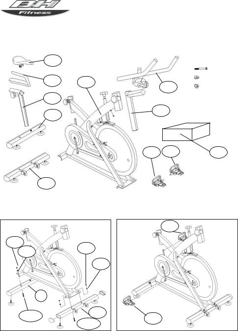
ASSEMBLY GUIDE
Figure 1
F
G A
H
I
J
Figure 2
8
8
9
9
|
I |
10 |
J |
|
|
|
10 |
|
|
|
10 |
(4 each) |
||
|
|
|
||||
B |
|
|
9 |
(4 each) |
||
|
|
|||||
|
|
8 |
(4 each) |
|||
|
|
|||||
 Spanner Wrench (1 each)
C
R L M
Figure 3
L
R
H-916 SB2 Indoor Cycle |
3 |

Figure 4
F
T
G A
H
Figure 6
m
n
k
h
Figure 8
ASSEMBLY GUIDE
Figure 5
|
B |
|
Z |
|
Y |
S |
V |
|
|
|
A |
T C
Figure 7
Z
13
15
H-916 SB2 Indoor Cycle |
4 |

ASSEMBLY GUIDE
1. ASSEMBLY INSTRUCTIONS
(Figure 1).The assistance of a second person is recommended when assembling this unit. Take the unit out of its box and verify the parts are undamaged and quantities are correct.
1.(A) Main body; (B) Handlebar; (C) Handlebar stem;
(H) Saddle post; (G) Horizontal saddle tube; (F) Saddle; (I) Rear stabilizer bar with adjustable feet; (J) Front stabilizer bar with wheels; (L) Left pedal; (R) Right pedal; (M) Monitor casing and components; (10) Slot head bolt M 10; (9) Flat washer M 10; (8) Cap nut M 10; Double ended spanner wrench.
2.Figure 2. Position the rear stand of main body (A) on the rear stabilizer bar (I). Insert the bolts (10), fit the flat washers (9) and cap nuts (8) and then tighten securely.
3.Figure 2. Position the front stabilizer bar with wheels (J), paying attention to the red dots and with the wheels facing forwards. Insert the bolts (10), fit the flat washers (9) and cap nuts (8) and tighten securely.
2. FIT THE PEDALS
The assembly instructions for the pedals must be followed exactly, fitting these incorrectly could damage the screw thread on either the pedal or the crank.
Right and left refer to the position that the user adopts when sitting on the saddle to do the exercises.
Figure 3. The right pedal, marked with the letter (R), screws onto the right crank, also marked with an (R), in a clockwise direction. Tighten securely.
Figure 3. The left pedal, marked with the letter (L), screws onto the left crank, also marked with an (L), in an counterclockwise direction. Tighten securely.
3. ATTACH THE SADDLE
Figure 4. Fit the saddle bracket (F), onto the horizontal saddle tube (G). Fit the saddle into position and tighten the nuts onto the bracket securely. Next insert the horizontal saddle tube (G) through the hole on the saddle post (H).
Figure 5. Position it correctly and tighten the knob (S). Insert the saddle post (H) into the boss on the main body (A), position it comfortable for doing exercise and tighten the saddle post by using the adjustment knob
(T) turning it clockwise.
ADJUST THE SADDLE HEIGHT
Figure 4. Loosen the saddle post adjustment knob (T) slightly by turning it counterclockwise, move the saddle to a position comfortable for doing exercise
and then tighten the adjustment knob (T) securely by turning it clockwise.
HORIZONTAL ADJUSTMENT OF THE SADDLE
Figure 5. Loosen the knob (S) slightly by turning it counterclockwise. Move the saddle to a position comfortable for doing exercise and then tighten the knob (S) securely by turning it clockwise.
4. FIT THE HANDLEBAR
Figure 5. Position the handlebar (B) on the handlebar stem (C). Tighten the knob (V) and then insert the handlebar stem (C) into the hole on the main body (A). Position it correctly and then tighten knob (Y) by turning it clockwise.
ADJUST THE HANDLEBAR HORIZONTALLY
Figure 5. Position the handlebar (B) at a comfortable distance for doing exercise but without going beyond the “MAX” marks, now tighten knob (V) securely.
ADJUST THE HANDLEBAR VERTICALLY
Figure 5. Position the handlebar (B) at a comfortable distance for doing exercise but without going beyond the “MAX” marks, now tighten knob (Y) securely.
5. ATTACH THE MONITOR
Figure 6. Fit the monitor (m) into the bracket (n). Take the middle cable and connect terminal (h) to terminal (k), coming out of the bottom of the main body (A). Insert the jack on the middle cable into the back of the monitor (see the following instructions for the monitor).
EXERTION SETTINGS
Figure 7. To provide an even level of exertion during exercise, this appliance is equipped with a tensioning control (Z), located on the stem of the main body (A). This provides various exertion settings when turned.
To increase/decrease pedal resistance turn the tensioning control (Z) until the exertion level best suits your exercise requirements.
During exercise the flywheel will get hot due to the braking effect, so when you have finished exercising it is advisable to set the tensioning control (Z) to minimum in order to help stop the brake shoe from hardening.
Important:
Figure 7. This tensioning control (Z) is equipped with an emergency braking system which, when applied with force (as shown by the arrow in Figure 7), produces a much sharper braking effect.
H-916 SB2 Indoor Cycle |
5 |
 Loading...