

Page 1
CENTRALINA UNIVERSALE PER IL CONTROLLO DI UNO O DUE MOTORI
UNIVERSAL CONTROL UNIT FOR ONE OR TWO MOTORS
CENTRALE UNIVERSELLE PERMETTANT DE CONTRÔLER UN OU DEUX MOTEUR
UNIVERSALSTEUERGERÄT ZUR STEUERUNG VON EINEM ODER ZWEI MOTOREN
CENTRALITA UNIVERSAL PARA CONTROLAR UNO O DOS MOTORES
UNIVERSELE BESTURINGSEENHEID VOOR DE BESTURING VAN 1 OF 2 MOTOREN
D812865 00100_04 23-12-16
MONTAGEANLEITUNG
ISTRUZIONI DI INSTALLAZIONE
INSTALLATION MANUAL
INSTRUCTIONS D’INSTALLATION
INSTRUCCIONES DE INSTALACION
INSTALLATIEVOORSCHRIFTEN
Attenzione! Leggere attentamente le “Avvertenze” all’interno! Caution! Read “Warnings” inside carefully! Attention! Veuillez lire attentivement les Avertissements qui se trouvent à l’intérieur! Achtung! Bitte lesen Sie
aufmerksam die „Hinweise“ im Inneren! ¡Atención¡ Leer atentamente las “Advertencias”en el interior! Let op! Lees de “Waarschuwingen” aan de binnenkant zorgvuldig!
RIGEL 6
Page 2
Any other use constitutes improper use and,
consequently, is hazardous. The manufacturer
cannot be held liable for any damage as a result
of improper, incorrect or unreasonable use.
GENERAL SAFETY
Thank you for choosing this product. The Firm is
condent that its performance will meet your ope-
rating needs.
This product meets recognized technical standards
and complies with safety provisions when installed
correctly by qualied, expert personnel (professional
installer).
If installed and used correctly, the automated system
will meet operating safety standards. Nonetheless,
it is advisable to observe certain rules of behaviour
so that accidental problems can be avoided:
- Keep adults, children and property out of range of
the automated system, especially while it is moving.
- Do not allow children to play or stand within range
of the automated system.
- The unit can be used by children over 8 years old
and by people with reduced physical, sensory or
mental capabilities or with no experience or neces-
sary knowledge on condition they are supervised
or trained about the safe use of the equipment
and understand the risks involved. Children must
not play with the unit. Cleaning and maintenance
must not be performed by unsupervised children.
- Children must be supervised to ensure they do not
play with the device. Do not allow children to play
with the xed controls. Keep remote controls out
of reach of children.
-
Do not work near hinges or moving mechanical parts.
- Do not hinder the leaf’s movement and do not
attempt to open the door manually unless the ac-
tuator has been released with the relevant release
knob.
- Keep out of range of the motorized door or gate
while they are moving.
- Keep remote controls or other control devices out
of reach of children in order to avoid the automated
system being operated inadvertently.
- The manual release’s activation could result in un-
controlled door movements if there are mechanical
faults or loss of balance.
- When using roller shutter openers: keep an eye
on the roller shutter while it is moving and keep
people away until it has closed completely. Exercise
care when activating the release, if such a device
is tted, as an open shutter could drop quickly in
the event of wear or breakage.
- The breakage or wear of any mechanical parts of
the door (operated part), such as cables, springs,
supports, hinges, guides…, may generate a hazard.
Have the system checked by qualied, expert per-
sonnel (professional installer) at regular intervals
according to the instructions issued by the installer
or manufacturer of the door.
- When cleaning the outside, always cut o mains
power.
- Keep the photocells’ optics and illuminating in-
dicator devices clean. Check that no branches or
shrubs interfere with the safety devices.
- Do not use the automated system if it is in need of
repair. In the event the automated system breaks
down or malfunctions, cut o mains power to the
system; do not attempt to repair or perform any
other work to rectify the fault yourself and instead
call in qualied, expert personnel (professional
installer) to perform the necessary repairs or main-
tenance. To allow access, activate the emergency
release (where tted).
- If any part of the automated system requires direct
work of any kind that is not contemplated herein,
employ the services of qualied, expert personnel
(professional installer).
- At least once a year, have the automated system, and
especially all safety devices, checked by qualied,
expert personnel (professional installer) to make
sure that it is undamaged and working properly.
- A record must be made of any installation, main-
tenance and repair work and the relevant docu-
mentation kept and made available to the user on
request.
- Failure to comply with the above may result in
hazardous situations.
SCRAPPING
Materials must be disposed of in accordance
with the regulations in force. Do not throw
away your discarded equipment or used bat-
teries with household waste. You are respon-
sible for taking all your waste electrical and
electronic equipment to a suitable recycling
centre.
Anything that is not explicitly provided for in the
user guide is not allowed. The operator’s proper
operation can only be guaranteed if the instruc-
tions given herein are complied with. The Firm
shall not be answerable for damage caused by
failure to comply with the instructions featured
herein.
While we will not alter the product’s essential
features, the Firm reserves the right, at any time,
to make those changes deemed opportune to
improve the product from a technical, design or
commercial point of view, and will not be required
to update this publication accordingly.
AVERTISSEMENTS POUR L’UTILISATEUR (F)
ATTENTION ! Instructions de sécurité importan-
tes. Veuillez lire et suivre attentivement tous les
avertissements et toutes les instructions fournis
avec le produit sachant qu’un usage incorrect
peut provoquer des préjudices aux personnes,
aux animaux ou aux biens. Veuillez conserver
les instructions pour d’ultérieures consultations
et pour les transmettre aux propriétaires futurs
éventuels.
Cet appareil ne peut être destiné qu’à l’usage
pour lequel il a été expressément installé. Tout
autre usage sera considéré comme impropre et
donc dangereux. Le fabricant ne sera en aucun
cas considéré comme responsable des préjudices
dus à un usage impropre, erroné ou déraisonné.
SECURITE GÉNÉRALE
Nous vous remercions d’avoir choisi ce produit
qui, nous n’en doutons pas, saura vous garantir les
performances attendues.
Ce produit, correctement installé par du personnel
qualié et expérimenté (monteur professionnel) est
conforme aux normes reconnues de la technique et
des prescriptions de sécurité.
Si l’automatisation est montée et utilisée correcte-
ment, elle garantit la sécurité d’utilisation prescrite.
Il est cependant nécessaire de respecter certaines
règles de comportement pour éviter tout inconvé-
nient accidentel.
- Tenir les enfants, les personnes et les objets à l’écart
D811767_08
AVVERTENZE PER L’UTILIZZATORE ( I )
ATTENZIONE! Importanti istruzioni di sicurezza.
Leggere e seguire attentamente le Avvertenze
e le Istruzioni che accompagnano il prodotto
poiché un uso improprio può causare danni a
persone, animali o cose. Conservare le istruzioni
per consultazioni future e trasmetterle ad eventuali subentranti nell’uso dell’impianto.
Questo prodotto dovrà essere destinato solo
all’uso per il quale è stato espressamente installato. Ogni altro uso è da considerarsi improprio
e quindi pericoloso. Il costruttore non può essere
considerato responsabile per eventuali danni
causati da usi impropri, erronei e irragionevoli.
SICUREZZA GENERALE
Nel ringraziarVi per la preferenza accordata a questo
prodotto, la Ditta è certa che da esso otterrete le
prestazioni necessarie al Vostro uso.
Questo prodotto risponde alle norme riconosciute
della tecnica e della disposizioni relative alla sicurezza se correttamente installato da personale
qualicato ed esperto (installatore professionale).
L’automazione, se installata ed utilizzata correttamente, soddisfa gli standard di sicurezza nell’uso.
Tuttavia è opportuno osservare alcune regole di
comportamento per evitare inconvenienti accidentali:
- Tenere bambini, persone e cose fuori dal raggio
d’azione dell’automazione, in particolare durante
il movimento.
- Non permettere a bambini di giocare o sostare nel
raggio di azione dell’automazione.
- L’apparecchio può essere utilizzato da bambini di
età non inferiore a 8 anni e da persone con ridotte capacità siche, sensoriali o mentali, o prive di
esperienza o della necessaria conoscenza, purché
sotto sorveglianza oppure dopo che le stesse
abbiano ricevuto istruzioni relative all’uso sicuro
dell’apparecchio e alla comprensione dei pericoli
ad esso inerenti. I bambini non devono giocare con
l’apparecchio. La pulizia e la manutenzione destinata ad essere eettuata dall’utilizzatore non deve
essere eettuata da bambini senza sorveglianza.
- I bambini devono essere sorvegliati per sincerarsi
che non giochino con l’apparecchio. Non permettere ai bambini di giocare con i controlli ssi. Tenere
i telecomandi lontani dai bambini.
-
Evitare di operare in prossimità delle cerniere o organi
meccanici in movimento.
-
Non contrastare il movimento dell’anta e non tentare di aprire manualmente la porta se non è stato
sbloccato l’attuatore con l’apposito sblocco.
-
Non entrare nel raggio di azione della porta o cancello motorizzati durante il loro movimento.
- Non lasciare radiocomandi o altri dispositivi di
comando alla portata dei bambini onde evitare
azionamenti involontari.
- L’attivazione dello sblocco manuale potrebbe
causare movimenti incontrollati della porta se in
presenza di guasti meccanici o di condizioni di
squilibrio.
- In caso di apritapparelle: sorvegliare la tapparella
in movimento e tenere lontano le persone nché
non è completamente chiusa. Porre cura quando si
aziona lo sblocco se presente, poiché una tapparella
aperta potrebbe cadere rapidamente in presenza
di usura o rotture.
-
La rottura o l’usura di organi meccanici della porta
(parte guidata), quali ad esempio cavi, molle, sup-
porti, cardini, guide.. potrebbe generare pericoli. Far
controllare periodicamente l’impianto da personale
qualicato ed esperto (installatore professionale)
secondo quanto indicato dall’installatore o dal
costruttore della porta.
- Per ogni operazione di pulizia esterna, togliere
l’alimentazione di rete.
- Tenere pulite le ottiche delle fotocellule ed i dispositivi di segnalazione luminosa. Controllare che rami
ed arbusti non disturbino i dispositivi di sicurezza.
- Non utilizzare l’automatismo se necessita di
interventi di riparazione. In caso di guasto o di
malfunzionamento dell’automazione, togliere
l’alimentazione di rete sull’automazione, astenersi
da qualsiasi tentativo di riparazione o intervento
diretto e rivolgersi solo a personale qualicato ed
esperto (installatore professionale) per la necessaria riparazione o manutenzione. Per consentire
l’accesso, attivare lo sblocco di emergenza (se
presente).
-
Per qualsiasi intervento diretto sull’automazione o
sull’impianto non previsto dal presente manuale,
avvalersi di personale qualicato ed esperto (installatore professionale).
- Con frequenza almeno annuale far verificare l’integrità e il corretto funzionamento
dell’automazione da personale qualificato ed
esperto (installatore professionale), in particolare
di tutti i dispositivi di sicurezza.
- Gli interventi d’installazione, manutenzione e
riparazione devono essere documentati e la
relativa documentazione tenuta a disposizione
dell’utilizzatore.
- Il mancato rispetto di quanto sopra può creare
situazioni di pericolo.
L’eliminazione dei materiali va fatta rispettan-
DEMOLIZIONE
do le norme vigenti. Non gettate il vostro
apparecchio scartato, le pile o le batterie usate
nei riuti domestici. Avete la responsabilità di
Tutto quello che non è espressamente previsto nel manuale d’uso, non è permesso. ll buon
funzionamento dell’operatore è garantito solo
se vengono rispettate le prescrizioni riportate
in questo manuale. La Ditta non risponde dei
danni causati dall’inosservanza delle indicazioni
riportate in questo manuale.
Lasciando inalterate le caratteristiche essenziali
del prodotto, la Ditta si riserva di apportare in
qualunque momento le modiche che essa ritiene convenienti per migliorare tecnicamente, costruttivamente e commercialmente il prodotto,
senza impegnarsi ad aggiornare la presente
pubblicazione.
restituire tutti i vostri riuti da apparecchiature elettriche o elettroniche lasciandoli in
un punto di raccolta dedicato al loro riciclo.
USER WARNINGS (GB)
WARNING! Important safety instructions. Carefully read and comply with the Warnings and
Instructions that come with the product as improper use can cause injury to people and animals
and damage to property. Keep the instructions
for future reference and hand them on to any
new users.
This product is meant to be used only for the
purpose for which it was explicitly installed.
D812865 00100_04
2 - RIGEL 6
D811767_08
Page 3
Any other use constitutes improper use and,
consequently, is hazardous. The manufacturer
cannot be held liable for any damage as a result
of improper, incorrect or unreasonable use.
D812865 00100_04
GENERAL SAFETY
Thank you for choosing this product. The Firm is
condent that its performance will meet your operating needs.
This product meets recognized technical standards
and complies with safety provisions when installed
correctly by qualied, expert personnel (professional
installer).
If installed and used correctly, the automated system
will meet operating safety standards. Nonetheless,
it is advisable to observe certain rules of behaviour
so that accidental problems can be avoided:
- Keep adults, children and property out of range of
the automated system, especially while it is moving.
- Do not allow children to play or stand within range
of the automated system.
- The unit can be used by children over 8 years old
and by people with reduced physical, sensory or
mental capabilities or with no experience or necessary knowledge on condition they are supervised
or trained about the safe use of the equipment
and understand the risks involved. Children must
not play with the unit. Cleaning and maintenance
must not be performed by unsupervised children.
- Children must be supervised to ensure they do not
play with the device. Do not allow children to play
with the xed controls. Keep remote controls out
of reach of children.
-
Do not work near hinges or moving mechanical parts.
- Do not hinder the leaf’s movement and do not
attempt to open the door manually unless the actuator has been released with the relevant release
knob.
- Keep out of range of the motorized door or gate
while they are moving.
- Keep remote controls or other control devices out
of reach of children in order to avoid the automated
system being operated inadvertently.
- The manual release’s activation could result in uncontrolled door movements if there are mechanical
faults or loss of balance.
- When using roller shutter openers: keep an eye
on the roller shutter while it is moving and keep
people away until it has closed completely. Exercise
care when activating the release, if such a device
is tted, as an open shutter could drop quickly in
the event of wear or breakage.
- The breakage or wear of any mechanical parts of
the door (operated part), such as cables, springs,
supports, hinges, guides…, may generate a hazard.
Have the system checked by qualied, expert personnel (professional installer) at regular intervals
according to the instructions issued by the installer
or manufacturer of the door.
- When cleaning the outside, always cut o mains
power.
- Keep the photocells’ optics and illuminating indicator devices clean. Check that no branches or
shrubs interfere with the safety devices.
- Do not use the automated system if it is in need of
repair. In the event the automated system breaks
down or malfunctions, cut o mains power to the
system; do not attempt to repair or perform any
other work to rectify the fault yourself and instead
call in qualied, expert personnel (professional
installer) to perform the necessary repairs or main-
tenance. To allow access, activate the emergency
release (where tted).
- If any part of the automated system requires direct
work of any kind that is not contemplated herein,
employ the services of qualied, expert personnel
(professional installer).
- At least once a year, have the automated system, and
especially all safety devices, checked by qualied,
expert personnel (professional installer) to make
sure that it is undamaged and working properly.
- A record must be made of any installation, maintenance and repair work and the relevant documentation kept and made available to the user on
request.
- Failure to comply with the above may result in
hazardous situations.
SCRAPPING
Materials must be disposed of in accordance
with the regulations in force. Do not throw
away your discarded equipment or used batteries with household waste. You are responsible for taking all your waste electrical and
electronic equipment to a suitable recycling
centre.
Anything that is not explicitly provided for in the
user guide is not allowed. The operator’s proper
operation can only be guaranteed if the instructions given herein are complied with. The Firm
shall not be answerable for damage caused by
failure to comply with the instructions featured
herein.
While we will not alter the product’s essential
features, the Firm reserves the right, at any time,
to make those changes deemed opportune to
improve the product from a technical, design or
commercial point of view, and will not be required
to update this publication accordingly.
AVERTISSEMENTS POUR L’UTILISATEUR (F)
ATTENTION ! Instructions de sécurité importantes. Veuillez lire et suivre attentivement tous les
avertissements et toutes les instructions fournis
avec le produit sachant qu’un usage incorrect
peut provoquer des préjudices aux personnes,
aux animaux ou aux biens. Veuillez conserver
les instructions pour d’ultérieures consultations
et pour les transmettre aux propriétaires futurs
éventuels.
Cet appareil ne peut être destiné qu’à l’usage
pour lequel il a été expressément installé. Tout
autre usage sera considéré comme impropre et
donc dangereux. Le fabricant ne sera en aucun
cas considéré comme responsable des préjudices
dus à un usage impropre, erroné ou déraisonné.
SECURITE GÉNÉRALE
Nous vous remercions d’avoir choisi ce produit
qui, nous n’en doutons pas, saura vous garantir les
performances attendues.
Ce produit, correctement installé par du personnel
qualié et expérimenté (monteur professionnel) est
conforme aux normes reconnues de la technique et
des prescriptions de sécurité.
Si l’automatisation est montée et utilisée correctement, elle garantit la sécurité d’utilisation prescrite.
Il est cependant nécessaire de respecter certaines
règles de comportement pour éviter tout inconvénient accidentel.
- Tenir les enfants, les personnes et les objets à l’écart
D811767_08
RIGEL 6 - 3
Page 4

du rayon d’action de l’automatisation, en particulier
pendant son fonctionnement.
- Empêcher les enfants de jouer ou de stationner
dans le rayon d’action de l’automatisation.
- Les enfants de plus de 8 ans et les personnes ayant
des capacités physiques, sensorielles ou mentales
diminuées ou n’ayant pas l’expérience et les connaissances nécessaires peuvent utiliser l’appareil
à condition d’être sous la surveillance d’un adulte
ou d’avoir reçu des instructions sur l’usage sûr de
l’appareil et sur ses risques. Les enfants ne doivent
pas jouer avec l’appareil. Les enfants ne doivent
pas accomplir sans surveillance les opérations de
nettoyage et d’entretien destinées à être faites par
l’utilisateur.
-
Les enfants doivent être surveillés an de s’assurer
qu’ils ne jouent pas avec l’appareil. Interdire aux
enfants de jouer avec les contrôles xes. Ranger les
télécommandes hors de portée des enfants.
- Eviter d’opérer à proximité des charnières ou des organes
mécaniques en mouvement.
- Ne vous opposez pas au mouvement du vantail
et ne tentez pas d’ouvrir manuellement la porte si
l’actionneur n’a pas été déverrouillé avec le dispositif prévu à cet eet.
-
Ne pas entrer dans le rayon d’action du portail/de
la porte motorisé/e pendant son mouvement.
- Ranger les radiocommandes ou les autres dispositifs de commande hors de portée des enfants an
d’éviter tout actionnement involontaire.
- L’activation du déverrouillage manuel risque de
provoquer des mouvements incontrôlés de la
porte en présence de pannes mécaniques ou de
conditions de déséquilibre.
- Avec les ouvre-stores: surveiller le store en mouvement et veiller à ce que les personnes restent
à l’écart tant qu’il n’est pas complètement fermé.
Actionner l’éventuel déverrouillage avec prudence
car si un store reste ouvert il peut tomber brutalement s’il est usé ou cassé.
- La rupture ou l’usure des organes mécaniques de la
porte (partie guidée), tels que les câbles, les ressorts,
les supports et les gonds peuvent générer des risques. Faire contrôler périodiquement l’installation
par du personnel qualié et expérimenté (monteur
professionnel), conformément aux indications du
monteur ou du fabricant de la porte.
- Mettre hors tension avant d’accomplir les opérations de nettoyage extérieur.
- Veiller à la propreté des lentilles des photocellules
et des lampes de signalisation. Veiller à ce que les
dispositifs de sécurité ne soient pas gênés par des
branches ou des arbustes.
- Ne pas utiliser l’automatisation si elle a besoin d’être
réparée. En cas de panne ou de mauvais fonctionnement de l’automatisation, mettre l’automatisation
hors tension, éviter toute tentative de réparation
ou d’intervention directe et s’adresser uniquement
à du personnel qualié et expérimenté (monteur
professionnel) pour la réparation ou les opérations
d’entretien nécessaires. Pour permettre l’accès,
activer le déverrouillage d’urgence (s’il y en a un).
- Pour toutes les interventions directes sur
l’automatisation ou sur l’installation non prévues
dans le présent manuel, s’adresser uniquement à
du personnel qualié et expérimenté (monteur
professionnel).
- Une fois par an au moins, faire vérier le bon état
et le bon fonctionnement de l’automatisation par
du personnel qualié et expérimenté (monteur
professionnel) et en particulier tous les dispositifs
4 - RIGEL 6
D811767_08
de sécurité.
- Les interventions de montage, d’entretien et de
réparation doivent être documentées et cette
documentation doit être tenue à la disposition de
l’utilisateur.
- Le non respect des prescriptions ci-dessus peut
être à l’origine de dangers.
DÉMOLITION
Eliminez les matériaux en respectant les nor-
mes en vigueur. Ne jetez ni les vieux appareils,
ni les piles, ni les batteries usées avec les
ordures domestiques. Vous devez coner
tous vos déchets d’appareils électriques ou
électroniques à un centre de collecte diérenciée, préposé à leur recyclage.
Le bon fonctionnement de l’appareil n’est garanti que si les données indiquées sont Tout
ce qui n’est pas expressément prévu dans le
manuel de montage est interdit. Le bon fonctionnement de l’appareil n’est garanti que si les
données indiquées sont respectées. Le Fabricant
ne répond pas des dommages provoqués par
l’inobservation des indications données dans
ce manuel.
En laissant inaltérées les caractéristiques essentielles de l’appareil, l’entreprise se réserve le
droit d’apporter à tout moment les modications
qu’elle jugera opportunes pour améliorer le
produit du point de vue technique, commercial
et de sa construction, sans s’engager à mettre à
jour la présente publication.
HINWEISE FÜR DEN BENUTZER (D)
ACHTUNG! Wichtige Hinweise zur Sicherheit.
Bitte lesen und befolgen Sie aufmerksam die
Hinweise sowie die Bedienungsanleitung, die
das Produkt begleiten, denn eine falsche Benutzung des Produkts kann zu Verletzungen von
Menschen und Tieren sowie zu Sachschäden
führen. Bitte bewahren Sie die Anweisungen für
die zukünftige Konsultation sowie für eventuelle
zukünftige Benutzer der Anlage auf.
Dieses Produkt ist ausschließlich für den Einsatz
bestimmt, für den es ausdrücklich installiert
worden ist. Alle sonstigen Einsatzweisen gelten
als Zweckentfremdung und somit als gefährlich.
Der Hersteller kann nicht für eventuelle Schäden
haftbar gemacht werden, die auf Zweckentfremdung oder unsachgemäße Verwendung zurückzuführen sind.
ALLGEMEINE SICHERHEIT
Wir danken Ihnen dafür, dass Sie diesem Produkt
den Vorzug gegeben haben, und sind sicher, dass
Sie mit ihm die für Ihre Anwendung erforderlichen
Leistungen erzielen werden.
Dieses Produkt entspricht den anerkannten Normen
der Technik sowie den Sicherheitsbestimmungen,
falls es von qualiziertem Fachpersonal (professioneller Installateur) ordnungsgemäß installiert wird.
Bei ordnungsgemäßer Installation und Benutzung erfüllt die Automatisierung die geforderten
Sicherheitsstandards. Dennoch sollten einige Verhaltensregeln beachtet werden, um Zwischenfälle
zu vermeiden:
- Halten Sie Kinder, Personen und Sachen aus dem
Wirkungsbereich der Automatisierung fern, vor
allem während der Bewegung.
-
Verhindern Sie, dass sich Kindern im Aktionsradius
der Automatisierung aufhalten oder dort spielen.
D812865 00100_04
Page 5
- Das Gerät kann von Kindern im Alter von nicht unter
8 Jahren sowie von Personen mit eingeschränkten
körperlichen, sensoriellen oder geistigen Fähigkeiten, sowie Erfahrung oder erforderliche Kenntnis,
D812865 00100_04
unter Überwachung oder Einweisung in die sichere
Benutzung des Geräts und Verständnis der damit
in Zusammenhang stehenden Gefahren benutzt
werden. Kinder dürfen nicht mit dem gerät spielen.
Die Reinigung und die Wartung durch den Benutzer darf nicht von Kindern ohne Überwachung
vorgenommen werden.
- Kinder müssen überwacht werden, um sicherzustellen, dass sie nicht mit der Vorrichtung spielen.
Stellen Sie sicher, dass die Kinder nicht mit den
festen Bedienelementen spielen. Halten Sie die
Fernbedienungen von Kindern fern.
-
Vermeiden Sie Arbeiten in der Nähe der Scharniere
oder der beweglichen Bauteile.
- Der Bewegung des Türügels nicht entgegenwirken und nicht versuchen, die Tür von Hand zu
önen, wenn der Trieb nicht zuvor mit der entsprechenden Entriegelung entriegelt worden ist.
- Halten Sie sich während der Bewegung aus dem
Aktionsradius der Tür oder des motorisierten Tors
fern.
- Halten Sie die Funkfernbedienung oder sonstige
Steuerungsvorrichtungen von Kindern fern, um
unbeabsichtigte Betätigungen der Automatisierung zu vermeiden.
- Die Aktivierung der manuellen Entsperrung könnte
bei mechanischen Defekten oder Ungleichgewichtssituationen zu unkontrollierten Bewegungen
der Tür führen.
- Bei Rollladenautomatisierungen: Überwachen Sie
den Rollladen während der Bewegung und halten
Sie Personen fern, bis er vollständig geschlossen
ist. Gehen Sie bei der Betätigung der eventuellen
Entsperrung mit Vorsicht vor, da der oene Rollladen bei Brüchen oder Abnutzung herunterfallen
könnte.
- Das Brechen oder die Abnutzung der mechanischen
Organe der Tür (geführter Teil) wie zum Beispiel
Kabel, Federn, Aufhängungen, Führungen usw.
könnte zu Gefahren führen. Lassen Sie die Anlage
in regelmäßigen Abständen von qualiziertem
Fachpersonal (professioneller Installateur) unter
Beachtung der Angaben des Installateurs oder des
Herstellers der Tür überprüfen.
- Unterbrechen Sie vor allen externen Reinigungsarbeiten die Stromversorgung.
- Halten Sie die Linsen der Fotozellen und die Anzeigevorrichtungen sauber. Stellen Sie sicher, dass
die Sicherheitsvorrichtungen nicht durch Zweige
oder Sträucher beeinträchtigt werden.
- Benutzen Sie die Automatisierung nicht, falls sie Reparatureingrie erforderlich macht. Unterbrechen
Sie bei Beschädigungen oder Funktionsstörungen
die Stromversorgung der Automatisierung, unternehmen Sie keine Reparaturversuche oder direkte
Eingrie und wenden Sie sich für die erforderliche
Reparatur oder Wartung an qualiziertes Fachpersonal (professioneller Installateur). Aktivieren
Sie für den Zugang die Notfallentsperrung (falls
vorhanden).
- Wenden Sie sich für alle im vorliegenden Handbuch nicht vorgesehenen direkten Eingrie an der
Automatisierung oder der Anlage an qualiziertes
Fachpersonal (professioneller Installateur).
- Lassen Sie die Unversehrtheit und den ordnungs-
gemäßen Betrieb der Automatisierung sowie insbesondere der Sicherheitsvorrichtungen zumindest
einmal jährlich von qualiziertem Fachpersonal
(professioneller Installateur) überprüfen.
- Die Installations-, Wartungs- und Reparatureingrie
müssen dokumentiert werden und die Dokumentation muss dem Benutzer zur Verfügung gehalten
werden.
- Die Nichtbeachtung dieser Anweisung kann zu
Gefahrensituationen führen.
VERSCHROTTUNG
Die Entsorgung der Materialien muss unter
Beachtung der geltenden Normen erfolgen.
Bitte werfen Sie Ihr Altgerät oder die leeren
Batterien nicht in den Haushaltsabfall. Sie sind
verantwortlich für die ordnungsgemäße Entsorgung Ihrer elektrischen oder elektronischen
Altgeräte durch eine ozielle Sammelstelle.
Alles, was im Installationshandbuch nicht ausdrücklich vorgesehen ist, ist untersagt. Der
ordnungsgemäße Betrieb des Triebs kann nur
garantiert werden, wenn alle angegebenen Daten eingehalten werden. Die Firma haftet nicht
für Schäden, die auf die Nichtbeachtung der
Hinweise im vorliegenden Handbuch zurückzuführen sind.
Unter Beibehaltung der wesentlichen Eigenschaften des Produktes kann die Firma jederzeit
und ohne Verpichtung zur Aktualisierung des
vorliegenden Handbuches Änderungen zur technischen, konstruktiven oder handelstechnischen
Verbesserung vornehmen.
ADVERTENCIAS PARA EL USUARIO (E)
¡ATENCIÓN! Instrucciones de seguridad importantes. Leer y seguir con atención las Advertencias y las Instrucciones que acompañan el producto, ya que el uso inapropiado puede causar
daños a personas, animales o cosas. Guardar las
instrucciones para futuras consultas y transmitirlas a eventuales reemplazantes en el uso de
la instalación.
Este producto se deberá utilizar únicamente para
el uso para el cual ha sido expresamente instalado. Cualquier otro uso se considerará inadecuado
y por lo tanto peligroso El fabricante no se responsabiliza por posibles daños causados debido
a usos inapropiados, erróneos e irrazonables.
SEGURIDAD GENERAL
Le agradecemos por haber elegido este producto,
en la Empresa estamos seguros que obtendrán las
prestaciones necesarias para su uso.
Este producto responde a las normas reconocidas
de la técnica y de las disposiciones inherentes a la
seguridad siempre que haya sido correctamente
instalado por personal cualicado y experto (instalador profesional).
La automatización, si se instala y utiliza de manera
correcta, cumple con los estándares de seguridad
para el uso. Sin embargo es conveniente respetar
algunas reglas de comportamiento para evitar inconvenientes accidentales:
- Mantener a niños, personas y cosas fuera del radio
de acción de la automatización, especialmente
durante su movimiento.
- No permitir que los niños jueguen o permanezcan
en el radio de acción de la automatización.
- El aparato puede ser usado por niños a partir de
los 8 años de edad y por personas con capacidades
físicas, sensoriales o mentales reducidas, o sin expe-
D811767_08
RIGEL 6 - 5
Page 6
riencia o los conocimientos necesarios, siempre que
sea bajo vigilancia o después de que estas hayan
recibido instrucciones sobre el uso del aparato de
forma segura y de que hayan comprendido los
peligros inherentes al mismo. Los niños no deben
jugar con el aparato. La limpieza y el mantenimiento
destinados a ser realizados por el usuario no deben
ser llevados a cabo por los niños sin vigilancia.
- Los niños deben ser vigilados para cerciorarse que
no jueguen con el equipo. No permitir que los niños jueguen con los controles jos. Mantener los
mandos a distancia alejados de los niños.
- Evitar operar cerca de las bisagras o de los órganos
mecánicos en movimiento.
- No obstaculizar el movimiento de la hoja y no
intentar abrir manualmente la puerta si no se ha
desbloqueado el accionador con el dispositivo de
desbloqueo especíco.
- No ingresar al radio de acción de la puerta o cancela
motorizadas durante el movimiento de las mismas.
- No dejar radiomandos u otros dispositivos de mando al alcance de niños, para evitar accionamientos
involuntarios.
- La activación del desbloqueo manual podría causar
movimientos incontrolados de la puerta en caso de
averías mecánicas o condiciones de desequilibrio.
- En caso de automatizaciones para persianas
enrollables: vigilar la persiana en movimiento y
mantener alejadas a las personas hasta que esté
completamente cerrada. Tener precaución cuando
se acciona el desbloqueo, si estuviera presente,
puesto que una persiana enrollable abierta podría
caer rápidamente en caso de desgaste o roturas.
- La rotura o el desgaste de órganos mecánicos de
la puerta (parte guiada), como por ejemplo cables, muelles, soportes, goznes, guías, etc. podría
generar peligros. Hacer controlar periódicamente
la instalación por personal cualicado y experto
(instalador profesional), según lo indicado por el
instalador o por el fabricante de la puerta.
-
Para cualquier operación de limpieza exterior, interrumpir la alimentación de red.
- Mantener limpias las ópticas de las fotocélulas y los
dispositivos de señalización luminosa. Controlar
que ramas y arbustos no obstaculicen los dispositivos de seguridad.
-
No utilizar la automatización si necesita intervenciones de reparación. En caso de avería o de defecto de
funcionamiento de la automatización, interrumpir
la alimentación de red en la automatización, abstenerse de cualquier intento de reparación o intervención directa y recurrir sólo a personal cualicado
y experto (instalador profesional) para la necesaria
reparación y mantenimiento. Para permitir el acceso,
activar el desbloqueo de emergencia (si estuviera
presente).
- Para cualquier intervención directa en la automatización o en la instalación no prevista por el
presente manual, recurrir a personal cualicado y
experto (instalador profesional).
- Al menos una vez al año hacer controlar la integridad y el correcto funcionamiento de la automatización por personal cualicado y experto (instalador
profesional), en particular de todos los dispositivos
de seguridad.
-
Las intervenciones de instalación, mantenimiento y
reparación deben ser registradas y la documentación
correspondiente se debe mantener a disposición del
usuario.
-
El incumplimiento de lo antes indicado puede
provocar situaciones de peligro.
DESGUACE
La eliminación de los materiales se debe
realizar respetando las normas vigentes. No
desechar su equipo descartado, las pilas o las
baterías usadas con los residuos domésticos.
Usted tiene la responsabilidad de desechar
todos sus residuos de equipos eléctricos o
electrónicos, entregándolos a un punto de
recogida dedicado al reciclaje de los mismos.
Todo aquello que no expresamente previsto en
el manual de uso, no está permitido. El buen
funcionamiento del operador es garantizado sólo
si se respetan las prescripciones indicadas en el
presente manual. La Empresa no se responsabiliza por los daños causados por el incumplimiento
de las indicaciones dadas en el presente manual.
Dejando inalteradas las características esenciales
del producto, la Empresa se reserva el derecho
de realizar, en cualquier momento, modicaciones que considere convenientes para mejorar
la técnica, la fabricación y la comercialización
del producto, sin comprometerse a actualizar la
presente publicación.
WAARSCHUWINGEN VOOR DE GEBRUIKER(NL)
LET OP! Belangrijke veiligheidsinstructies. De
Waarschuwingen en de Instructies die met het
product meegeleverd worden zorgvuldig lezen
en volgen, aangezien verkeerd gebruik schade
aan personen, dieren of voorwerpen kan veroorzaken. De instructies bewaren voor toekomstige
raadpleging en doorgeven aan eventuele personen die het gebruik van de installatie overnemen.
Dit product is uitsluitend bestemd voor het gebruik waarvoor het uitdrukkelijk geïnstalleerd is.
Ieder ander gebruik dient als oneigenlijk en dus
gevaarlijk beschouwd te worden. De fabrikant
mag niet verantwoordelijk worden gehouden
voor eventuele schade veroorzaakt door oneigenlijk, verkeerd of onredelijk gebruik.
ALGEMENE VEILIGHEID
Wij danken u ervoor dat u de voorkeur hebt gegeven aan dit product. Wij als bedrijf zijn er zeker van
dat dit product de voor uw gebruik noodzakelijke
prestaties kan leveren.
Dit product voldoet aan de erkende normen van
de techniek en van de bepalingen betreende de
veiligheid, indien correct geïnstalleerd door gekwaliceerd en ervaren personeel (professionele
installateur).
Het automatiseringssysteem, indien juist geïnstalleerd en gebruikt, voldoet aan de vereiste veiligheidsgraad bij het gebruik. Het is niettemin nuttig
enkele gedragsregels in acht te nemen om onopzettelijke ongemakken te vermijden:
- Kinderen, personen en voorwerpen buiten de actieradius van het automatiseringssysteem houden,
met name tijdens de beweging.
- Niet aan kinderen toestaan om in de actieradius
van het automatiseringssysteem te spelen of zich
daarbinnen te bevinden.
- Het apparaat mag gebruikt worden door kinderen
ouder dan 8 jaar en door personen met geringe
lichamelijke, geestelijke of sensorische capaciteiten of door personen met onvoldoende ervaring
met of kennis van het apparaat, mits ze worden
bijgestaan of ze de noodzakelijke informatie voor
een veilig gebruik van het apparaat en het begrip
D812865 00100_04
6 - RIGEL 6
D811767_08
Page 7
van de aanverwante gevaren hebben ontvangen.
Laat kinderen niet met het apparaat spelen. Het
apparaat mag uitsluitend worden onderhouden en
gereinigd door de gebruiker en niet door kinderen
D812865 00100_04
die niet worden bijgestaan.
- De kinderen moeten in het oog worden gehouden
zodanig dat ze zeker niet met het toestel gaan
spelen. De kinderen niet laten spelen met de vaste
controles. De afstandsbedieningen uit de buurt
van de kinderen houden.
-
Vermijden om te werken in de buurt van de scharnieren of bewegende mechanische onderdelen.
-
Niet proberen om de beweging van de vleugel te
blokkeren. Niet proberen om de poort met de hand
te openen als de actuator niet met de specieke ontgrendeling is ontgrendeld.
-
Niet de actieradius van de gemotoriseerde deur of
hek betreden tijdens de beweging daarvan.
- Afstandsbedieningen of andere besturingsinrichtingen buiten bereik van kinderen bewaren om
ongewilde activeringen te vermijden.
- De activering van de handmatige deblokkering
zou ongecontroleerde bewegingen van de deur
kunnen veroorzaken, als dit gebeurt tijdens mechanische storingen of in onevenwichtige toestanden.
- In geval van afstandsbediening rolluiken: het bewegende rolluik controleren en de personen op een
afstand houden tot deze niet volledig gesloten is.
Opletten wanneer de deblokkering wordt geactiveerd, indien aanwezig, omdat een open rolluik snel
zou kunnen vallen in aanwezigheid van slijtage of
gebreken.
- Het stukgaan of de slijtage van mechanische
onderdelen van de deur (geleide deel), zoals bijvoorbeeld kabels, veren, steunen, klepscharnieren,
geleiders, kan gevaren veroorzaken. De installatie
periodiek laten controleren door gekwaliceerd
en ervaren personeel (professionele installateur)
volgens hetgeen aangegeven door de installateur
of de deurenfabrikant.
- Voor alle externe schoonmaakwerkzaamheden het
voedingsnet loskoppelen.
- De optieken van de fotocellen en de signaleringsinrichtingen schoon houden. Controleren of takken
en struiken de veiligheidsinrichtingen niet storen.
- Het automatisme niet gebruiken, als daarop onderhoudswerkzaamheden nodig zijn. In geval van
storing of defect van het automatiseringssysteem,
het voedingsnet loskoppelen van het automatiseringssysteem, geen pogingen ondernemen tot
reparatie of directe werkzaamheden en zich alleen
tot gekwaliceerd en ervaren personeel wenden
(professionele installateur) voor de noodzakelijke
reparatie of onderhoud. Om de toegang mogelijk
te maken, de nood-deblokkering activeren (indien
aanwezig).
- Voor wat voor directe werkzaamheden dan ook op
het automatiseringssysteem of de installatie, die
niet door deze handleiding voorzien zijn, gebruik
maken van gekwaliceerd en ervaren personeel
(professionele installateur).
- Minstens eenmaal per jaar de goede toestand en de
correcte werking van het automatiseringssysteem
laten controleren door gekwaliceerd en ervaren
personeel (professionele installateur), met name
van alle veiligheidsinrichtingen.
- De installatie-, onderhouds- en reparatiewerkzaamheden moeten gedocumenteerd worden
en de desbetreende documentatie moet ter
beschikking worden gehouden van de gebruiker.
- Het niet naleven van hetgeen hierboven beschreven is, kan gevaarlijke situaties creëren.
SLOOP
De materialen moeten verwijderd worden met
inachtneming van de geldende normen. Uw
niet meer gebruikte apparaat, de lege batterijen of accu’s niet bij het huisvuil weggooien.
U bent er verantwoordelijk voor al uw afval
van elektrische of elektronische apparatuur
weg te brengen naar een inzamelpunt voor
de recycling ervan.
Al hetgeen niet uitdrukkelijk voorzien is in deze
gebruikershandleiding, is niet toegestaan. De
goede werking van de controller is alleen gegarandeerd, als de voorschriften aanwezig in
deze handleiding in acht worden genomen. Het
bedrijf is niet gehouden zich te verantwoorden
voor de schade veroorzaakt door het niet in acht
nemen van de aanwijzingen vermeld in deze
handleiding.
Terwijl de hoofdkenmerken van het product
ongewijzigd blijven, behoudt het Bedrijf zich
het recht voor om op ieder willekeurig moment
die wijzigingen aan te brengen die zij geschikt
acht om het product technisch, constructief en
commercieel gezien te verbeteren, zonder deze
publicatie te hoeven bijwerken.
D811767_08
RIGEL 6 - 7
Page 8

AVVERTENZE PER L’INSTALLATORE
INSTALLER WARNINGS
Anything that is not explicitly provided for in the installation ma-
nual is not allowed. The operator’s proper operation can only be
guaranteed if the information given is complied with. The Firm shall
not be answerable for damage caused by failure to comply with the
instructions featured herein.
While we will not alter the product’s essential features, the Firm reserves
the right, at any time, to make those changes deemed opportune to
improve the product from a technical, design or commercial point of
view, and will not be required to update this publication accordingly.
WARNING! Important safety instructions. Carefully read and comply with
all the warnings and instructions that come with the product as incorrect
installation can cause injury to people and animals and damage to property.
The warnings and instructions give important information regarding safety,
installation, use and maintenance. Keep hold of instructions so that you can
attach them to the technical le and keep them handy for future reference.
GENERAL SAFETY
This product has been designed and built solely for the purpose indicated herein.
Uses other than those indicated herein might cause damage to the product and
create a hazard.
- The units making up the machine and its installation must meet the requirements
of the following European Directives, where applicable: 2014/30/EC, 2014/35/
EC, 2006/42/EC, 2011/305/EC, 99/05/EC and later amendments. For all countries
outside the EEC, it is advisable to comply with the standards mentioned, in ad-
dition to any national standards in force, to achieve a good level of safety.
- The Manufacturer of this product (hereinafter referred to as the “Firm”) disclaims
all responsibility resulting from improper use or any use other than that for
which the product has been designed, as indicated herein, as well as for failure
to apply Good Practice in the construction of entry systems (doors, gates, etc.)
and for deformation that could occur during use.
- Installation must be carried out by qualied personnel (professional installer,
according to EN 12635), in compliance with Good Practice and current code.
- Before installing the product, make all structural changes required to produce
safety gaps and to provide protection from or isolate all crushing, shearing and
dragging hazard areas and danger zones in general in accordance with the
provisions of standards EN 12604 and 12453 or any local installation standards.
Check that the existing structure meets the necessary strength and stability
requirements.
- Before commencing installation, check the product for damage.
- The Firm is not responsible for failure to apply Good Practice in the construction
and maintenance of the doors, gates, etc. to be motorized, or for deformation
that might occur during use.
- Make sure the stated temperature range is compatible with the site in which the
automated system is due to be installed.
- Do not install this product in an explosive atmosphere: the presence of ammable
fumes or gas constitutes a serious safety hazard.
- Disconnect the electricity supply before performing any work on the system.
Also disconnect buer batteries, if any are connected.
- Before connecting the power supply, make sure the product ’s ratings match the
mains ratings and that a suitable residual current circuit breaker and overcurrent
protection device have been installed upline from the electrical system. Have
the automated system’s mains power supply tted with a switch or omnipolar
thermal-magnetic circuit breaker with a contact separation that provide full
disconnection under overvoltage category III conditions.
- Make sure that upline from the mains power supply there is a residual current
circuit breaker that trips at no more than 0.03A as well as any other equipment
required by code.
- Make sure the earth system has been installed correctly: earth all the metal parts
belonging to the entry system (doors, gates, etc.) and all parts of the system
featuring an earth terminal.
- Installation must be carried out using safety devices and controls that meet
standards EN 12978 and EN 12453.
- Impact forces can be reduced by using deformable edges.
- In the event impact forces exceed the values laid down by the relevant standards,
apply electro-sensitive or pressure-sensitive devices.
- Apply all safety devices (photocells, safety edges, etc.) required to keep the
area free of impact, crushing, dragging and shearing hazards. Bear in mind the
standards and directives in force, Good Practice criteria, intended use, the instal-
lation environment, the operating logic of the system and forces generated by
the automated system.
- Apply all signs required by current code to identify hazardous areas (residual
risks). All installations must be visibly identied in compliance with the provisions
of standard EN 13241-1.
- Once installation is complete, apply a nameplate featuring the door/gate’s data.
- This product cannot be installed on leaves incorporating doors (unless the motor
can be activated only when the door is closed).
- If the automated system is installed at a height of less than 2.5 m or is accessible,
the electrical and mechanical parts must be suitably protected.
- For roller shutter automation only
1) The motor’s moving parts must be installed at a height greater than 2.5 m
above the oor or other surface from which they may be reached.
2) The gearmotor must be installed in a segregated and suitably protected space
so that it cannot be reached without the aid of tools.
- Install any xed controls in a position where they will not cause a hazard, away
from moving parts. More specically, hold-to-run controls must be positioned
within direct sight of the part being controlled and, unless they are key operated,
must be installed at a height of at least 1.5 m and in a place where they cannot
be reached by the public.
- Apply at least one warning light (ashing light) in a visible position, and also
attach a Warning sign to the structure.
- Attach a label near the operating device, in a permanent fashion, with informa-
tion on how to operate the automated system’s manual release.
- Make sure that, during operation, mechanical risks are avoided or relevant
protective measures taken and, more specically, that nothing can be banged,
crushed, caught or cut between the part being operated and surrounding parts.
- Once installation is complete, make sure the motor automation settings are
correct and that the safety and release systems are working properly.
- Only use original spare parts for any maintenance or repair work. The Firm dis-
claims all responsibility for the correct operation and safety of the automated
system if parts from other manufacturers are used.
- Do not make any modications to the automated system’s components unless
explicitly authorized by the Firm.
- Instruct the system’s user on what residual risks may be encountered, on the
control systems that have been applied and on how to open the system manu-
ally in an emergency. give the user guide to the end user.
- Dispose of packaging materials (plastic, cardboard, polystyrene, etc.) in accord-
ance with the provisions of the laws in force. Keep nylon bags and polystyrene
out of reach of children.
WIRING
WARNING! For connection to the mains power supply, use: a multicore cable with
a cross-sectional area of at least 5x1.5mm
2
or 4x1.5mm2 when dealing with three-
phase power supplies or 3x1.5mm2 for single-phase supplies (by way of example,
type H05RN-F cable can be used with a cross-sectional area of 4x1.5mm2). To con-
nect auxiliary equipment, use wires with a cross-sectional area of at least 0.5 mm2.
- Only use pushbuttons with a capacity of 10A-250V or more.
- Wires must be secured with additional fastening near the terminals (for example,
using cable clamps) in order to keep live parts well separated from safety extra
low voltage parts.
- During installation, the power cable must be stripped to allow the earth wire
to be connected to the relevant terminal, while leaving the live wires as short
as possible. The earth wire must be the last to be pulled taut in the event the
cable’s fastening device comes loose.
WARNING! safety extra low voltage wires must be kept physically separate from
low voltage wires.
Only qualied personnel (professional installer) should be allowed to access
live parts.
CHECKING THE AUTOMATED SYSTEM AND MAINTENANCE
Before the automated system is nally put into operation, and during maintenance
work, perform the following checks meticulously:
- Make sure all components are fastened securely.
- Check starting and stopping operations in the case of manual control.
- Check the logic for normal or personalized operation.
- For sliding gates only: check that the rack and pinion mesh correctly with 2 mm
of play along the full length of the rack; keep the track the gate slides on clean
and free of debris at all times.
- For sliding gates and doors only: make sure the gate’s running track is straight
and horizontal and that the wheels are strong enough to take the weight of the
gate.
- For cantilever sliding gates only: make sure there is no dipping or swinging
during operation.
- For swing gates only: make sure the leaves’ axis of rotation is perfectly vertical.
-For barriers only: before opening the door, the spring must be decompressed
(vertical boom).
- Check that all safety devices (photocells, safety edges, etc.) are working properly
and that the anti-crush safety device is set correctly, making sure that the force
of impact measured at the points provided for by standard EN 12445 is lower
than the value laid down by standard EN 12453.
- Impact forces can be reduced by using deformable edges.
- Make sure that the emergency operation works, where this feature is provided.
- Check opening and closing operations with the control devices applied.
- Check that electrical connections and cabling are intact, making extra sure that
insulating sheaths and cable glands are undamaged.
- While performing maintenance, clean the photocells’ optics.
- When the automated system is out of service for any length of time, activate the
emergency release (see “EMERGENCY OPERATION” section) so that the operated
part is made idle, thus allowing the gate to be opened and closed manually.
-
If the power cord is damaged, it must be replaced by the manufacturer or their
technical assistance department or other such qualied person to avoid any risk .
- If “D” type devices are installed (as dened by EN12453), connect in unveried
mode, foresee mandatory maintenance at least every six months
- The maintenance described above must be repeated at least once yearly or at
shorter intervals where site or installation conditions make this necessary.
WARNING!
Remember that the drive is designed to make the gate/door easier to use and
will not solve problems as a result of defective or poorly performed installation
or lack of maintenance
SCRAPPING
Materials must be disposed of in accordance with the regulations in
force. Do not throw away your discarded equipment or used batteries
with household waste. You are responsible for taking all your waste
electrical and electronic equipment to a suitable recycling centre.
DISMANTLING
If the automated system is being dismantled in order to be reassembled at another
site, you are required to:
- Cut o the power and disconnect the whole electrical system.
- Remove the actuator from the base it is mounted on.
- Remove all the installation’s components.
- See to the replacement of any components that cannot be removed or happen
to be damaged.
DECLARATIONS OF CONFORMITY CAN BE FOUND AT http://www.bft-
automation.com/CE
INSTRUCTIONS FOR USE AND ASSEMBLY CAN BE FOUND IN THE DOWN-
LOAD SECTION.
D811766_16
ATTENZIONE! Importanti istruzioni di sicurezza. Leggere e seguire attentamente tutte le avvertenze e le istruzioni che accompagnano il prodotto
poiché un’installazione errata può causare danni a persone, animali o cose.
Le avvertenze e le istruzioni forniscono importanti indicazioni riguardanti la
sicurezza, l’installazione, l’uso e la manutenzione. Conservare le istruzioni
per allegarle al fascicolo tecnico e per consultazioni future.
SICUREZZA GENERALE
Questo prodotto è stato progettato e costruito esclusivamente per l’utilizzo
indicato in questa documentazione. Usi diversi da quanto indicato potrebbero
essere causa di danni al prodotto e di pericolo.
- Gli elementi costruttivi della macchina e l’installazione devono essere in accordo con le seguenti Direttive Europee, ove applicabili: 2014/30/CE, 2014/35/CE,
2006/42/CE, 2011/305/CE, 99/05/CE e loro modiche successive. Per tutti i Paesi
extra CEE, oltre alle norme nazionali vigenti, per un buon livello di sicurezza è
opportuno rispettare anche le norme citate.
- La Ditta costruttrice di questo prodotto (di seguito “Ditta”) declina qualsiasi
responsabilità derivante da un uso improprio o diverso da quello per cui è
destinato e indicato nella presente documentazione nonché dall’inosservanza
della Buona Tecnica nella costruzione delle chiusure (porte, cancelli, ecc.) e dalle
deformazioni che potrebbero vericarsi durante l’uso.
- L’installazione deve essere eseguita da personale qualicato (installatore professionale, secondo EN12635), nell’osservanza della Buona Tecnica e delle norme
vigenti.
- Prima di installare il prodotto apportare tutte le modiche strutturali relative
alle realizzazione dei franchi di sicurezza a alla protezione o segregazione di
tutte le zone di schiacciamento, cesoiamento, convogliamento e di pericolo in
genere, secondo quanto previsto dalle norme EN 12604 ed 12453 o eventuali
norme locali di installazione. Vericare che la struttura esistente abbia i necessari
requisiti di robustezza e stabilità.
- Prima di iniziare l’installazione vericare l’integrità del prodotto.
- La Ditta non è responsabile della inosservanza della Buona Tecnica nella costruzione e manutenzione degli inssi da motorizzare, nonché delle deformazioni
che dovessero intervenire nell’utilizzo.
- Vericare che l’intervallo di temperatura dichiarato sia compatibile con il luogo
destinato all’installazione dell’automazione.
- Non installare questo prodotto in atmosfera esplosiva: la presenza di gas o fumi
inammabili costituisce un grave pericolo per la sicurezza.
- Togliere l’alimentazione elettrica, prima di qualsiasi intervento sull’impianto.
Scollegare anche eventuali batterie tampone se presenti.
- Prima di collegare l’alimentazione elettrica, accertarsi che i dati di targa corrispondano ai quelli della rete di distribuzione elettrica e che a monte dell’impianto
elettrico vi siano un interruttore dierenziale e una protezione da sovracorrente
adeguati. Prevedere sulla rete di alimentazione dell’automazione, un interruttore
o un magnetotermico onnipolare che consenta la disconnessione completa nelle
condizioni della categoria di sovratensione III.
- Vericare che a monte della rete di alimentazione, vi sia un interruttore dierenziale con soglia non superiore a 0.03A e a quanto previsto dalle norme vigenti.
- Vericare che l’impianto di terra sia realizzato correttamente: collegare a terra
tutte le parti metalliche della chiusura (porte, cancelli, ecc.) e tutti i componenti
dell’impianto provvisti di morsetto di terra.
- L’installazione deve essere fatta utilizzando dispositivi di sicurezza e di comandi
conformi alla EN 12978 e EN12453.
- Le forze di impatto possono essere ridotte mediante l’utilizzo di bordi deformabili.
- Nel caso in cui le forze di impatto superino i valori previsti dalle norme, applicare
dispositivi elettrosensibili o sensibili alla pressione.
- Applicare tutti i dispositivi di sicurezza (fotocellule, coste sensibili, ecc.) necessari
a proteggere l’area da pericoli di impatto, schiacciamento, convogliamento,
cesoiamento. Tenere in considerazione le normative e le direttive in vigore,
i criteri della Buona Tecnica, l’utilizzo, l’ambiente di installazione, la logica di
funzionamento del sistema e le forze sviluppate dall’automazione.
- Applicare i segnali previsti dalle normative vigenti per individuare le zone
pericolose (i rischi residui). Ogni installazione deve essere identicata in modo
visibile secondo quanto prescritto dalla EN13241-1.
- Successivamente al completamento dell’installazione, applicare una targa
identicativa della porta/cancello
- Questo prodotto non può essere installato su ante che incorporano delle porte
(a meno che il motore sia azionabile esclusivamente a porta chiusa).
- Se l’automazione è installata ad una altezza inferiore a 2,5 m o se è accessibile,
è necessario garantire un adeguato grado di protezione delle parti elettriche e
meccaniche.
- Solo per automazioni per serrande
1) Le parti in movimento del motore devono essere installate ad una altezza
superiore a 2,5m al di sopra del pavimento o al di sopra di un altro livello che
possa consentirne l’accesso.
2) Il motoriduttore deve essere installato in uno spazio segregato e provvisto di
protezione in modo che sia accessibile solo con uso di utensili.
- Installare qualsiasi comando sso in posizione tale da non causare pericoli e
lontano da parti mobili. In particolare i comandi a uomo presente devono essere
posizionati in vista diretta della parte guidata, e, a meno che non siano a chiave,
devono essere installati a una altezza minima di 1,5 m e in modo tale da non
essere accessibili al pubblico.
- Applicare almeno un dispositivo di segnalazione luminosa (lampeggiante) in
posizione visibile, ssare inoltre alla struttura un cartello di Attenzione.
- Fissare in modo permanente una etichetta relativa al funzionamento dello sblocco
manuale dell’automazione e apporla vicino all’organo di manovra.
- Assicurarsi che durante la manovra siano evitati o protetti i rischi meccanici ed
in particolare l’impatto, lo schiacciamento, il convogliamento, il cesoiamento tra
parte guidata e parti circostanti.
- Dopo aver eseguito l’installazione, assicurarsi che il settaggio dell’automazione
motore sia correttamente impostato e che i sistemi di protezione e di sblocco
funzionino correttamente.
- Usare esclusivamente parti originali per qualsiasi manutenzione o riparazione.
La Ditta declina ogni responsabilità ai ni della sicurezza e del buon funziona-
mento dell’automazione se vengono impiegati componenti di altri produttori.
- Non eseguire alcuna modica ai componenti dell’automazione se non espressamente autorizzata dalla Ditta.
- Istruire l’utilizzatore dell’impianto per quanto riguarda gli eventuali rischi residui,
i sistemi di comando applicati e l’esecuzione della manovra apertura manuale
in caso di emergenza: consegnare il manuale d’uso all’utilizzatore nale.
- Smaltire i materiali di imballo (plastica, cartone, polistirolo, ecc.) secondo quanto
previsto dalle norme vigenti. Non lasciare buste di nylon e polistirolo alla portata
dei bambini.
COLLEGAMENTI
ATTENZIONE! Per il collegamento alla rete utilizzare: cavo multipolare di sezione
minima 5x1,5mm2 o 4x1,5mm2 per alimentazioni trifase oppure 3x1,5mm2 per
alimentazioni monofase (a titolo di esempio, il cavo può essere del tipo H05RN-F
con sezione 4x1.5mm2). Per il collegamento degli ausiliari utilizzare conduttori
con sezione minima di 0,5 mm2.
- Utilizzare esclusivamente pulsanti con portata non inferiore a 10A-250V.
- I conduttori devono essere vincolati da un ssaggio supplementare in prossimità dei morsetti (per esempio mediante fascette) al ne di tenere nettamente
separate le parti in tensione dalle parti in bassissima tensione di sicurezza.
-
Il cavo di alimentazione, durante l’installazione, deve essere sguainato in modo da
permettere il collegamento del conduttore di terra all’appropriato morsetto lasciando
però i conduttori attivi il più corti possibile. Il conduttore di terra deve essere l’ultimo
a tendersi in caso di allentamento del dispositivo di ssaggio del cavo.
ATTENZIONE! i conduttori a bassissima tensione di sicurezza devono essere
sicamente separati dai conduttori a bassa tensione.
L’accessibilità alle parti in tensione deve essere possibile esclusivamente per il
personale qualicato (installatore professionale)
VERIFICA DELL’AUTOMAZIONE E MANUTENZIONE
Prima di rendere denitivamente operativa l’automazione, e durante gli interventi
di manutenzione, controllare scrupolosamente quanto segue:
- Vericare che tutti i componenti siano ssati saldamente;
- Vericare l’operazione di avvio e fermata nel caso di comando manuale.
- Vericare la logica di funzionamento normale o personalizzata.
-
Solo per cancelli scorrevoli: vericare il corretto ingranamento cremagliera pignone con un gioco di 2 mm lungo tutta la cremagliera; tenere la rotaia di
scorrimento sempre pulita e libera da detriti.
-Solo per cancelli e porte scorrevoli: vericare che il binario di scorrimento del
cancello sia lineare, orizzontale e le ruote siano idonee a sopportare il peso del
cancello.
-Solo per cancelli scorrevoli sospesi (Cantilever): vericare che non ci sia abbassamento o oscillazione durante la manovra.
-Solo per cancelli a battente: vericare che l’asse di rotazione delle ante sia
perfettamente verticale.
- Solo per barriere: prima di aprire la portina la molla deve essere scarica
(asta verticale).
- Controllare il corretto funzionamento di tutti i dispositivi di sicurezza (fotocellule,
coste sensibili, ecc) e la corretta regolazione della sicurezza antischiacciamento
vericando che il valore della forza d’impatto misurato nei punti previsti dalla
norma EN 12445, sia inferiore a quanto indicato nella norma EN 12453.
- Le forze di impatto possono essere ridotte mediante l’utilizzo di bordi deformabili.
- Vericare la funzionalità della manovra di emergenza ove presente.
- Vericare l’operazione di apertura e chiusura con i dispositivi di comando applicati.
- Vericare l’integrità delle connessioni elettriche e dei cablaggi, in particolare lo
stato delle guaine isolanti e dei pressa cavi.
- Durante la manutenzione eseguire la pulizia delle ottiche delle fotocellule.
- Per il periodo di fuori servizio dell’automazione, attivare lo sblocco di emergenza
(vedi paragrafo “MANOVRA DI EMERGENZA”) in modo da rendere folle la parte
guidata e permettere così l’ apertura e la chiusura manuale del cancello.
- Se il cavo di alimentazione è danneggiato, esso deve essere sostituito dal costruttore o dal suo servizio di assistenza tecnica o comunque da una persona
con qualica similare, in modo da prevenire ogni rischio.
- Se si si installano dispositivi di tipo “D” (come deniti dalla EN12453), collegati
in modalità non vericata, prescrivere una manutenzione obbligatoria con
frequenza almeno semestrale.
- La manutenzione come sopra descritta deve essere ripetuta con frequenza
almeno annuale o ad intervalli di tempo minori qualora le caratteristiche del
sito o dell’installazione lo richiedessero.
ATTENZIONE!
Ricordarsi che la motorizzazione è una facilitazione dell’uso del cancello/porta e non
risolve problemi a difetti e decienze di installazione o di mancata manutenzione.
L’eliminazione dei materiali va fatta rispettando le norme vigenti. Non
SMANTELLAMENTO
Nel caso l’automazione venga smontata per essere poi rimontata in altro sito bisogna:
- Togliere l’alimentazione e scollegare tutto l’impianto elettrico.
- Togliere l’attuatore dalla base di ssaggio.
- Smontare tutti i componenti dell’installazione.
- Nel caso alcuni componenti non possano essere rimossi o risultino danneggiati,
provvedere alla loro sostituzione.
LE DICHIARAZIONI DI CONFORMITÀ SONO CONSULTABILI NEL SITO WEB:
http://www.bft-automation.com/CE
LE ISTRUZIONI DI MONTAGGIO ED USO SONO CONSULTABILI NELLA SEZIONE
DOWNLOAD.
Tutto quello che non è espressamente previsto nel manuale d’installazione, non è permesso. ll buon funzionamento dell’operatore è garantito
solo se vengono rispettati i dati riportati. La ditta non risponde dei danni
causati dall’inosservanza delle indicazioni riportate in questo manuale.
Lasciando inalterate le caratteristiche essenziali del prodotto, la Ditta
si riserva di apportare in qualunque momento le modiche che essa
ritiene convenienti per migliorare tecnicamente, costruttivamente
e commercialmente il prodotto, senza impegnarsi ad aggiornare la
presente pubblicazione.
DEMOLIZIONE
gettate il vostro apparecchio scartato, le pile o le batterie usate nei
riuti domestici. Avete la responsabilità di restituire tutti i vostri riuti
da apparecchiature elettriche o elettroniche lasciandoli in un punto di
raccolta dedicato al loro riciclo.
D812865 00100_04
8 - RIGEL 6
D811766_16
Page 9

INSTALLER WARNINGS
WARNING! Important safety instructions. Carefully read and comply with
all the warnings and instructions that come with the product as incorrect
installation can cause injury to people and animals and damage to property.
The warnings and instructions give important information regarding safety,
D812865 00100_04
installation, use and maintenance. Keep hold of instructions so that you can
attach them to the technical le and keep them handy for future reference.
GENERAL SAFETY
This product has been designed and built solely for the purpose indicated herein.
Uses other than those indicated herein might cause damage to the product and
create a hazard.
- The units making up the machine and its installation must meet the requirements
of the following European Directives, where applicable: 2014/30/EC, 2014/35/
EC, 2006/42/EC, 2011/305/EC, 99/05/EC and later amendments. For all countries
outside the EEC, it is advisable to comply with the standards mentioned, in addition to any national standards in force, to achieve a good level of safety.
- The Manufacturer of this product (hereinafter referred to as the “Firm”) disclaims
all responsibility resulting from improper use or any use other than that for
which the product has been designed, as indicated herein, as well as for failure
to apply Good Practice in the construction of entry systems (doors, gates, etc.)
and for deformation that could occur during use.
- Installation must be carried out by qualied personnel (professional installer,
according to EN 12635), in compliance with Good Practice and current code.
- Before installing the product, make all structural changes required to produce
safety gaps and to provide protection from or isolate all crushing, shearing and
dragging hazard areas and danger zones in general in accordance with the
provisions of standards EN 12604 and 12453 or any local installation standards.
Check that the existing structure meets the necessary strength and stability
requirements.
- Before commencing installation, check the product for damage.
- The Firm is not responsible for failure to apply Good Practice in the construction
and maintenance of the doors, gates, etc. to be motorized, or for deformation
that might occur during use.
- Make sure the stated temperature range is compatible with the site in which the
automated system is due to be installed.
- Do not install this product in an explosive atmosphere: the presence of ammable
fumes or gas constitutes a serious safety hazard.
- Disconnect the electricity supply before performing any work on the system.
Also disconnect buer batteries, if any are connected.
- Before connecting the power supply, make sure the product ’s ratings match the
mains ratings and that a suitable residual current circuit breaker and overcurrent
protection device have been installed upline from the electrical system. Have
the automated system’s mains power supply tted with a switch or omnipolar
thermal-magnetic circuit breaker with a contact separation that provide full
disconnection under overvoltage category III conditions.
- Make sure that upline from the mains power supply there is a residual current
circuit breaker that trips at no more than 0.03A as well as any other equipment
required by code.
- Make sure the earth system has been installed correctly: earth all the metal parts
belonging to the entry system (doors, gates, etc.) and all parts of the system
featuring an earth terminal.
- Installation must be carried out using safety devices and controls that meet
standards EN 12978 and EN 12453.
- Impact forces can be reduced by using deformable edges.
- In the event impact forces exceed the values laid down by the relevant standards,
apply electro-sensitive or pressure-sensitive devices.
- Apply all safety devices (photocells, safety edges, etc.) required to keep the
area free of impact, crushing, dragging and shearing hazards. Bear in mind the
standards and directives in force, Good Practice criteria, intended use, the installation environment, the operating logic of the system and forces generated by
the automated system.
- Apply all signs required by current code to identify hazardous areas (residual
risks). All installations must be visibly identied in compliance with the provisions
of standard EN 13241-1.
- Once installation is complete, apply a nameplate featuring the door/gate’s data.
- This product cannot be installed on leaves incorporating doors (unless the motor
can be activated only when the door is closed).
- If the automated system is installed at a height of less than 2.5 m or is accessible,
the electrical and mechanical parts must be suitably protected.
- For roller shutter automation only
1) The motor’s moving parts must be installed at a height greater than 2.5 m
above the oor or other surface from which they may be reached.
2) The gearmotor must be installed in a segregated and suitably protected space
so that it cannot be reached without the aid of tools.
- Install any xed controls in a position where they will not cause a hazard, away
from moving parts. More specically, hold-to-run controls must be positioned
within direct sight of the part being controlled and, unless they are key operated,
must be installed at a height of at least 1.5 m and in a place where they cannot
be reached by the public.
- Apply at least one warning light (ashing light) in a visible position, and also
attach a Warning sign to the structure.
- Attach a label near the operating device, in a permanent fashion, with information on how to operate the automated system’s manual release.
- Make sure that, during operation, mechanical risks are avoided or relevant
protective measures taken and, more specically, that nothing can be banged,
crushed, caught or cut between the part being operated and surrounding parts.
- Once installation is complete, make sure the motor automation settings are
correct and that the safety and release systems are working properly.
- Only use original spare parts for any maintenance or repair work. The Firm disclaims all responsibility for the correct operation and safety of the automated
system if parts from other manufacturers are used.
- Do not make any modications to the automated system’s components unless
explicitly authorized by the Firm.
- Instruct the system’s user on what residual risks may be encountered, on the
control systems that have been applied and on how to open the system manually in an emergency. give the user guide to the end user.
- Dispose of packaging materials (plastic, cardboard, polystyrene, etc.) in accordance with the provisions of the laws in force. Keep nylon bags and polystyrene
out of reach of children.
WIRING
WARNING! For connection to the mains power supply, use: a multicore cable with
a cross-sectional area of at least 5x1.5mm
phase power supplies or 3x1.5mm2 for single-phase supplies (by way of example,
type H05RN-F cable can be used with a cross-sectional area of 4x1.5mm2). To connect auxiliary equipment, use wires with a cross-sectional area of at least 0.5 mm2.
- Only use pushbuttons with a capacity of 10A-250V or more.
- Wires must be secured with additional fastening near the terminals (for example,
using cable clamps) in order to keep live parts well separated from safety extra
low voltage parts.
- During installation, the power cable must be stripped to allow the earth wire
to be connected to the relevant terminal, while leaving the live wires as short
as possible. The earth wire must be the last to be pulled taut in the event the
cable’s fastening device comes loose.
WARNING! safety extra low voltage wires must be kept physically separate from
low voltage wires.
Only qualied personnel (professional installer) should be allowed to access
live parts.
CHECKING THE AUTOMATED SYSTEM AND MAINTENANCE
Before the automated system is nally put into operation, and during maintenance
work, perform the following checks meticulously:
- Make sure all components are fastened securely.
- Check starting and stopping operations in the case of manual control.
- Check the logic for normal or personalized operation.
- For sliding gates only: check that the rack and pinion mesh correctly with 2 mm
of play along the full length of the rack; keep the track the gate slides on clean
and free of debris at all times.
- For sliding gates and doors only: make sure the gate’s running track is straight
and horizontal and that the wheels are strong enough to take the weight of the
gate.
- For cantilever sliding gates only: make sure there is no dipping or swinging
during operation.
- For swing gates only: make sure the leaves’ axis of rotation is perfectly vertical.
-For barriers only: before opening the door, the spring must be decompressed
(vertical boom).
- Check that all safety devices (photocells, safety edges, etc.) are working properly
and that the anti-crush safety device is set correctly, making sure that the force
of impact measured at the points provided for by standard EN 12445 is lower
than the value laid down by standard EN 12453.
- Impact forces can be reduced by using deformable edges.
- Make sure that the emergency operation works, where this feature is provided.
- Check opening and closing operations with the control devices applied.
- Check that electrical connections and cabling are intact, making extra sure that
insulating sheaths and cable glands are undamaged.
- While performing maintenance, clean the photocells’ optics.
- When the automated system is out of service for any length of time, activate the
emergency release (see “EMERGENCY OPERATION” section) so that the operated
part is made idle, thus allowing the gate to be opened and closed manually.
-
If the power cord is damaged, it must be replaced by the manufacturer or their
technical assistance department or other such qualied person to avoid any risk .
- If “D” type devices are installed (as dened by EN12453), connect in unveried
mode, foresee mandatory maintenance at least every six months
- The maintenance described above must be repeated at least once yearly or at
shorter intervals where site or installation conditions make this necessary.
WARNING!
Remember that the drive is designed to make the gate/door easier to use and
will not solve problems as a result of defective or poorly performed installation
or lack of maintenance
Materials must be disposed of in accordance with the regulations in
DISMANTLING
If the automated system is being dismantled in order to be reassembled at another
site, you are required to:
- Cut o the power and disconnect the whole electrical system.
- Remove the actuator from the base it is mounted on.
- Remove all the installation’s components.
- See to the replacement of any components that cannot be removed or happen
to be damaged.
SCRAPPING
force. Do not throw away your discarded equipment or used batteries
with household waste. You are responsible for taking all your waste
electrical and electronic equipment to a suitable recycling centre.
2
or 4x1.5mm2 when dealing with three-
DECLARATIONS OF CONFORMITY CAN BE FOUND AT http://www.bft-
automation.com/CE
INSTRUCTIONS FOR USE AND ASSEMBLY CAN BE FOUND IN THE DOWNLOAD SECTION.
Anything that is not explicitly provided for in the installation manual is not allowed. The operator’s proper operation can only be
guaranteed if the information given is complied with. The Firm shall
not be answerable for damage caused by failure to comply with the
instructions featured herein.
While we will not alter the product’s essential features, the Firm reserves
the right, at any time, to make those changes deemed opportune to
improve the product from a technical, design or commercial point of
view, and will not be required to update this publication accordingly.
D811766_16
RIGEL 6 - 9
Page 10
AVERTISSEMENTS POUR LE MONTEUR
ACHTUNG! Wichtige Hinweise zur Sicherheit. Bitte lesen und befolgen Sie
aufmerksam die Hinweise sowie die Bedienungsanleitung, die das Produkt
begleiten, denn eine falsche Installation des Produkts kann zu Verletzungen
von Menschen und Tieren sowie zu Sachschäden führen. Sie liefern wichtige
Hinweise zur Sicherheit, zur Installation, zur Benutzung und zur Wartung.
Bewahren Sie die Anweisungen auf, um sie der technischen Dokumentation
hinzuzufügen und sie später konsultieren zu können.
1) ALLGEMEINE SICHERHEIT
Dieses Produkt wurde ausschließlich für die in der vorliegenden Dokumentation
angegebene Verwendung konzipiert und gefertigt. Andere Verwendungen können
zu Beschädigungen des Produkts sowie zu Gefahren führen.
- Die Konstruktionsmaterialien der Maschine und die Installation müssen wo an-
wendbar den folgenden EU-Richtlinien entsprechen: 2014/30, 2014/35, 2006/42,
2011/305, 99/05 sowie den nachfolgenden Abänderungen. In allen Ländern
außerhalb der Europäischen Union sollten außer den geltenden nationalen Be-
stimmungen auch die vorgenannten Normen zur Gewährleistung der Sicherheit
befolgt werden.
-
Die Firma, die dieses Produkt herstellt (im Folgenden die „Firma“) lehnt jegliche
Haftung für Schäden ab, sind zurückzuführen sind auf eine unsachgemäße Be-
nutzung, die von der in der vorliegenden Dokumentation verschieden ist, auf die
Nichtbeachtung des Prinzips der sachgerechten Ausführung bei den Türen, Toren
usw. oder Verformungen, die während der Benutzung auftreten können.
- Die Installation muss von Fachpersonal (professioneller Installateur gemäß EN12635)
unter Beachtung der Regeln der guten Technik sowie der geltenden Normen
vorgenommen werden.
- Nehmen Sie vor der Installation des Produkts allen strukturellen Änderungen der
Sicherheitselemente sowie der Schutz. Und Abtrennvorrichtungen aller Bereiche
mit Quetschungs- und Abtrenngefahr sowie allgemeinen Gefahren gemäß den
Bestimmungen der Normen EN 12604 und 12453 oder der eventuellen lokalen
Installationsnormen vor. Stellen Sie sicher, dass die gesamte Struktur die Anfor-
derungen an Robustheit und Stabilität erfüllt..
- Vor der Installation muss die Unversehrtheit des Produkts überprüft werden.
-
Die Firma haftet nicht für die Folgen der Nichtbeachtung der Regeln der guten Technik
bei der Konstruktion und der Wartung der zu motorisierenden Tür- und Fensterrahmen
sowie für Verformungen, die sich während der Benutzung ergeben.
- Stellen Sie bei der Installation sicher, dass das angegebene Temperaturintervall
mit dem Installationsort der Automatisierung kompatibel ist.
- Installieren Sie das Produkt nicht in einer explosionsgefährdeten Umgebung. Das Vor-
handensein von entzündlichen Gasen stellt eine große Gefahr für die Sicherheit dar.
- Unterbrechen Sie vor sämtlichen Eingrien an der Anlage die Stromversorgung.
Klemmen Sie falls vorhanden auch die eventuellen Puerbatterien ab.
- Stellen Sie vor der Ausführung des elektrischen Anschlusses sicher, dass die Daten
auf dem Typenschild mit denen des Stromnetzes übereinstimmen und, dass der
elektrischen Anlage ein Dierentialschalter sowie ein angemessener Schutz gegen
Überstrom vorgeschaltet sind. Setzen Sie in die Stromversorgung der Automatisie-
rung einen Schalter oder einen allpoligen thermomagnetischen Schalter ein, der
unter Überspannungsbedingungen der Kategorie III die vollständige Trennung
gestattet.
- Stellen Sie sicher, dass der Stromversorgung ein Dierentialschalter mit einer
Eingrisschwelle von nicht mehr als 0,03 A vorgeschaltet ist, der den geltenden
Normen entspricht.
- Stellen Sie sicher, dass die Anlage ordnungsgemäß geerdet wird: Schließen Sie
alle Metallteile der Schließvorrichtung (Türen, Tore usw.) und alle Komponenten
der Anlage an, die eine Erdungsklemme aufweisen.
- Die Installation muss unter Verwendung von Sicherheits- und Steuerungsvorrich-
tungen vorgenommen werden, die der Norm EN 12978 und EN 12453 entsprechen.
- Die Aufprallkräfte können durch die Verwendung von verformbaren Leisten
reduziert werden.
- Verwenden Sie elektrosensible oder druckempndliche Vorrichtungen, falls die
Aufprallkräfte die von den Normen vorgesehenen Werte überschreiten.
-
Wenden Sie alle Sicherheitsvorrichtungen (Fotozellen, Sensoren usw.) an, die zum
Schutz des Gefahrenbereiches gegen Aufprall, Quetschung, Erfassung und Abtrennung
von Gliedmaßen erforderlich sind. Berücksichtigen Sie die geltenden Normen und
Richtlinien, die Regeln der guten Technik, die Einsatzweise, die Installationsumgebung,
die Betriebsweise sowie die vom System entwickelten Kräfte.
- Bringen Sie die von den geltenden Normen zur Ausweisung von Gefahrenbereichen
(die Restrisiken) die vorgesehenen Signale an. Alle Installationen müssen wie von
EN 13241-1 vorgeschrieben identiziert werden.
-
Bringen Sie nach Abschluss der Installation ein Typenschild an der Tür bzw. am Tor an.
- Dieses Produkt kann nicht an Toren installiert werden, in die Türen integriert sind
(es sei denn, der Motor wird ausschließlich bei geschlossener Tür aktiviert).
- Falls die Automatisierung auf einer Höhe von weniger als 2,5 m installier t wird oder
zugänglich ist, muss ein angemessener Schutz der elektrischen und mechanischen
Bauteile gewährleistet werden.
-
Nur für Automatisierungen für Schieber
1) Die beweglichen Teile des Motors müssen in einer Höhe von mehr als 2,5 m über
dem Boden oder jeder anderen Ebene installiert werden, die den Zugang gestatten
kann.
2) Der Getriebemotor in einem abgetrennten und geschützten Raum installiert
werden, der nur mithilfe von Werkzeug zugänglich ist.
- Installieren Sie alle feststehenden Bedienelemente so, dass sie keine Gefahren erzeu-
gen und fern von beweglichen Bauteilen. Insbesondere die Totmannvorrichtungen
müssen mit direkter Sicht auf den geführten Teil positioniert werden und falls sie
keinen Schlüssel aufweisen, müssen sie in einer Höhe von mindestens 1,5 m installiert
werden, sodass sie für das Publikum zugänglich sind.
-
Bringen Sie zumindest eine optische Anzeigevorrichtung (Blinkleuchte) in gut sichtbarer
Position an und befestigen Sie außerdem ein Schild Achtung an der Struktur.
- Bringen Sie einen Aufkleber, der die Funktionsweise der manuellen Entsperrung
der Automatisierung angibt, in der Nähe des Manöverorgans an.
- Stellen Sie sicher, dass während des Manövers mechanische Risiken wie Quet-
schung, Abtrennung und Erfassung zwischen dem geführten Bauteil und dem
feststehenden Bauteil vermieden werden.
- Stellen Sie nach der Installation sicher, dass der Motor de Automatisierung richtig
eingestellt worden ist und, dass die Schutzsysteme den Betrieb ordnungsgemäß
blockieren.
-
Verwenden Sie bei allen Wartungs- und Reparaturarbeiten ausschließlich Originaler-
satzteile. Die Firma haftet nicht für die Sicherheit und den ordnungsgemäßen Betrieb
der Automatik, falls Komponenten von anderen Herstellern verwendet werden.
- Nehmen Sie keine Änderungen an den Komponenten der Automatik vor, die von
der Firma nicht ausdrücklich genehmigt werden.
- Unterweisen Sie die Benutzer der Anlage hinsichtlich der angewendeten Steue-
rungssysteme sowie des manuellen Manövers zur Önung im Notfall. Händigen
Sie das Handbuch dem Endanwender aus.
- Entsorgen Sie die Verpackungsmaterialien (Plastik, Karton, Styropor usw.) unter
Beachtung der geltenden Bestimmungen. Halten Sie Plastiktüten und Styropor
von Kindern fern.
ANSCHLÜSSE
ACHTUNG! Verwenden Sie für den Anschluss an das Stromnetz: ein mehradriges
Kabel mit einem Mindestquerschnitt von 5x1,5mm² oder 4x1,5m²für die
Drehstromspeisung oder 3x1,5m² für die einphasige Speisung (das Kabel kann
zum Beispiel dem Typ H05RN-F mit Querschnitt von 4 x 1,5 mm2 entsprechen).
Verwenden Sie für den Anschluss der Zusatzanlage Leiter mit einem Mindest-
querschnitt von 0,5 mm2.
-
Verwenden Sie ausschließlich Tasten mit einer Schaltleistung von mindestens 10 A – 250 V.
- Die Leiter müssen in der Nähe der Klemmen zusätzlich befestigt werden (zum
Beispiel mit Kabelbindern), um die spannungführenden Bauteile von den Bau-
teilen mit niedriger Sicherheitsspannung zu trennen.
Das Netzkabel muss bei der Installation so abisoliert werden, dass der Erdungsleiter
an die entsprechende Klemme angeschlossen werden kann. Dabei sollten die
beiden anderen Leiter so kurz wie möglich gelassen werden. Der Erdungsleiter
muss der letzte sein, der sich löst, falls das Kabel Zug ausgesetzt wird.
ACHTUNG! Die Leiter mit sehr niedriger Sicherheitsspannung müssen von den
Leitern mit niedriger Spannung getrennt verlegt werden.
Der Zugang zu den spannungsführenden Bauteilen darf ausschließlich für Fach-
personal (professioneller Installateur) möglich sein.
ÜBERPRÜFUNG UND WARTUNG DER AUTOMATISIERUNG
Nehmen Sie vor der Inbetriebnahme der Automatisierung sowie während der
Wartungseingrie eine sorgfältige Kontrolle der folgenden Punkte vor:
- Stellen Sie sicher, dass alle Komponenten sicher befestigt worden sind.
- Überprüfen Sie das Starten und das Anhalten mit manueller Steuerung.
- Überprüfen Sie die normale oder die individuell angepasste Funktionsweise.
- Nur für Schiebetore: stellen Sie sicher, dass die Zahnstange und das Ritzel mit
einem Spiel von 2 mm auf der gesamten Länge der Zahnstange ineinander
greifen; halten Sie die Gleitschiene immer sauber und frei von Schmutz.
-
Nur für Schiebetore und Schiebetüren: Sicherstellen, dass die Gleitschiene des Tors
gerade und horizontal ist und, dass die Räder dem Gewicht des Tors angemessen
sind.
- Nur für hängende Schiebetore (Cantilever): Sicherstellen, dass während des
Manövers keine Absenkung und keine Oszillationen vorhanden sind.
- Nur für angeschlagene Tore: Sicherstellen, dass die Rotationsachse des Torügels
vollkommen vertikal ist.
- Nur für Schranken: Vor dem Önen der Tür muss die Feder entspannt sein (ver-
tikale Schranke).
-
Überprüfen Sie den ordnungsgemäßen Betrieb aller Sicherheitsvorrichtungen
(Fotozellen, Tastleisten usw.) sowie die richtige Einstellung der Quetschschutzvor-
richtung; überprüfen Sie dazu, ob der Wer t der Aufprallkraft, der von der Norm EN
12445 vorgeschrieben wird, unterhalb der Angaben in der Norm EN 12453 liegt.
- Die Aufprallkräfte können durch die Verwendung von verformbaren Leisten
reduziert werden.
- Überprüfen Sie die Funktionsweise des Notfallmanövers, falls vorgesehen.
- Überprüfen Sie die Önung und die Schließung mit angeschlossenen Steuer-
vorrichtungen.
- Überprüfen Sie die elektrischen Anschlüsse und die Verkabelung sowie insbe-
sondere den Zustand der Isolierungen und der Kabeldurchführungen.
- Nehmen Sie während der Wartung eine R einigung der Linsen der Fotozellen vor.
- Aktivieren Sie während der Nichtbenutzung der Automatisierung der Notfal-
lentsperrung (siehe Abschnitt “NOTFALLMANÖVER”), um den geführten Teil in
Leerlauf zu setzen und so das Önen und Schließen von Hand zu ermöglichen.
- Falls das Netzkabel beschädigt ist, muss es vom Hersteller, von dessen Kunden-
dienst oder von ähnlich qualiziertem Personal ausgewechselt werden, um alle
Risiken zu vermeiden.
- Bei Installation von Vorrichtungen vom Typ “D” (wie deniert von EN12453) mit
nicht überprüftem Anschluss wird eine obbligatorische Wartung mit zumindest
halbjährlicher Frequenz vorgeschrieben.
- Die so wie oben beschriebene Wartung muss mit einer mindestens jährlichen
Regelmäßigkeit oder kürzeren Zeitintervallen wiederholt werden, falls die
Eigenschaften des Installationsortes dies verlangen sollten.
ACHTUNG!
Die Motorisierung dient zur Vereinfachung der Benutzung des Tors bzw. der Tür
und sie löst keine Installations- oder Wartungsmängel.
VERSCHROTTUNG
Die Entsorgung der Materialien muss unter Beachtung der geltenden
Normen erfolgen. Bitte werfen Sie Ihr Altgerät oder die leeren Batterien
nicht in den Haushaltsabfall. Sie sind verantwortlich für die ordnungs-
gemäße Entsorgung Ihrer elektrischen oder elektronischen Altgeräte
durch eine ozielle Sammelstelle.
ENTSORGUNG
Falls die Automatisierung ausgebaut wird, um an einem anderen Ort wieder
eingebaut zu werden, muss Folgendes beachtet werden:
- Unterbrechen Sie die Stromversorgung und klemmen Sie die gesamte elektrische
Anlage ab.
- Entfernen Sie den Trieb von der Befestigungsbasis.
- Bauen Sie sämtliche Komponenten der Installation ab.
- Nehmen Sie die Ersetzung der Bauteile vor, die nicht ausgebaut werden können
oder beschädigt sind.
Alles, was im Installationshandbuch nicht ausdrücklich vorgesehen ist, ist
untersagt. Der ordnungsgemäße Betrieb des Triebs kann nur garantiert
werden, wenn alle angegebenen Daten eingehalten werden. Die Firma
haftet nicht für Schäden, die auf die Nichtbeachtung der Hinweise im
vorliegenden Handbuch zurückzuführen sind.
Unter Beibehaltung der wesentlichen Eigenschaften des Produktes
kann die Firma jederzeit und ohne Verpichtung zur Aktualisierung des
vorliegenden Handbuches Änderungen zur technischen, konstruktiven
oder handelstechnischen Verbesserung vornehmen.
HINWEISE FÜR DEN INSTALLATEUR
DIE KONFORMITÄTSERKLÄRUNGEN KÖNNEN AUF DER WEB-SITE http://www.
bft-automation.com/CE konsultiert werden.
DIE ANWEISUNGEN ZUR MONTAGE UND BENUTZUNG KÖNNEN IM DOWN-
LOAD-BEREICH KONSULTIERT WERDEN.
D811766_16
ATTENTION ! Instructions de sécurité importantes. Veuillez lire et suivre
attentivement tous les avertissements et toutes les instructions fournis
avec le produit sachant qu’une installation incorrecte peut provoquer des
préjudices aux personnes, aux animaux ou aux biens. Les avertissements
fournissent des indications importantes concernant la sécurité, l’installation,
l’utilisation et l’entretien. Veuillez conserver les instructions pour les joindre
au dossier technique et pour d’ultérieures consultations.
SECURITE GÉNÉRALE
Ce produit a été conçu et réalisé exclusivement pour l’usage indiqué dans cette
documentation. Tout usage autre que celui indiqué risque d’endommager le
produit et d’être une source de danger.
- Les éléments qui composent l’appareil et le montage doivent être conformes
aux Directives Européennes suivantes : 2014/30/CE, 2014/35/CE, 2006/42/CE,
2011/305/CE, 99/05/CE et leurs modications successives. Pour les pays n’appartenant pas à la CEE, il est conseillé de respecter également les normes citées, outre les règlements nationaux en vigueur, an de garantir un bon niveau
de sécurité.
- Le Fabricant de ce produit (par la suite « le Fabricant ») décline toute responsabilité dérivant d’un usage incorrect ou diérent de celui prévu et indiqué
dans la présente documentation, de l’inobservation de la bonne technique de
construction des huisseries (portes, portails, etc.) et des déformations pouvant
apparaître à l’usage.
-Le montage doit être accompli par du personnel qualié (monteur professionnel, conformément à EN12635), dans le respect de la bonne technique et des
normes en vigueur.
- Avant d’installer le produit apportez toutes les modications structurelles
nécessaires pour réaliser les butées de sécurité et la protection ou ségrégation de toutes les zones présentant un risque d’écrasement, de cisaillement,
d’entraînement ou autre, conformément aux normes EN 12604 et 12453 ou les
éventuelles normes locales sur l’installation. - Vériez si la structure existante
est susamment robuste et stable.
- Avant de commencer le montage, vérier l’intégrité du produit.
- Le fabricant décline toute responsabilité en cas d’inobservation de la bonne
technique de construction et d’entretien des huisseries motorisées, ainsi que
de déformations survenant en cours d’utilisation.
- Vérier si l’intervalle de température déclaré est compatible avec le lieu destiné
à l’installation de l’automatisation.
- Ne pas installer ce produit dans une atmosphère explosive: la présence de gaz
ou de fumées inammables constitue un grave danger pour la sécurité.
- Mettre hors tensions l’installation avant d’accomplir une quelconque intervention. Déconnecter également les batteries tampon éventuellement présentes.
- Avant de mettre hors tension, vérier si les données de la plaque d’identication correspondent à celles du secteur et s’il y a en amont de l’installation électrique un disjoncteur et une protection adéquats contre la surintensité. Prévoyez sur le réseau d’alimentation de l’automatisation un interrupteur ou un
magnétothermique omnipolaire permettant de procéder à une déconnexion
totale dans les conditions de la catégorie de surtension III.
- Vérier s’il y a en amont du réseau d’alimentation un disjoncteur dont le seuil
ne dépasse pas 0,03A et les prescriptions des règlements en vigueur.
- Vérier si l’installation de mise à la terre est réalisée correctement. Connecter
toutes les parties métalliques de la fermeture (portes, portails, etc..) et tous les
composants de l’installation munis de borne de terre.
- L’installation doit être équipée de dispositifs de sécurité et de commandes
conformes aux normes EN 12978 et EN12453.
- Les forces de choc peuvent être réduites à l’aide de rebords déformables.
- Si les forces de choc dépassent les valeurs prévues par les normes, appliquer
des dispositifs électrosensibles ou sensibles à la pression.
- Appliquer tous les dispositifs de sécurité (photocellules, linteaux sensibles,
etc..) nécessaires pour protéger la zone contre les risques de choc, d’écrasement, d’entraînement ou de cisaillement. Tenir compte des règlements et des
directives en vigueur, des critères de bonne technique, de l’utilisation, de l’environnement de l’installation, de la logique de fonctionnement du système et
des forces développées par l’automatisation.
- Appliquer les signaux prévus par les règlements en vigueur pour indiquer les
zones de danger (risques résiduels). Toutes les installations doivent être identiées de façon visible conformément aux prescriptions de EN13241-1.
- Au terme de l’installation, appliquez une plaque d’identication de la porte/du
portail.
- Ce produit ne peut pas être installé sur des vantaux munis de portes (à moins
que le moteur ne puisse être actionné qu’avec la prote fermée).
bSi l’automatisation est installée à une hauteur inférieure à 2,5 m ou si elle est
accessible, il est indispensable de garantir un degré de protection adapté aux
parties électriques et mécaniques.
- Uniquement pour les automatisations de rideaux
1) Les parties en mouvement du moteur doivent être installées à plus de 2,5
mètres de hauteur au-dessus du sol ou de toute autre niveau servant à y accéder.
2) Le motoréducteur doit être installé dans un espace enfermé et muni de protection de façon à ce qu’il ne soit accessible qu’avec un outil.
- Installer toutes commandes xes en hauteur de façon à ce qu’elles ne représentent pas une source de danger et qu’elles soient éloignées des parties
mobiles. En particulier les commandes à homme présent doivent être visibles
directement de la partie guidée et- à moins qu’il n’y ait une clé, se trouver à 1,5 m
minimum de hauteur de façon à être inaccessibles au public.
- Appliquer au moins un dispositif de signalement lumineux (clignotant) visible,
xer également un panneau Attention sur la structure.
- Fixer, à proximité de l’organe de manœuvre et de façon permanente, une étiquette sur le fonctionnement du déverrouillage manuel de l’automatisation.
- S’assurer que soient évités pendant la manœuvre les risques mécaniques et, en
particulier, l’écrasement, l’entraînement et le cisaillement par la partie guidée
et les parties voisines.
-
Une fois l’installation accomplie, s’assurer que le réglage du moteur est correct et
que les systèmes de protection et de déverrouillage fonctionnement correctement.
- Utiliser exclusivement des pièces détachées originales pour les opérations
d’entretien ou les réparations. Le Fabricant décline toute responsabilité quant
à la sécurité et au bon fonctionnement de l’automatisation en cas d’utilisation
de composants d’autres Fabricants.
- Ne modier d’aucune façon les composants de l’automatisation sans l’autorisation expresse du Fabricant.
- Informer l’utilisateur de l’installation sur les risques résiduels éventuels, sur les
systèmes de commande appliqués et sur la façon de procéder à l’ouverture
manuelle en cas d’urgence: remettre le manuel d’utilisation à l’utilisateur nal.
- Eliminer les matériaux d’emballage (plastique, carton, polystyrène, etc.) confor-
D811766_16
10 - RIGEL 6
mément aux normes en vigueur. Ne pas laisser les sachets en plastique et la
mousse de polystyrène à la portée des enfants.
CONNEXIONS
ATTENTION ! Pour le branchement sur le secteur, utiliser un câble multipolaire
ayant une section minimum de 5x1,5mm2 ou de 4x1,5mm2 pour alimentation triphasée ou de 3x1,5mm2 pour alimentation monophasée (par exemple, le câble
peut être du type H05RN-F avec une section de 4x1,5mm2). Pour le branchement
des auxiliaires, utiliser des conducteurs de 0,5 mm2 de section minimum.
- Utiliser exclusivement des touches ayant une portée supérieure ou égale à
10A-250V.
- Immobiliser les conducteurs à l’aide d’une xation supplémentaire à proximité
des bornes (par exemple, à l’aide d’un collier) an de séparer nettement les
parties sous tension des parties sous très faible tension de sécurité.
-
Pendant l’installation, dénuder le câble d’alimentation an de pouvoir brancher le conducteur de terre sur la borne appropriée en laissant cependant les
conducteurs actifs aussi courts que possibles. Le conducteur de terre doit être
le dernier à se tendre en cas de desserrement du dispositif de xation du câble.
ATTENTION ! Les conducteurs à très faible tension de sécurité doivent être physiquement séparés des conducteurs à basse tension.
Seul le personnel qualié (monteur professionnel) doit pouvoir accéder aux parties sous tension.
VÉRIFICATION DE L’AUTOMATISATION ET ENTRETIEN
Vérier scrupuleusement ce qui suit avant de rendre l’automatisation dénitivement opérationnelle et pendant les interventions d’entretien:
- Vérier si tous les composants sont solidement xés.
- Vérier le fonctionnement du démarrage et de l’arrêt en cas de commande
manuelle.
- Vérier la logique de fonctionnement normale ou personnalisée.
- Uniquement sur les portails coulissants: vérier si l’engrenage crémaillère - pignon est correct, avec un jeu de 2 mm le long de toute la crémaillère; le rail de
glissement doit être toujours propre et dépourvu de débris.
- Uniquement sur les portails coulissants: vérier si le rail du portail est droit et
horizontal et si les roues sont en mesure de supporter le poids du portail.
- Uniquement sur les portails coulissants suspendus en porte-à-faux: vérier
l’absence d’abaissement ou d’oscillation pendant la manœuvre.
- Uniquement sur les portails à battant : vérier si l’axe de rotation des vantaux
est parfaitement vertical.
-Uniquement pour les barrières: avant d’ouvrir le portillon le ressort doit être
déchargé (barre verticale).
-
Contrôler le bon fonctionnement de tous les dispositifs de sécurité (photocellules, linteaux sensibles etc..) et le bon réglage du dispositif de sécurité anti-écrasement, en vériant si la valeur de la force de choc mesurée aux endroits prévus
par la norme EN12445 est inférieure à celle indiquée par la norme EN12453.
- Les forces de choc peuvent être réduites à l’aide de rebords déformables.
- Vérier le bon fonctionnement de la manœuvre d’urgence s’il y en a une.
- Vérier le bon fonctionnement à l’ouverture et à la fermeture avec les dispositifs de commande appliqués.
- Vérier l’intégrité des connexions électriques et des câblages, en particulier
l’état des gaines isolantes et des presse-câbles.
- Pendant les opérations d’entretien, nettoyer les lentilles des photocellules.
- Pendant la période de mise hors service de l’automatisation, activer le déverrouillage d’urgence (cf. paragraphe MANŒUVRE D’URGENCE) de façon à libérer
la partie guidée et à pouvoir accomplir l’ouverture et la fermeture manuelles
due portail.
- Si le câble d’alimentation est endommagé, il doit être remplacé par le constructeur
ou par son service après-vente ou par une personne qualiée, an d’éviter tout
risque.
- Si on installe des dispositifs du type D (tels que dénis par la EN12453), branchés
en mode non vérié, prescrire un entretien obligatoire au moins tous les six mois.
- L’entretien décrit plus haut doit être répété au moins une fois par an ou plus
fréquemment si les caractéristiques du site ou de l’installation le demandent.
ATTENTION !
Ne pas oublier que la motorisation facilite l’utilisation du portail/de la porte
mais qu’elle ne résout pas les problèmes imputables à des défauts ou à des
erreurs de montage ou encore à l’absence d’entretien.
Eliminez les matériaux en respectant les normes en vigueur. Ne jetez
DÉMANTÈLEMENT
Si l’automatisation est démontée pour ensuite être remontée sur un autre site, il faut:
- Couper l’alimentation et débrancher toute l’installation électrique.
- Retirer l’actionneur de la base de xation.
- Démonter tous les composants de l’installation.
- Remplacer les composants ne pouvant pas être retirés ou endommagés.
LES DÉCLARATIONS DE CONFORMITÉ PEUVENT ÊTRE CONSULTÉES SUR LE
SITE INTERNET http://www.bft-automation.com/CE
LES INSTRUCTIONS DE MONTAGE ET D’UTILISATION PEUVENT ÊTRE CONSULTÉES DANS LA SECTION DOWNLOAD/TÉLÉDÉCHARGEMENT.
Tout ce qui n’est pas expressément prévu dans le manuel de montage
est interdit. Le bon fonctionnement de l’appareil n’est garanti que si
les données indiquées sont respectées. Le Fabricant ne répond pas des
dommages provoqués par l’inobservation des indications données
dans ce manuel.
En laissant inaltérées les caractéristiques essentielles de l’appareil,
l’entreprise se réserve le droit d’apporter à tout moment les modications qu’elle jugera opportunes pour améliorer le produit du point
de vue technique, commercial et de sa construction, sans s’engager à
mettre à jour la présente publication.
DÉMOLITION
ni les vieux appareils, ni les piles, ni les batteries usées avec les ordures
domestiques. Vous devez coner tous vos déchets d’appareils électriques ou électroniques à un centre de collecte diérenciée, préposé à
leur recyclage.
D812865 00100_04
Page 11

HINWEISE FÜR DEN INSTALLATEUR
ACHTUNG! Wichtige Hinweise zur Sicherheit. Bitte lesen und befolgen Sie
aufmerksam die Hinweise sowie die Bedienungsanleitung, die das Produkt
begleiten, denn eine falsche Installation des Produkts kann zu Verletzungen
von Menschen und Tieren sowie zu Sachschäden führen. Sie liefern wichtige
D812865 00100_04
Hinweise zur Sicherheit, zur Installation, zur Benutzung und zur Wartung.
Bewahren Sie die Anweisungen auf, um sie der technischen Dokumentation
hinzuzufügen und sie später konsultieren zu können.
1) ALLGEMEINE SICHERHEIT
Dieses Produkt wurde ausschließlich für die in der vorliegenden Dokumentation
angegebene Verwendung konzipiert und gefertigt. Andere Verwendungen können
zu Beschädigungen des Produkts sowie zu Gefahren führen.
- Die Konstruktionsmaterialien der Maschine und die Installation müssen wo anwendbar den folgenden EU-Richtlinien entsprechen: 2014/30, 2014/35, 2006/42,
2011/305, 99/05 sowie den nachfolgenden Abänderungen. In allen Ländern
außerhalb der Europäischen Union sollten außer den geltenden nationalen Bestimmungen auch die vorgenannten Normen zur Gewährleistung der Sicherheit
befolgt werden.
Die Firma, die dieses Produkt herstellt (im Folgenden die „Firma“) lehnt jegliche
Haftung für Schäden ab, sind zurückzuführen sind auf eine unsachgemäße Benutzung, die von der in der vorliegenden Dokumentation verschieden ist, auf die
Nichtbeachtung des Prinzips der sachgerechten Ausführung bei den Türen, Toren
usw. oder Verformungen, die während der Benutzung auftreten können.
- Die Installation muss von Fachpersonal (professioneller Installateur gemäß EN12635)
unter Beachtung der Regeln der guten Technik sowie der geltenden Normen
vorgenommen werden.
- Nehmen Sie vor der Installation des Produkts allen strukturellen Änderungen der
Sicherheitselemente sowie der Schutz. Und Abtrennvorrichtungen aller Bereiche
mit Quetschungs- und Abtrenngefahr sowie allgemeinen Gefahren gemäß den
Bestimmungen der Normen EN 12604 und 12453 oder der eventuellen lokalen
Installationsnormen vor. Stellen Sie sicher, dass die gesamte Struktur die Anforderungen an Robustheit und Stabilität erfüllt..
- Vor der Installation muss die Unversehrtheit des Produkts überprüft werden.
Die Firma haftet nicht für die Folgen der Nichtbeachtung der Regeln der guten Technik
bei der Konstruktion und der Wartung der zu motorisierenden Tür- und Fensterrahmen
sowie für Verformungen, die sich während der Benutzung ergeben.
- Stellen Sie bei der Installation sicher, dass das angegebene Temperaturintervall
mit dem Installationsort der Automatisierung kompatibel ist.
- Installieren Sie das Produkt nicht in einer explosionsgefährdeten Umgebung. Das Vorhandensein von entzündlichen Gasen stellt eine große Gefahr für die Sicherheit dar.
- Unterbrechen Sie vor sämtlichen Eingrien an der Anlage die Stromversorgung.
Klemmen Sie falls vorhanden auch die eventuellen Puerbatterien ab.
- Stellen Sie vor der Ausführung des elektrischen Anschlusses sicher, dass die Daten
auf dem Typenschild mit denen des Stromnetzes übereinstimmen und, dass der
elektrischen Anlage ein Dierentialschalter sowie ein angemessener Schutz gegen
Überstrom vorgeschaltet sind. Setzen Sie in die Stromversorgung der Automatisierung einen Schalter oder einen allpoligen thermomagnetischen Schalter ein, der
unter Überspannungsbedingungen der Kategorie III die vollständige Trennung
gestattet.
- Stellen Sie sicher, dass der Stromversorgung ein Dierentialschalter mit einer
Eingrisschwelle von nicht mehr als 0,03 A vorgeschaltet ist, der den geltenden
Normen entspricht.
- Stellen Sie sicher, dass die Anlage ordnungsgemäß geerdet wird: Schließen Sie
alle Metallteile der Schließvorrichtung (Türen, Tore usw.) und alle Komponenten
der Anlage an, die eine Erdungsklemme aufweisen.
- Die Installation muss unter Verwendung von Sicherheits- und Steuerungsvorrichtungen vorgenommen werden, die der Norm EN 12978 und EN 12453 entsprechen.
- Die Aufprallkräfte können durch die Verwendung von verformbaren Leisten
reduziert werden.
- Verwenden Sie elektrosensible oder druckempndliche Vorrichtungen, falls die
Aufprallkräfte die von den Normen vorgesehenen Werte überschreiten.
Wenden Sie alle Sicherheitsvorrichtungen (Fotozellen, Sensoren usw.) an, die zum
Schutz des Gefahrenbereiches gegen Aufprall, Quetschung, Erfassung und Abtrennung
von Gliedmaßen erforderlich sind. Berücksichtigen Sie die geltenden Normen und
Richtlinien, die Regeln der guten Technik, die Einsatzweise, die Installationsumgebung,
die Betriebsweise sowie die vom System entwickelten Kräfte.
- Bringen Sie die von den geltenden Normen zur Ausweisung von Gefahrenbereichen
(die Restrisiken) die vorgesehenen Signale an. Alle Installationen müssen wie von
EN 13241-1 vorgeschrieben identiziert werden.
-
Bringen Sie nach Abschluss der Installation ein Typenschild an der Tür bzw. am Tor an.
- Dieses Produkt kann nicht an Toren installiert werden, in die Türen integriert sind
(es sei denn, der Motor wird ausschließlich bei geschlossener Tür aktiviert).
- Falls die Automatisierung auf einer Höhe von weniger als 2,5 m installier t wird oder
zugänglich ist, muss ein angemessener Schutz der elektrischen und mechanischen
Bauteile gewährleistet werden.
Nur für Automatisierungen für Schieber
-
1) Die beweglichen Teile des Motors müssen in einer Höhe von mehr als 2,5 m über
dem Boden oder jeder anderen Ebene installiert werden, die den Zugang gestatten
kann.
2) Der Getriebemotor in einem abgetrennten und geschützten Raum installiert
werden, der nur mithilfe von Werkzeug zugänglich ist.
- Installieren Sie alle feststehenden Bedienelemente so, dass sie keine Gefahren erzeugen und fern von beweglichen Bauteilen. Insbesondere die Totmannvorrichtungen
müssen mit direkter Sicht auf den geführten Teil positioniert werden und falls sie
keinen Schlüssel aufweisen, müssen sie in einer Höhe von mindestens 1,5 m installiert
werden, sodass sie für das Publikum zugänglich sind.
Bringen Sie zumindest eine optische Anzeigevorrichtung (Blinkleuchte) in gut sichtbarer
Position an und befestigen Sie außerdem ein Schild Achtung an der Struktur.
- Bringen Sie einen Aufkleber, der die Funktionsweise der manuellen Entsperrung
der Automatisierung angibt, in der Nähe des Manöverorgans an.
- Stellen Sie sicher, dass während des Manövers mechanische Risiken wie Quetschung, Abtrennung und Erfassung zwischen dem geführten Bauteil und dem
feststehenden Bauteil vermieden werden.
- Stellen Sie nach der Installation sicher, dass der Motor de Automatisierung richtig
eingestellt worden ist und, dass die Schutzsysteme den Betrieb ordnungsgemäß
blockieren.
Verwenden Sie bei allen Wartungs- und Reparaturarbeiten ausschließlich Originaler-
satzteile. Die Firma haftet nicht für die Sicherheit und den ordnungsgemäßen Betrieb
der Automatik, falls Komponenten von anderen Herstellern verwendet werden.
- Nehmen Sie keine Änderungen an den Komponenten der Automatik vor, die von
der Firma nicht ausdrücklich genehmigt werden.
- Unterweisen Sie die Benutzer der Anlage hinsichtlich der angewendeten Steue-
rungssysteme sowie des manuellen Manövers zur Önung im Notfall. Händigen
Sie das Handbuch dem Endanwender aus.
- Entsorgen Sie die Verpackungsmaterialien (Plastik, Karton, Styropor usw.) unter
Beachtung der geltenden Bestimmungen. Halten Sie Plastiktüten und Styropor
von Kindern fern.
ANSCHLÜSSE
ACHTUNG! Verwenden Sie für den Anschluss an das Stromnetz: ein mehradriges
Kabel mit einem Mindestquerschnitt von 5x1,5mm² oder 4x1,5m²für die
Drehstromspeisung oder 3x1,5m² für die einphasige Speisung (das Kabel kann
zum Beispiel dem Typ H05RN-F mit Querschnitt von 4 x 1,5 mm2 entsprechen).
Verwenden Sie für den Anschluss der Zusatzanlage Leiter mit einem Mindestquerschnitt von 0,5 mm2.
-
Verwenden Sie ausschließlich Tasten mit einer Schaltleistung von mindestens 10 A – 250 V.
- Die Leiter müssen in der Nähe der Klemmen zusätzlich befestigt werden (zum
Beispiel mit Kabelbindern), um die spannungführenden Bauteile von den Bauteilen mit niedriger Sicherheitsspannung zu trennen.
Das Netzkabel muss bei der Installation so abisoliert werden, dass der Erdungsleiter
an die entsprechende Klemme angeschlossen werden kann. Dabei sollten die
beiden anderen Leiter so kurz wie möglich gelassen werden. Der Erdungsleiter
muss der letzte sein, der sich löst, falls das Kabel Zug ausgesetzt wird.
ACHTUNG! Die Leiter mit sehr niedriger Sicherheitsspannung müssen von den
Leitern mit niedriger Spannung getrennt verlegt werden.
Der Zugang zu den spannungsführenden Bauteilen darf ausschließlich für Fachpersonal (professioneller Installateur) möglich sein.
ÜBERPRÜFUNG UND WARTUNG DER AUTOMATISIERUNG
Nehmen Sie vor der Inbetriebnahme der Automatisierung sowie während der
Wartungseingrie eine sorgfältige Kontrolle der folgenden Punkte vor:
- Stellen Sie sicher, dass alle Komponenten sicher befestigt worden sind.
- Überprüfen Sie das Starten und das Anhalten mit manueller Steuerung.
- Überprüfen Sie die normale oder die individuell angepasste Funktionsweise.
- Nur für Schiebetore: stellen Sie sicher, dass die Zahnstange und das Ritzel mit
einem Spiel von 2 mm auf der gesamten Länge der Zahnstange ineinander
greifen; halten Sie die Gleitschiene immer sauber und frei von Schmutz.
-
Nur für Schiebetore und Schiebetüren: Sicherstellen, dass die Gleitschiene des Tors
gerade und horizontal ist und, dass die Räder dem Gewicht des Tors angemessen
sind.
- Nur für hängende Schiebetore (Cantilever): Sicherstellen, dass während des
Manövers keine Absenkung und keine Oszillationen vorhanden sind.
- Nur für angeschlagene Tore: Sicherstellen, dass die Rotationsachse des Torügels
vollkommen vertikal ist.
- Nur für Schranken: Vor dem Önen der Tür muss die Feder entspannt sein (vertikale Schranke).
-
Überprüfen Sie den ordnungsgemäßen Betrieb aller Sicherheitsvorrichtungen
(Fotozellen, Tastleisten usw.) sowie die richtige Einstellung der Quetschschutzvorrichtung; überprüfen Sie dazu, ob der Wer t der Aufprallkraft, der von der Norm EN
12445 vorgeschrieben wird, unterhalb der Angaben in der Norm EN 12453 liegt.
- Die Aufprallkräfte können durch die Verwendung von verformbaren Leisten
reduziert werden.
- Überprüfen Sie die Funktionsweise des Notfallmanövers, falls vorgesehen.
- Überprüfen Sie die Önung und die Schließung mit angeschlossenen Steuervorrichtungen.
- Überprüfen Sie die elektrischen Anschlüsse und die Verkabelung sowie insbesondere den Zustand der Isolierungen und der Kabeldurchführungen.
- Nehmen Sie während der Wartung eine R einigung der Linsen der Fotozellen vor.
- Aktivieren Sie während der Nichtbenutzung der Automatisierung der Notfallentsperrung (siehe Abschnitt “NOTFALLMANÖVER”), um den geführten Teil in
Leerlauf zu setzen und so das Önen und Schließen von Hand zu ermöglichen.
- Falls das Netzkabel beschädigt ist, muss es vom Hersteller, von dessen Kundendienst oder von ähnlich qualiziertem Personal ausgewechselt werden, um alle
Risiken zu vermeiden.
- Bei Installation von Vorrichtungen vom Typ “D” (wie deniert von EN12453) mit
nicht überprüftem Anschluss wird eine obbligatorische Wartung mit zumindest
halbjährlicher Frequenz vorgeschrieben.
- Die so wie oben beschriebene Wartung muss mit einer mindestens jährlichen
Regelmäßigkeit oder kürzeren Zeitintervallen wiederholt werden, falls die
Eigenschaften des Installationsortes dies verlangen sollten.
ACHTUNG!
Die Motorisierung dient zur Vereinfachung der Benutzung des Tors bzw. der Tür
und sie löst keine Installations- oder Wartungsmängel.
VERSCHROTTUNG
Die Entsorgung der Materialien muss unter Beachtung der geltenden
ENTSORGUNG
Falls die Automatisierung ausgebaut wird, um an einem anderen Ort wieder
eingebaut zu werden, muss Folgendes beachtet werden:
- Unterbrechen Sie die Stromversorgung und klemmen Sie die gesamte elektrische
Anlage ab.
- Entfernen Sie den Trieb von der Befestigungsbasis.
- Bauen Sie sämtliche Komponenten der Installation ab.
- Nehmen Sie die Ersetzung der Bauteile vor, die nicht ausgebaut werden können
oder beschädigt sind.
Normen erfolgen. Bitte werfen Sie Ihr Altgerät oder die leeren Batterien
nicht in den Haushaltsabfall. Sie sind verantwortlich für die ordnungsgemäße Entsorgung Ihrer elektrischen oder elektronischen Altgeräte
durch eine ozielle Sammelstelle.
DIE KONFORMITÄTSERKLÄRUNGEN KÖNNEN AUF DER WEB-SITE http://www.
bft-automation.com/CE konsultiert werden.
DIE ANWEISUNGEN ZUR MONTAGE UND BENUTZUNG KÖNNEN IM DOWNLOAD-BEREICH KONSULTIERT WERDEN.
Alles, was im Installationshandbuch nicht ausdrücklich vorgesehen ist, ist
untersagt. Der ordnungsgemäße Betrieb des Triebs kann nur garantiert
werden, wenn alle angegebenen Daten eingehalten werden. Die Firma
haftet nicht für Schäden, die auf die Nichtbeachtung der Hinweise im
vorliegenden Handbuch zurückzuführen sind.
Unter Beibehaltung der wesentlichen Eigenschaften des Produktes
kann die Firma jederzeit und ohne Verpichtung zur Aktualisierung des
vorliegenden Handbuches Änderungen zur technischen, konstruktiven
oder handelstechnischen Verbesserung vornehmen.
D811766_16
RIGEL 6 - 11
Page 12

LET OP! Belangrijke veiligheidsinstructies. De waarschuwingen en de instructies
die met het product meegeleverd worden zorgvuldig lezen en volgen, aangezien
verkeerde installatie schade aan personen, dieren of voorwerpen kan veroorzaken.
De waarschuwingen en de instructies geven belangrijke aanwijzingen over de
veiligheid, de installatie, het gebruik en het onderhoud. De instructies bewaren
om ze aan de technische folder toe te voegen voor toekomstige raadpleging.
ALGEMENE VEILIGHEID
Dit product is uitsluitend ontworpen en gebouwd voor het gebruik aangegeven
in deze documentatie. Soorten gebruik anders dan hetgeen aangegeven, zouden
schade aan het product en gevaar kunnen veroorzaken.
- De constructie-elementen van de machine en de installatie moeten overeenkom-
stig de volgende Europese Richtlijnen zijn, indien toepasbaar: 2014/30/CE, 2014/35/
CE, 2006/42/CE,
2011/305/CE, 99/05/CE en daaropvolgende wijzigingen. Voor alle
landen buiten de EEG is het voor een goed veiligheidsniveau nuttig om naast de
nationaal geldende normen, ook de genoemde normen in acht te nemen.
- Het Bedrijf wijst iedere willekeurige verantwoordelijkheid af voortkomende uit een
verkeerd gebruik of een ander gebruik dan het voorbestemde gebruik en dat aan-
gegeven in deze documentatie, evenals uit het niet in acht nemen van het Goed
Gebruik bij de constructie van de sluitingen (deuren, hekken, etc..) en uit de vervor-
mingen die tijdens het gebruik zouden kunnen optreden.
- De installatie moet worden uitgevoerd door gekwaliceerd personeel (professio-
nele installateur, volgens EN12635), met inachtneming van het Goed Gebruik en de
geldende normen.
- Alvorens het product te installeren, alle structurele wijzigingen aanbrengen betref-
fende de verwezenlijking van de vrijboorden en de beveiliging of afscheiding van
alle zones met gevaar voor pletting, snijden, meeslepen en algemeen gevaar, vol-
gens hetgeen voorgeschreven wordt door de normen EN 12604 en 12453 of even-
tuele plaatselijke installatienormen. Controleren of de bestaande structuur over de
noodzakelijke vereisten beschikt wat betreft stevigheid en stabiliteit.
-
Alvorens te beginnen met de installatie, de goede toestand van het product controleren.
- Het bedrijf is niet verantwoordelijk voor het niet naleven van het Goed Gebruik bij
de constructie en het onderhoud van de te motoriseren kozijnen, en van de vervor-
mingen die zich tijdens het gebruik kunnen voordoen.
- Controleren of het opgegeven temperatuurinterval compatibel is met de plek be-
stemd voor de installatie van het automatiseringssysteem.
- Dit product niet in een explosieve omgeving installeren: de aanwezigheid van gas of
ontvlambare rookgassen vormt een ernstig gevaar voor de veiligheid.
-
De stroomvoorziening uitschakelen vóór wat voor werkzaamheden dan ook aan de
installatie. Ook eventuele buerbatterijen loskoppelen, indien aanwezig.
-
Voordat men de elektrische voeding aansluit, moet men controleren of de gegevens
op de plaat overeenstemmen met die van het elektriciteitsnet en of er stroomop-
waarts de elektrische installatie een geschikte dierentiële drukschakelaar en een
geschikte bescherming tegen overstroom staat. Op het voedingsnet van het auto-
matiseringssysteem een omnipolaire (magneet)schakelaar voorzien waarmee een
volledige uitschakeling mogelijk is in de omstandigheden van overspanningscate-
gorie III.
-
Controleren of er zich aan het begin van het voedingsnet een aardlekschakelaar bevindt
die de drempel van max. 0,03A en de geldende normen niet overschrijdt.
- Controleren of het aardingssysteem correct is uitgevoerd: alle metalen delen van
de sluiting (deuren, hekken, etc.) en alle onderdelen van de installatie voorzien van
aardingsklemmen aarden.
- De installatie moet worden uitgevoerd met gebruik van veiligheidsinrichtingen en
bedieningen overeenkomstig EN 12978 en EN12453.
- De botsingskrachten kunnen verminderd worden door middel van het gebruik van
vervormbare randen.
-
In het geval dat de botsingskrachten de door de normen voorziene waarden over-
schrijden, inrichtingen aanbrengen die gevoelig zijn voor elektriciteit of druk.
- Alle veiligheidsinrichtingen (fotocellen, gevoelige randen, etc.) aanbrengen die
noodzakelijk zijn om het gebied te beschermen tegen gevaren voor botsing, plet-
ting, meeslepen en snijden. Rekening houden met de geldende normen en richtlij-
nen, de criteria van het Goed Gebruik, het gebruik, de installatieomgeving, de wer-
king van het systeem en de door het automatiseringssysteem ontwikkelde krachten.
-
De door de geldende normen voorziene signalen aanbrengen om de gevaarlijke zo-
nes aan te duiden (de restrisico’s). Iedere installatie moet op zichtbare wijze worden
geïdenticeerd volgens hetgeen voorgeschreven door de EN13241-1.
- Na de installatie voltooid te hebben, een identicatieplaat van de deur / het hek
aanbrengen.
-
Dit product mag niet worden geïnstalleerd op vleugels waarin deuren zijn opgeno-
men (tenzij de motor uitsluitend kan worden geactiveerd wanneer de deur dicht is).
- Als het automatiseringssysteem is geïnstalleerd op een hoogte van minder dan 2,5
m of als het toegankelijk is, is het noodzakelijk een passende beschermingsgraad
van de elektrische en mechanische delen te garanderen.
- Alleen voor automatiseringssystemen voor rolluiken
1) De bewegende delen van de motor moeten op een minimale hoogte van 2,5 m
boven de vloer of een ander niveau waar de toegang mogelijk is geïnstalleerd worden.
2) De reductiemotor moet in een afgescheiden ruimte geïnstalleerd worden voorzien
van een beveiliging zodat hij alleen met gebruik van gereedschap toegankelijk is.
-
Iedere willekeurige vaste bediening zo installeren, dat deze geen gevaar vormt en
ver van beweegbare delen is. In het bijzonder de bedieningen bij aanwezige persoon
moeten direct zichtbaar zijn vanaf het geleide deel, en, tenzij het gaat om bedieningen
met sleutel, moeten deze worden geïnstalleerd op een hoogte van minstens 1,5 m en
zodanig dat ze niet toegankelijk zijn voor het publiek.
- Minstens één signaleringsinrichting (knipperend) aanbrengen in een zichtbare posi-
tie, en daarnaast een bordje “Let op” aan de structuur bevestigen.
- Op permanente wijze een etiket aanbrengen met betrekking tot de werking van de
handmatige deblokkering van het automatiseringssysteem en dit in de buurt van de
manoeuvreringsinrichting aanbrengen.
- Zorg ervoor dat tijdens de manoeuvre de mechanische risico’s vermeden en bevei-
ligd worden en dan met name de botsing, de pletting, het meeslepen, het snijden
tussen geleide deel en omliggende delen.
- Na de installatie te hebben uitgevoerd, zich ervan verzekeren dat de instelling van
het automatiseringssysteem van de motor juist is uitgevoerd en dat de beveiligings-
en deblokkeringssystemen juist functioneren.
-
Uitsluitend originele reserveonderdelen gebruiken voor alle onderhouds- of repara-
tiewerkzaamheden. Het Bedrijf wijst iedere willekeurige verantwoordelijkheid af uit
veiligheidsredenen en vanwege de goede werking van het automatiseringssysteem,
als er onderdelen van andere fabrikanten gebruikt worden.
- Geen enkele wijziging uitvoeren aan de componenten van het automatiseringssys-
teem, indien niet uitdrukkelijk door het Bedrijf geautoriseerd.
-
De gebruiker van de installatie instructies geven wat betreft de restrisico’s, de toege-
paste bedieningssystemen en de uitvoering van de handmatige openingsmanoeuvre
in geval van nood: de gebruikershandleiding aan de eindgebruiker overhandigen.
Al hetgeen niet uitdrukkelijk voorzien is in de installatiehandleiding, is
niet toegestaan. De goede werking van de controller is alleen gegaran-
deerd, als de vermelde gegevens in acht worden genomen. Het bedrijf is
niet gehouden zich te verantwoorden voor de schade veroorzaakt door
het niet in acht nemen van de aanwijzingen vermeld in deze handleiding.
Terwijl de hoofdkenmerken van het product ongewijzigd blijven, behoudt
het Bedrijf zich het recht voor om op ieder willekeurig moment die wijzi-
gingen aan te brengen die zij geschikt acht om het product technisch,
constructief en commercieel gezien te verbeteren, zonder deze publicatie
te hoeven bijwerken.
WAARSCHUWINGEN VOOR DE INSTALLATEUR
- Verpakkingsmaterialen (plastic, karton, polystyrol, etc.) verwerken volgens hetgeen
voorzien is door de geldende normen. Nylon zakjes en polystyrol buiten bereik van
kinderen bewaren.
AANSLUITINGEN
LET OP! Gebruik voor de aansluiting op het netwerk: meeraderige kabel met een
doorsnede van min. 5x1,5 mm
2
of 4x1,5 mm2 voor driefase voeding of 3x1,5 mm2
voor eenfase voeding (de kabel moet bijvoorbeeld van het type H05RN-F met
doorsnede 4x1,5 mm
2
zijn).Voor de aansluiting van de hulpapparatuur geleiders
gebruiken met een doorsnede van min. 0,5 mm
2
.
-
Uitsluitend drukknoppen gebruiken met een werkbelasting van min. 10A-250V.
- De geleiders moeten verbonden worden door een extra bevestiging in de buurt
van de klemmen (bijvoorbeeld met behulp van bandjes) om de delen onder
spanning duidelijk gescheiden te houden van de delen met zeer lage veiligheids-
spanning.
- Tijdens de installatie moet de stroomtoevoerkabel van zijn bekleding ontdaan
worden, zodat de aansluiting van de aardgeleider op de geschikte klem mogelijk
wordt, terwijl de actieve geleiders echter zo kort mogelijk gelaten worden. De
aardgeleider moet de laatste zijn die gerekt wordt in geval van losraken van de
bevestigingsinrichting van de kabel.
OPGELET! de geleiders met zeer lage veiligheidsspanning moeten fysiek geschei-
den worden van de geleiders met lage spanning.
De toegang tot de delen onder spanning mag uitsluitend mogelijk zijn voor het
gekwaliceerde personeel (professionele installateur)
CONTROLE VAN HET AUTOMATISERINGSSYSTEEM EN ONDERHOUD
Alvorens het automatiseringssysteem in werking te stellen, en tijdens de onder-
houdswerkzaamheden, nauwgezet het volgende nagaan:
- controleren of alle onderdelen stevig zijn bevestigd;
-
de opstart- en stophandelingen in het geval van de handmatige besturing controle-
ren;
- de normale of gepersonaliseerde werking controleren.
- Alleen voor schuifhekken: de correcte ineengrijping tandheugel-rondselas met
een speling van 2 mm over de hele tandheugel controleren; de looprail altijd
schoon houden en vrij van afval.
- Alleen voor schuifhekken en –deuren: controleren of de glijrail recht en horizon-
taal is en of de wielen geschikt zijn voor het gewicht van het hek.
- Alleen voor hangende schuifhekken (Cantilever): controleren of het hek niet zakt
of trilt tijdens de manoeuvre.
- Alleen voor vleugelpoorten: controleren of de rotatie-as van de vleugels perfect
verticaal is.
- Alleen voor slagbomen: alvorens het deurtje te openen, moet de veer ontladen
zijn (slagboom verticaal).
-
De juiste werking van alle veiligheidsinrichtingen controleren (fotocellen, gevoe-
lige randen, etc.) en de correcte afstelling van de antibeklemmings-veiligheidsin-
richting door te controleren of de waarde van de botsingskracht gemeten in de
punten voorzien door de norm EN12445, lager is dan hetgeen aangegeven in de
norm EN 12453.
- De botsingskrachten kunnen verminderd worden door middel van het gebruik
van vervormbare randen.
- De functionaliteit van de noodmanoeuvre controleren, indien aanwezig.
- De openings- of sluitingshandeling met de aangebrachte bedieningsinrichtin-
gen controleren.
- De goede toestand van de elektrische aansluitingen en van de bekabelingen
controleren, met name de status van de isolatiekousen en de kabelleiders.
- Tijdens het onderhoud de reiniging van de optieken van de fotocellen uitvoeren.
- Voor de periode waarin het automatiseringssysteem buiten bedrijf is, de nood-
deblokkering activeren (zie paragraaf “NOODMANOEUVRE”) om het geleide deel
los te maken en zo de handmatige opening en sluiting van het hek mogelijk te
maken.
- Indien de voedingskabel beschadigd is, moet deze vervangen worden door de
fabrikant of door diens technische assistentiedienst of alleszins door een persoon
met een soortgelijke kwalicatie, teneinde alle risico’s te voorkomen.
- Als er inrichtingen type “D” geïnstalleerd worden (zoals gedefinieerd door
EN12453),die anders dan trusted aangesloten zijn, verplicht halaarlijks onderhoud
voorschrijven.
- Het onderhoud dat hierboven is beschreven moet minstens eenmaal per jaar of
vaker als de plaats of de installatie dit vereist, worden verricht.
LET OP!
Vergeet niet dat de motoraandrijving een gemak is bij het gebruik van het hek /
de poort en geen oplossing biedt voor problemen door defecten en installatiege-
breken of gebrek aan onderhoud.
SLOOP
De materialen moeten verwijderd worden met inachtneming van de
geldende normen. Uw niet meer gebruikte apparaat, de lege batterijen
of accu’s niet bij het huisvuil weggooien. U bent er verantwoordelijk voor
al uw afval van elektrische of elektronische apparatuur weg te brengen
naar een inzamelpunt voor de recycling ervan.
ONTMANTELING
In het geval dat het automatiseringssysteem gedemonteerd wordt om op een an-
dere plek opnieuw gemonteerd te worden, is het nodig:
-
De stroomvoorziening uit te schakelen en de hele elektrische installatie los te kop-
pelen.
- De actuator van de bevestigingsbasis te verwijderen.
- Alle onderdelen van de installatie te demonteren.
- In het geval dat enkele onderdelen niet verwijderd kunnen worden of bescha-
digd blijken te zijn, deze vervangen.
DE CONFORMITEITSVERKLARINGEN KUNNEN WORDEN INGEZIEN OP DE
WEBSITE http://www.bft-automation.com/CE
DE MONTAGE- EN GEBRUIKSAANWIJZINGEN KUNNEN WORDEN INGEZIEN
IN HET DEEL DOWNLOAD.
D811766_16
¡ATENCIÓN! Instrucciones de seguridad importantes. Leer y seguir con atención todas las advertencias y las instrucciones que acompañan el producto,
ya que la instalación incorrecta puede causar daños a personas, animales o
cosas. Las advertencias y las instrucciones brindan importantes indicaciones concernientes a la seguridad, la instalación, el uso y el mantenimiento.
Conservar las instrucciones para adjuntarlas a la documentación técnica y
para consultas futuras.
SEGURIDAD GENERAL
Este producto ha sido diseñado y fabricado exclusivamente para el uso indicado
en la presente documentación. Otros usos diferentes a lo indicado podrían ocasionar daños al producto y ser causa de peligro.
- Los elementos de fabricación de la máquina y la instalación deben presentar
conformidad con las siguientes Directivas Europeas, donde se puedan aplicar:
2014/30/CE, 2014/35/CE, 2006/42/CE,
modicaciones. Para todos los países extra CEE, además de las normas nacionales vigentes, para lograr un nivel de seguridad apropiado se deben respetar
también las normas antes citadas.
- La Empresa fabricante de este producto (en adelante “empresa”) no se responsabiliza por todo aquello que pudiera derivar del uso incorrecto o diferente a
aquel para el cual está destinado e indicado en la presente documentación,
como tampoco por el incumplimiento de la Buena Técnica en la fabricación de
los cierres (puertas, cancelas, etc.), así como por las deformaciones que pudieran
producirse durante su uso.
-
La instalación debe ser realizada por personal cualicado (instalador profesional,
conforme a EN12635), en cumplimiento de la Buena Técnica y de las normas vigentes.
- Antes de instalar el producto, realizar todas las modicaciones estructurales de
modo tal que se respeten las distancias de seguridad y para la protección o aislamiento de todas las zonas de aplastamiento, corte, arrastre y de peligro en general, según lo previsto por las normas EN 12604 y 12453 o eventuales normas
locales de instalación. Comprobar que la estructura existente cumpla con los
requisitos necesarios de resistencia y estabilidad.
- Antes de comenzar la instalación, comprobar la integridad del producto.
- La Empresa no es responsable del cumplimiento de la Buena Técnica en la realización y mantenimiento de los cerramientos por motorizar, como tampoco de
las deformaciones que surgieran durante el uso.
- Comprobar que el intervalo de temperatura declarado sea compatible con el
lugar destinado para instalar la automatización.
- No instalar este producto en atmósfera explosiva. la presencia de gases o humos
inamables constituye un grave peligro para la seguridad.
- Antes de realizar cualquier intervención en la instalación, interrumpir la alimentación eléctrica. Desconectar también eventuales baterías compensadoras si
estuvieran presentes.
-
Antes de conectar la alimentación eléctrica, asegurarse de que los datos de
placa correspondan a los de la red de distribución eléctrica y que en el origen
de la instalación eléctrica haya un interruptor diferencial y una protección de
sobrecarga adecuados. En la red de alimentación de la automatización, se debe
prever un interruptor o un magnetotérmico omnipolar que permita la desconexión completa en las condiciones de la categoría de sobretensión III.
-
Comprobar que en el origen de la red de alimentación, haya un interruptor diferen-
cial con umbral no superior a 0.03A y conforme a lo previsto por las normas vigentes.
- Comprobar que la instalación de puesta a tierra esté realizada correctamente:
conectar a tierra todas las piezas metálicas del cierre (puertas, cancelas, etc.) y
todos los componentes de la instalación con borne de tierra.
- La instalación se debe realizar utilizando dispositivos de seguridad y de mandos
conformes a la EN 12978 y EN12453.
- Las fuerzas de impacto pueden ser reducidas utilizando cantos deformables.
-Si las fuerzas de impacto superan los valores previstos por las normas, aplicar
dispositivos electrosensibles o sensibles a la presión.
- Aplicar todos los dispositivos de seguridad (fotocélulas, cantos sensibles, etc.)
necesarios para proteger el área de peligros de impacto, aplastamiento, arrastre,
corte. Tener en cuenta las normativas y las directivas vigentes, los criterios de la
Buena Técnica, el uso, el entorno de instalación, la lógica de funcionamiento del
sistema y las fuerzas desarrolladas por la automatización.
- Aplicar las señales previstas por las normativas vigentes para identicar las zonas peligrosas (los riesgos residuales). Toda instalación debe estar identicada
de manera visible según lo prescrito por la EN13241-1.
- Una vez completada la instalación, colocar una placa de identicación de la
puerta/cancela.
- Este producto no se puede instalar en hojas que incorporan puertas (salvo que
el motor se active sólo cuando la puerta está cerrada)
- Si la automatización es instalada a una altura inferior a 2,5 m o está al alcance, es
necesario garantizar un grado de protección adecuado de las piezas eléctricas y
mecánicas.
-
Sólo para automatizaciones de persianas
1) Las partes móviles del motor se deben instalar a una altura de 2,5 m por
encima del suelo o encima de otro nivel que pueda permitir su acceso.
2) El motorreductor se debe instalar en un espacio segregado y provisto de
protección, de manera que sea accesible sólo con el uso de herramientas.
- Instalar cualquier mando jo en una posición que no cause peligros y alejado de
las piezas móviles. En particular los mandos con hombre presente estén colocados a la vista directa de la parte guiada y, salvo que no sean con llave, se deben
instalar a una altura mínima de 1,5 m y de manera tal de que no sean accesibles
para el público.
- Aplicar al menos un dispositivo de señalización luminosa (parpadeante) en posición vertical, además jar a la estructura un cartel de Atención.
-
Fijar de manera permanente una etiqueta correspondiente al funcionamiento del
desbloqueo manual de la automatización y colocarla cerca del órgano de maniobra.
- Asegurarse de que durante la maniobra se eviten y se proteja de los riesgos mecánicos y en particular el impacto, el aplastamiento, arrastre, corte entre la parte
guiada y las partes jas alrededor.
- Una vez realizada la instalación, asegurarse de que el ajuste de la automatización del motor esté congurado de manera correcta y que los sistemas de protección y de desbloqueo funcionen correctamente.
-
Usar exclusivamente piezas originales para todas las operaciones de mantenimiento y
reparación. La Empresa no se responsabiliza de la seguridad y el buen funcionamiento
de la automatización, en caso que se utilicen componentes de otros fabricantes.
- No realizar ninguna modicación a los componentes de la automatización si no
se cuenta con autorización expresa por parte de la Empresa.
- Instruir al usuario de la instalación sobre los eventuales riesgos residuales, los
sistemas de mando aplicados y la ejecución de la maniobra de apertura manual
2011/305/CE, 99/05/CE y sus posteriores
12 - RIGEL 6
ADVERTENCIAS PARA LA INSTALACIÓN
D811766_16
en caso de emergencia: entregar el manual de uso al usuario nal.
- Eliminar los materiales de embalaje (plástico, cartón, poliestireno, etc.) según
lo previsto por las normas vigentes. No dejar sobres de nylon y poliestireno al
alcance de los niños.
CONEXIONES
¡ATENCIÓN! Para la conexión a la red utilizar: cable multipolar de sección mí-
nima de 5x1,5mm
para alimentaciones monofásicas (a modo de ejemplo, el cable puede ser del
tipo H05RN-F con sección de 4x1.5mm
auxiliares utilizar conductores con sección mínima de 0,5 mm
- Utilizar exclusivamente pulsadores con capacidad no inferior a 10A-250V.
- Los conductores deben estar unidos por una jación suplementaria cerca de
los bornes (por ejemplo mediante abrazaderas) para mantener bien separadas
las partes bajo tensión de las partes con muy baja tensión de seguridad.
- Durante la instalación se debe quitar la funda del cable de alimentación para
permitir la conexión del conductor de tierra al borne especíco, dejando los
conductores activos lo más cortos posible. El conductor de tierra debe ser el
último a tensarse en caso de aojamiento del dispositivo de jación del cable.
¡ATENCIÓN! los conductores a muy baja tensión de seguridad se deben mante-
ner físicamente separados de los circuitos a baja tensión.
La accesibilidad a las partes bajo tensión debe ser posible exclusivamente para
el personal cualicado (instalador profesional).
CONTROL DE LA AUTOMATIZACIÓN Y MANTENIMIENTO
Antes de que la automatización quede denitivamente operativa, y durante las
intervenciones de mantenimiento, controlar estrictamente lo siguiente:
- Comprobar que todos los componentes estén jados rmemente.
- Controlar la operación de arranque y parada en el caso de mando manual.
- Controlar la lógica de funcionamiento normal o personalizada.
- Sólo para cancelas correderas: comprobar el correcto engranaje de la cremallera - piñón con un juego de 2 mm a lo largo de toda la cremallera; mantener el
carril de desplazamiento siempre limpio y libre de desechos.
- Sólo para cancelas y puertas correderas: comprobar que la vía de desplazamiento de la cancela sea lineal, horizontal y las ruedas sean aptas para soportar
el peso de la cancela.
- Sólo para cancelas correderas suspendidas (Cantilever): comprobar que no se
produzca ninguna bajada u oscilación durante la maniobra.
- Sólo para cancelas batientes: comprobar que el eje de rotación de las hojas esté
en posición perfectamente vertical.
- Sólo para barreras: antes de abrir la portezuela el muelle debe estar descargado (mástil vertical).
- Controlar el correcto funcionamiento de todos los dispositivos de seguridad
(fotocélulas, cantos sensibles, etc.) y el correcto ajuste de los dispositivos de
seguridad antiaplastamiento, comprobando que el valor de la fuerza de impacto, medido en los puntos previstos por la norma EN 12445, sea inferior a lo
indicado en al norma EN 12453.
- Las fuerzas de impacto pueden ser reducidas utilizando cantos deformables.
-
Controlar el buen funcionamiento de la maniobra de emergencia donde esté presente.
-
Controlar la operación de apertura y cierre con los dispositivos de mando aplicados.
- Comprobar la integridad de las conexiones eléctricas y de los cableados, en
particular el estado de las cubiertas aislantes y de los sujetacables.
- Durante el mantenimiento limpiar las ópticas de las fotocélulas.
-
Durante el periodo en que la automatización está fuera de servicio, activar el desbloqueo de emergencia (véase apartado “MANIOBRA DE EMERGENCIA”), de manera tal de dejar libre la parte guiada y permitir la apertura y el cierre manual de la
cancela.
- Si el cable de alimentación está dañado, el mismo debe ser sustituido por el
fabricante o por el servicio de asistencia técnica de éste o por una persona con
una capacitación similar, de manera tal de prevenir cualquier riesgo.
- Si se instalan dispositivos de tipo “D” (tal como los dene la EN12453), conectados en modo no comprobado, establecer un mantenimiento obligatorio con
frecuencia al menos semestral.
- El mantenimiento, como se ha descrito anteriormente, se debe repetir por lo
menos anualmente o con intervalos menores si las características del lugar o
de la instalación lo requirieran.
¡ATENCIÓN!
Recordar que la motorización sirve para facilitar el uso de la cancela/puerta pero
no resuelve problema de defectos o carencias de instalación o de falta de mantenimiento.
DESMANTELAMIENTO
Si la automatización es desmontada para luego ser montada nuevamente en
otro sitio hay que:
Interrumpir la alimentación y desconectar toda la instalación eléctrica.
- Quitar el accionador de la base de jación.
- Desmontar todos los componentes de la instalación.
-
Si algunos componentes no pudieran ser quitados o estuvieran dañados, sustituirlos.
LAS DECLARACIONES DE CONFORMIDAD SE PUEDE CONSULTAR EN EL SITIO
WEB http://www.bft-automation.com/CE
LAS INSTRUCCIONES DE MONTAJE Y USO SE PUEDEN CONSULTAR EN LA
SECCIÓN DESCARGAS.
Todo aquello que no expresamente previsto en el manual de instalación, no
está permitido. El buen funcionamiento del operador es garantizado sólo si se
respetan los datos indicados. La Empresa no se responsabiliza por los daños
causados por el incumplimiento de las indicaciones dadas en el presente manual.
Dejando inalteradas las características esenciales del producto, la Empresa
se reserva el derecho de realizar, en cualquier momento, modicaciones que
considere convenientes para mejorar la técnica, la fabricación y la comercialización del producto, sin comprometerse a actualizar la presente publicación.
2
ó 4x1,5mm2 para alimentaciones trifásicas o bien 3x1,5mm2
DESGUACE
La eliminación de los materiales se debe realizar respetando las normas
vigentes. No desechar su equipo descartado, las pilas o las baterías usadas
con los residuos domésticos. Usted tiene la responsabilidad de desechar
todos sus residuos de equipos eléctricos o electrónicos, entregándolos
a un punto de recogida dedicado al reciclaje de los mismos.
2
). Para la conexión de los dispositivos
2
.
D812865 00100_04
Page 13
WAARSCHUWINGEN VOOR DE INSTALLATEUR
LET OP! Belangrijke veiligheidsinstructies. De waarschuwingen en de instructies
die met het product meegeleverd worden zorgvuldig lezen en volgen, aangezien
verkeerde installatie schade aan personen, dieren of voorwerpen kan veroorzaken.
De waarschuwingen en de instructies geven belangrijke aanwijzingen over de
D812865 00100_04
veiligheid, de installatie, het gebruik en het onderhoud. De instructies bewaren
om ze aan de technische folder toe te voegen voor toekomstige raadpleging.
ALGEMENE VEILIGHEID
Dit product is uitsluitend ontworpen en gebouwd voor het gebruik aangegeven
in deze documentatie. Soorten gebruik anders dan hetgeen aangegeven, zouden
schade aan het product en gevaar kunnen veroorzaken.
- De constructie-elementen van de machine en de installatie moeten overeenkomstig de volgende Europese Richtlijnen zijn, indien toepasbaar: 2014/30/CE, 2014/35/
CE, 2006/42/CE,
landen buiten de EEG is het voor een goed veiligheidsniveau nuttig om naast de
nationaal geldende normen, ook de genoemde normen in acht te nemen.
- Het Bedrijf wijst iedere willekeurige verantwoordelijkheid af voortkomende uit een
verkeerd gebruik of een ander gebruik dan het voorbestemde gebruik en dat aangegeven in deze documentatie, evenals uit het niet in acht nemen van het Goed
Gebruik bij de constructie van de sluitingen (deuren, hekken, etc..) en uit de vervormingen die tijdens het gebruik zouden kunnen optreden.
- De installatie moet worden uitgevoerd door gekwaliceerd personeel (professionele installateur, volgens EN12635), met inachtneming van het Goed Gebruik en de
geldende normen.
- Alvorens het product te installeren, alle structurele wijzigingen aanbrengen betreffende de verwezenlijking van de vrijboorden en de beveiliging of afscheiding van
alle zones met gevaar voor pletting, snijden, meeslepen en algemeen gevaar, volgens hetgeen voorgeschreven wordt door de normen EN 12604 en 12453 of eventuele plaatselijke installatienormen. Controleren of de bestaande structuur over de
noodzakelijke vereisten beschikt wat betreft stevigheid en stabiliteit.
Alvorens te beginnen met de installatie, de goede toestand van het product controleren.
-
- Het bedrijf is niet verantwoordelijk voor het niet naleven van het Goed Gebruik bij
de constructie en het onderhoud van de te motoriseren kozijnen, en van de vervormingen die zich tijdens het gebruik kunnen voordoen.
- Controleren of het opgegeven temperatuurinterval compatibel is met de plek bestemd voor de installatie van het automatiseringssysteem.
- Dit product niet in een explosieve omgeving installeren: de aanwezigheid van gas of
ontvlambare rookgassen vormt een ernstig gevaar voor de veiligheid.
De stroomvoorziening uitschakelen vóór wat voor werkzaamheden dan ook aan de
installatie. Ook eventuele buerbatterijen loskoppelen, indien aanwezig.
-
Voordat men de elektrische voeding aansluit, moet men controleren of de gegevens
op de plaat overeenstemmen met die van het elektriciteitsnet en of er stroomopwaarts de elektrische installatie een geschikte dierentiële drukschakelaar en een
geschikte bescherming tegen overstroom staat. Op het voedingsnet van het automatiseringssysteem een omnipolaire (magneet)schakelaar voorzien waarmee een
volledige uitschakeling mogelijk is in de omstandigheden van overspanningscategorie III.
-
Controleren of er zich aan het begin van het voedingsnet een aardlekschakelaar bevindt
die de drempel van max. 0,03A en de geldende normen niet overschrijdt.
- Controleren of het aardingssysteem correct is uitgevoerd: alle metalen delen van
de sluiting (deuren, hekken, etc.) en alle onderdelen van de installatie voorzien van
aardingsklemmen aarden.
- De installatie moet worden uitgevoerd met gebruik van veiligheidsinrichtingen en
bedieningen overeenkomstig EN 12978 en EN12453.
- De botsingskrachten kunnen verminderd worden door middel van het gebruik van
vervormbare randen.
In het geval dat de botsingskrachten de door de normen voorziene waarden over-
schrijden, inrichtingen aanbrengen die gevoelig zijn voor elektriciteit of druk.
- Alle veiligheidsinrichtingen (fotocellen, gevoelige randen, etc.) aanbrengen die
noodzakelijk zijn om het gebied te beschermen tegen gevaren voor botsing, pletting, meeslepen en snijden. Rekening houden met de geldende normen en richtlijnen, de criteria van het Goed Gebruik, het gebruik, de installatieomgeving, de werking van het systeem en de door het automatiseringssysteem ontwikkelde krachten.
De door de geldende normen voorziene signalen aanbrengen om de gevaarlijke zo-
nes aan te duiden (de restrisico’s). Iedere installatie moet op zichtbare wijze worden
geïdenticeerd volgens hetgeen voorgeschreven door de EN13241-1.
- Na de installatie voltooid te hebben, een identicatieplaat van de deur / het hek
aanbrengen.
Dit product mag niet worden geïnstalleerd op vleugels waarin deuren zijn opgeno-
men (tenzij de motor uitsluitend kan worden geactiveerd wanneer de deur dicht is).
- Als het automatiseringssysteem is geïnstalleerd op een hoogte van minder dan 2,5
m of als het toegankelijk is, is het noodzakelijk een passende beschermingsgraad
van de elektrische en mechanische delen te garanderen.
- Alleen voor automatiseringssystemen voor rolluiken
1) De bewegende delen van de motor moeten op een minimale hoogte van 2,5 m
boven de vloer of een ander niveau waar de toegang mogelijk is geïnstalleerd worden.
2) De reductiemotor moet in een afgescheiden ruimte geïnstalleerd worden voorzien
van een beveiliging zodat hij alleen met gebruik van gereedschap toegankelijk is.
Iedere willekeurige vaste bediening zo installeren, dat deze geen gevaar vormt en
ver van beweegbare delen is. In het bijzonder de bedieningen bij aanwezige persoon
moeten direct zichtbaar zijn vanaf het geleide deel, en, tenzij het gaat om bedieningen
met sleutel, moeten deze worden geïnstalleerd op een hoogte van minstens 1,5 m en
zodanig dat ze niet toegankelijk zijn voor het publiek.
- Minstens één signaleringsinrichting (knipperend) aanbrengen in een zichtbare positie, en daarnaast een bordje “Let op” aan de structuur bevestigen.
- Op permanente wijze een etiket aanbrengen met betrekking tot de werking van de
handmatige deblokkering van het automatiseringssysteem en dit in de buurt van de
manoeuvreringsinrichting aanbrengen.
- Zorg ervoor dat tijdens de manoeuvre de mechanische risico’s vermeden en beveiligd worden en dan met name de botsing, de pletting, het meeslepen, het snijden
tussen geleide deel en omliggende delen.
- Na de installatie te hebben uitgevoerd, zich ervan verzekeren dat de instelling van
het automatiseringssysteem van de motor juist is uitgevoerd en dat de beveiligingsen deblokkeringssystemen juist functioneren.
Uitsluitend originele reserveonderdelen gebruiken voor alle onderhouds- of repara-
tiewerkzaamheden. Het Bedrijf wijst iedere willekeurige verantwoordelijkheid af uit
veiligheidsredenen en vanwege de goede werking van het automatiseringssysteem,
als er onderdelen van andere fabrikanten gebruikt worden.
- Geen enkele wijziging uitvoeren aan de componenten van het automatiseringssysteem, indien niet uitdrukkelijk door het Bedrijf geautoriseerd.
De gebruiker van de installatie instructies geven wat betreft de restrisico’s, de toege-
paste bedieningssystemen en de uitvoering van de handmatige openingsmanoeuvre
in geval van nood: de gebruikershandleiding aan de eindgebruiker overhandigen.
2011/305/CE, 99/05/CE en daaropvolgende wijzigingen. Voor alle
- Verpakkingsmaterialen (plastic, karton, polystyrol, etc.) verwerken volgens hetgeen
voorzien is door de geldende normen. Nylon zakjes en polystyrol buiten bereik van
kinderen bewaren.
AANSLUITINGEN
LET OP! Gebruik voor de aansluiting op het netwerk: meeraderige kabel met een
doorsnede van min. 5x1,5 mm
voor eenfase voeding (de kabel moet bijvoorbeeld van het type H05RN-F met
doorsnede 4x1,5 mm
gebruiken met een doorsnede van min. 0,5 mm
Uitsluitend drukknoppen gebruiken met een werkbelasting van min. 10A-250V.
-
- De geleiders moeten verbonden worden door een extra bevestiging in de buurt
van de klemmen (bijvoorbeeld met behulp van bandjes) om de delen onder
spanning duidelijk gescheiden te houden van de delen met zeer lage veiligheidsspanning.
- Tijdens de installatie moet de stroomtoevoerkabel van zijn bekleding ontdaan
worden, zodat de aansluiting van de aardgeleider op de geschikte klem mogelijk
wordt, terwijl de actieve geleiders echter zo kort mogelijk gelaten worden. De
aardgeleider moet de laatste zijn die gerekt wordt in geval van losraken van de
bevestigingsinrichting van de kabel.
OPGELET! de geleiders met zeer lage veiligheidsspanning moeten fysiek gescheiden worden van de geleiders met lage spanning.
De toegang tot de delen onder spanning mag uitsluitend mogelijk zijn voor het
gekwaliceerde personeel (professionele installateur)
CONTROLE VAN HET AUTOMATISERINGSSYSTEEM EN ONDERHOUD
Alvorens het automatiseringssysteem in werking te stellen, en tijdens de onderhoudswerkzaamheden, nauwgezet het volgende nagaan:
- controleren of alle onderdelen stevig zijn bevestigd;
de opstart- en stophandelingen in het geval van de handmatige besturing controle-
ren;
- de normale of gepersonaliseerde werking controleren.
- Alleen voor schuifhekken: de correcte ineengrijping tandheugel-rondselas met
een speling van 2 mm over de hele tandheugel controleren; de looprail altijd
schoon houden en vrij van afval.
- Alleen voor schuifhekken en –deuren: controleren of de glijrail recht en horizontaal is en of de wielen geschikt zijn voor het gewicht van het hek.
- Alleen voor hangende schuifhekken (Cantilever): controleren of het hek niet zakt
of trilt tijdens de manoeuvre.
- Alleen voor vleugelpoorten: controleren of de rotatie-as van de vleugels perfect
verticaal is.
- Alleen voor slagbomen: alvorens het deurtje te openen, moet de veer ontladen
zijn (slagboom verticaal).
De juiste werking van alle veiligheidsinrichtingen controleren (fotocellen, gevoe-
lige randen, etc.) en de correcte afstelling van de antibeklemmings-veiligheidsinrichting door te controleren of de waarde van de botsingskracht gemeten in de
punten voorzien door de norm EN12445, lager is dan hetgeen aangegeven in de
norm EN 12453.
- De botsingskrachten kunnen verminderd worden door middel van het gebruik
van vervormbare randen.
- De functionaliteit van de noodmanoeuvre controleren, indien aanwezig.
- De openings- of sluitingshandeling met de aangebrachte bedieningsinrichtingen controleren.
- De goede toestand van de elektrische aansluitingen en van de bekabelingen
controleren, met name de status van de isolatiekousen en de kabelleiders.
- Tijdens het onderhoud de reiniging van de optieken van de fotocellen uitvoeren.
- Voor de periode waarin het automatiseringssysteem buiten bedrijf is, de nooddeblokkering activeren (zie paragraaf “NOODMANOEUVRE”) om het geleide deel
los te maken en zo de handmatige opening en sluiting van het hek mogelijk te
maken.
- Indien de voedingskabel beschadigd is, moet deze vervangen worden door de
fabrikant of door diens technische assistentiedienst of alleszins door een persoon
met een soortgelijke kwalicatie, teneinde alle risico’s te voorkomen.
- Als er inrichtingen type “D” geïnstalleerd worden (zoals gedefinieerd door
EN12453),die anders dan trusted aangesloten zijn, verplicht halaarlijks onderhoud
voorschrijven.
- Het onderhoud dat hierboven is beschreven moet minstens eenmaal per jaar of
vaker als de plaats of de installatie dit vereist, worden verricht.
LET OP!
Vergeet niet dat de motoraandrijving een gemak is bij het gebruik van het hek /
de poort en geen oplossing biedt voor problemen door defecten en installatiegebreken of gebrek aan onderhoud.
SLOOP
De materialen moeten verwijderd worden met inachtneming van de
ONTMANTELING
In het geval dat het automatiseringssysteem gedemonteerd wordt om op een andere plek opnieuw gemonteerd te worden, is het nodig:
De stroomvoorziening uit te schakelen en de hele elektrische installatie los te kop-
pelen.
- De actuator van de bevestigingsbasis te verwijderen.
- Alle onderdelen van de installatie te demonteren.
- In het geval dat enkele onderdelen niet verwijderd kunnen worden of beschadigd blijken te zijn, deze vervangen.
DE CONFORMITEITSVERKLARINGEN KUNNEN WORDEN INGEZIEN OP DE
WEBSITE http://www.bft-automation.com/CE
DE MONTAGE- EN GEBRUIKSAANWIJZINGEN KUNNEN WORDEN INGEZIEN
IN HET DEEL DOWNLOAD.
Al hetgeen niet uitdrukkelijk voorzien is in de installatiehandleiding, is
niet toegestaan. De goede werking van de controller is alleen gegarandeerd, als de vermelde gegevens in acht worden genomen. Het bedrijf is
niet gehouden zich te verantwoorden voor de schade veroorzaakt door
het niet in acht nemen van de aanwijzingen vermeld in deze handleiding.
Terwijl de hoofdkenmerken van het product ongewijzigd blijven, behoudt
het Bedrijf zich het recht voor om op ieder willekeurig moment die wijzigingen aan te brengen die zij geschikt acht om het product technisch,
constructief en commercieel gezien te verbeteren, zonder deze publicatie
te hoeven bijwerken.
D811766_16
geldende normen. Uw niet meer gebruikte apparaat, de lege batterijen
of accu’s niet bij het huisvuil weggooien. U bent er verantwoordelijk voor
al uw afval van elektrische of elektronische apparatuur weg te brengen
naar een inzamelpunt voor de recycling ervan.
2
of 4x1,5 mm2 voor driefase voeding of 3x1,5 mm2
2
zijn).Voor de aansluiting van de hulpapparatuur geleiders
2
.
RIGEL 6 - 13
Page 14
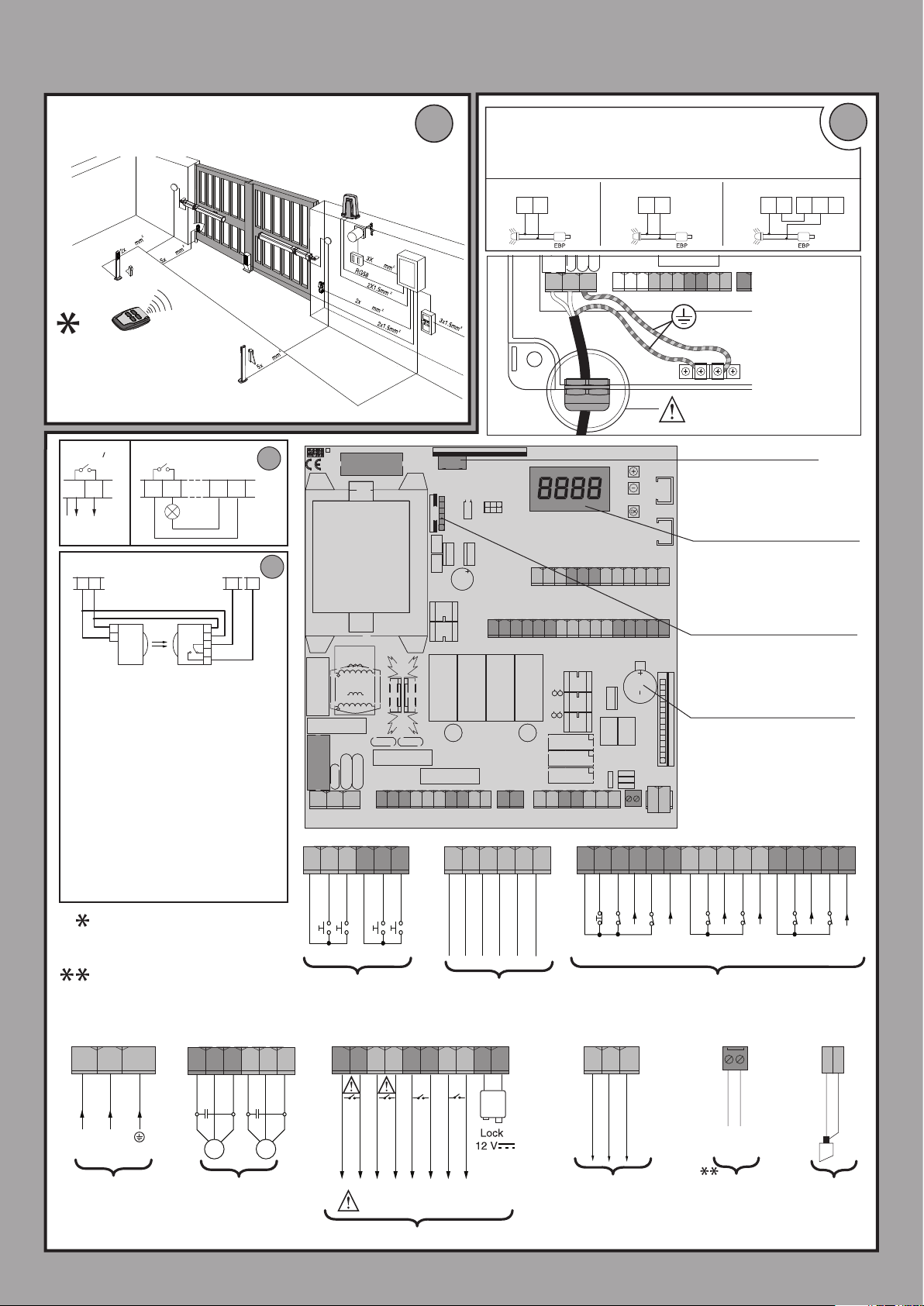
INSTALLAZIONE VELOCE-QUICK INSTALLATION-INSTALLATION RAPIDE
60 61 62 63 64 65 40 41 42 43
70 71 72 73 74 75 76 77 78 79 80 81 82
26 27 28 29 50 51 52
NTC
25
6.3 A/F 230V
10 A/F 110V
SCHNELLINSTALLATION-INSTALACIÓN RÁPIDA - SNELLE INSTALLATIE
PREDISPOSIZIONE TUBI, TUBE ARRANGEMENT,
PRÉDISPOSITION DES TUYAUX, VORBEREITUNG DER LEITUNGEN,
DISPOSICIÓN DE TUBOS, VOORBEREIDING LEIDINGEN.
*
2
3x2,5 mm
0,75
0,75
Vedere specica motore
See motor specications
Consultez les caractéristiques du moteur
Siehe Motordaten
Véase especicaciones motor
Zie motorspecicatie
AUX 3 = 1AUX 3 = 1
26
27
24V ~
Collegamento di 1 coppia di fotocellule non
vericate, per fotocellule vericate vedere
pagine seguenti.
Connection of 1 couple of untested photocells, for tested photocells see the following
pages.
Connexion d’une paire de photocellules non
vériées, pour les photocellules vériées
consultez les pages suivantes.
Anschluss von einem Paar nicht überprüfter
Fotozellen, für überprüfte Fotozelle siehe die
folgenden Seiten.
Conexión de 1 par de fotocélulas no comprobadas, para fotocélulas comproabdas véanse
las siguientes páginas.
Aansluiting van 1 paar niet-geverieerde
fotocellen. Raadpleeg de volgende pagina’s
voor geverieerde fotocellen.
26 27 50 51
SAFE 1 = 0
1
TX1
2
SCA
RX1
24 V~
1
2
3
4
5
0,75
1
C
725150 70
*
2
0,75
3x2,5 mm
0,75
315 m A/T 230V
F1
630 m A/T 110V
10 A/F 110V
6.3 A/F 230V
F2
GND
L N
10 11 12 14 15 16 20 21 22 23 26 27 28 29 50 51 52
60 61 62 63 6465
COM
IC 1
IC 2
COM
IC 3
IC 4
A
40 41 42 43
- REF SWE
Collegamento Elettroserratura EBP 230V. Congurazione AUX= Lampeggiante
EBP solenoid lock connection 230V. AUX conguration = Flashing
Connexion serrure électrique EBP 230V. Conguration AUX= Clignotant
Anschluss Elektroschloss EBP 230 V. Kongurierung AUX= Blinkleuchte
Conexión Cerradura eléctrica EBP 230V. Conguración AUX= Parpadeante
Verbinding Elektrisch slot EBP 230V. Conguratie AUX= Knipperend
AUX 0
20 21
F2
L N
GND
AUX 1
22 23
10 11 12 14 15 16 20 21 22 23
24
obbligatorio - compulsory
obligatoire - obligatorisch
obligatorio - verplicht
Connettore scheda opzionale
Optional board connector
Connecteur carte facultative
Steckverbinder Zusatzkarte
Conector de la tarjeta opcional
Connector optionele kaart
Display + tasti programmazione
Display + programming keys
60 61 62 63 64 65 40 41 42 43 44 45
70 71 72 73 74 75 76 77 78 79 80 81 82 8384 85
24 25
+ REF SWE
SWC 1
44 45
SWO 1
SWC2
70 71 72 73 7475 76 77 78 79 80 81 82 8384 85
SWO2
COM
STOP
NTC
SAFE 1
FAULT 1
Acheur + touches programmation
Display + Programmierungstasten
Pantalla + botones programación
Display + programmeringstoetsen
Connettore programmatore palmare
Palmtop programmer connector
Connecteur programmateur de poche
Steckverbinder Palmtop-Programmierer
Conector del programador de bolsillo
Connector programmeerbare palmtop
Batteria Litio 3V CR 1220
Lithium battery 3V CR 1220
Batterie Lithium 3V CR 1220
Lithiumbatterie 3 V CR 1220
Batería de Litio 3V CR 1220
Lithiumbatterij 3V CR 1220
Y
#
SAFE 2
FAULT 2
COM
SAFE 3
SAFE 4
FAULT 3
24 25
FAULT 4
COM
AUX 2
L
SAFE 5
GND
N
SAFE 6
FAULT 5
B
D812865 00100_04
FAULT 6
L N GND
L
220-230V ~
Alimentazione
Power supply
Alimentation
Stromversorgung
Alimentación
Voeding
14 - RIGEL 6
Altre tensioni disponibili a richiesta
Other voltages available on request
Autres tensions disponibles sur demande
Weitere Spannungen auf Anfrage erhältlich
Otras tensiones disponibles a petición
Andere spanningen op aanvraag beschikbaar
Non in dotazione
Not supplied
Ne sont pas fournis
Nicht im lieferum
No asignadas en el equipamiento base
Niet meegeleverd
10 11 12 14 15 16
N
*
M1 M2
Motore
Motor
moteu
Motor
Eindaansla
Motor
NO
NO
Commands
Commandes
Bedienelemente
Commando’s
NO
Comandi
Mandos
20 21 22 23
220
220
( 80W MAX )
230V
230V
AUX 0 - 220-230V
(80W MAX )
~
AUX0+AUX1+AUX2=80W MAX
NO
Entrées des ns de course
Entradas nales de carrera
26 27 28 29
24 25
AUX 2
(MAX 220-230V - 80W)
AUX 1 - 220-230V
~
AUX
Ingressi necorsa
limit switch inputs
Eingänge Anschlag
Ingangen
AUX 3
(MAX 24V - 10W)
(MAX 10W)
NC
NC
NC
Sicherheitsvorrichtungen
Dispositivos de seguridad
50 51 52
24V +
24 VSafe+
24V -
Alimentazione accessori
Accessories power supply
Alimentation des accessoires
Stromversorgung Zubehör
Alimentación accesorios
Voeding accessoires
NC
NC
Sicurezze
Safety devices
Sécurités
Veiligheden
NTC
NTH5D223KA
Sonda temperatura
Temperature sensor
Sonde température
Temperaturfühler
Sonda de temperatura
Temperatuursonde
NC
NC
Y
#
ANT
Antenna
Antenne
Antena
Antenne
SHIELD
ANT.
Page 15
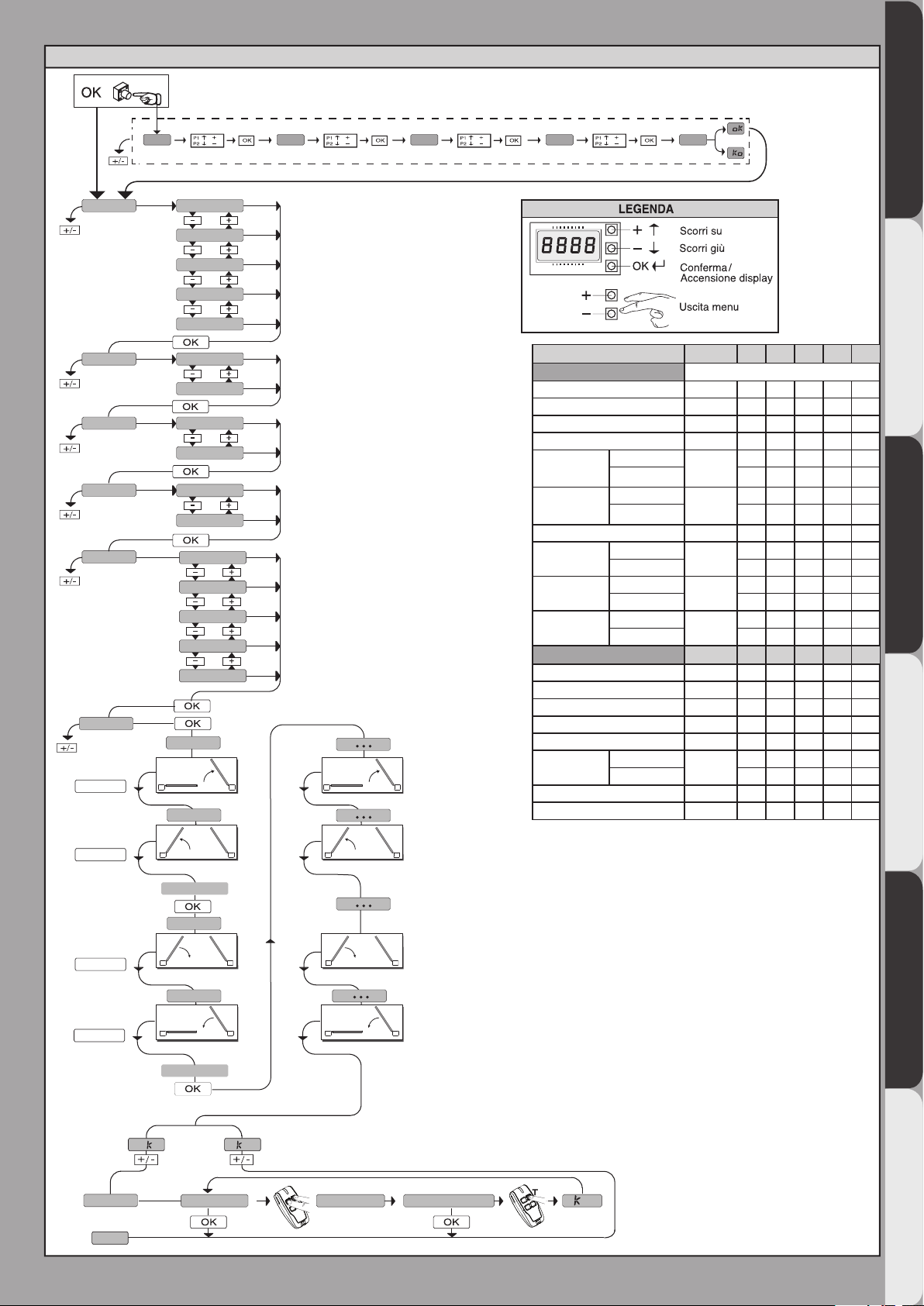
D812865 00100_04
***
x1
0---
10--
MENU SEMPLIFICATO
*** Inserimento password.
Richiesta con logica Livello Protezione impostata a 1, 2, 3, 4
150- 1520 ok
lang
tipo idr
n. mot.
Dir
preset
autoset
SWO/OK
2 1
m1.o
m2.o
ITA
fra
deu
eng
esp
elet
2
1
int
EXT
AR
sr
ac
sc
ind
: operatore idraulico
Idr
ELET:
operatore elettromeccanico
: apertura verso l’interno
INT
: apertura verso l’esterno
EXT
ar
: funzionamento automatico, residenziale
sr
: funzionamento semi-aut., residenziale
ac
: funzionamento automatico, condominiale
Sc
: funzionamento semi-automatico, condominiale
Ind
: funzionamento a uomo presente
2 1
PRESET DEFAULT
PARAMETRI
Tempo di lavoro Motore 1 60.0 20.0 20.0 20.0 20.0 20.0
Tempo di lavoro Motore 2 60.0 20.0 20.0 20.0 20.0 20.0
Tempo sfasamento apertura 3 2 2 2 2 2
Tempo sfasamento chiusura 3 2 2 2 2 2
Tempo di
rallentamento
motore 1
Tempo di
rallentamento
motore 2
TCA 40 20 40 30 40 40
Forza apertura
Forza chiusura
Forza
rallentamento
TCA 0 1 0 1 0 0
Movimento passo passo 0 1 0 1 0 0
Preallarme 0 0 0 1 1 0
Uomo presente 0 0 0 0 0 1
Blocca impulsi in apertura 0 0 0 1 1 0
Mantenimento
blocco
SAFE1 0 4 4 4 4 0
Livello Protezione 0 0 0 0 0 2
idraulico
elettromeccanico
idraulico
elettromeccanico
idraulico
elettromeccanico
idraulico
elettromeccanico
idraulico
elettromeccanico
LOGICHE DEFAULT
idraulico
elettromeccanico
AR SR AC SC ind
0 0 0 0 0
0
3 3 3 3 3
0 0 0 0 0
0
3 3 3 3 3
99 99 99 99 99
50
50 50 50 50 50
99 99 99 99 99
50
50 50 50 50 50
99 99 99 99 99
50
50 50 50 50 50
AR SR AC SC ind
1 1 1 1 1
0
0 0 0 0 0
ENGLISH FRANÇAIS ESPAÑOL
DEUTSCHITALIANO
SWO/OK
SWC/OK
SWC/OK
mem.telec
fine
2 1
close
2 1
2 1
open
o
m2.c
m1.c
o
tasto nascosto
2 1
2 1
2 1
rilascia
tasto desiderato
NEDERLANDS
O 01
RIGEL 6 - 15
Page 16
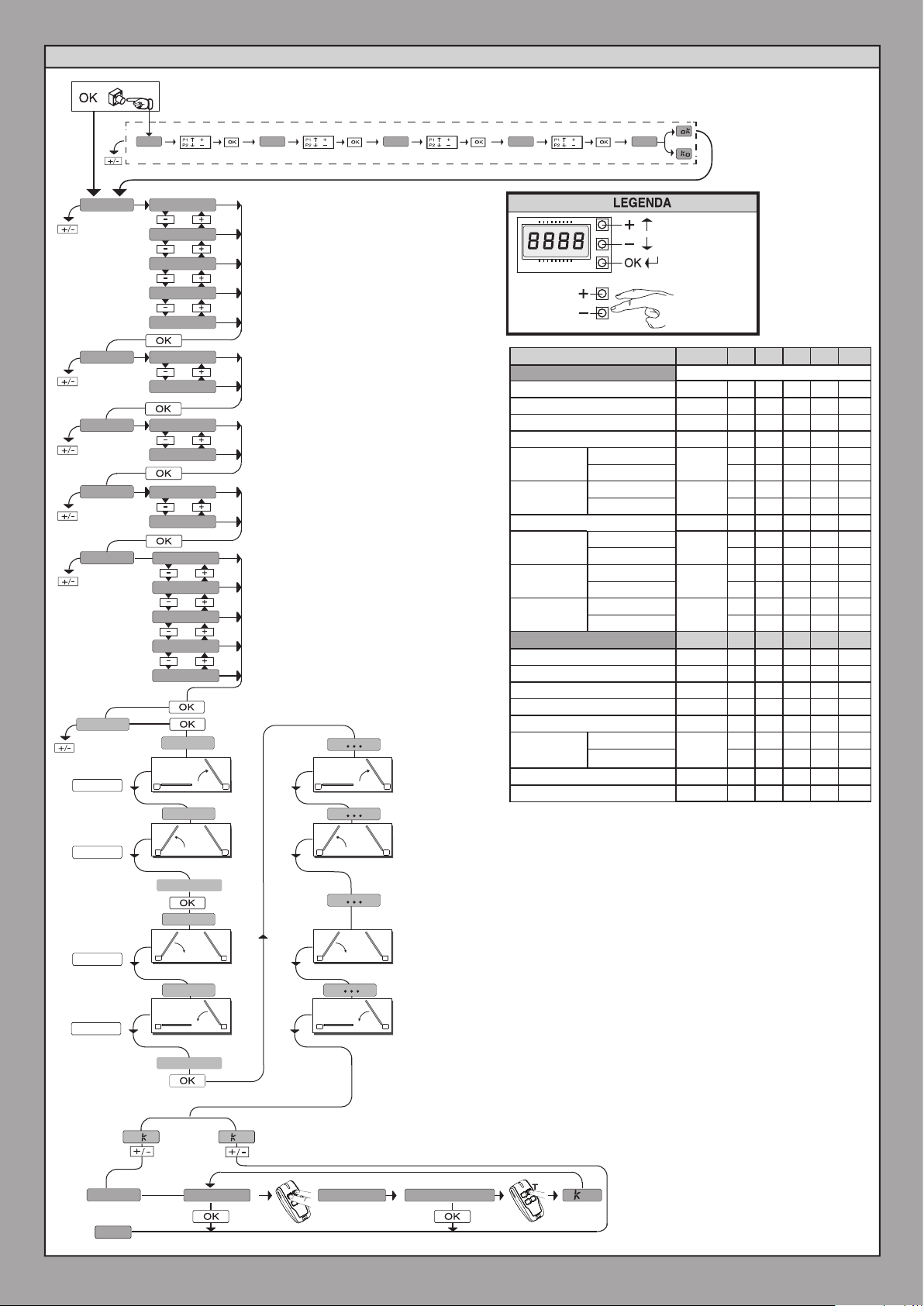
***
x1
0---
10--
SIMPLIFIED MENU
*** Password entry.
Request with Protection Level logic set to 1, 2, 3, 4
D812865 00100_04
150- 1520 ok
language
ITA
fra
deu
eng
esp
type hydr hydr: hydraulic operator
: electromechanical operator
n. mot.
elec elec
2
1
: inward opening
Dir
preset
int
EXT
AR
sr
ac
sc
ind
INT
: outward opening
EXT
ar: automatic operation, residential
sr: semiautomatic operation, residential
ac: automatic operation, commercial
Sc:
semiautomatic operation, commercial
Ind: dead man operation
autoset
m1.o
SWO/OK
2 1
2 1
m2.o
Scroll up
Scroll down
Conrm/Switch
on display
Exit Menù
PRESET DEFAULT
PARAMETER
Operation time motor 1
Operation time motor 2
Time lag opening 3 2 2 2 2 2
Time lag closing 3 2 2 2 2 2
Motor 1
slow-down time
Motor 2
slow-down time
TCA
Opening force
Closing force
Slow-down force
TCA
Step-by-step movement 0 1 0 1 0 0
Pre alarm
Hold-to-run
Impulse lock on opening
Lock hold
SAFE 1
Protection level
hydraulic
electromechanical
hydraulic
electromechanical
hydraulic
electromechanical
hydraulic
electromechanical
hydraulic
electromechanical
LOGIC DEFAULT
hydraulic
electromechanical
AR SR AC SC ind
60.0 20.0 20.0 20.0 20.0 20.0
60.0 20.0 20.0 20.0 20.0 20.0
0 0 0 0 0
0
3 3 3 3 3
0 0 0 0 0
0
3 3 3 3 3
40 20 40 30 40 40
99 99 99 99 99
50
50 50 50 50 50
99 99 99 99 99
50
50 50 50 50 50
99 99 99 99 99
50
50 50 50 50 50
AR SR AC SC ind
0 1 0 1 0 0
0 0 0 1 1 0
0 0 0 0 0 1
0 0 0 1 1 0
1 1 1 1 1
0
0 0 0 0 0
0 4 4 4 4 0
0 0 0 0 0 2
SWO/OK
SWC/OK
SWC/OK
mem.remotes
16 - RIGEL 6
end
2 1
2 1
2 1
o
close
m2.c
m1.c
open
o
hidden button
2 1
2 1
2 1
release
desidered button
O 01
Page 17
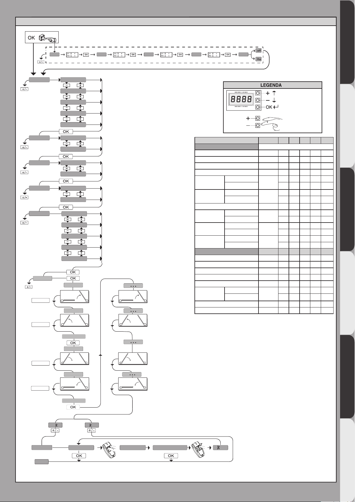
MENU SIMPLIFIÉ
D812865 00100_04
lang
type hydr
n. mot.
Dir
preset
autoset
SWO/OK
***
x1
0---
ITA
fra
deu
eng
esp
elec
2
1
int
EXT
AR
sr
ac
sc
ind
m1.o
2 1
m2.o
10--
: Actionneur hydraulique
hydr
150- 1520 ok
ELEc:Actionneur électromécanique
: ouverture vers l’intérieur
INT
: ouverture vers l’extérieur
EXT
ar : fonctionnement automatique, résidentiel
sr : fonctionnement semi-automatique, résidentiel
ac : fonctionnement automatique, collectif
fonctionnement semi-automatique, collectif
Sc :
Ind : fonctionnement à homme présent
2 1
Demande avec logique Niveau Protection congurée sur
*** Saisie du mot de passe.
1, 2, 3, 4
Monter
Descendre
Confirmation /
allumage afficheur
Sortir du menu
PRESET DEFAULT
PARAMÈTRES
Temps de travail moteur 1
Temps de travail moteur 2
Temps déphasage ouverture 3 2 2 2 2 2
Temps déphasage fermeture 3 2 2 2 2 2
Temps
ralentissement
moteur 1
Temps
ralentissement
moteur 2
TCA
Force ouverture
Force fermeture
Force
ralentissement
TCA
Force ralentissement 0 1 0 1 0 0
Préalarme
Homme présent
Blocage des Impulsions d’ouverture
Maintient du
blocage
SAFE 1
Niveau de protection
hydraulique
electromecanique
hydraulique
electromecanique
hydraulique
electromecanique
hydraulique
electromecanique
hydraulique
electromecanique
LOGIQUES
hydraulique
electromecanique
DEFAULT
AR SR AC SC ind
60.0 20.0 20.0 20.0 20.0 20.0
60.0 20.0 20.0 20.0 20.0 20.0
0 0 0 0 0
0
3 3 3 3 3
0 0 0 0 0
0
3 3 3 3 3
40 20 40 30 40 40
99 99 99 99 99
50
50 50 50 50 50
99 99 99 99 99
50
50 50 50 50 50
99 99 99 99 99
50
50 50 50 50 50
AR SR AC SC ind
0 1 0 1 0 0
0 0 0 1 1 0
0 0 0 0 0 1
0 0 0 1 1 0
1 1 1 1 1
0
0 0 0 0 0
0 4 4 4 4 0
0 0 0 0 0 2
ENGLISH FRANÇAIS ESPAÑOL
DEUTSCHITALIANO
SWO/OK
SWC/OK
SWC/OK
mem.telec
fin
2 1
2 1
2 1
o
close
m2.c
m1.c
open
o
touche cachee
2 1
2 1
2 1
relacher
touche desiree
NEDERLANDS
O 01
RIGEL 6 - 17
Page 18

MENÚ SEMPLIFICADO
lang
Dir
ITA
fra
deu
eng
esp
int
INT
EXT
ar : funcionamiento automático, en viviendas
sr : funcionamiento semi-aut, en viviendas
ac : funcionamiento automático, en edicios
Sc : funcionamiento semi-aut, en edicios
Ind: funcionamiento con hombre presente
: apertura hacia dentro
EXT
: apertura hacia afuera
TIPO hidr
elec
2
O 01
tecla deseada
anad start
suelte
RADIOM
FIN
o
o
n. mot.
1
hIdr
: Operador hidráulico
ELET: Operador electromecánico
x1
0---
10--
150- 1520 ok
autoset
2 1
2 1
2 1
2 1
close
open
SWO/OK
SWO/OK
SWC/OK
SWC/OK
m2.o
m1.o
2 1
2 1
2 1
2 1
m2.c
m1.c
Desplazar hacia arriba
Desplazar hacia abajo
Conrmación/
Encendido pantalla
Retorno al menú
principal
LEYENDA
AR
preset
sr
ac
sc
ind
VEREINFACHTES MENÜ
x1
***
0---
lang
type
n. mot.
Dir
preset
autoset
SWO/OK
SWO/OK
m1.o
2 1
m2.o
2 1
ITA
fra
deu
eng
esp
hydr
elec
2
1
int
EXT
AR
sr
ac
sc
ind
10--
: Hydrauliktrieb
hydr
ELEc:elektromechanischer Trieb
: Önung nach innen
INT
: Önung nach außen
EXT
ar : Automatikbetrieb, Wohnbereich
sr : Halbautomatikbetrieb, Wohnbereich
ac : Automatikbetrieb, Hausbereich
Sc : Halbautomatikbetrieb, Hausbereich
Ind : Halbautomatikbetrieb, Hausbereich
2 1
2 1
150- 1520 ok
Anforderung mit Schutzniveaulogik eingestellt auf 1, 2, 3 oder 4
*** Passwordeingabe
Aufwärts
Abwärts
Bestätigung/
Aufleuchten Display
Zurück zum
Hauptmenü
PRESET DEFAULT
PARAMETER
Arbeitszeit für motor 1 60.0 20.0 20.0 20.0 20.0 20.0
Arbeitszeit für motor 2 60.0 20.0 20.0 20.0 20.0 20.0
Verschiebungszeit Önung 3 2 2 2 2 2
Verschiebungszeit Schließung 3 2 2 2 2 2
Verlangsamungszeit
Motor 1
Verlangsamungszeit
Motor 2
TCA 40 20 40 30 40 40
Kraft Önung
Kraft Schließung
Verlangsamungskraft
TCA 0 1 0 1 0 0
Einzelschrittbewegung 0 1 0 1 0 0
Voralarm 0 0 0 1 1 0
Totmann-Funktion 0 0 0 0 0 1
Impulssperre bei der Önung 0 0 0 1 1 0
Aufrechterhalten
der Sperre
SAFE1 0 4 4 4 4 0
Schutzniveau 0 0 0 0 0 2
hydraulischer
elektromechanischer 3 3 3 3 3
hydraulischer
elektromechanischer 3 3 3 3 3
hydraulischer
elektromechanischer 50 50 50 50 50
hydraulischer
elektromechanischer 50 50 50 50 50
hydraulischer
elektromechanischer 50 50 50 50 50
LOGIC DEFAULT
hydraulischer
elektromechanischer 0 0 0 0 0
AR SR AC SC ind
0 0 0 0 0
0
0 0 0 0 0
0
99 99 99 99 99
50
99 99 99 99 99
50
99 99 99 99 99
50
AR SR AC SC ind
1 1 1 1 1
0
D812865 00100_04
SWC/OK
SWC/OK
speichern hs
ende
18 - RIGEL 6
2 1
2 1
o
close
m2.c
m1.c
open
verst. taste
o
2 1
2 1
loslassen
gevue. taste
O 01
Page 19
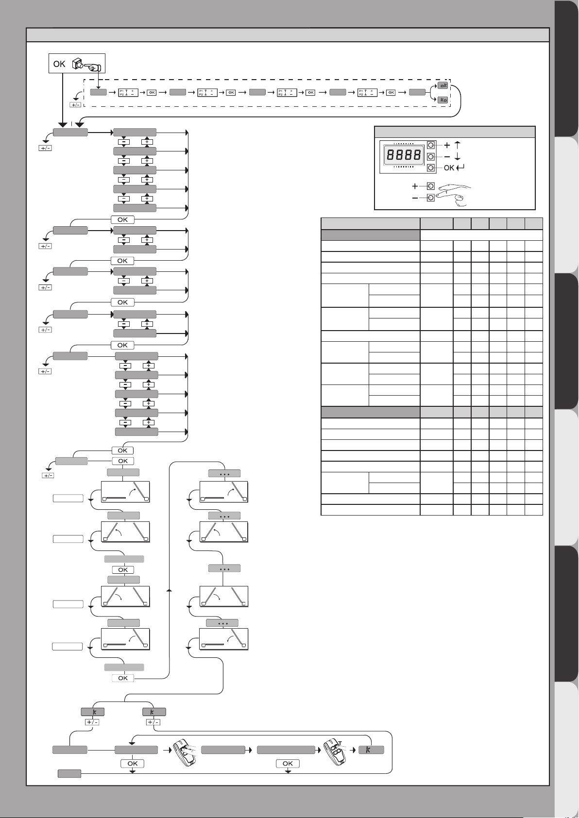
MENÚ SEMPLIFICADO
D812865 00100_04
lang
n. mot.
preset
autoset
SWO/OK
x1
***
0---
ITA
fra
deu
eng
esp
TIPO hidr
elec
2
1
Dir
int
EXT
AR
sr
ac
sc
ind
m1.o
2 1
m2.o
10--
hIdr
: Operador hidráulico
ELET: Operador electromecánico
: apertura hacia dentro
INT
: apertura hacia afuera
EXT
ar : funcionamiento automático, en viviendas
sr : funcionamiento semi-aut, en viviendas
ac : funcionamiento automático, en edicios
Sc : funcionamiento semi-aut, en edicios
150- 1520 ok
Ind: funcionamiento con hombre presente
2 1
Solicitud con lógica Nivel Protección congurada a 1, 2, 3, 4
*** Introducción contraseña.
LEYENDA
Desplazar hacia arriba
Desplazar hacia abajo
Conrmación/
Encendido pantalla
Retorno al menú
principal
PRESET DEFAULT
PARAMETROS
Tiempo de trabajo motor 1 60.0 20.0 20.0 20.0 20.0 20.0
Tiempo de trabajo motor 2 60.0 20.0 20.0 20.0 20.0 20.0
Tiempo desfasaje apertura 3 2 2 2 2 2
Tiempo desfasaje cierre 3 2 2 2 2 2
Tiempo de
deceleración
motor 1
Tiempo de
deceleración
motor 2
TCA 40 20 40 30 40 40
Fuerza de
apertura
Fuerza de cierre
Fuerza
deceleración
TCA 0 1 0 1 0 0
Movimiento paso a paso 0 1 0 1 0 0
Pre alarma 0 0 0 1 1 0
Hombre Presente 0 0 0 0 0 1
Bloquea impulsos en fase de apertura 0 0 0 1 1 0
Mantenimiento
del bloqueo
SAFE1 0 4 4 4 4 0
Nivel Protección 0 0 0 0 0 2
hidráulico
electromecánico
hidráulico
electromecánico
hidráulico
electromecánico
hidráulico
electromecánico
hidráulico
electromecánico
LOGICA
hidráulico
electromecánico
DEFAULT
AR SR AC SC ind
0 0 0 0 0
0
3 3 3 3 3
0 0 0 0 0
0
3 3 3 3 3
99 99 99 99 99
50
50 50 50 50 50
99 99 99 99 99
50
50 50 50 50 50
99 99 99 99 99
50
50 50 50 50 50
AR SR AC SC ind
1 1 1 1 1
0
0 0 0 0 0
ENGLISH FRANÇAIS ESPAÑOL
DEUTSCHITALIANO
SWO/OK
SWC/OK
SWC/OK
RADIOM
FIN
2 1
2 1
2 1
o
close
m2.c
m1.c
open
anad start
o
2 1
2 1
2 1
suelte
tecla deseada
NEDERLANDS
O 01
RIGEL 6 - 19
Page 20
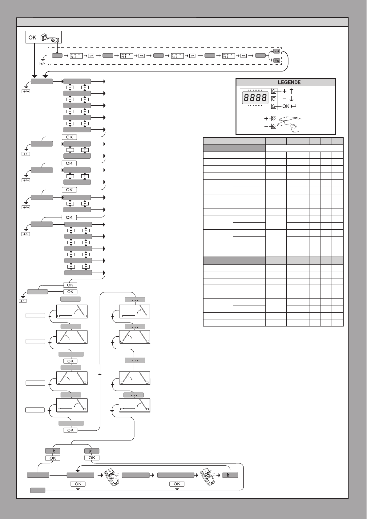
VEREENVOUDIGD MENU
x1
***
0---
lang
type hydr
n. mot.
Dir
preset
autoset
SWO/OK
2 1
m1.o
m2.o
ITA
fra
deu
eng
esp
elec
2
1
int
EXT
AR
sr
ac
sc
ind
10--
hydr:
Hydraulische automatisering
ELET: Elektromechanische automatisering
: opening naar binnen
INT
: opening naar buiten
EXT
: automatische werking, residentieel
ar
: semi-automatische werking, residentieel
sr
: automatische werking, gemeenschappelijk
ac
semi-automatische werking, gemeenschappelijk
:
Sc
: werking bij aanwezige persoon
Ind
2 1
150- 1520 ok
Aanvraag met logica Beschermingsniveau ingesteld op 1, 2, 3, 4
*** Password invoeren.
Doorloop op
Doorloop neer
Bevestig /
Aanschakeling
display
Terugkeer naar
het hoofdmenu
PRESET DEFAULT
PARAMETERS
Werktijd motor 1 60.0 20.0 20.0 20.0 20.0 20.0
Werktijd motor 2 60.0 20.0 20.0 20.0 20.0 20.0
Tijd van faseverschil opening 3 2 2 2 2 2
Tijd van faseverschil sluiting 3 2 2 2 2 2
Tijd van
afremming
motor 1
Tijd van
afremming
motor 2
TCA 40 20 40 30 40 40
Openingskracht
Sluitkracht
Afremmingskracht
TCA 0 1 0 1 0 0
Stap-voor-stap beweging 0 1 0 1 0 0
Pre-alarm
Persoon Aanwezig
Blokkeert impulsen bij opening
Handhaving
blokkering
SAFE1 0 4 4 4 4 0
Beschermingsniveau 0 0 0 0 0 2
hydraulische
elektromechanische
hydraulische
elektromechanische
hydraulische
elektromechanische
hydraulische
elektromechanische
hydraulische
elektromechanische
LOGICA
hydraulische
elektromechanische
DEFAULT
AR SR AC SC ind
0 0 0 0 0
0
3 3 3 3 3
0 0 0 0 0
0
3 3 3 3 3
99 99 99 99 99
50
50 50 50 50 50
99 99 99 99 99
50
50 50 50 50 50
99 99 99 99 99
50
50 50 50 50 50
AR SR AC SC ind
0 0 0 1 1 0
0 0 0 0 0 1
0 0 0 1 1 0
1 1 1 1 1
0
0 0 0 0 0
D812865 00100_04
SWO/OK
SWC/OK
SWC/OK
mem.remotes
end
20 - RIGEL 6
2 1
2 1
2 1
o
close
m2.c
m1.c
open
o
hidden button
2 1
2 1
2 1
release
desidered button
O 01
Page 21

D812865 00100_04
1)
AUTOCONFIGURATION POUR MOTEURS AVEC FIN DE COURSE / AUTOSET FÜR MOTOREN MIT ENDSCHALTER
AUTOSET PER MOTORI CON FINECORSA / AUTOSET FOR MOTORS WITH LIMIT SWITCHES
AUTOSET PARA MOTORES CON FINAL DE CARRERA / AUTOSET VOOR MOTOREN MET EINDAANSLAGEN
SWC1 + SWC2
Chiuso - Closed
Fermé - Geschlossenem
Cerrada - Gesloten
2)
autoset
S1
S2
S3
D1
3)
5)
7)
9)
m1.O
m2.O
close
m2.c
m1.c
S1
S2
S3
S1
S2
S3
S1
S2
S3
S1
S2
S3
M1 M2
M1 M2
M1 M2
M1 M2
Apertura M1
Opening M1
Ouverture M1
Önung M1
Apertura M1
Openings M1
Apertura M2
Opening M2
Ouverture M2
Önung M2
Apertura M2
Openings M2
Chiusura M2
Closing M2
Fermeture M2
Schließung M2
Cierre M2
Sluitings M2
Chiusura M1
Closing M1
Fermeture M1
Schließung M1
Cierre M1
Sluitings M1
4)
6)
8)
10)
M1
SWO1
M1 M2
M1 M2
M1 M2
SWC1
M2
ENGLISH FRANÇAIS ESPAÑOL
SWO2
SWC2
11)
13)
15)
17)
open
. . .
. . .
. . .
. . .
M1 M2
S1
S2
S3
S1
S2
S3
M1 M2
S1
S2
S1
S2
S3
M1 M2
Apertura M1
Opening M1
Ouverture M1
Önung M1
Apertura M1
Openings M1
Apertura M2
Opening M2
Ouverture M2
Önung M2
Apertura M2
Openings M2
Chiusura M2
Closing M2
Fermeture M2
Schließung M2
Cierre M2
Sluitings M2
Chiusura M1
Closing M1
Fermeture M1
Schließung M1
Cierre M1
Sluitings M1
12)
14)
16)
18)
M1
SWO1
M1 M2M1 M2
M1 M2
M1 M2
SWC1
M2
SWO2
SWC2
DEUTSCHITALIANO
NEDERLANDS
19)
1)
S1
S2
S3
S1
S2
S3
SWC1 + SWC2
RIGEL 6 - 21
Page 22
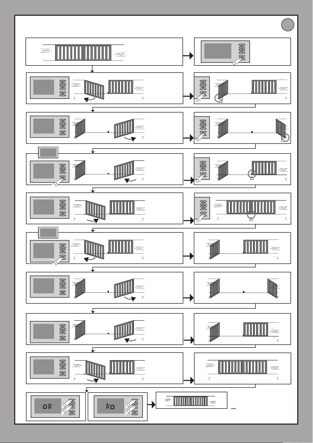
AUTOSET PER MOTORI SPROVVISTI DI FINECORSA / AUTOSET FOR MOTORS WITH NO LIMIT SWITCHES
AUTOCONFIGURATION POUR MOTEURS SANS FIN DE COURSE / AUTOSET FÜR MOTOREN OHNE ENDSCHALTER
AUTOSET PARA MOTORES SIN FINAL DE CARRERA / AUTOSET VOOR MOTOREN ZONDER EINDAANSLAGEN
1)
Chiuso - Closed
Fermé - Geschlossenem
Cerrada - Gesloten
2)
autoset
D2
D812865 00100_04
S1
S2
S3
3)
5)
7)
9)
m1.O
m2.O
close
m2.c
m1.c
S1
S2
S3
S1
S2
S3
M1 M2
S1
S2
S3
M1 M2
S1
S2
S3
M1 M2
Apertura M1
Opening M1
Ouverture M1
Önung M1
Apertura M1
Openings M1
Apertura M2
Opening M2
Ouverture M2
Önung M2
Apertura M2
Openings M2
Chiusura M2
Closing M2
Fermeture M2
Schließung M2
Cierre M2
Sluitings M2
Chiusura M1
Closing M1
Fermeture M1
Schließung M1
Cierre M1
Sluitings M1
4)
6)
8)
10)
S1
M1
S2
S3
M1 M2M1 M2
S1
S2
S3
M1 M2
S1
S2
S3
M1 M2
S1
S2
S3
M2
11)
13)
15)
17)
open
. . .
. . .
. . .
. . .
M1 M2
S1
S2
S3
S1
S2
S3
M1 M2
S1
S2
S3
S1
S2
S3
M1 M2
Apertura M1
Opening M1
Ouverture M1
Önung M1
Apertura M1
Openings M1
Apertura M2
Opening M2
Ouverture M2
Önung M2
Apertura M2
Openings M2
Chiusura M2
Closing M2
Fermeture M2
Schließung M2
Cierre M2
Sluitings M2
Chiusura M1
Closing M1
Fermeture M1
Schließung M1
Cierre M1
Sluitings M1
12)
14)
16)
18)
M1
M1 M2M1 M2
M1 M2
M1 M2
M2
19)
22 - RIGEL 6
1)
S1
S2
S3
S1
S2
S3
Page 23
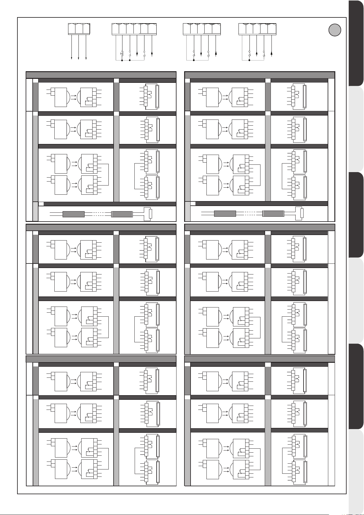
D812865 00100_04
50
70
71
73
74 75
24V -
24V +
24 VSafe+
COM
SAFE 1
SAFE 2
STOP
FAULT 1
FAULT 2
NC
NC
NC
SAFE 5
SAFE 5
SAFE 5
SAFE2
52
51
50
24V +
24 VSafe+
24V -
72
71
70
STOP
COM
73
SAFE 1
74 75
SAFE 2
FAULT 1
FAULT 2
77
76
COM
78
SAFE 3
79 80
SAFE 4
FAULT 3
FAULT 4
82
81
COM
83
SAFE 5
84 85
FAULT 5
SAFE 6
FAULT 6
E
1
51
50
TEST OFFTEST ONTEST OFFTEST ON
SAFE1 = 0,2,4
2
52
50
52
50
SAFE1 = 1,3,5
52
50
5
SAFE1 = 8,11,14
1
51
50
SAFE3 = 0,2,4
2
52
50
52
50
SAFE3 = 1,3,5
52
50
1 PHOT / 1 PHOT OP / 1 PHOT CL
1
1
TX1 RX1
TX1 RX1
2
2
1 PHOT / 1 PHOT OP / 1 PHOT CL
1
1
TX1 RX1
TX1 RX1
2
2
2 PHOT / 2 PHOT OP / 2 PHOT CL
1
1
TX1 RX1
TX1 RX1
2
2
1
1
TX2 RX2
TX2 RX2
2
2
SAFETY EDGE
70
72
1 PHOT / 1 PHOT OP / 1 PHOT CL
1
1
TX1 RX1
TX1 RX1
2
2
1 PHOT / 1 PHOT OP / 1 PHOT CL
1
1
TX1 RX1
TX1 RX1
2
2
2 PHOT / 2 PHOT OP / 2 PHOT CL
1
1
TX1 RX1
TX1 RX1
2
2
1
1
TX2 RX2
TX2 RX2
2
2
NC
SAFE 1
3
1
1
51
50
70
72
SAFE1 = 6,9,12
2
2
3
3
4
4
5
5
4
1
1
51
2
2
50
3
3
70
4
4
73
5
5
72
51
1
1
2
2
50
70
72
51
50
73
70
SAFE1 = 7,10,13
SAFETY EDGE
3
3
4
4
5
5
1
1
2
2
3
3
4
4
5
5
BAR 8K2 / BAR 8K2 OP / BAR 8K2 CL
SAFE 3
3
1
1
51
2
2
50
3
3
76
4
4
5
5
77
SAFE3 = 6,9,12
4
1
1
51
2
2
50
3
3
76
4
4
78
5
5
77
51
1
1
2
2
3
3
4
4
5
5
1
1
2
2
3
3
4
4
5
5
50
76
77
51
50
78
76
SAFE3 = 7,10,13
NC
NC
1 BAR / 1 BAR OP / 1 BAR CL
51
6
6
72
5
5
4
4
70
3
3
2
2
50
51
Bar 1
Bar 1
1
1
1 BAR / 1 BAR OP / 1 BAR CL
52
6
6
72
5
5
73
4
4
70
3
3
2
2
50
51
Bar 1
Bar 1
1
1
2 BAR / 2 BAR OP / 2 BAR CL
52
6
6
72
5
5
70
4
4
3
3
2
2
50
51
Bar 1
Bar 1
1
1
52
6
6
70
5
5
73
4
4
3
3
2
2
50
51
Bar 2
Bar 2
1
1
8,2Kohm 5%
1 BAR / 1 BAR OP / 1 BAR CL
51
6
6
77
5
5
4
4
76
3
3
2
2
50
51
Bar 1
Bar 1
1
1
1 BAR / 1 BAR OP / 1 BAR CL
52
6
6
77
5
5
78
4
4
76
3
3
2
2
50
51
Bar 1
Bar 1
1
1
2 BAR / 2 BAR OP / 2 BAR CL 2 BAR / 2 BAR OP / 2 BAR CL
52
6
6
77
5
5
76
4
4
3
3
2
2
50
51
Bar 1
Bar 1
1
1
52
6
6
76
5
5
78
4
4
3
3
2
2
50
51
Bar 2
Bar 2
1
1
1
SAFE2 = 0,2,4
2
SAFE2 = 1,3,5
SAFE2 = 8,11,14
1
SAFE4 = 0,2,4
2
SAFE4 = 1,3,5
NC
NC
NC
NC
1 PHOT / 1 PHOT OP / 1 PHOT CL
51
1
1
TX1 RX1
TX1 RX1
2
2
50
1 PHOT / 1 PHOT OP / 1 PHOT CL
1
1
52
TX1 RX1
TX1 RX1
2
2
50
2 PHOT / 2 PHOT OP / 2 PHOT CL
1
1
52
TX1 RX1
TX1 RX1
2
2
50
52
1
1
TX2 RX2
TX2 RX2
50
2
2
5
51
50
52
50
52
50
52
50
SAFETY EDGE
70
74
1 PHOT / 1 PHOT OP / 1 PHOT CL
1
1
TX1 RX1
TX1 RX1
2
2
1 PHOT / 1 PHOT OP / 1 PHOT CL
1
1
TX1 RX1
TX1 RX1
2
2
2 PHOT / 2 PHOT OP / 2 PHOT CL
1
1
TX1 RX1
TX1 RX1
2
2
1
1
TX2 RX2
TX2 RX2
2
2
NC
NC
NC
NC
SAFE 2
3
1
1
51
2
2
50
3
3
70
4
4
5
5
74
SAFE2 = 6,9,12
4
1
1
51
2
2
50
3
3
70
4
4
75
5
5
74
51
1
1
2
2
50
70
74
51
50
75
70
SAFETY EDGE
SAFE 4
51
50
76
79
51
50
76
80
79
51
50
76
79
51
50
80
76
SAFE2= 7,10,13
3
SAFE4 = 6,9,12
4
SAFE4 = 7,10,13
3
3
4
4
5
5
1
1
2
2
3
3
4
4
5
5
BAR 8K2 / BAR 8K2 OP / BAR 8K2 CL
1
1
2
2
3
3
4
4
5
5
1
1
2
2
3
3
4
4
5
5
1
1
2
2
3
3
4
4
5
5
1
1
2
2
3
3
4
4
5
5
1 BAR / 1 BAR OP / 1 BAR CL
51
6
6
74
5
5
4
4
70
3
3
2
2
50
51
Bar 1
Bar 1
1
1
1 BAR / 1 BAR OP / 1 BAR CL
52
6
6
74
5
5
75
4
4
70
3
3
2
2
50
51
Bar 1
Bar 1
1
1
2 BAR / 2 BAR OP / 2 BAR CL
52
6
6
74
5
5
70
4
4
3
3
2
2
50
51
Bar 1
Bar 1
1
1
52
6
6
70
5
5
75
4
4
3
3
2
2
50
51
Bar 2
Bar 2
1
1
8,2Kohm 5%
1 BAR / 1 BAR OP / 1 BAR CL
51
6
6
79
5
5
4
4
76
3
3
2
2
50
51
Bar 1
Bar 1
1
1
1 BAR / 1 BAR OP / 1 BAR CL
52
6
6
79
5
5
80
4
4
76
3
3
2
2
50
51
Bar 1
Bar 1
1
1
52
6
6
79
5
5
76
4
4
3
3
2
2
50
51
Bar 1
Bar 1
1
1
52
6
6
76
5
5
80
4
4
3
3
2
2
50
51
Bar 2
Bar 2
1
1
TEST OFFTEST ON
TEST OFFTEST ONTEST OFFTEST ON
ENGLISH FRANÇAIS ESPAÑOL
DEUTSCHITALIANO
1
51
50
TEST OFFTEST ON
SAFE5 = 0,2,4
2
52
50
52
50
SAFE5 = 1,3,5
52
50
1 PHOT / 1 PHOT OP / 1 PHOT CL
1
1
TX1 RX1
TX1 RX1
2
2
1 PHOT / 1 PHOT OP / 1 PHOT CL
1
1
TX1 RX1
TX1 RX1
2
2
2 PHOT / 2 PHOT OP / 2 PHOT CL
1
1
TX1 RX1
TX1 RX1
2
2
1
1
TX2 RX2
TX2 RX2
2
2
SAFE 5
1
1
51
2
2
50
3
3
81
4
4
5
5
82
1
1
51
2
2
50
3
3
81
4
4
83
5
5
82
51
1
1
2
2
50
3
3
4
4
81
82
5
5
1
1
51
2
2
50
3
3
83
4
4
81
5
5
1 BAR / 1 BAR OP / 1 BAR CL
3
SAFE5 = 6,9,12
4
1 BAR / 1 BAR OP / 1 BAR CL
2 BAR / 2 BAR OP / 2 BAR CL
SAFE5 = 7,10,13
1 PHOT / 1 PHOT OP / 1 PHOT CL
1
51
6
6
82
5
5
4
4
81
3
3
2
2
50
51
Bar 1
Bar 1
1
1
52
6
6
82
5
5
83
4
4
81
3
3
2
2
50
51
Bar 1
Bar 1
1
1
52
6
6
82
5
5
81
4
4
3
3
2
2
50
51
Bar 1
Bar 1
1
1
52
6
6
81
5
5
83
4
4
3
3
2
2
50
51
Bar 2
Bar 2
1
1
51
1
1
2
2
50
SAFE6 = 0,2,4
1 PHOT / 1 PHOT OP / 1 PHOT CL
2
1
1
52
2
2
50
2 PHOT / 2 PHOT OP / 2 PHOT CL
1
1
52
2
2
50
SAFE6 = 1,3,5
52
1
1
50
2
2
TX1 RX1
TX1 RX1
TX1 RX1
TX1 RX1
TX1 RX1
TX1 RX1
TX2 RX2
TX2 RX2
SAFE 6
1
1
2
2
3
3
4
4
5
5
1
1
2
2
3
3
4
4
5
5
1
1
2
2
3
3
4
4
5
5
1
1
2
2
3
3
4
4
5
5
51
50
81
84
51
50
81
85
84
51
50
81
84
51
50
85
81
1 BAR / 1 BAR OP / 1 BAR CL
3
51
84
81
50
51
SAFE6 = 6,9,12
1 BAR / 1 BAR OP / 1 BAR CL
4
52
84
85
81
50
51
2 BAR / 2 BAR OP / 2 BAR CL
52
84
81
SAFE6 = 7,10,13
50
51
52
81
85
50
51
6
6
5
5
4
4
3
3
2
2
Bar 1
Bar 1
1
1
6
6
5
5
4
4
3
3
2
2
Bar 1
Bar 1
1
1
6
6
5
5
4
4
3
3
2
2
Bar 1
Bar 1
1
1
6
6
5
5
4
4
3
3
2
2
Bar 2
Bar 2
1
1
NEDERLANDS
RIGEL 6 - 23
Page 24
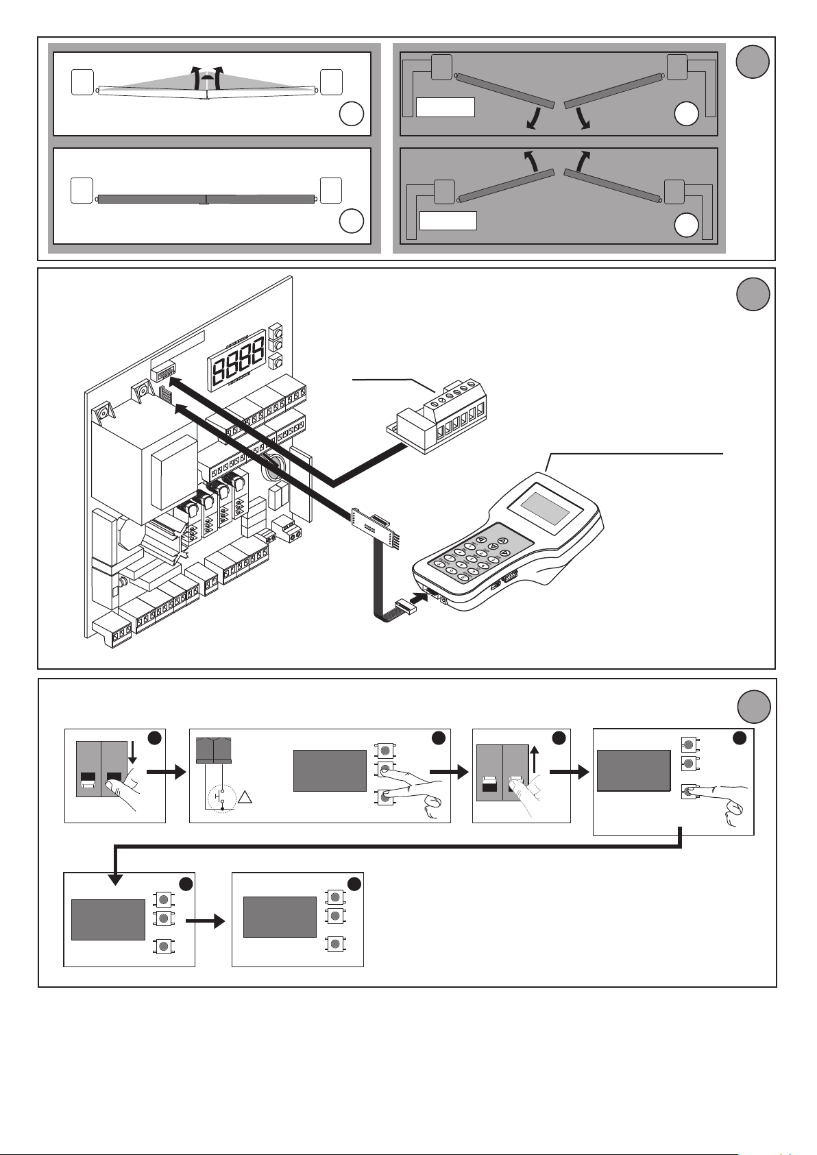
I
F
A
B
Scheda di espansione
Expansion board
Carte d’expansion
Erweiterungskarte
Tarjeta de expansión
Uitbreidingskaart
OPEN
OPEN
C
D812865 00100_04
D
G
Programmatore palmare universale
Universal palmtop programmer
Programmateur palmaire universel
Universal-Handprogrammiergerät
Programador portátil universal
Universele programmeerbare palmtop
ON ON
OFF OFF
. ...
UNIDA
1 2 3 4
+
-
OK
70 71
COM
STOP
+
!
S1
S2
S3
8888
8888 rst8
S1
+
S2
-
S3
OK
S1
+
S2
-
S3
OK
65
ON ON
OFF OFF
<3s
S1
+
S2
-
S3
OK
H
24 - RIGEL 6
Page 25
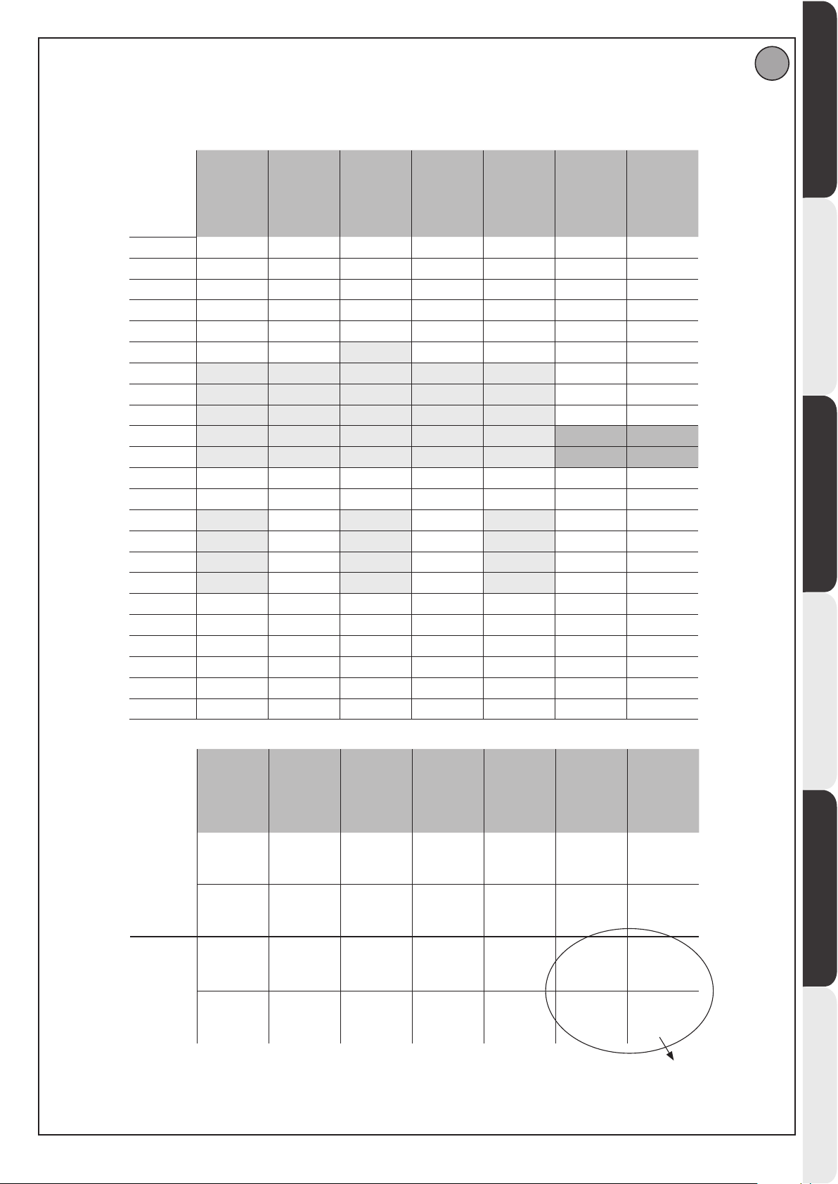
PROGRAMMAZIONE MENÙ CHRONO CHRONO MENU PROGRAMMING CHRONO MENU PROGRAMMING
PROGRAMMIERUNG MENÜ CHRONO PROGRAMACIÓN MENÚ CHRONO PROGRAMMERING CHRONOMENU
I
D812865 00100_04
Les valeurs sont programmables par étape de 10 minutes - Die Werte können in Schritten von 10 Minuten programmiert werden
Los valores se puede programar con intervalos de 10 minutos - De waarden zijn programmeerbaar met stappen van 10 minuten
I valori sono programmabili a step di 10 minuti - Values are programmable in 10 minutes’ steps
Sabato
Saturday
Samedi
Samstag
Sábado
Zaterdag
00:00
01:00
02:00
03:00
04:00
05:00
06:00
07:00
08:00
09:00
10:00
11:00
12:00
13:00
14:00
15:00
16:00
17:00
18:00
19:00
20:00
21:00
22:00
23:00
Lunedì
Monday
Lundi
Montag
Lunes
Maandag
Martedì
Tuesday
Mardi
Dienstag
Martes
Dinsdag
Mercoledì
Wednesday
Mercredi
Mittwoch
Miércoles
Woensdag
Giovedì
Thursday
Jeudi
Donnerstag
Jueves
Donderdag
Venerdì
Friday
Vendredi
Freitag
Viernes
Vrijdag
Domenica
Sunday
Dimanche
Sonntag
Domingo
Zondag
ENGLISH FRANÇAIS ESPAÑOL
DEUTSCHITALIANO
Fascia 1
Time band 1
Tranche1
Zeitraum 1
Franja 1
Bereik 1
Fascia 2
Time band 2
Tranche 2
Zeitraum 2
Franja 2
Bereik 2
Lunedì
Monday
Lundi
Montag
Lunes
Maandag
Inizio / Beginning
Début / Beginn
Inicio / Begin
07.00
Fine / End
Fin / Ende
Final / Einde
12.00
Inizio / Beginning
Début / Beginn
Inicio / Begin
14.00
Fine / End
Fin / Ende
Final / Einde
18.00
Martedì
Tuesday
Mardi
Dienstag
Martes
Dinsdag
Inizio / Beginning
Début / Beginn
Inicio / Begin
07.00
Fine / End
Fin / Ende
Final / Einde
12.00
Inizio / Beginning
Début / Beginn
Inicio / Begin
00.00
Fine / End
Fin / Ende
Final / Einde
00.00
Mercoledì
Wednesday
Mercredi
Mittwoch
Miércoles
Woensdag
Inizio / Beginning
Début / Beginn
Inicio / Begin
06.00
Fine / End
Fin / Ende
Final / Einde
12.00
Inizio / Beginning
Début / Beginn
Inicio / Begin
14.00
Fine / End
Fin / Ende
Final / Einde
18.00
Giovedì
Thursday
Jeudi
Donnerstag
Jueves
Donderdag
Inizio / Beginning
Début / Beginn
Inicio / Begin
07.00
Fine / End
Fin / Ende
Final / Einde
12.00
Inizio / Beginning
Début / Beginn
Inicio / Begin
00.00
Fine / End
Fin / Ende
Final / Einde
00.00
Venerdì
Friday
Vendredi
Freitag
Viernes
Vrijdag
Inizio / Beginning
Début / Beginn
Inicio / Begin
07.00
Fine / End
Fin / Ende
Final / Einde
12.00
Inizio / Beginning
Début / Beginn
Inicio / Begin
14.00
Fine / End
Fin / Ende
Final / Einde
18.00
Fascia non programmata. Viene lasciata a 0
No scheduled time zone. It is left at 0
Tranche non programmée. Est laissée à 0
Zeitraum nicht programmiert. Wird auf 0 gelassen
Franja no programada. Se deja en 0
Niet geprogrammeerd bereik Wordt losgelaten op 0
Sabato
Saturday
Samedi
Samstag
Sábado
Zaterdag
Inizio / Beginning
Début / Beginn
Inicio / Begin
10.00
Fine / End
Fin / Ende
Final / Einde
12.00
Inizio / Beginning
Début / Beginn
Inicio / Begin
00.00
Fine / End
Fin / Ende
Final / Einde
00.00
Domenica
Sunday
Dimanche
Sonntag
Domingo
Zondag
Inizio / Beginning
Début / Beginn
Inicio / Begin
10.00
Fine / End
Fin / Ende
Final / Einde
12.00
Inizio / Beginning
Début / Beginn
Inicio / Begin
00.00
Fine / End
Fin / Ende
Final / Einde
00.00
NEDERLANDS
RIGEL 6 - 25
Page 26
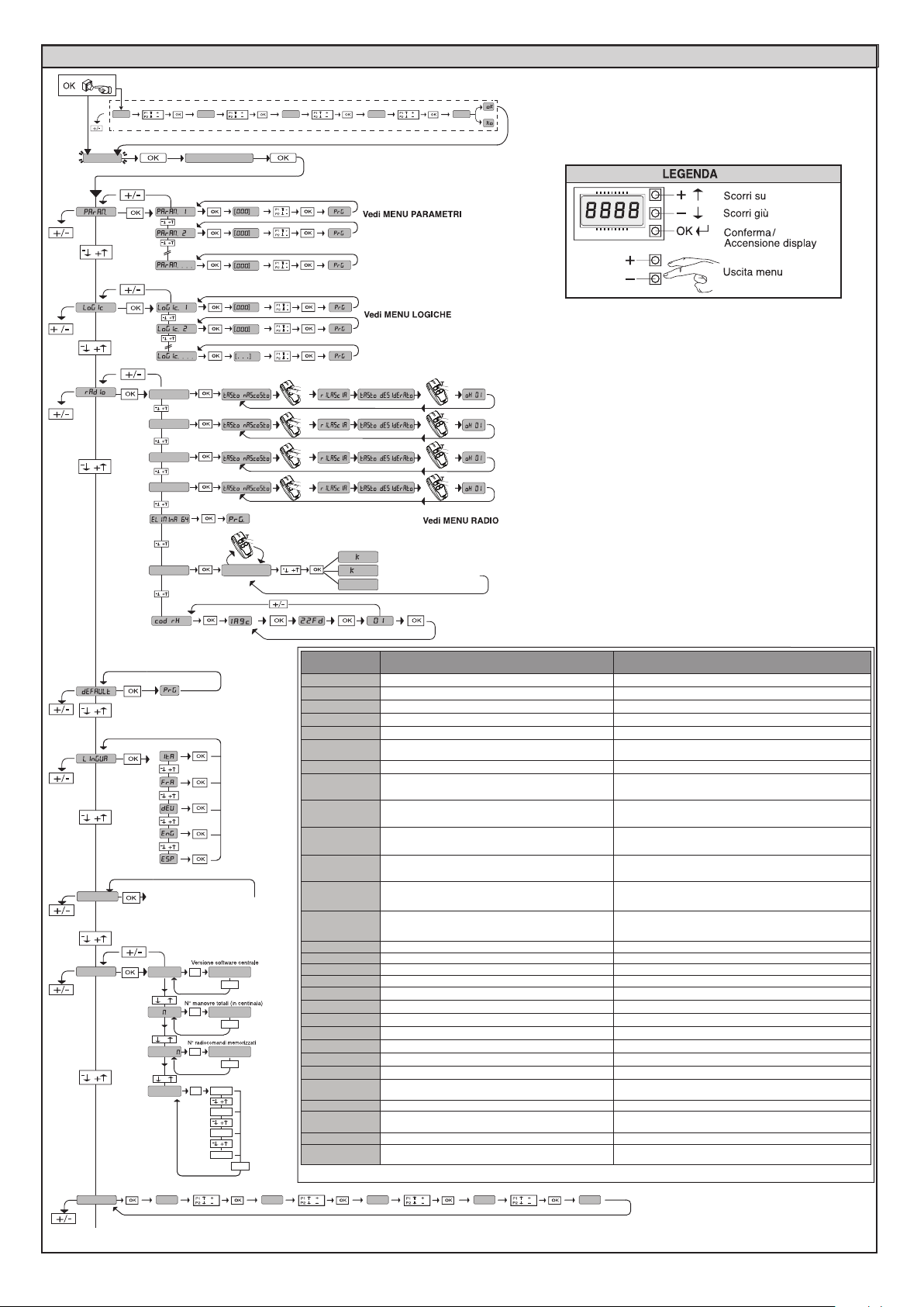
x2
MANUALE PER L’INSTALLAZIONE
ACCESSO AI MENU Fig. 1
***
0---
ALT SEGUIRE IL MANUALE
elimina 1 ( 0001 )
10--
agg. 1ch
agg. 2ch
agg. 3ch
agg. 4ch
150- 1520 ok
o
se cancellato
o
se non presente
se clone, viene disabilitato
dis
*** Inserimento password.
Richiesta con logica Livello Protezione
impostata a 1, 2, 3, 4
D812865 00100_04
autoset
stat
password
Per menù AUTOSET
vedi menù semplificato
OK
vers
+
n. an
+
n. teleco
+
err
0---
bft . . .
+/-
OK
0000
+/-
OK
00
+/-
Elenco ultimi 30 errori
OK
01.33
02.01
........
30.15
+/-
Codice
diagnoistica
STRE
STRI
OPEN
CLS
PED
TIME
STOP
PHOT
PHOP
PHCL
BAR
baro
barc
SWC1
SWO1
SWC2
SWO2
ER01
ER02
ER03
ER04
ER06
ER07
ER08
ER1x
ER3x
ER7x
ERf3
ERF9
10--
Attivazione ingresso start esterno START E
Attivazione ingresso start interno START I
Attivazione ingresso OPEN
Attivazione ingresso CLOSE
Attivazione ingresso pedonale PED
Attivazione ingresso TIMER o attivazione fascia oraria
programmata
Attivazione ingresso STOP
Attivazione ingresso fotocellula PHOT o se congurato come
fotocellula vericata, Attivazione dell’ingresso FAULT associato
Attivazione ingresso fotocellula in apertura PHOT OP o se
congurato come fotocellula vericata attiva solo in apertura,
Attivazione dell’ingresso FAULT associato
Attivazione ingresso fotocellula in chiusura PHOT CL o se
congurato come fotocellula vericata attiva solo in chiusura,
Attivazione dell’ingresso FAULT associato
Attivazione ingresso costa BAR o se congurato come costa
sensibile vericata, Attivazione dell’ingresso FAULT associato
Attivazione ingresso costa BAR con inversione ATTIVA SOLO IN
APERTURA o se congurato come costa sensibile vericata attiva solo in apertura, Attivazione dell’ingresso FAULT associato
Attivazione ingresso costa BAR con inversione ATTIVA SOLO IN
CHIUSURA o se congurato come costa sensibile vericata attiva solo in chisuura, Attivazione dell’ingresso FAULT associato
Attivazione ingresso necorsa chiusura del motore 1 SWC1
Attivazione ingresso necorsa apertura del motore 1 SWO1
Attivazione ingresso necorsa chiusura del motore 2 SWC2
Attivazione ingresso necorsa apertura del motore 2 SWO2
Test fotocellule fallito Vericare collegamento fotocellule e/o impostazioni logiche
Test costa fallito Vericare collegamento coste e/o impostazioni logiche
Test fotocellule apertura fallito Vericare collegamento fotocellule e/o impostazione parametri/logiche
Test fotocellule chiusura fallito Vericare collegamento fotocellule e/o impostazione parametri/logiche
Test costa 8k2 fallito Vericare collegamento coste e/o impostazioni parametri/logiche
Test costa apertura fallito Vericare collegamento coste e/o impostazioni parametri/logiche
Test costa chiusura fallito Vericare collegamento coste e/o impostazioni parametri/logiche
*
Errore test hardware scheda
*
Inversione per ostacolo - Amperostop Vericare eventuali ostacoli lungo il percorso
*
Errore interno di controllo supervisione sistema.
Errore nell’impostazione degli ingressi SAFE Vericare la corretta impostazione degli ingressi SAFE
Sovraccarico uscita elettroserratura
*X= 0, 1, .., 9, A, B, C, D, E, F
150- 1520 prg
Descrizione Note
- Vericare collegamenti al motore
- Problemi hardware alla scheda (contattare l’assistenza tecnica)
Provare a spegnere e riaccendere la scheda. Se il problema persiste
contattare l’assistenza tecnica.
- Vericare collegamenti serratura
- Serratura non adeguata
26 - RIGEL 6
Page 27
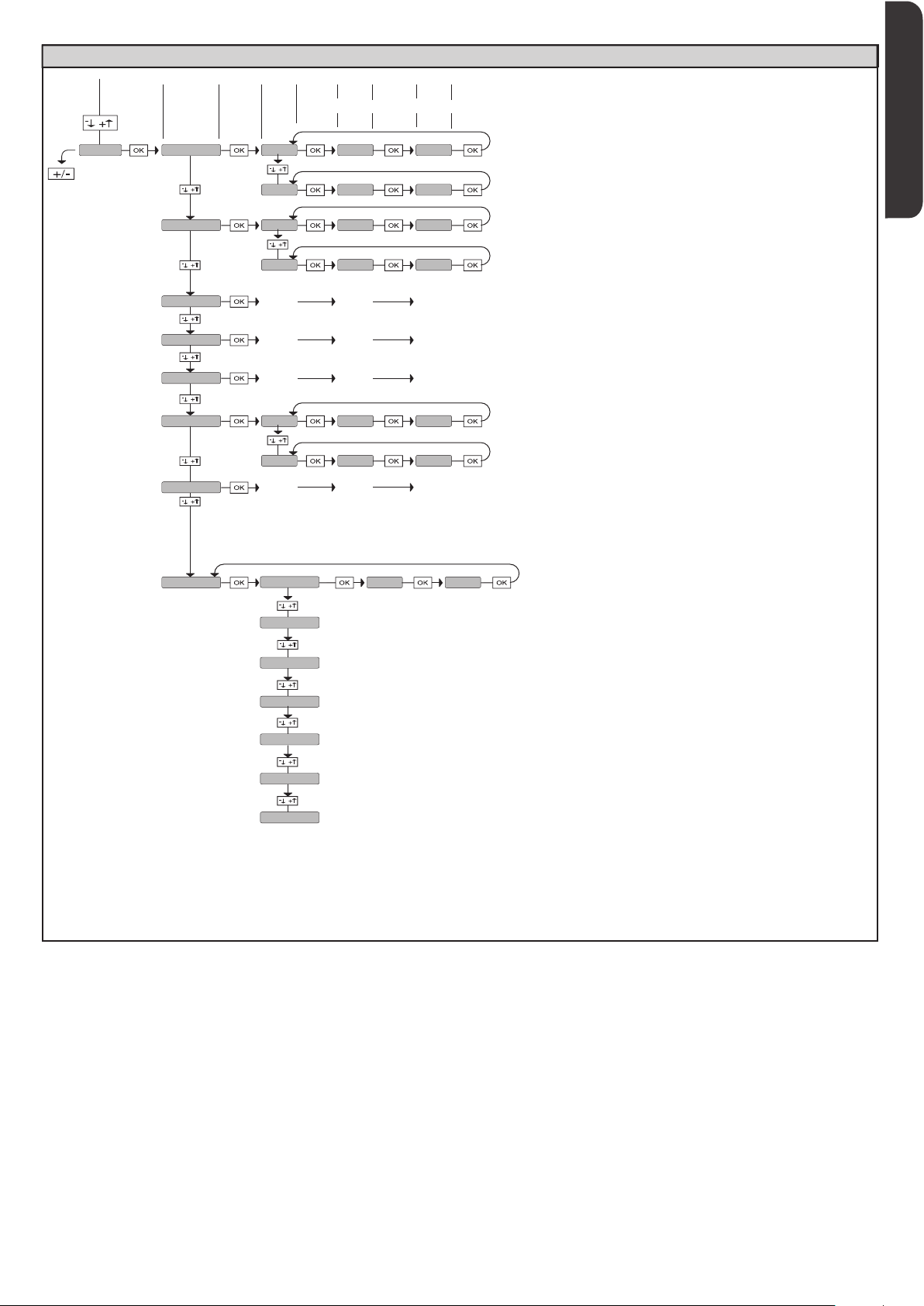
MANUALE PER L’INSTALLAZIONE
ACCESSO AI MENU Fig. 1
ITALIANO
D812865 00100_04
GIORNO
domenica 01 10-0 12-0chrono
lunedì
martedì
mercoledì
giovedì
venerdì
sabato
FASCIA
02 00-0 00-0
01 07-0 12-0
02 14-0 18-0
.... .... ....
.... .... ....
.... .... ....
01 07-0 12-0
02 14-0 18-0
.... .... ....
INIZIO FINE
[00:00 - 24:00] [00:00 - 24:00]
domenica
lunedì
martedì
mercoledì
giovedì
venerdì
sabato
00 00hh-MM
[00-23]
Regola ora
[00:59]
Regola minuti
Regolazione orologio
RIGEL 6 - 27
Page 28
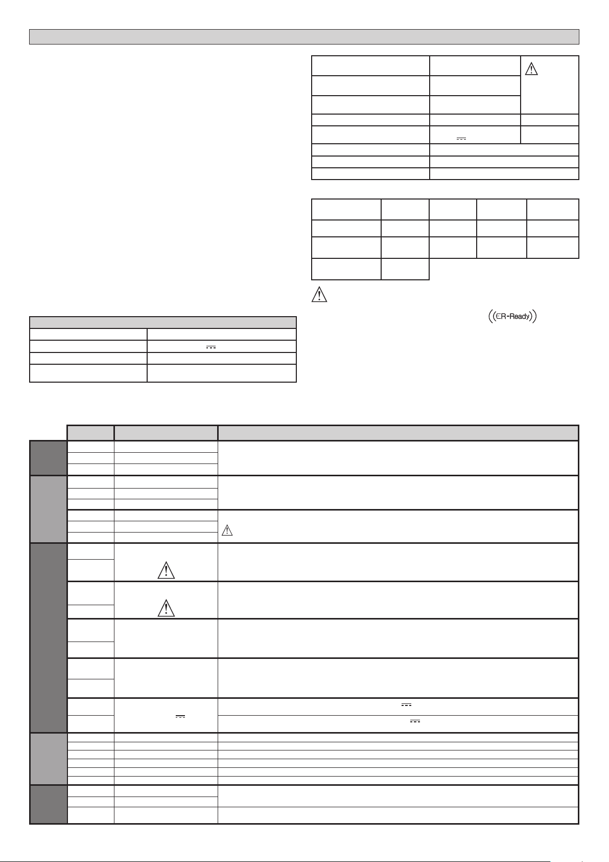
MANUALE PER L’INSTALLAZIONE
2) GENERALITÁ
Il quadro comandi RIGEL 6 viene fornito dal costruttore con settaggio standard.
Qualsiasi variazione, deve essere impostata mediante il programmatore a display
incorporato o mediante programmatore palmare universale. Supporta completamente il protocollo EELINK.
Le caratteristiche principali sono:
- Controllo di 1 o 2 motori monofase provvisti di pastiglia termica
Nota: Devono essere utilizzati 2 motori dello stesso tipo.
- Regolazione elettronica della coppia
- Ingressi controllo necorsa chiusura/apertura separati per ogni motore
- Ingressi separati per le sicurezze
- Gestione fasce orarie
- Rilevamento ostacolo integrato
- Preriscaldamento motori con lettura sonda integrato
- Frenatura elettrodinamica regolabile
- Rallentamento della velocità all’accostamento
- Ricevitore radio incorporato rolling-code con clonazione trasmettitori.
La scheda è dotata di una morsettiera di tipo estraibile per rendere più agevole
la manutenzione o la sostituzione. Viene fornita con una serie di ponti precablati
per facilitare l’installatore in opera.
I pon ti rigua rdano i morsett i: 41-42, 41-43, 41-44, 41-45, 70-71, 70-72, 7074, 76-77, 76-79, 81-82, 81-84. Se i morsetti sopraindicati vengono utilizzati,
togliere i rispettivi ponti.
VERIFICA
Il quadro
dispositivi di sicurezza (fotocellule e coste), prima di eseguire ogni ciclo di apertura
e chiusura.
In caso di malfunzionamenti vericare il regolare funzionamento dei dispositivi
collegati e controllare i cablaggi.
ATTENZIONE!: se l’anta è installata in area pubblica oppure se è abilitata una
modalità automatica di funzionamento, si raccomanda l’installazione di una
coppia di fotocellule ad altezza di 5 cm e di una coppia ad altezza 40-50 cm. Per
modalità automatica si intende qualsiasi comando non attivato in modo volontario
dall’utente (esempio: funzione TCA, chrono, ecc)
RIGEL 6
eettua il controllo (verica) dei relè di marcia, dei triac e dei
3) DATI TECNICI
Alimentazione 220-230V 50/60Hz(*)
Isolamento rete/bassa tensione > 2MOhm 500V
Rigidità dielettrica rete/bt 3750V~ per 1 minuto
Alimentazione accessori
24V~ (1A assorbimento max)
24V~safe
AUX 0
AUX 1
AUX 2
Contatto alimentato
220-230V~N.O. (80W MAX)
Contatto alimentato
220-230V~N.O. (80W MAX)
Contatto N.O.
(MAX 220-230V~ 80W)
AUX0+
AUX1+
AUX2=
80W MAX
AUX 3 Contatto N.O. (Max 24V~) 10W MAX
LOCK
Uscita per elettroserratura 12V
:
10W MAX
Fusibili vedi Fig. B
N° combinazioni 4 miliardi
N° max radiocomandi memorizzabili
63
(* altre tensioni disponibili a richiesta)
Ciclo di utilizzo continuo continuo 1 min. ON/
Temperatura
di funzionamento
Potenza massima
motori 220-230V
Potenza massima
motori 110-120V
-20°C/+50°C -20°C/+55°C -20°C/+50°C -20°C/+55°C
2x375 W
1x750 W
2x320 W
1x390 W
2x250 W
1x500 W
2 min. OFF
2x650 W
1x750 W
1 min. ON/
2 min. OFF
2x500 W
1x750 W
M1+M2+AUX0+AUX1+AUX2+AUX3+LOCK= 1300W MAX T=+50°C
Versioni trasmettitori utilizzabili:
Tutti i trasmettitori ROLLING CODE compatibili con
4) PREDISPOSIZIONE TUBI Fig. A
5) COLLEGAMENTI MORSETTIERA Fig. B
AVVERTENZE - Nelle operazioni di cablaggio ed installazione riferirsi alle norme
vigenti e comunque ai principi di buona tecnica.
I conduttori alimentati con tensioni diverse, devono essere sicamente separati,
oppure devono essere adeguatamente isolati con isolamento supplementare
di almeno 1mm.
I conduttori devono essere vincolati da un ssaggio supplementare in prossimità
dei morsetti, per esempio mediante fascette.
Tutti i cavi di collegamento devono essere mantenuti adeguatamente lontani
dal dissipatore.
D812865 00100_04
Morsetto Denizione Descrizione
L FASE
Alimenta-
Alim.
zione
Motore
Aux
Finecorsa
Accessori
N NEUTRO
GND TERRA
10 MOT1 MARCIA
11 MOT 1 COM
12 MOT1 MARCIA
14 MOT 2 MARCIA
15 MOT 2 COM
16 MOT 2 MARCIA
20
21
22
23
24
25
26
27
28
29
40 Non utilizzato
41 + REF SWE Comune necorsa
42 SWC 1 Finecorsa di chiusura del motore 1 SWC1 (N.C.).
43 SWO 1 Finecorsa di apertura del motore 1 SWO1 (N.C.).
44 SWC 2 Finecorsa di chiusura del motore 2 SWC2 (N.C.).
45 SWO 2 Finecorsa di apertura del motore 2 SWO2 (N.C.).
50 24V51 24V+
52 24 Vsafe+
AUX 0 - CONTATTO ALIMENTATO
AUX 1 - CONTATTO ALIMENTATO
AUX 2 - CONTATTO LIBERO (N.O.)
AUX 3 - CONTATTO LIBERO (N.O.)
220-230V~
220-230V~
LOCK 12
Alimentazione monofase
Collegamento motore 1. Sfasamento ritardato in chiusura.
Collegamento motore 2. Sfasamento ritardato in apertura.
Nota: se “1 mot.att”=1 non collegare nessun cavo sui morsetti 14-15-16
Uscita congurabile AUX 0 - Default LAMPEGGIANTE.
CANALE RADIO MONOSTABILE / SPIA CANCELLO APERTO SCA/ Comando LUCE CORTESIA/ Comando LUCE ZONA/ LUCE
SCALE/ ALLARME CANCELLO APERTO/ LAMPEGGIANTE/ ELETTROSERRATURA A SCATTO/ ELETTROSERRATURA A MAGNETE/ MANUTENZIONE/ LAMPEGGIANTE E MANUTENZIONE / STATO CANCELLO / CANALE RADIO BISTABILE / CANALE
RADIO TEMPORIZZATO. Far riferimento alla tabella “Congurazione delle uscite AUX”.
Uscita congurabile AUX 1 - Default Uscita LUCE ZONA.
CANALE RADIO MONOSTABILE / SPIA CANCELLO APERTO SCA/ Comando LUCE CORTESIA/ Comando LUCE ZONA/ LUCE
SCALE/ ALLARME CANCELLO APERTO/ LAMPEGGIANTE/ ELETTROSERRATURA A SCATTO/ ELETTROSERRATURA A MAGNETE/ MANUTENZIONE/ LAMPEGGIANTE E MANUTENZIONE / STATO CANCELLO / CANALE RADIO BISTABILE / CANALE
RADIO TEMPORIZZATO. Far riferimento alla tabella “Congurazione delle uscite AUX”.
Uscita congurabile AUX 2 - Default Uscita SPIA CANCELLO APERTO SCA.
CANALE RADIO MONOSTABILE / SPIA CANCELLO APERTO SCA/ Comando LUCE CORTESIA/ Comando LUCE ZONA/ LUCE
SCALE/ ALLARME CANCELLO APERTO/ LAMPEGGIANTE/ ELETTROSERRATURA A SCATTO/ ELETTROSERRATURA A MAGNETE/ MANUTENZIONE/ LAMPEGGIANTE E MANUTENZIONE / STATO CANCELLO / CANALE RADIO BISTABILE / CANALE
RADIO TEMPORIZZATO. Far riferimento alla tabella “Congurazione delle uscite AUX”.
Uscita congurabile AUX 3 - Default Uscita CANALE RADIO MONOSTABILE
CANALE RADIO MONOSTABILE / SPIA CANCELLO APERTO SCA/ Comando LUCE CORTESIA/ Comando LUCE ZONA/ LUCE
SCALE/ ALLARME CANCELLO APERTO/ LAMPEGGIANTE/ ELETTROSERRATURA A SCATTO/ ELETTROSERRATURA A MAGNETE/ MANUTENZIONE/ LAMPEGGIANTE E MANUTENZIONE / STATO CANCELLO / CANALE RADIO BISTABILE / CANALE
RADIO TEMPORIZZATO. Far riferimento alla tabella “Congurazione delle uscite AUX”.
Logica Tipo serratura= 0 - Uscita elettroserratura a scatto 12V
Uscita attivata con un impulso ad ogni apertura e chiusura
Logica Tipo serratura= 1 - Uscita elettroserratura a magnete 12V
Uscita Attivata con cancello chiuso ed in chiusura
Uscita alimentazione accessori.
Uscita alimentazione per dispositivi di sicurezza vericati (trasmettitore fotocellule e trasmettitore costa sensibile).
Uscita attiva solo durante il ciclo di manovra.
220-230V 50/60Hz(*)
(MODELLO ECB)
28 - RIGEL 6
Page 29

D812865 00100_04
Comandi
Sicurezze
Antenna
NTC
MANUALE PER L’INSTALLAZIONE
Morsetto Denizione Descrizione
60 Comune
61 IC 1
62 IC 2
63 Comune
64 IC 3
65 IC 4
70 Comune
71 STOP
72 SAFE 1
73 FAULT 1 Ingresso verica dispositivi di sicurezza collegati al SAFE 1.
74 SAFE 2
75 FAULT 2
76 Comune
77 SAFE 3
78 FAULT 3 Ingresso verica dispositivi di sicurezza collegati al SAFE 3.
79 SAFE 4
80 FAULT 4
81 Comune
82 SAFE 5
83 FAULT 5 Ingresso verica dispositivi di sicurezza collegati al SAFE 5.
84 SAFE 6
85 FAULT 6
Y ANTENNA
# SHIELD
NTC Ingesso per collegamento della sonda di temperatura
Comune ingressi IC 1 e IC 2
Ingresso di comando congurabile 1 (N.O.) - Default START E.
START E / START I / OPEN / CLOSE / PED / TIMER / TIMER PED
Far riferimento alla tabella “Congurazione degli ingressi di comando”.
Ingresso di comando congurabile 2 (N.O.) - Default PED.
START E / START I / OPEN / CLOSE / PED / TIMER / TIMER PED
Far riferimento alla tabella “Congurazione degli ingressi di comando”.
Comune ingressi IC 3 e IC 4
Ingresso di comando congurabile 3 (N.O.) - Default OPEN.
START E / START I / OPEN / CLOSE / PED / TIMER / TIMER PED
Far riferimento alla tabella “Congurazione degli ingressi di comando”.
Ingresso di comando congurabile 4 (N.O.) - Default CLOSE.
START E / START I / OPEN / CLOSE / PED / TIMER / TIMER PED
Far riferimento alla tabella “Congurazione degli ingressi di comando”.
Comune ingressi STOP, SAFE 1 e SAFE 2
Il comando interrompe la manovra. (N.C.)
Se non si utilizza lasciare il ponticello inserito.
Ingresso di sicurezza congurabile 1 (N.C.) - Default PHOT.
PHOT / PHOT TEST / PHOT OP / PHOT OP TEST / PHOT CL / PHOT CL TEST / BAR / BAR TEST / BAR 8K2/ B
TEST / BAR 8K2 OP/ BAR CL / BAR CL TEST / BAR 8K2 CL
Far riferimento alla tabella “Congurazione degli ingressi di sicurezza”.
Ingresso di sicurezza congurabile 2 (N.C.) - Default BAR.
PHOT / PHOT TEST / PHOT OP / PHOT OP TEST / PHOT CL / PHOT CL TEST / BAR / BAR TEST / BAR 8K2 / B
TEST / BAR 8K2 OP/ BAR CL / BAR CL TEST / BAR 8K2 CL
Far riferimento alla tabella “Congurazione degli ingressi di sicurezza”.
Ingresso verica dispositivi di sicurezza collegati al SAFE 2.
Comune ingresso SAFE 3, SAFE 4.
Ingresso di sicurezza congurabile 3 (N.C.) - Default PHOT OP.
PHOT / PHOT TEST / PHOT OP / PHOT OP TEST / PHOT CL / PHOT CL TEST / BAR / BAR TEST / BAR OP / BAR OP TEST / BAR
CL / BAR CL TEST /
Far riferimento alla tabella “Congurazione degli ingressi di sicurezza”.
Ingresso di sicurezza congurabile 4 (N.C.) - Default PHOT CL.
PHOT / PHOT TEST / PHOT OP / PHOT OP TEST / PHOT CL / PHOT CL TEST / BAR / BAR TEST / BAR OP / BAR OP TEST / BAR
CL / BAR CL TEST /
Far riferimento alla tabella “Congurazione degli ingressi di sicurezza”.
Ingresso verica dispositivi di sicurezza collegati al SAFE 4.
Comune ingresso SAFE 5, SAFE 6.
Ingresso di sicurezza congurabile 5 (N.C.) - Default PHOT.
PHOT / PHOT TEST / PHOT OP / PHOT OP TEST / PHOT CL / PHOT CL TEST / BAR / BAR TEST/ BAR OP / BAR OP TEST / BAR
CL / BAR CL TEST /
Far riferimento alla tabella “Congurazione degli ingressi di sicurezza”.
Ingresso di sicurezza congurabile 6 (N.C.) - Default BAR.
PHOT / PHOT TEST / PHOT OP / PHOT OP TEST / PHOT CL / PHOT CL TEST / BAR / BAR TEST
CL / BAR CL TEST /
Far riferimento alla tabella “Congurazione degli ingressi di sicurezza”.
Ingresso verica dispositivi di sicurezza collegati al SAFE 6.
Ingresso antenna.
Usare una antenna accordata sui 433MHz. Per il collegamento Antenna-Ricevente usare cavo coassiale RG58. La presenza di masse metalliche a ridosso dell’antenna, può disturbare la ricezione radio. In caso di scarsa portata del trasmettitore, spostare l’antenna in un punto più idoneo.
ITALIANO
AR OP / BAR OP
AR OP / BAR OP
/ BAR OP / BAR OP TEST / BAR
Congurazione delle uscite AUX
Logica Aux= 0 - Uscita CANALE RADIO MONOSTABILE.
Il contatto rimane chiuso per 1s all’attivazione del canale radio.
Logica Aux= 1 - Uscita SPIA CANCELLO APERTO SCA.
Il contatto rimane chiuso durante l’apertura e ad anta aperta, intermittente durante la chiusura, aperto ad anta chiusa.
Logica Aux= 2 - Uscita comando LUCE CORTESIA.
Il contatto rimane chiuso per 90 secondi dopo l’ultima manovra.
Logica Aux= 3 - Uscita comando LUCE ZONA.
Il contatto rimane chiuso per tutta la durata della manovra.
Logica Aux= 4 - Uscita LUCE SCALE.
Il contatto rimane chiuso per 1 secondo all’inizio della manovra.
Logica Aux= 5 - Uscita ALLARME CANCELLO APERTO.
Il contatto rimane chiuso se l’anta rimane aperta per un tempo doppio rispetto al TCA impostato.
Logica Aux= 6 - Uscita per LAMPEGGIANTE.
Il contatto rimane chiuso durante la movimentazione delle ante.
Logica Aux= 7 - Uscita per ELETTROSERRATURA A SCATTO.
Il contatto rimane chiuso per 2 secondi ad ogni apertura e ad ogni chiusura.
Logica Aux= 8 - Uscita per ELETTROSERRATURA A MAGNETE.
Il contatto rimane chiuso a cancello chiuso e durante la manovra di chiusura.
Logica Aux= 9 - Uscita MANUTENZIONE.
IL contatto rimane chiuso al raggiungimento del valore impostato nel parametro Manutenzione, per segnalare la richiesta di manutenzione.
Logica Aux= 10 - Uscita LAMPEGGIANTE E MANUTENZIONE.
Il contatto rimane chiuso durante la movimentazione delle ante. Se viene raggiunto il valore impostato nel parametro Manutenzione, a ne manovra, ad anta chiusa, il contatto per 4
volte si chiude per 10s e si apre per 5s per segnalare la richiesta di manutenzione.
Logica Aux= 11 - Non disponibile
Logica Aux= 12 - Non disponibile
Logica Aux= 13 - Uscita STATO CANCELLO.
Il contatto rimane chiuso quando il cancello è chiuso
RIGEL 6 - 29
Page 30

MANUALE PER L’INSTALLAZIONE
Congurazione delle uscite AUX
Logica AUX= 14 - Uscita CANALE RADIO BISTABILE
Il contatto cambia stato (aperto-chiuso) all’attivazione del canale radio
Logica AUX= 15 - Uscita CANALE RADIO TEMPORIZZATA
Il contatto rimane chiuso per un tempo programmabile all’attivazione del canale Radio (tempo uscita)
Se durante tale tempo il tasto viene nuovamente premuto, il conteggio del tempo riparte.
Congurazione degli ingressi di comando
Logica IC= 0 - Ingresso congurato come Start E. Funzionamento secondo la Logica mov.passo passo. Start esterno per la gestione semaforo.
Logica IC= 1 - Ingresso congurato come Start I. Funzionamento secondo la Logica mov.passo passo. Start interno per la gestione semaforo.
Logica IC= 2 - Ingresso congurato come Open.
Il comando esegue un’apertura. Se il l’ingresso rimane chiuso, le ante rimangono aperte no all’apertura del contatto. A contatto aperto l’automazione chiude dopo il tempo di tca, se
attivato.
Logica IC= 3 - Ingresso congurato come Close.
Il comando esegue una chiusura.
Logica IC= 4 - Ingresso congurato come Ped.
Il comando esegue un’apertura pedonale, parziale. Funzionamento secondo la Logica mov.passo passo.
Logica IC= 5 - Ingresso congurato come Timer.
Funzionamento analogo al open ma la chiusura è garantita anche dopo l’assenza di rete.
Logica IC= 6 - Ingresso congurato come Timer Ped.
Il comando esegue un’apertura pedonale, parziale. Se l’ingresso rimane chiuso, l’anta rimane aperta no all’apertura del contatto. Se il l’ingresso rimane chiuso e viene attivato un
comando di Start E, Start I o Open viene eseguita una manovra completa per poi ripristinarsi in apertura pedonale. La chiusura è garantita anche dopo l’assenza di rete.
Congurazione degli ingressi di sicurezza
Logica SAFE= 0 - Ingresso congurato come Phot, fotocellula non vericata (*) (Fig.F, rif.1).
Consente la connessione di dispositivi non dotati di contatto supplementare di verica. In caso di oscuramento, le fotocellule sono attive sia in apertura che in chiusura. Un oscuramento della fotocellula in chiusura, inverte il moto solo dopo il disimpegno della fotocellula. Se non si utilizza lasciare il ponticello inserito.
Logica SAFE= 1 - Ingresso congurato come Phot test, fotocellula vericata. (Fig.F, rif.2).
Attiva la verica delle fotocellule ad inizio manovra. In caso di oscuramento, le fotocellule sono attive sia in apertura che in chiusura. Un oscuramento della fotocellula in chiusura,
inverte il moto solo dopo il disimpegno della fotocellula.
Logica SAFE= 2 - Ingresso congurato come Phot op, fotocellula attiva solo in apertura non vericata (*) (Fig.F, rif.1).
Consente la connessione di dispositivi non dotati di contatto supplementare di verica. In caso di oscuramento è escluso il funzionamento della fotocellula in chiusura. In fase di
apertura blocca il moto per la durata dell’oscuramento della fotocellula. Se non si utilizza lasciare il ponticello inserito.
Logica SAFE= 3 - Ingresso congurato come Phot op test, fotocellula vericata attiva solo in apertura (Fig.F, rif.2).
Attiva la verica delle fotocellule ad inizio manovra. In caso di oscuramento è escluso il funzionamento della fotocellula in chiusura. In fase di apertura blocca il moto per la durata
dell’oscuramento della fotocellula.
Logica SAFE= 4 - Ingresso congurato come Phot cl, fotocellula attiva solo in chiusura non vericata (*) (Fig.F, rif.1).
Consente la connessione di dispositivi non dotati di contatto supplementare di verica. In caso di oscuramento è escluso il funzionamento della fotocellula in apertura. In fase di
chiusura, inverte immediatamente. Se non si utilizza lasciare il ponticello inserito.
Logica SAFE= 5 - Ingresso congurato come Phot cl test, fotocellula vericata attiva solo in chiusura (Fig.F, rif.2).
Attiva la verica delle fotocellule ad inizio manovra. In caso di oscuramento è escluso il funzionamento della fotocellula in apertura. In fase di chiusura, inverte immediatamente.
Logica SAFE= 6 - Ingresso congurato come Bar, costa sensibile non vericata (*) (Fig.F, rif.3).
Consente la connessione di dispositivi non dotati di contatto supplementare di verica. Il comando inverte il movimento per 2 sec. Se non si utilizza lasciare il ponticello inserito
Logica SAFE= 7 - Ingresso congurato come Bar, costa sensibile vericata (Fig.F, rif.4).
Attiva la verica delle coste sensibili ad inizio manovra. Il comando inverte il movimento per 2 sec.
Logica SAFE= 8 - Ingresso congurato come Bar 8k2 (Fig.F, rif.5). Ingresso per bordo resistivo 8K2.
Il comando inverte il movimento per 2 sec.
Logica SAFE=9 Ingresso congurato come Bar op, costa sensibile con inversione attiva solo in apertura, se attivata durante la chiusura eettua l’arresto dell’automazione (STOP) (Fig.F, rif. 3).
Consente la connessione di dispositivi non dotati di contatto supplementare di verica. L’intervento in fase di apertura provoca l’inversione del movimento per 2 sec, l’intervento in fase
di chiusura provoca l’arresto. Se non si utilizza lasciare il ponticello inserito.
Logica SAFE=10 Ingresso congurato come Bar op test, costa sensibile vericata con inversione attiva solo in apertura, se attivata durante la chiusura eettua l’arresto dell’automazione
(STOP) (Fig.F, rif. 4).
Attiva la verica delle coste sensibili ad inizio manovra. L’intervento in fase di apertura provoca l’inversione del movimento per 2 sec, l’intervento in fase di chiusura provoca l’arresto.
Logica SAFE=11 Ingresso congurato come Bar 8k2 op, costa 8k2 con inversione attiva solo in apertura, se attivata durante la chiusura eettua l’arresto dell’automazione (STOP) (Fig.F, rif. 5).
L’intervento in fase di apertura provoca l’inversione del movimento per 2 sec, l’intervento in fase di chiusura provoca l’arresto.
Logica SAFE=12 Ingresso congurato come Bar cl costa sensibile con inversione attiva solo in chiusura, se attivata durante l’apertura eettua l’arresto dell’automazione (STOP) (Fig.F, rif. 3).
Consente la connessione di dispositivi non dotati di contatto supplementare di verica. L’intervento in fase di chiusura provoca l’inversione del movimento per 2 sec, l’intervento in fase
di apertura provoca l’arresto. Se non si utilizza lasciare il ponticello inserito
Logica SAFE=13 Ingresso congurato come Bar cl test, costa sensibile vericata con inversione attiva solo in chiusura, se attivata durante l’apertura eettua l’arresto dell’automazione
(STOP) (Fig.F, rif. 4).
Attiva la verica delle coste sensibili ad inizio manovra. L’intervento in fase di chiusura provoca l’inversione del movimento per 2 sec, l’intervento in fase di apertura provoca l’arresto.
Logica SAFE=14 Ingresso congurato come Bar 8k2 cl, costa 8k2 con inversione attiva solo in chiusura, se attivata durante l’apertura eettua l’arresto dell’automazione (STOP) (Fig.F, rif. 5).
L’intervento in fase di chiusura provoca l’inversione del movimento per 2 sec, l’intervento in fase di apertura provoca l’arresto.
D812865 00100_04
(*) Se si si installano dispositivi di tipo “D” (come deniti dalla EN12453), collegati in modalità non vericata, prescrivere una manutenzione obbligatoria
con frequenza almeno semestrale.
30 - RIGEL 6
Page 31
MANUALE PER L’INSTALLAZIONE
ITALIANO
6) DISPOSITIVI DI SICUREZZA
Nota: utilizzare solamente dispositivi di sicurezza riceventi con contatto
in libero scambio.
D812865 00100_04
6.1) DISPOSITIVI VERIFICATI Fig. E
6.2) COLLEGAMENTO DI 1 COPPIA DI FOTOCELLULE NON VERIFICATE Fig. C
7 ACCESSO AI MENU: FIG. 1
7.1) MENU PARAMETRI PARA TABELLA “A” PARAMETRI
7.2) MENU LOGICHE LOGIC TABELLA “B” LOGICHE
7.3) MENU RADIO radio TABELLA “C” RADIO
- NOTA IMPORTANTE: CONTRASSEGNARE IL PRIMO TRASMETTITORE
MEMORIZZATO CON IL BOLLINO CHIAVE (MASTER).
Il primo trasmettitore, nel caso di programmazione manuale, assegna il CODICE
CHIAVE DELLA RICEVENTE; questo codice risulta necessario per poter eettuare
la successiva clonazione dei radiotrasmettitori.
La ricevente di bordo incorporato Clonix dispone inoltre di alcune importanti
funzionalità avanzate:
• Clonazionedeltrasmettitoremaster(rolling-codeocodicesso).
• Clonazionepersostituzioneditrasmettitorigiàinseritinellaricevente.
• Gestionedatabasetrasmettitori.
• Gestionecomunitàdiricevitori.
Per l’utilizzo di queste funzionalità avanzate fate riferimento alle istruzioni del pro grammatore palmare universale ed alla Guida generale programmazioni riceventi.
Nel caso di utilizzo di un radiocomando a 4 canali si raccomanda di riservarne
uno alla funzione di arresto (STOP).
7.4 MENU DEFAULT default
Riporta la centrale ai valori preimpostati dei DEFAULT. Dopo il ripristino è necessario eettuare un nuovo AUTOSET.
7.5 MENU LINGUA lingua
Consente di impostare la lingua del programmatore a display.
7.6 MENU AUTOSET AUTOset
Fasi di autoset per motori con necorsa (Fig. D1):
1 - Portare le ante in corrispondenza dei necorsa di chiusura.
2 - dare avvio ad una operazione di autosettaggio portandosi nell’apposito
Menu, premere il tasto OK, per far partire la manovra di apertura del motore
1.
3 - Nel display viene visualizzato il messaggio “M1.o”.
4 - Attendere l’intervento del necorsa di apertura per far terminare la manovra
di apertura del motore 1.
5 - Automaticamente parte la manovra di apertura del motore 2. A display “M2.o”.
6 - Attendere l’intervento del necorsa di apertura per far terminare la manovra
di apertura del motore 2, nel display viene visualizzato il messaggio “CLOSE”.
7 - Premere il tasto OK per far partire la manovra di chiusura del motore 2. A
display “M2.c”.
8 - Attendere l’intervento del necorsa di chiusura per far terminare la manovra
di chiusura del motore 2.
9 - Automaticamente parte la manovra di chiusura del motore 1. A display “M1.c”.
10 - Attendere l’intervento del necorsa di chiusura per far terminare la manovra
di chiusura del motore 1.
Se il tempo di lavoro è stato memorizzato correttamente nel display viene
visualizzato il messaggio “OPEN”.
11 - Premere il tasto OK per far partire il secondo ciclo per calcolare il valore di
coppia necessaria al movimento dell’anta/e, nel display viene visualizzato
il messaggio “M1.o”.
12 - Attendere l’intervento del necorsa di apertura per far terminare la manovra
di apertura del motore 1.
13 - Automaticamente parte la manovra di apertura del motore 2. A display “M2.o”.
14 - Attendere l’intervento del necorsa di apertura per far terminare la manovra
di apertura del motore 2, nel display viene visualizzato il messaggio “CLOSE”.
15 - Premere il tasto OK per far partire la manovra di chiusura del motore 2. A
display “M2.c”.
16 - Attendere l’intervento del necorsa di chiusura per far terminare la manovra
di chiusura del motore 2.
17 - Automaticamente parte la manovra di chiusura del motore 1. A display “M1.c”.
18 - Attendere l’intervento del necorsa di chiusura per far terminare la manovra
di chiusura del motore 1.
19 - Se l’autoset è stato concluso correttamente nel display viene visualizzato il
messaggio “OK”, se l’autoset fallisce nel display viene visualizzato il messaggio
“KO” e l’operazione va ripetuta dalla fase 1.
Se impostato 1 motore attivo, le fasi relative al motore 2 non vengono eseguite.
Fasi di autoset per motori sprovvisti di necorsa (Fig. D2):
1 - Portare le ante in corrispondenza dei fermi di chiusura.
2 - dare avvio ad una operazione di autosettaggio portandosi nell’apposito menu
premere il tasto OK, per far partire la manovra di apertura del motore 1,
3- Nel display viene visualizzato il messaggio “M1.o”.
4 - Premere il tasto Ok per terminare la manovra di apertura del motore 1. A
display “M2.o”
5 - Automaticamente parte la manovra di apertura del motore 2.
6 - Premere il tasto OK per terminare la manovra di apertura del motore 2, nel
display viene visualizzato il messaggio “CLOSE”.
7 - Premere il tasto OK per far partire la manovra di chiusura del motore 2. A
display “M2.c”
8 - Premere il tasto OK per terminare la manovra di chiusura del motore 2. A
display “M1.c”
9 - Automaticamente parte la manovra di chiusura del motore 1.
10 - Premere il tasto OK per terminare la manovra di chiusura del motore 1.
Se il tempo di lavoro è stato memorizzato correttamente nel display viene
visualizzato il messaggio “OPEN”.
11 - Premere il tasto OK per far partire il secondo ciclo per calcolare il valore di
coppia necessaria al movimento dell’anta/e, nel display viene visualizzato
il messaggio “M1.o”,
12 - Attendere l’intervento del tempo di lavoro del motore 1 per far terminare la
manovra di apertura del motore 1.
13 - Automaticamente parte la manovra di apertura del motore 2. A display “M2.o”
14 - Attendere l’intervento del tempo di lavoro del motore 2 per far terminare
la manovra di apertura del motore 2, nel display viene visualizzato il mes-
saggio “CLOSE”.
15 - Premere il tasto OK per far partire la manovra di chiusura del motore 2. A
display “M2.c”
16 - Attendere l’intervento del tempo di lavoro del motore 2 per far terminare la
manovra di chiusura del motore 2.
17 - Automaticamente parte la manovra di chiusura del motore 1. A display “M1.c”
18 - Attendere l’intervento del tempo di lavoro del motore 1 per far terminare
la manovra di chiusura del motore 1.
19 - Se l’autoset è stato concluso correttamente nel display viene visualizzato il
messaggio “OK”, se l’autoset fallisce nel display viene visualizzato il messaggio
“KO” e l’operazione va ripetuta dalla fase 1.
Se impostato 1 motore attivo, le fasi relative al motore 2 non vengono eseguite.
Durante questa fase è importante evitare l’oscuramento delle fotocellule, l’intervento delle sicurezze, nonchè l’utilizzo dei comandi START, STOP, OPEN, CLOSE
e del display.
Al termine di questa operazione la centrale di comando avrà automaticamente
impostato i valori ottimali dei parametri, tempi di lavoro. Vericarli ed eventualmente modicarli come descritto in programmazione.
ATTENZIONE!! Verificare che il valore della forza d’impatto
misurato nei punti previsti dalla norma EN12445, sia inferiore a quanto
indicato nella norma EN 12453.
Le forze di impatto devono essere limitate con l’utilizzo di coste attive
conformi alla norma EN12978.
Attenzione!! Durante l’autosettaggio la funzione di rilevamento
ostacoli non è attiva, l’installatore deve controllare il movimento
dell’automazione ed impedire a persone o cose di avvicinarsi o sostare
nel raggio di azione dell’automazione.
7.7)SEQUENZA VERIFICA INSTALLAZIONE
1. Applicare dispositivi di protezione sensibili alla pressione o elettrosensibili (per
esempio costa attiva)
2. Eseguire la manovra di AUTOSET (*)
3. Vericare le forze di impatto: se rispettano i limiti vai al punto 5 della sequenza
altrimenti
4. Consentire la movimentazione dell’azionamento solo in modalità “Uomo
presente”
5. Assicurarsi che tutti i dispositivi di rilevamento presenza nell’area di manovra
funzionino correttamente
(*) Prima di eseguire l’autoset assicurarsi di avere eettuato correttamente tutte le
operazioni di montaggio e di messa in sicurezza come prescritto dalle avvertenze
per l’installazione del manuale della motorizzazione e di aver impostato i parametri
forza apertura/chiusura, rallentamento e tempo rallentamento
7.8 MENU STATISTICHE
Consente di visualizzare la versione della scheda, il numero di manovre totali
(in centinaia), il numero di radiocomandi memorizzati e gli ultimi 30 errori (le
prime 2 cifre indicano la posizione, le ultime 2 il codice errore). L’errore 01 è
quello più recente.
7.9) MENU PASSWORD
Consente di impostare una password per la programmazione della scheda via
rete U-link.
Con la logica “LIVELLO PROTEZIONE” impostata a 1,2,3,4 viene richieta per accedere ai menu di programmazione. Dopo 10 tentativi consecutivi di accesso
falliti si dovranno attendere 3 minuti per un nuovo tentativo. Durante questo
periodo ad ogni tentativo di accesso il display visualizza “BLOC”. La password
di default è 1234.
7.10) MENU CHRONO Fig.I
Permette di impostare il funzionamento per fasce orarie.
Si possono programmare no a due fasce orarie giornaliere in cui il cancello
rimane aperto (da lunedì a domenica)
All’interno della fascia oraria viene eseguita un’apertura delle ante che rimangono aperte no al termine della fascia oraria.
8) PRESSIONE FINECORSA CHIUSURA Fig.F Rif. A-B
DIREZIONE APERTURA Fig.F Rif. C-D
9) COLLEGAMENTO CON SCHEDE DI ESPANSIONE E PROGRAMMATORE
PALMARE UNIVERSALE (Fig.G) Fare riferimento al manuale specico.
10) MODULI OPZIONALI U-LINK
Fare riferimento alle istruzioni dei moduli U-link
L’utilizzo di alcuni moduli comporta una riduzione della portata radio. Adeguare
l’impianto con opportuna antenna accordata sui 433MHz
11) RIPRISTINO DELLE IMPOSTAZIONI DI FABBRICA (Fig.H)
ATTENZIONE riporta la centrale ai valori preimpostati da fabbrica e vengono
cancellati tutti i radiocomandi in memoria.
ATTENZIONE! Un’errata impostazione può creare danni a persone, animali
o cose.
- Togliere tensione alla scheda (Fig.H rif.1)
- Aprire l’ingresso Stop e premere contemporaneamente i tasti - e OK (Fig.H rif.2)
- Dare tensione alla scheda (Fig.H rif.3)
- Il display visualizza RST, entro 3s dare conferma premendo il tasto OK (Fig.H rif.4)
- Attendere che la prodedura venga terminata (Fig.H rif.5)
- Procedura terminata (Fig.H rif.6)
ATTENZIONE! Un’errata impostazione può creare danni a persone, animali o cose.
ATTENZIONE: Verificare che il valore della forza d’impatto
misurato nei punti previsti dalla norma EN12445, sia inferiore a quanto
indicato nella norma EN 12453.
Le forze di impatto possono essere ridotte mediante l’utilizzo di bordi
deformabili.
Per ottenere un risultato migliore, si consiglia di eseguire l’autoset con motori a
riposo (cioè non surriscaldati da un numero considerevole di manovre consecutive).
RIGEL 6 - 31
Page 32

TABELLA “A” - MENU PARAMETRI - (param)
MANUALE PER L’INSTALLAZIONE
Parametro Min. Max.
t.lavoro
ot1
t.lavoro
ot2
t. APERT.
PARZIALE
T.SFAS.AP
T.SFAS.CH
t. rall
ot1
t. rall
ot2
TCA
T.SGOMB.
SEM.
t.uscita
FORZA AP
FORZA CH
Forza
rall.
freno
3.0 180.0 60.0
3.0 180.0 60.0
3 90 6 Apertura parziale M1 [s] Tempo di apertura parziale a seguito attivazione comando pedonale PED del motore M1
0 10 3
0 25 3
0 30 0
0 30 0
0 120 10
1 180 40
1 240 10
1 99 50
1 99 50
1 99 50
0 99 0
Default Personali
Denizione Descrizione
Tempo di lavoro
motore 1 [s]
Tempo di lavoro
motore 2 [s]
Tempo ritardo apertura
motore 2 [s]
Tempo di ritardo chiusura
motore 1 [s]
Tempo di rallentamento
motore 1 [s]
Tempo di rallentamento
motore 2 [s]
Tempo chiusura automa-
tica [s]
Tempo sgombero zona
semaforica [s]
Tempo di attivazione
dell’uscita temporizzata
[s]
Forza anta/e in apertura
[%]
Forza anta/e in chiusura
[%]
Forza motori
in rallentamento
[%]
Frenatura
[%]
Imposta il valore del tempo di lavoro in secondi per il motore 1 / 2
Alla ne di un autoset viene impostato con il valore reale di lavoro del motore
Tempo di ritardo all’apertura del motore 2 rispetto al motore 1.
Tempo di ritardo alla chiusura del motore 1 rispetto al motore 2.
Imposta il tempo di rallentamento all’accostamento. Il tempo di rallentamento viene sottratto
al tempo di lavoro.
NOTA: Usare questa funzione solo in presenza di necorsa.
NOTA: Non usare con motori idraulici.
(***)
Tempo di attesa prima della chiusura automatica.
Tempo di sgombero della zona interessata dal traco regolato dal semaforo.
Durata attivazione uscita canale radio temporizzata in secondi
Forza esercitata dall’anta/e in apertura.
Rappresenta la percentuale di forza erogata a regime rispetto al valore massimo.
ATTENZIONE: Inuisce direttamente nella forza di impatto: vericare che con il
valore impostato vengano rispettate le norme di sicurezza vigenti (*).
Installare dispositivi di sicurezza antischiacciamento (**).
(***)
Forza esercitata dall’anta/e in chiusura.
Rappresenta la percentuale di forza erogata a regime rispetto al valore massimo.
ATTENZIONE: Inuisce direttamente nella forza di impatto: vericare che con il
valore impostato vengano rispettate le norme di sicurezza vigenti (*).
Installare dispositivi di sicurezza antischiacciamento (**).
(***)
Forza esercitata dall’anta/e in rallentamento.
Rappresenta la percentuale di forza erogata in rallentamento.
ATTENZIONE: Inuisce direttamente nella forza di impatto: vericare che con il
valore impostato vengano rispettate le norme di sicurezza vigenti (*).
Installare dispositivi di sicurezza antischiacciamento (**).
(***)
Imposta il valore di frenatura da 0% (min.) a 99% (max.) compatibilmente con il peso del
cancello e con le sollecitazioni meccaniche presenti.
D812865 00100_04
freno
e er.
prerisc.
Sens. ost
manuten-
zione
0 99 60
0 99 30
0 99 0 Sensibilità ostacolo
0 250 0
Frenatura di emergenza
[%]
Preriscaldamento
[%]
Programmazione numero
manovre soglia
manutenzione
[in centinaia]
Imposta il valore da 0% (min.) a 99% (max.) della frenatura di emergenza, che viene eseguita
attivando i comandi di sicurezza presenti agli ingressi congurati come costa sensibilie BAR.
Imposta il valore percentuale di corrente da 0 (preriscaldamento disattivato) a 99% che si può
far passare negli avvolgimenti dei motori per mantenerli in temperatura.
NOTA: deve essere collegata la sonda di temperatura NTC.
La sonda deve essere posta e ssata a contatto con il motore per rilevare la temperatura esterna.
Permette di attivare la rilevazione dell’ostacolo.
La funzione è disattivata quando il parametro è impostato a 0. impostando il valore da 1 al
valore massimo è possibile aumentare la sensibilità all’ostacolo (valore max= sensibilità max)
Funziona solo con i necorsa.
ATTENZIONE: Questa funzione di rilevamento ostacolo non garantisce il rispetto
delle norme di sicurezza vigenti (*). Per rispettare le norme di sicurezza vigenti installare adeguati dispositivi di sicurezza antischiacciamento (**)
ATTENZIONE: il sistema rileva l’ostacolo solo se l’anta viene fermata; non vengono
rilevati ostacoli che frenano l’anta senza riuscire a fermarla.
Il rilevamento viene aettuato solo se l’anta che incontra l’ostacolo si sta muovendo a
velocità normale. Durante il rallentamento l’ostacolo non viene rilevato.
(***)
Permette di impostare un numero di manovre dopo il quale viene segnalata la richiesta di
manutenzione sull’uscita AUX congurata come Manutenzione o Lampeggiante e Manutenzione
(*) Nell’Unione Europea applicare la EN12453 per i limiti di forza, e la EN12445 per il metodo di misura.
(**) Le forze di impatto devono essere limitate utilizzando coste attive conformi alla norma EN12978
(***)
ATTENZIONE: Dopo una modica del parametro sarà necessario eseguire un autoset se le funzione “sensibilità ostacolo” è attiva
32 - RIGEL 6
Page 33

TABELLA “B” - LOGICHE - (LOGIC)
D812865 00100_04
Logica Denizione
TCA
CH.RAPIDA
MOV. PASSO
Tempo Chiusura
Automatica
Chiusura rapida 0
Movimento passo
PASSO
PREALL
UOMO PRESENTE
BL.IMP.AP
BL.IMP.TCA
BL.IMP.CH
COL.ARIETE AP
COL.ARIETE CH
MANT.BLOCCO
PRESS SWC
1 MOT.ATT
INV.DIREZ. AP
SAFE 1
SAFE 2
SAFE 3
Preallarme 0
Uomo presente 0
Blocca impulsi in
Blocca impulsi
Blocca impulsi in
Colpo di ariete in
Colpo di ariete in
Mantenimento
Pressione
necorsa chiusura
1 motore attivo 0
Inversione
direzione di
Congurazione
dell’ingresso di
sicurezza SAFE 1.
Congurazione
dell’ingresso di
sicurezza SAFE 2.
Congurazione
dell’ingresso di
sicurezza SAFE 3.
passo
apertura
in TCA
chiusura
apertura
chiusura
blocco
apertura
72
74
77
Default
0
0
0
0
0
0
0
0
0
0
0
6
2
MANUALE PER L’INSTALLAZIONE
Barrare
il
settaggio
eseguito
0 Logica non attiva
1 Attiva la chiusura automatica
0 Logica non attiva
1 Chiude dopo 3 secondi dal disimpegno delle fotocellule prima di attendere il termine del TCA impostato
Gli ingressi congurati come Start E, Start I,
0
Ped funzionano con la logica 4 passi.
Gli ingressi congurati come Start E, Start
I, Ped funzionano con la logica 3 passi.
1
L’impulso durante la fase di chiusura inverte il
movimento.
Gli ingressi congurati come Start E, Start I,
2
Ped funzionano con la logica 2 passi. Ad ogni
impulso inverte il movimento.
0 Il lampeggiante si accende contemporaneamente alla partenza del/i motore/i.
1 Il lampeggiante si accende circa 3 secondi prima della partenza del/i motore/i
0 Funzionamento ad impulsi.
Funzionamento ad Uomo Presente.
L’ingresso 61 viene congurato come OPEN UP.
L’ingresso 62 viene congurato come CLOSE UP.
1
La manovra continua nché viene mantenuta la pressione sui tasti di OPEN UP o CLOSE UP.
ATTENZIONE: non sono attive le sicurezze.
Funzionamento Uomo Presente Emergency. Normalmente funzionamento ad impulsi.
Se la scheda fallisce i test delle sicurezze (fotocellula o costa, Er0x) per 3 volte consecutivamente, viene abilitato il funzionamento ad Uomo Presente attivo no al rilascio dei tasti OPEN UP o CLOSE UP.
2
L’ingresso 61 viene congurato come OPEN UP.
L’ingresso 62 viene congurato come CLOSE UP.
ATTENZIONE: con Uomo Presente Emergency non sono attive le sicurezze.
0 L’impulso degli ingressi congurati come Start E, Start I, Ped hanno eetto durante l’apertura.
1 L’impulso degli ingressi congurati come Start E, Start I, Ped non hanno eetto durante l’apertura.
0 L’impulso degli ingressi congurati come Start E, Start I, Ped hanno eetto durante la pausa TCA.
1 L’impulso degli ingressi congurati come Start E, Start I, Ped non hanno eetto durante la pausa TCA.
0 L’impulso degli ingressi congurati come Start E, Start I, Ped hanno eetto durante la chiusura.
1 L’impulso degli ingressi congurati come Start E, Start I, Ped non hanno eetto durante la chiusura.
0 Logica non attiva
Prima di eettuare l’apertura il cancello spinge per circa 2 secondi in chiusura. Questo consente lo sgancio
1
più agevole dell’elettroserratura.
IMPORTANTE - In assenza di adeguati fermi d’arresto meccanici, non usare questa funzione.
0 Logica non attiva
Prima di eettuare la chiusura il cancello spinge per circa 2 secondi in apertura. Questo consente lo sgancio
1
più agevole dell’elettroserratura.
IMPORTANTE - In assenza di adeguati fermi d’arresto meccanici, non usare questa funzione.
0 Logica non attiva
Se i motori rimangono fermi in posizione di completa apertura o completa chiusura per più di un’ora, vengono attivati per circa 3 secondi nella direzione di battuta. Tale operazione viene eettuata ogni ora.
N.B.: Questa funzione ha lo scopo di compensare, nei motori oleodinamici l’eventuale riduzione di volume
1
dell’olio dovuta alla diminuzione della temperatura durante le pause prolungate, ad esempio durante la
notte, o dovute a tralamenti interni.
IMPORTANTE - In assenza di adeguati fermi d’arresto meccanici, non usare questa funzione.
Il movimento viene fermato esclusivamente dall’intervento del necorsa di chiusura, in questo caso è neces-
0
sario provvedere ad una precisa regolazione dell’intervento del necorsa di chiusura (Fig.G Rif.B).
Da utilizzare in presenza di fermo meccanico di chiusura.
Questa funzione attiva la pressione delle ante sul fermo meccanico, senza che questo venga considerato
come ostacolo dal sensore amperostop.
1
Lo stelo continua quindi la sua corsa per alcuni secondi dopo l’intercettazione del necorsa di chiusura o no
all’arresto meccanico. In questo modo, anticipando leggermente l’intervento dei necorsa di chiusura, si avrà
la perfetta battuta delle ante sul fermo di arresto (Fig.G Rif.A).
0 Attivi entrambi i motori (2 ante).
1 Attivo solo motore 1 (1 anta).
0 Funzionamento standard (Vedi Fig.G Rif. C).
1 Viene invertito il verso di apertura rispetto al funzionamento standard (Vedi Fig. G Rif.D)
0 Ingresso congurato come Phot, fotocellula.
1 Ingresso congurato come Phot test, fotocellula vericata.
2 Ingresso congurato come Phot op, fotocellula attiva solo in apertura.
3 Ingresso congurato come Phot op test, fotocellula vericata attiva solo in apertura.
4 Ingresso congurato come Phot cl, fotocellula attiva solo in chiusura.
5 Ingresso congurato come Phot cl test, fotocellula vericata attiva solo in chiusura.
6 Ingresso congurato come Bar, costa sensibile.
Opzioni
CHIUSA
IN
CHIUSURA
APERTA
IN
APERTURA
DOPO STOP
mov. passo passo
2 PASSI 3 PASSI 4 PASSI
APRE APRE
CHIUDE CHIUDE
CHIUDE
STOP + TCA
APRE APRE APRE
ITALIANO
APRE
STOP
STOP + TCA
RIGEL 6 - 33
Page 34

MANUALE PER L’INSTALLAZIONE
Logica Denizione
Congurazione
SAFE 4
SAFE 5
SAFE 6
IC 1
IC 2
IC 3
IC 4
1ch
2ch
3 ch
4 ch
AUX 0
AUX 1
AUX 2
AUX 3
SERR.
COD FISSO
dell’ingresso di
sicurezza SAFE 4.
Congurazione
dell’ingresso di
sicurezza SAFE 5.
Congurazione
dell’ingresso di
sicurezza SAFE 6.
Congurazione
dell’ingresso di
comando IC 1.
Congurazione
dell’ingresso di
comando IC 2.
Congurazione
dell’ingresso di
comando IC 3.
Congurazione
dell’ingresso di
comando IC 4.
Congurazione
del comando
1° canale radio
Congurazione
del comando
2° canale radio
Congurazione
del comando
3° canale radio
Congurazione
del comando
4° canale radio
Congurazione
dell’uscita AUX 0.
Congurazione
dell’uscita AUX 1.
Congurazione
dell’uscita AUX 2.
Congurazione
dell’uscita AUX 3.
Tipo serratura.
Codice Fisso 0
79
82
84
61
62
64
65
20-21
22-23
24-25
26-27
28-29
Default
il
settaggio
eseguito
7 Ingresso congurato come Bar, costa sensibile vericata.
Barrare
4
0
6
0
4
2
3 6 Ingresso congurato come Timer Pedonale.
0
9
2
5
6
3
1
0
0
8 Ingresso congurato come Bar 8k2 (Non attivo su SAFE 3,4,5,6).
Ingresso congurato come Bar OP, costa sensibile con inversione attiva solo in apertura. In chiusura si ottiene
9
lo stop del movimento.
Ingresso congurato come Bar OP TEST, costa sensibile vericata con inversione attiva solo in apertura. In
10
chiusura si ottiene lo stop del movimento.
Ingresso congurato come Bar OP 8k2 costa sensibile con inversione attiva solo in apertura. In chiusura si
11
ottiene lo stop del movimento.
(Non attivo su SAFE 3,4,5,6).
Ingresso congurato come Bar CL, costa sensibile con inversione attiva solo in chiusura. In apertura si ottiene
12
lo stop del movimento.
Ingresso congurato come Bar CL TEST, costa sensibile vericata con inversione attiva solo in chiusura. In aper-
13
tura si ottiene lo stop del movimento.
Ingresso congurato come Bar CL 8k2 costa sensibile con inversione attiva solo in chiusura. In apertura si
14
ottiene lo stop del movimento.
(Non attivo su SAFE 3,4,5,6).
0 Ingresso congurato come Start E.
1 Ingresso congurato come Start I.
2 Ingresso congurato come Open.
3 Ingresso congurato come Close.
4 Ingresso congurato come Ped.
5 Ingresso congurato come Timer.
0 Comando radio congurato come START E.
1 Comando radio congurato come Start I.
2 Comando radio congurato come Open.
3 Comando radio congurato come Close
4 Comando radio congurato come Ped
5 Comando radio congurato come STOP
6 Comando radio congurato come AUX0 **
7 Comando radio congurato come AUX1 **
8 Comando radio congurato come AUX2 **
9 Comando radio congurato come AUX3 **
10 Comando radio congurato come EXPO1 **
11 Comando radio congurato come EXPO2 **
0 Uscita congurata come Canale Radio monostabile.
1 Uscita congurata come SCA, Spia Cancello Aperto.
2 Uscita congurata come comando Luce Cortesia.
3 Uscita congurata come comando Luce Zona.
4 Uscita congurata come Luce scale.
5 Uscita congurata come Allarme.
6 Uscita congurata come Lampeggiante.
7 Uscita congurata come Serratura a scatto
8 Uscita congurata come Serratura a magnete
9 Uscita congurata come Manutenzione
10 Uscita congurata come Lampeggiante e Manutenzione.
11 Non utilizzata
12 Non utilizzata
13 Uscita congurata come Stato Cancello
14 Uscita congurata come Canale Radio Bistabile
15 Uscita congurata come Canale Radio temporizzato
0 Uscita congurata per elettroserratura a scatto 12V
1 Uscita congurata per elettroserratura a magnete 12V
La ricevente risulta congurata per il funzionamento in modalità rolling-code.
0
Non vengono accettati i Cloni a Codice Fisso.
La ricevente risulta congurata per il funzionamento in modalità codice sso.
1
Vengono accettati i Cloni a Codice Fisso.
Opzioni
.
D812865 00100_04
.
34 - RIGEL 6
Page 35

MANUALE PER L’INSTALLAZIONE
ITALIANO
D812865 00100_04
Logica Denizione
Livello
protezione
MODO SERIALE
INDIRIZZO
chrono
EXPI1
Impostazione del
livello di
protezione
Modo seriale
(Identica come si
congura la scheda
in una connessione
di rete BFT.)
Indirizzo 0
Fasce orarie 0
Congurazione
dell’ingresso
EXPI1 nella
scheda di
espansione
ingressi/ uscite.
1-2
Default
0
0
1
Barrare
il
settaggio
Opzioni
eseguito
A - Non è richiesta la password per accedere ai menu di programmazione
B - Abilita la memorizzazione via radio dei radiocomandi.
Questa modalità viene eseguita nei pressi del quadro di comando e non richiede l’accesso:
- Premere in sequenza il tasto nascosto e il tasto normale (T1-T2-T3-T4) di un radiocomando già
memorizzato in modalità standard attraverso il menu radio.
- Premere entro 10s il tasto nascosto ed il tast\o normale (T1-T2-T3-T4) di un radiocomando da memorizza-
0
1
2
3
4
0 SLAVE standard: la scheda riceve e comunica comandi/diagnostica/ecc.
1 MASTER standard: la scheda invia comandi di attivazione (START, OPEN, CLOSE, PED, STOP) ad altre schede.
[ ___ ]
0 Logica non attiva
1 Attiva le fasce orarie congurate come timer
2 Attiva le fasce orarie congurate come timer pedonale
0 Ingresso congurato come comando Start E.
1 Ingresso congurato come comando Start I.
2 Ingresso congurato come comando Open.
3 Ingresso congurato come comando Close.
4 Ingresso congurato come comando Ped.
5 Ingresso congurato come comando Timer.
6 Ingresso congurato come comando Timer Pedonale.
7 Ingresso congurato come sicurezza Phot, fotocellula.
8 Ingresso congurato come sicurezza Phot op, fotocellula attiva solo in apertura.
9 Ingresso congurato come sicurezza Phot cl, fotocellula attiva solo in chiusura.
10 Ingresso congurato come sicurezza Bar, costa sensibile.
11
12
13
14
15
16
17
18
re.
La ricevente esce dalla modalità programmazione dopo 10s, entro questo tempo è possibile inserire ulteriori nuovi radiocomandi ripetendo il punto precedente.
C - Abilita l’inserimento automatico via radio dei cloni.
Consente ai cloni generati con programmatore universale ed ai Replay programmati di aggiungersi alla
memoria del ricevitore.
D - Abilita l’inserimento automatico via radio dei replay.
Consente ai Replay programmati di aggiungersi alla memoria del ricevitore.
E - Risulta possibile modicare i parametri della scheda via rete U-link
A - Viene richiesta la password per accedere ai menu di programmazione.
La password di default è 1234.
Rimane invariato rispetto al funzionamento 0 le funzioni B - C - D - E
A - Viene richiesta la password per accedere ai menu di programmazione.
La password di default è 1234.
B - Viene disabilitato la memorizzazione via radio dei radiocomandi.
C - Viene disabilitato l’inserimento automatico via radio dei cloni.
Rimane invariato rispetto al funzionamento 0 le funzioni D - E
A - Viene richiesta la password per accedere ai menu di programmazione.
La password di default è 1234.
B - Viene disabilitato la memorizzazione via radio dei radiocomandi.
D - Viene disabilitato l’inserimento automatico via radio dei Replay.
Rimane invariato rispetto al funzionamento 0 le funzioni C - E
A - Viene richiesta la password per accedere ai menu di programmazione.
La password di default è 1234.
B - Viene disabilitato la memorizzazione via radio dei radiocomandi.
C - Viene disabilitato l’inserimento automatico via radio dei cloni.
D - Viene disabilitato l’inserimento automatico via radio dei Replay.
E - Viene disabilitata la possibilità di modicare i parametri della scheda via rete U-link
I radiocomandi vengono memorizzati solo utilizzando l’apposito menu Radio.
IMPORTANTE: Tale elevato livello di sicurezza impedisce l’accesso sia ai cloni indesiderati, che ai disturbi radio
eventualmente presenti.
Identica l’indirizzo da 0 a 119 della scheda in una connessione di rete BFT locale.
(vedi paragrafo MODULI OPZIONALI U-LINK)
Ingresso congurato come sicurezza Bar OP, costa sensibile con inversione attiva solo in apertura, in chiusura
si ottiene lo stop del movimento.
Ingresso congurato come sicurezza Bar CL, costa sensibile con inversione attiva solo in chiusura, in apertura
si ottiene lo stop del movimento.
Ingresso congurato come sicurezza Phot test, fotocellula vericata. L’ingresso 3 (EXPI2) della scheda di espansione ingressi/ uscite viene commutato automaticamente in ingresso verica dispositivi di sicurezza, EXPFAULT1.
Ingresso congurato come sicurezza Phot op test, fotocellula vericata attiva solo in aper tura.L’ingresso 3 (EXPI2)
della scheda di espansione ingressi/ uscite viene commutato automaticamente in ingresso verica dispositivi
di sicurezza, EXPFAULT1.
Ingresso congurato come sicurezza Phot cl test, fotocellula vericata attiva solo in chiusura.L’ingresso 3 (EXPI2)
della scheda di espansione ingressi/ uscite viene commutato automaticamente in ingresso verica dispositivi
di sicurezza, EXPFAULT1.
Ingresso congurato come sicurezza Bar, costa sensibile vericata. L’ingresso 3 (EXPI2) della scheda di espansione
ingressi/ uscite viene commutato automaticamente in ingresso verica dispositivi di sicurezza, EXPFAULT1.
Ingresso congurato come sicurezza Bar OP test, costa sensibile vericata con inversione attiva solo in apertura,
in chiusura si ottiene lo stop del movimento. L’ingresso 3 (EXPI2) della scheda di espansione ingressi/ uscite
viene commutato automaticamente in ingresso verica dispositivi di sicurezza, EXPFAULT1.
Ingresso congurato come sicurezza Bar CL test, costa sensibile vericata con inversione attiva solo in chiusura,
in apertura si ottiene lo stop del movimento. L’ingresso 3 (EXPI2) della scheda di espansione ingressi/ uscite
viene commutato automaticamente in ingresso verica dispositivi di sicurezza, EXPFAULT1.
RIGEL 6 - 35
Page 36

MANUALE PER L’INSTALLAZIONE
Logica Denizione
EXPI2
EXPO1
EXPO2
SEMAF.PRELAMP.
SEMAF.ROSSO
FISSO
Congurazione
dell’ingresso
EXPI2 nella
scheda di
espansione
ingressi/ uscite.
1-3
Congurazione
dell’uscita EXPO2
nella scheda
di espansione
ingressi/ uscite.
4-5
Congurazione
dell’uscita EXPO2
nella scheda
di espansione
ingressi/ uscite.
6-7
Prelampeggio
semaforo
Semaforo rosso
sso
Default
0
11
11
0
0
Barrare
il
settaggio
Opzioni
eseguito
0 Ingresso congurato come comando Start E.
1 Ingresso congurato come comando Start I.
2 Ingresso congurato come comando Open.
3 Ingresso congurato come comando Close.
4 Ingresso congurato come comando Ped.
5 Ingresso congurato come comando Timer.
6 Ingresso congurato come comando Timer Pedonale.
7 Ingresso congurato come sicurezza Phot, fotocellula.
8 Ingresso congurato come sicurezza Phot op, fotocellula attiva solo in apertura.
9 Ingresso congurato come sicurezza Phot cl, fotocellula attiva solo in chiusura.
10 Ingresso congurato come sicurezza Bar, costa sensibile.
Ingresso congurato come sicurezza Bar OP, costa sensibile con inversione attiva solo in apertura, in chiusura
11
si ottiene lo stop del movimento.
Ingresso congurato come sicurezza Bar CL, costa sensibile con inversione attiva solo in chiusura, in apertura
12
si ottiene lo stop del movimento.
0 Uscita congurata come Canale Radio monostabile
1 Uscita congurata come SCA, Spia Cancello Aperto.
2 Uscita congurata come comando Luce Cortesia.
3 Uscita congurata come comando Luce Zona.
4 Uscita congurata come Luce scale.
5 Uscita congurata come Allarme.
6 Uscita congurata come Lampeggiante.
7 Uscita congurata come Serratura a scatto.
8 Uscita congurata come Serratura a magnete.
Uscita congurata come Manutenzione.
9
Uscita congurata come Lampeggiante e Manutenzione.
10
Uscita congurata come Gestione semaforo con scheda TLB.
11
Non utilizzata
12
Uscita congurata come Stato Cancello
13
Uscita congurata come Canale Radio Bistabile
14
Uscita congurata come Canale Radio temporizzato
15
0 Prelampeggio escluso.
1 Luci rosse lampeggianti, per 3 secondi, ad inizio manovra.
0 Luci rosse spente a cancello chiuso.
1 Luci rosse accese a cancello chiuso.
D812865 00100_04
Congurazione dei comandi canale radio
Logica CH= 0 - Comando congurato come Start E. Funzionamento secondo la Logica mov.passo passo. Start esterno per la gestione semaforo.
Logica CH= 1 - Comando congurato come Start I. Funzionamento secondo la Logica mov.passo passo. Start interno per la gestione semaforo.
Logica CH= 2 - Comando congurato come Open.
Il comando esegue un’apertura.
Logica CH= 3 - Comando congurato come Close.
Il comando esegue una chiusura.
Logica CH= 4 - Comando congurato come Ped.
Il comando esegue un’apertura pedonale, parziale. Funzionamento secondo la Logica mov.passo passo.
Logica CH= 5- Comando congurato come STOP.
Il comando esegue uno Stop
Logica CH= 6- Comando congurato come AUX0. (**)
Il comando attiva l’uscita AUX0
Logica CH= 7- Comando congurato come AUX1. (**)
Il comando attiva l’uscita AUX1
Logica CH= 8- Comando congurato come AUX2. (**)
Il comando attiva l’uscita AUX 2
Logica CH= 9- Comando congurato come AUX3. (**)
Il comando attiva l’uscita AUX3
Logica CH= 10- Comando congurato come EXPO1. (**)
Il comando attiva l’uscita EXPO1
Logica CH= 11- Comando congurato come EXPO2. (**)
Il comando attiva l’uscita EXPO2
(**) Attiva solo se l’uscita è congurata come Canale Radio Monostabile, Luce Cortesia, Luce Zona, Luce scale, canale Radio Bistabile o canale Radio temporizzato.
36 - RIGEL 6
Page 37

TABELLA “C” MENU RADIO RADIO
D812865 00100_04
Logica Descrizione
Agg 1ch
Agg 2ch
Agg 3ch
Agg 4ch
elim. 64
elim. 1
cod RX
Aggiungi Tasto 1ch
associa il tasto desiderato al comando 1° canale radio
Aggiungi Tasto 2ch
associa il tasto desiderato al comando 2° canale radio.
Aggiungi Tasto 3h
associa il tasto desiderato al comando 3° canale radio.
Aggiungi Tasto 4ch
associa il tasto desiderato al comando 4° canale radio.
Elimina Lista
ATTENZIONE! Rimuove completamente dalla memoria della ricevente tutti i radiocomandi memorizzati.
Elimina singolo radiocomando
Rimuove un radiocomando (se clone o replay viene disabilitiato). Per selezionare il radiocomando da cancellare scrivere la posizione oppure
premere un tasto del radiocomando da cancellare (la posizione viene visualizzata)
Lettura codice ricevitore
Visualizza il codice ricevitore necessario per la clonazione dei radiocomandi.
MANUALE PER L’INSTALLAZIONE
ITALIANO
RIGEL 6 - 37
Page 38

x2
ACCESS MENUS Fig. 1
INSTALLATION MANUAL
***
0---
ALT follow the user guide
Add. 1ch
Add. 2ch
Add. 3ch
Add. 4ch
erase 64
erase 1
10--
hidden butt
hidden butt
hidden butt
hidden butt
( 0001 )
150- 1520 ok
See PARAMETERS MENU
See LOGIC MENU
release
desired button
release
desired button
release
desired button
release
desired button
ok
If cancelled
If not present
KO
If clone, it is disabled
dis
See RADIO MENU
*** Password entry.
Request with Protection Level
logic set to 1, 2, 3, 4
Scroll up
Scroll down
Conrm/Switch on display
Exit Menù
D812865 00100_04
language
autoset
stat
password
For AUTOSET menu,
see simplified menu
Control unit
software version
OK
vers
+
n. cycles
+
n. remotes
+
err
0---
bft . . .
+/-
manoeuvres(in hundreds)
No total
OK
0000
+/-
No radio controldevices memorised
OK
00
+/-
List of last 30 errors
OK
01.33
02.01
........
30.15
+/-
Diagnostics
code
STRE
STRI
OPEN
CLS
PED
TIME
STOP
PHOT
PHOP
PHCL
BAR
baro
barc
SWC1
SWO1
SWC2
SWO2
ER01
ER02
ER03
ER04
er06
ER07
ER08
ER1x*
ER3x*
ER7x*
ERf3
ERF9
START E external start input activated
START I internal start input activated
OPEN input activated
CLOSE input activated
PED pedestrian input activated
TIMER input activation or activation time band
STOP input activated
Activation of PHOT photocell input or, if congured as
veried photocell, Activation of the associated FAULT input
Activation of PHOT OP opening photocell input or, if
congured as active veried photocell only when opening,
Activation of the associated FAULT input
Activation of PHOT CL closing photocell input or, if congured
as active veried photocell only when closing, Activation of
the associated FAULT input
Activation of BAR safety edge input or, if congured as
veried safety edge, Activation of the associated FAULT input
Activation of BAR safety edge input with ACTIVE reversal ONLY
WHILE OPENING, or, if congured as veried safety edge active
only while opening, Activation of the associated FAULT input
Activation of BAR safety edge input with ACTIVE reversal ONLY
WHILE CLOSING, or, if congured as veried safety edge active
only while closing, Activation of the associated FAULT input
SWC1 motor 1 closing limit switch input activated
SWO1 motor 1 opening limit switch input activated
SWC2 motor 2 closing limit switch input activated
SWO2 motor 2 opening limit switch input activated
Photocell test failed Check photocell connection and/or logic settings
Safety edge test failed Check safety edge connection and/or logic settings
Opening photocell test failed Check photocell connection and/or parameter/logic setting
Closing photocell test failed Check photocell connection and/or parameter/logic setting
8k2 safety edge test failed Check safety edge connection and/or parameter/logic settings
Opening safety edge test failed Check safety edge connection and/or parameter/logic settings
Closing safety edge test failed Check safety edge connection and/or parameter/logic settings
Board hardware test error
Reverse due to obstacle - Amperostop Check for obstacles in path
Internal system supervision control error.
Error in setting the SAFE inputs Check the setting of the SAFE inputs is correct
Solenoid lock output overload
*X= 0, 1, .., 9, A, B, C, D, E, F
10--
150- 1520 prg
DESCRIPTION NOTES
- Check connections to motor
- Hardware problems with board (contact technical
assistance)
Try switching the board o and back on again. If the problem persists, contact the technical assistance department.
-Check lock connections
- Unsuitable lock
38 - RIGEL 6
Page 39

ACCESS MENUS Fig. 1
INSTALLATION MANUAL
D812865 00100_04
chrono
DAY
sunday 01 10-0 12-0
monday
tuesday
wednesday
thursday
|friday
saturday
ZONE
02 00-0 00-0
01 07-0 12-0
02 14-0 18-0
.... .... ....
.... .... ....
.... .... ....
01 07-0 12-0
02 14-0 18-0
.... .... ....
BEGINNING END
[00:00 - 24:00] [00:00 - 24:00]
ENGLISH
sunday
monday
tuesday
wednesday
thursday
friday
saturday
00 00hh-MM
[00-23]
Adjusts hour
[00:59]
Adjusts minutes
Setting the clock
RIGEL 6 - 39
Page 40

INSTALLATION MANUAL
2) GENERAL INFORMATION
The RIGEL 6 control panel comes with standard factory settings. Any change
must be made using the programmer with built-in display or universal handheld
programmer.
Its main features are:
- Check of 1 or 2 single-phase motors tted with thermostat
- Control of 1 or 2 single phase motors
Note: 2 motors of the same type must be used.
- Opening/closing limit switch control inputs, separate for each motor
- Separate inputs for safety devices
- Time band management
- Integrated obstacle detection
- Motor pre-heating with integrated sensor reading
- Adjustable electrodynamic braking
- Approach speed slow-down
- Built-in radio receiver rolling code with transmitter cloning.
The board has a terminal strip of the removable kind to make maintenance
or replacement easier. It comes with a series of prewired jumpers to make the
installer’s job on site easier.
The jumpers concern terminals: 41-42, 41-43, 41-44, 41-45, 70-71, 70-72,
70-74, 76-77, 76-79, 81-82, 81-84. If the above-mentioned terminals are
being used, remove the relevant jumpers.
TESTING
The RIGEL 6 panel controls (checks) the run relays, triacs and safety devices (photocells and edges), before performing each opening and closing cycle.
If there is a malfunction, make sure that the connected devices are working
properly and check the wiring.
ATTENTION! if the leaf is installed in a public area or if an automatic operating
mode is enabled, we recommend a pair of photocells is installed at a height of 5
cm together with another pair at a height of 40-50 cm. Automatic mode means any
control not voluntarily activated by the user (example: TCA function, chrono, etc.)
The Control unit completely supports the EELINK protocol.
3) TECHNICAL SPECIFICATIONS
Power supply 220-230V 50/60Hz(*)
Low voltage/mains insulation > 2MOhm 500V
Dielectric rigidity mains/LV 3750V~ for 1 minute
Accessories power supply
AUX 0
AUX 1
AUX 2
24V~ (demand max. 1A)
24V~safe
NO 220-230V~ (
powered contact
NO 220-230V~ (
powered contact
NO contact
(MAX 220-230V~ 80W)
80W MAX)
80W MAX)
AUX0+
AUX1+
AUX2=
80W MAX
AUX 3 NO contact (Max 24V~) 10W MAX
LOCK
Dimensions
Output for 12V
noid lock:
see Fig. B
sole-
10W MAX
Fuses see Fig. C
N° of combinations 4 billion
Max.n° of transmitters that
can be memorized
63
(*other voltages to order)
Use cycle continuous continuous 1 min. ON/
Operating
temperature range
Maximum motor
power 220-230V
Maximum motor
power110-120V
-20°C/+50°C -20°C/+55°C -20°C/+50°C -20°C/+55°C
2x375 W
1x750 W
2x320 W
1x390 W
2x250 W
1x500 W
2 min. OFF
2x650 W
1x750 W
1 min. ON/
2 min. OFF
2x500 W
1x750 W
M1+M2+AUX0+AUX1+AUX2+AUX3+LOCK= 1300W MAX T=+50°C
Usable transmitter versions:
All ROLLING CODE transmitters compatible with
4) TUBE ARRANGEMENT Fi g. A
5) TERMINAL BOARD WIRING Fig. C
WARNINGS - When performing wiring and installation, refer to the standards in
force and, whatever the case, apply good practice principles.
Wires carrying dierent voltages must be kept physically separate from each other,
or they must be suitably insulated with at least 1mm of additional insulation.
Wires must be secured with additional fastening near the terminals, using devices
such as cable clamps.
All connecting cables must be kept far enough away from the dissipater.
D812865 00100_04
Power
supply
Motor
Aux
Limit switch
power
supply
Accessories
Terminal Denition Description
L LINE
N NEUTRAL
GND EARTH
10 MOT1 RUN
12 MOT1 RUN
14 MOT2 RUN
15 MOT 2 COM
16 MOT2 RUN
20
21
22
23
24
25
26
27
28
29
40 Not used
41 + REF SWE Limit switch common
42 SWC 1 Motor 1 closing limit switch SWC1 (N.C.).
43 SWO 1 Motor 1 opening limit switch SWO1 (N.C.).
44 SWC 2 Motor 2 closing limit switch SWC2 (N.C.).
45 SWO 2 Motor 2 opening limit switch SWO2 (N.C.).
50 24V51 24V+
52 24 Vsafe+
AUX 1 - 220-230V~
POWERED CONTACT
AUX 1 - 220-230V~
POWERED CONTACT
AUX 2 - FREE CONTACT
(N.O.)
AUX 3 - FREE CONTACT
(N.O.)
LOCK 12V
Single-phase power supply
Connection motor 1. Time lag during closing.11 MOT 1 COM
Connection motor 2. Time lag during opening.
Note: if “1 MOT.ON.” = 1 do not connect any wires to terminals 14-15-16
AUX 0 congurable output - Default setting FLASHING LIGHT.
MONOSTABLE RADIO CHANNEL/ SCA GATE OPEN LIGHT/ COURTESY LIGHT command/ ZONE LIGHT command/ STAIR LIGHT/
GATE OPEN ALARM/ FLASHING LIGHT/ SOLENOID LATCH/ MAGNETIC LOCK/ MAINTENANCE/ FLASHING LIGHT AND MAINTENANCE / GATE STATUS / BISTABLE RADIO CHANNEL / TIMED RADIO CHANNEL.
Refer to “AUX output conguration” table.
AUX 1 congurable output - Default setting ZONE LIGHT Output.
MONOSTABLE RADIO CHANNEL/ SCA GATE OPEN LIGHT/ COURTESY LIGHT command/ ZONE LIGHT command/ STAIR LIGHT/
GATE OPEN ALARM/ FLASHING LIGHT/ SOLENOID LATCH/ MAGNETIC LOCK/ MAINTENANCE/ FLASHING LIGHT AND MAINTENANCE / GATE STATUS / BISTABLE RADIO CHANNEL / TIMED RADIO CHANNEL.
Refer to “AUX output conguration” table.
AUX 2 congurable output - Default setting SCA GATE OPEN LIGHT Output.
MONOSTABLE RADIO CHANNEL/ SCA GATE OPEN LIGHT/ COURTESY LIGHT command/ ZONE LIGHT command/ STAIR LIGHT/
GATE OPEN ALARM/ FLASHING LIGHT/ SOLENOID LATCH/ MAGNETIC LOCK/ MAINTENANCE/ FLASHING LIGHT AND MAINTENANCE / GATE STATUS / BISTABLE RADIO CHANNEL / TIMED RADIO CHANNEL.
Refer to “AUX output conguration” table.
AUX 3 congurable output - Default setting MONOSTABLE RADIO CHANNEL Output.
MONOSTABLE RADIO CHANNEL/ SCA GATE OPEN LIGHT/ COURTESY LIGHT command/ ZONE LIGHT command/ STAIR LIGHT/
GATE OPEN ALARM/ FLASHING LIGHT/ SOLENOID LATCH/ MAGNETIC LOCK/ MAINTENANCE/ FLASHING LIGHT AND MAINTENANCE / GATE STATUS / BISTABLE RADIO CHANNEL / TIMED RADIO CHANNEL.
Refer to “AUX output conguration” table.
Type of lock logic= 0 - 12V solenoid latch output.
Output activated with a pulse each time gate is opened or closed
Type of lock logic= 1 - 12V magnetic lock output.
Output activated when gate is closed or closing
Accessories power supply output.
Tested safety device power supply output (photocell transmitter and safety edge transmitter).
Output active only during operating cycle.
220-230V 50/60Hz(*)
(MODEL ECB)
40 - RIGEL 6
Page 41

D812865 00100_04
Commands
Safety devices
Antenna
NTC
INSTALLATION MANUAL
Terminal Denition Description
60 Common
61 IC 1
62 IC 2
63 Common
64 IC 3
65 IC 4
70 Common
71 STOP
72 SAFE 1
73 FAULT 1 Test input for safety devices connected to SAFE 1.
74 SAFE 2
75 FAULT 2
76 Common
77 SAFE 3
78 FAULT 3 Test input for safety devices connected to SAFE 3.
79 SAFE 4
80 FAULT 4
81 Common
82 SAFE 5
83 FAULT 5 Test input for safety devices connected to SAFE 5.
84 SAFE 6
85 FAULT 6
Y ANTENNA
# SHIELD
NTC Input for temperature sensor connection
IC 1 and IC 2 inputs common
Congurable command input 1 (N.O.) - Default START E.
START E / START I / OPEN / CLOSE / PED / TIMER / TIMER PED
Refer to the “Command input conguration” table.
Congurable command input 2 (N.O.) - Default PED.
START E / START I / OPEN / CLOSE / PED / TIMER / TIMER PED
Refer to the “Command input conguration” table.
IC 3 and IC 4 inputs common
Congurable command input 3 (N.O.) - Default OPEN.
START E / START I / OPEN / CLOSE / PED / TIMER / TIMER PED
Refer to the “Command input conguration” table.
Congurable command input 4 (N.O.) - Default CLOSE.
START E / START I / OPEN / CLOSE / PED / TIMER / TIMER PED
Refer to the “Command input conguration” table.
STOP, SAFE 1 and SAFE 2 inputs common
The command stops movement. (N.C.)
If not used, leave jumper inserted.
Congurable safety input 1 (N.C.) - Default PHOT.
PHOT / PHOT TEST / PHOT OP / PHOT OP TEST / PHOT CL / PHOT CL TEST / BAR / BAR TEST / BAR 8K2/ B
8K2 OP/ BAR CL / BAR CL TEST / BAR 8K2 CL.
Refer to the “Safety input conguration” table.
Congurable safety input 2 (N.C.) - Default BAR.
PHOT / PHOT TEST / PHOT OP / PHOT OP TEST / PHOT CL / PHOT CL TEST / BAR / BAR TEST / BAR 8K2/ B
8K2 OP/ BAR CL / BAR CL TEST / BAR 8K2 CL
Refer to the “Safety input conguration” table.
Test input for safety devices connected to SAFE 2.
SAFE 3 and SAFE 4 inputs common
Congurable safety input 3 (N.C.) - Default PHOT OP.
PHOT / PHOT TEST / PHOT OP / PHOT OP TEST / PHOT CL / PHOT CL TEST / BAR / BAR TEST / BAR OP / BAR OP TEST / BAR CL / BAR CL
TEST /
Refer to the “Safety input conguration” table.
Congurable safety input 4 (N.C.) - Default PHOT CL.
PHOT / PHOT TEST / PHOT OP / PHOT OP TEST / PHOT CL / PHOT CL TEST / BAR / BAR TEST / BAR OP / BAR OP TEST / BAR CL / BAR CL
TEST /
Refer to the “Safety input conguration” table.
Test input for safety devices connected to SAFE 4.
SAFE 5 and SAFE 6 inputs common
Congurable safety input 5 (N.C.) - Default PHOT.
PHOT / PHOT TEST / PHOT OP / PHOT OP TEST / PHOT CL / PHOT CL TEST / BAR / BAR TEST / BAR OP / BAR OP TEST / BAR CL / BAR CL
TEST /
Refer to the “Safety input conguration” table.
Congurable safety input 6 (N.C.) - Default BAR.
PHOT / PHOT TEST / PHOT OP / PHOT OP TEST / PHOT CL / PHOT CL TEST / BAR / BAR TEST / BAR OP / BAR OP TEST / BAR CL / BAR CL
TEST /
Refer to the “Safety input conguration” table.
Test input for safety devices connected to SAFE 6.
Antenna input.
Use an antenna tuned to 433MHz. Use RG58 coax cable to connect the Antenna and Receiver. Metal bodies close to the
antenna can interfere with radio reception. If the transmitter’s range is limited, move the antenna to a more suitable position.
ENGLISH
AR OP / BAR OP TEST / BAR
AR OP / BAR OP TEST / BAR
AUX output conguration
Aux logic= 0 - MONOSTABLE RADIO CHANNEL output.
Contact stays closed for 1s when radio channel is activated.
Aux logic= 1 - SCA GATE OPEN LIGHToutput.
Contact stays closed during opening and with leaf open, intermittent during closing, open with leaf closed.
Aux logic= 2 - COURTESY LIGHT command output.
Contact stays on for 90 seconds after the last operation.
Aux logic= 3 - ZONE LIGHT command output.
Contact stays closed for the full duration of operation.
Aux logic= 4 - STAIR LIGHT output.
Contact stays closed for 1 second at start of operation.
Aux logic= 5 - GATE OPEN ALARM output.
Contact stays closed if the leaf stays open for double the set TCA time.
Aux logic= 6 - FLASHING LIGHT output.
Contact stays closed while leaves are operating.
Aux logic= 7 - SOLENOID LATCH output.
Contact stays closed for 2 seconds each time gate is opened or closed.
Aux logic= 8 - MAGNETIC LOCK output.
Contact stays closed when gate is closed and while it is closing.
Aux logic= 9 - MAINTENANCE output.
Contact stays closed once the value set for the Maintenance parameter is reached, to report that maintenance is required.
Aux logic= 10 - FLASHING LIGHT AND MAINTENANCE output.
Contact stays closed while leaves are operating. If the value set for the Maintenance parameter is reached, once the gate has nished moving and the leaf is closed, the contact closes
for 10 sec. and opens for 5 sec. 4 times to report that maintenance is required.
RIGEL 6 - 41
Page 42

INSTALLATION MANUAL
AUX output conguration
Aux logic= 11 - Not available
Aux logic= 12 - Not available
Aux logics= 13 - GATE STATUS output
Contact stays closed while gate is closed.
AUX logics= 14 - BISTABLE RADIO CHANNEL output
The contact changes status (open-closed) when the radio channel is activated
AUX logics= 15 - TIMED RADIO CHANNEL output
The contact remains closed for a programmable length of time when the radio channel is activated (output time)
If, during this time, the button is pressed again, counting starts all over again.
Command input conguration
IC logic= 0 - Input congured as Start E. Operation according to STEP-BY-STEP MOV. logic. External start for trac light control.
IC logic= 1 - Input congured as Start I. Operation according to STEP-BY-STEP MOV. logic. Internal start for trac light control.
IC logic= 2 - Input congured as Open.
The command causes the leaves to open. If the input stays closed, the leaves stay open until the contact is opened. When the contact is open, the automated device closes following
the TCA time, where activated.
IC logic= 3 - Input congured as Closed.
The command causes the leaves to close.
IC logic= 4 - Input congured as Ped.
The command causes the leaf to open to the pedestrian (partial) opening position. Operation according to STEP-BY-STEP. logic
IC logic= 5 - Input congured as Timer.
Operation same as open except closing is guaranteed even after a mains power outage.
IC logic= 6 - Input congured as Timer Ped.
The command causes the leaf to open to the pedestrian (partial) opening position. If the input stays closed, the leaf stays open until the contact is opened. If the input stays closed and a Start E,
Start I or Open command is activated, a complete opening-closing cycle is performed before returning to the pedestrian opening position. Closing is guaranteed even after a mains power outage.
Safety input conguration
SAFE logic= 0 - Input congured as Phot (photocell) non tested (*). (g.F, ref.1).
Enables connection of devices not equipped with supplementary test contacts. When beam is broken, photocells are active during both opening and closing. When beam is broken
during closing, movement is reversed only once the photocell is cleared. If not used, leave jumper inserted.
SAFE logic= 1 - Input congured as Phot test (tested photocell). (g.F, ref.2).
Switches photocell testing on at start of operation. When beam is broken, photocells are active during both opening and closing. When beam is broken during closing, movement is
reversed only once the photocell is cleared.
SAFE logic= 2 - Input congured as Phot op (photocell active during opening only) non tested (*). (g.F, ref.1).
Enables connection of devices not equipped with supplementary test contacts. In the event beam is broken, photocell operation is disabled during closing. During opening, stops
motion for as long as the photocell beam stays broken. If not used, leave jumper inserted.
SAFE logic= 3 - Input congured as Phot op test (tested photocell active during opening only (g.F, ref.2).
Switches photocell testing on at start of operation. In the event beam is broken, photocell operation is disabled during closing. During opening, stops motion for as long as the photocell beam stays broken.
SAFE logic= 4 - Input congured as Phot cl (photocell active during closing only) non tested (*). (g.F, ref.1).
Enables connection of devices not equipped with supplementary test contacts. In the event beam is broken, photocell operation is disabled during opening. During closing, movement is reversed immediately. If not used, leave jumper inserted.
SAFE logic= 5 - Input congured as Phot cl test (tested photocell active during closing only (g.F, ref.2).
Switches photocell testing on at start of operation. In the event beam is broken, photocell operation is disabled during opening. During closing, movement is reversed immediately.
SAFE logic= 6 - Input congured as Bar (safety edge) non tested (*). (g.F, ref.3).
Enables connection of devices not equipped with supplementary test contacts. The command reverses movement for 2 sec.. If not used, leave jumper inserted.
SAFE logic= 7 - Input congured as Bar (tested safety edge (g.F, ref.4).
Switches safety edge testing on at start of operation. The command reverses movement for 2 sec.
SAFE logic= 8 - Input congured as Bar 8k2 (g.F, ref.5). Input for resistive edge 8K2.
The command reverses movement for 2 sec.
SAFE logic=9 Input congured as Bar op, safety edge with active inversion only while opening, if activated while closing, the automation stops (STOP) (Fig. F, ref. 3).
Allows connecting devices not tted with supplementary test contact. The operation while opening causes the movement to be reversed for 2 seconds, the operation while closing causes the
automation to stop. If not used, leave jumper inserted.
SAFE logic=10 Input congured as Bar op test, safety edge checked with active inversion only while opening, if activated while closing, the automation stops (STOP) (Fig. F, ref. 4).
Activates testing safety edges when starting operation. The operation while opening causes the movement to be reversed for 2 seconds, the operation while closing causes the automation to stop.
SAFE logic=11 Input congured as Bar 8k2 op, 8k2 safety edge with active inversion only while opening, if activated while closing, the automation stops (STOP) (Fig. F, ref. 5).
The operation while opening causes the movement to be reversed for 2 seconds, the operation while closing causes the automation to stop.
SAFE logic=12 Input congured as Bar cl, safety edge with active inversion only while closing, if activated while opening, the automation stops (STOP) (Fig. F, ref. 3).
Allows connecting devices not tted with supplementary test contact. The operation while closing causes the movement to be reversed for 2 seconds, the operation while opening causes
the automation to stop. If not used, leave jumper inserted.
SAFE logic=13 Input congured as Bar cl test, safety edge checked with active inversion only while closing, if activated while opening, the automation stops (STOP) (Fig. F, ref. 4).
Activates testing safety edges when starting operation. The operation while closing causes the movement to be reversed for 2 seconds, the operation while opening causes the automation to stop.
SAFE logic=14 Input congured as Bar 8k2 cl, safety edge with active inversion only while closing, if activated while opening, the automation stops (STOP) (Fig. F, ref. 5).
The operation while closing causes the movement to be reversed for 2 seconds, the operation while opening causes the automation to stop.
D812865 00100_04
(*) If “D” type devices are installed (as dened by EN12453), connect in unveried mode, foresee mandatory maintenance at least every six months.
42 - RIGEL 6
Page 43

INSTALLATION MANUAL
6) SAFETY DEVICES
Note: only use receiving safety devices with free changeover contact.
D812865 00100_04
6.1) TESTED DEVICES Fig. F
6.2 CONNECTION OF 1 PAIR OF NONTESTED PHOTOCELLS FIG. D
7 CALLING UP MENUS: FIG. 1
7.1) PARAMETERS MENU PARA PARAMETERS TABLE “A”
7.2) LOGIC MENU LOGIC LOGIC TABLE “B”
7.3) RADIO MENU radio RADIO TABLE “C”
- IMPORTANT NOTE: THE FIRST TRANSMITTER MEMORIZED MUST BE
IDENTIFIED BY ATTACHING THE KEY LABEL (MASTER).
In the event of manual programming, the rst transmitter assigns the RECEIVER’S
KEY CODE: this code is required to subsequently clone the radio transmitters.
The Clonix built-in on-board receiver also has a number of important advanced features:
• Cloningofmastertransmitter(rollingcodeorxedcode).
• Cloningtoreplacetransmittersalreadyenteredinreceiver.
• Transmitterdatabasemanagement.
• Receivercommunitymanagement.
To use these advanced features, refer to the universal handheld programmer’s
instructions and to the general receiver programming guide.
If a 4-channel remote control is used, keep one for the STOP function.
7.4 DEFAULT MENU default
Restores the controller’s DEFAULT factory settings. Following this reset, you will
need to run the AUTOSET function again.
7.5 LANGUAGE MENU language
Used to set the programmer’s language on the display.
7.6 AUTOSET MENU AUTOset
Autoset for motors with limit switches (Fig. E1):
1 - Place the leaves at the closing limit switch.
2 - Start an autoset from the relative menu, press the OK button start motor 1’s
opening manoeuvre.
3 - The display shows “M1.o”.
4 - Wait for the opening limit switch to be triggered to nish motor 1’s opening
manoeuvre.
5 - Motor 2 starts opening automatically. A displays “M2.o”.
6 - Wait for the opening limit switch to be triggered to nish motor 2’s opening
manoeuvre, the display shows the message “CLOSE”.
7 - Press the OK button to start motor 2’s closing manoeuvre. A displays “M2.c”.
8 - Wait for the closing limit switch to be triggered to nish motor 2’s closing
manoeuvre.
9 - Motor 1 starts closing automatically. A displays “M1.c”.
10 - Wait for the closing limit switch to be triggered to nish motor 1’s closing
manoeuvre.
If the work time has been stored correctly, the display shows “OPEN”.
11 - Press the OK button to start the second cycle and calculate the torque value
required for the leaf/ves to move, the display shows “M1.o”.
12 - Wait for the opening limit switch to be triggered to nish motor 1’s opening
manoeuvre.
13 - Motor 2 starts opening automatically. A displays “M2.o”.
14 - Wait for the opening limit switch to be triggered to nish motor 2’s opening
manoeuvre, the display shows the message “CLOSE”.
15 - Press the OK button to start motor 2’s closing manoeuvre. A displays “M2.c”.
16 - Wait for the closing limit switch to be triggered to nish motor 2’s closing
manoeuvre.
17 - Motor 1 starts closing automatically. A displays “M1.c”.
18 - Wait for the closing limit switch to be triggered to nish motor 1’s closing
manoeuvre.
19 - If the autoset has completed correctly, the display shows “OK”, if autoset fails,
the display shows the message “KO” and the operation must be repeated
from phase 1.
If motor 1 is set to active, the phases relative to motor 2 are not performed.
Autoset for motors with no limit switches (Fig. E2):
1 - Place the leaves at the closing stops.
2 - start an autoset from the relative menu, pressing the OK button start motor
1’s opening manoeuvre.
3 - The display shows “M1.o”.
4 - ress the OK button to nish motor 1’s opening manoeuvre. A displays “M2.o”.
5 - Motor 2 starts opening automatically.
6 - Press the OK button to nish motor 2’s opening manoeuvre, the display
shows “CLOSE”.
7 - Press the OK button to start motor 2’s closing manoeuvre. A displays “M2.c”
8 - Press the OK button to nish motor 2’s closing manoeuvre. A displays “M1.c”
9 - Motor 1 starts closing automatically.
10 - Press the OK button to nish motor 1’s closing manoeuvre.
If the work time has been stored correctly, the display shows “OPEN”.
11 - Press the OK button to start the second cycle and calculate the torque value
required for the leaf/ves to move, the display shows “M1.o”.
12 - Wait for motor 1’s work time to intervene to nish motor 1’s opening ma-
noeuvre.
13 - Motor 2 starts opening automatically. A displays “M2.o”.
14 - Wait for Motor 2’s work time to intervene to nish motor 2’s opening mano-
euvre, the display shows the message “CLOSE”.
15 - Press the OK button to start motor 2’s closing manoeuvre. A displays “M2.c”
16 - Wait for motor 2’s work time to intervene to nish motor 2’s closing mano-
euvre.
17 - Motor 1 starts closing automatically. A displays “M1.c”
18 - Wait for motor 1’s work time to intervene to nish motor 1’s closing mano-
euvre.
19 - If the autoset has completed correctly, the display shows “OK”, if autoset fails,
the display shows the message “KO” and the operation must be repeated
from phase 1.
If motor 1 is set to active, the phases relative to motor 2 are not performed.
During this stage, it is important to avoid breaking the photocells’ beams, causing
the safety devices to intervene, and not to use the START, STOP, OPEN and CLOSE
controls or the display.
Once this operation is completed, the control unit will have automatically set
the optimum parameters and work times. Check them and, where necessary,
edit them as described in the programming section.
WARNING!! Check that the force of impact measured at the points
provided for by standard EN 12445 is lower than the value laid down
by standard EN 12453.
The impact forces must be limited with the use of active coasts ac-
cordance with EN12978.
Warning!! While the autoset function is running, the obstacle detection
function is not active. Consequently, the installer must monitor the
automated system’s movements and keep people and property out
of range of the automated system.
7.7INSTALLATION TEST PROCEDURE
1. Apply pressure-sensitive or electro-sensitive protective devices (such as a safety
edge)
2. Run the AUTOSET cycle (*)
3. Check the impact forces: if they fall within the limits. Skip to point 5 of the
procedure, otherwise
4. Allow the drive to move only in “Deadman” mode
5. Make sure all devices designed to detect obstacles within the system’s operating range are working properly
(*) Before running the autoset function, make sure you have performed all the
assembly and make-safe operations correctly, as set out in the installation warnings in the drive’s manual and have set the opening/closing strength, slow-down
and slow-down time parameters.
7.8 STATISTICS MENU
Used to view the version of the board, the total number of operations (in
hundreds), the number of transmitters memorized and the last 30 errors (the
rst 2 digits indicate the position, the last 2 give the error code). Error 01 is the
most recent.
7.9) PASSWORD MENU
Used to set a password for the board’s wireless programming via the U-link network.
With “PROTECTION LEVEL” logic set to 1,2,3,4, the password is required to access
the programming menus. After 10 consecutive failed attempts to log in, you will
need to wait 3 minutes before trying again. During this time, whenever an attempt
is made to log in, the display will read “BLOC”. The default password is 1234.
7.10) CHRONO MENU Fig.J
Allows setting the operation by time bands.
Up to two daily time bands during which the gate remains open (from Monday
to Sunday) can be set.
Within the time slot opening of the doors is performed that remain open until
the end of the time slot.
8) CLOSING LIMIT SWITCH PRESSURE Fig. G Ref. A-B
OPENING DIRECTION Fig. G Ref. C-D
9) CONNECTION WITH EXPANSION BOARDS AND UNIVERSAL HANDHELD
PROGRAMMER. Refer to specic manual.
10) U-LINK OPTIONAL MODULES
Refer to the U-link instructions for the modules.
The use of some models causes lowered radio capacity. Adjust the system using
an appropriate antenna tuned to 433MHxz.
11) RESTORING FACTORY SETTINGS (Fig.I)
WARNING: this operation will restore the control unit’s factory settings and all
transmitters stored in its memory will be deleted.
WARNING! Incorrect settings can result in damage to property and injury to
people and animals.
- Cut o power to the board (Fig.I ref.1)
- Open the Stop input and press the - and OK keys together (Fig.I ref.2)
- Switch on the board’s power (Fig.I ref.3)
- The display will read RST; conrm within 3 sec. by pressing the OK key (Fig.I ref.4)
- Wait for the procedure to nish (Fig.I ref.5)
- Procedure nished (Fig.I ref.6)
WARNING! Incorrect settings can result in damage to property and injury to people
and animals.
WARNING: Check that the force of impact measured at the points
provided for by standard EN 12445 is lower than the value laid down
by standard EN 12453.
Impact forces can be reduced by using deformable edges.
For best results, it is advisable to run the autoset function with the motors idle (i.e.
not overheated by a considerable number of consecutive operations).
ENGLISH
RIGEL 6 - 43
Page 44

TABLE “A” PARAMETERS MENU - PARA
Parameter min. max. Default
3.0 180.0 60.0
PARTIAL
OPENING
TI E
TI E
slov -
ot.1
slov -
TCA
OP.FORCE
CLS.FORCE
brake
ot.1
3.0 180.0 60.0
3 90 6 Partial opening M1 [s] Time of partial opening following the activation of motor M1 PED pedestrian control
0 10 3
0 25 3 Motor 1 closing delay time [s] Motor 1 closing delay time with respect to motor 2.
0 30 0
0 30 0
0 120 10 Automatic closing time [s] Waiting time before automatic closing.
1 180 40
1 240 10
1 99 50 Leaf force during opening [%]
1 99 50 Leaf force during closing [%]
1 99 50
0 99 0
vork. t.
vork. t. ot.2
OPEN DELAY
CLS DELAY
dovn t.
dovn t. ot.2
TRF.LGHT.CLR.T
output time
slwd.force
Personal
INSTALLATION MANUAL
Denition Description
Operation time
motor 1 [s]
Operation time
motor 2 [s]
Motor 2 opening delay
time [s]
Slow-down time
motor 1 [s]
Slow-down time
motor 2 [s]
Time-to-clear trac light
zone [s]
Activation time of the timed
output [s]
Forza motori
in rallentamento
[%]
Braking
[%]
Sets the value of motor 1 / 2 work time in seconds
At the end of an autoset it is set with the actual motor work value
Motor 2 opening delay time with respect to motor 1.
Sets the approach slow-down time. The slow-down time is subtracted from the work time.
NOTE: Use this function only if a limit switch is installed.
NOTE: Do not use with hydraulic motors. (***)
Time-to-clear for the zone run through by trac controlled by the trac light.
Activation length of timed radio channel output in seconds
Force exerted by leaf/leaves during opening.
Represents the percentage of force delivered at speed in comparison with the
maximum value.
WARNING: It aects impact force directly: make sure that current safety
requirements are met with the set value (*).
If necessary, install anti-crushing safety devices (**).
(***)
Force exerted by leaf/leaves during closing.
Represents the percentage of force delivered at speed in comparison with the maximum value.
WARNING: It aects impact force directly: make sure that current safety
requirements are met with the set value (*).
If necessary, install anti-crushing safety devices (**).
(***)
Force exerted by leaf / and slowdown.
It represents the percentage of power supplied to slow down.
WARNING: It aects impact force directly: make sure that current safety
requirements are met with the set value (*).
If necessary, install anti-crushing safety devices (**).
(***)
Set the braking value from 0% (min.) to 99% (max.) according to the gate weight and
the mechanical demands involved.
D812865 00100_04
e er. brake
preheat.
obst.sens.
Maintenance
0 99 60
0 99 30
0 99 0 Obstacle sensitivity
0 250 0
Emergency braking
[%]
Preheating
[%]
Programming number of
operations for maintenance
threshold
[in hundreds]
Sets the value between 0% (min.) and 99% (max.) of emergency braking, that is
performed by activating the safety controls present at the inputs congured as BAR
safety edge.
Set the percentage value of the current from 0 (deactivated pre-heating) to 99% which
can be made to pass through the motor windings to keep them at the right temperature.
NOTE: the NTC temperature sensor must be connected
The sensor must be placed and xed in contact with the motor to detect the outside
temperature
It allows activating obstacle detection.
The function is disabled when the parameter is set to 0, setting the value between 1 and
the maximum value, obstacle sensitivity can be increased (max value = max sensitivity).
It works only with the limit switches.
ATTENTION: This obstacle detection function does not guarantee com-
pliance with the safety regulations in force (*). To comply with the current safety
regulations, install adequate anti-crushing safety devices (**).
ATTENTION: The system detects the obstacle only if the leaf is stopped; no
obstacles breaking the leaf without managing to stop it are detected.
Detection takes place only if the leaf meeting the obstacle is moving at normal
speed. The obstacle is not detected during slow-down.
(***)
Allows you to set a number of operations after which the need for maintenance will
be reported on the AUX output congured as Maintenance or Flashing Light and
Maintenance .
(*) In the European Union, apply standard EN 12453 for force limitations, and standard EN 12445 for measuring method.
(**) The impact forces must be limited using active coasts comply with EN12978
(***)
CAUTION: After a parameter change will need to run an autoset function if the “obstacle sensitivity” is active.
44 - RIGEL 6
Page 45

TABLE “B” LOGIC MENU - logic
D812865 00100_04
Logic Denition
TCA
FAST CLS.
STEP-BY-STEP
Automatic Closing
Fast closing 0
Step-by-step
MOVEMNT
Time
movement
Default
0
0
INSTALLATION MANUAL
Cross out
setting
used
0 Logic not enabled
1 Switches automatic closing on
0 Logic not enabled
1 Closes 3 seconds after the photocells are cleared before waiting for the set TCA to elapse.
Inputs congured as Start E, Start I,
0
Ped operate with 4-step logic.
Inputs congured as Start E, Start I,
1
Ped operate with 3-step logic. Pulse
during closing reverses movement.
Inputs congured as Start E, Start I,
2
Ped operate with 2-step logic. Movement reverses with each pulse.
Optional extras
CLOSED
DURING
CLOSING
OPEN
DURING
OPENING
AFTER STOP
step-by-step mov.
2 STEP 3 STEP 4 STEP
OPENS OPENS
CLOSES CLOSES
CLOSES
STOP + TCA
OPENS OPENS OPENS
OPENS
STOPS
STOP + TCA
ENGLISH
PRE-ALARM
HOLD-TO-RUN
IBL OPEN
|IBL TCA
IBL CLOSE
RAM BLOW C.OP
RAM BLOW C.CL
BLOC PERSIST
PRESS SWC
1 MOT.ON
OPEN IN OTHER
DIRECT.
SAFE 1
Pre-alarm 0
Deadman 0
Block pulses during
opening
Block pulses during
TCA
Block pulses during
closing
Hammer during
opening
Hammer during
closing
Stop maintenance 0
Closing limit switch
pressure
1 motor active 0
Open in other
direction
Conguration of
safety input SAFE 1. 720
0 The ashing light comes on at the same time as the motor(s) start.
1 The ashing light comes on approx. 3 seconds before the motor(s) start.
0 Pulse operation.
Deadman mode.
Input 61 is congured as OPEN UP.
Input 62 is congured as CLOSE UP.
1
Operation continues as long as the OPEN UP or CLOSE UP keys are held down.
WARNING: safety devices are not enabled.
Emergency Deadman mode. Usually pulse operation.
If the board fails the safety device tests (photocell or safety edge, Er0x) 3 times in a row, the device is
switched to Deadman mode, which will stay active until the OPEN UP or CLOSE UP keys are released.
2
Input 61 is congured as OPEN UP.
Input 62 is congured as CLOSE UP.
WARNING: with the device set to Emergency Deadman mode, safety devices are not enabled.
0
0
0
0
0
0
0
0 Pulse from inputs congured as Start E, Start I, Ped has eect during opening.
1 Pulse from inputs congured as Start E, Start I, Ped has no eect during opening.
0 Pulse from inputs congured as Start E, Start I, Ped has eect during TCA pause.
1 Pulse from inputs congured as Start E, Start I, Ped has no eect during TCA pause.
0 Pulse from inputs congured as Start E, Start I, Ped has eect during closing.
1 Pulse from inputs congured as Start E, Start I, Ped has no eect during closing.
0 Logic not enabled
Before opening completely, the gate pushes for approx. 2 seconds as it closes. This allows the solenoid
1
lock to be released more easily.
IMPORTANT - Do not use this function if suitable mechanical stops are not in place.
0 Logic not enabled
Before closing completely, the gate pushes for approx. 2 seconds as it opens. This allows the solenoid lock
1
to be released more easily.
IMPORTANT - Do not use this function if suitable mechanical stops are not in place.
0 Logic not enabled
If motors stay idle in fully open or fully closed position for more than one hour, they are switched on in
the direction of the stop for approx. 3 seconds. This operation is performed every hour.
1
NB: In hydraulic motors, this function serves to compensate a possible reduction in the volume of oil due
to a drop in temperature during extended pauses, such as during the night, or due to internal leakage.
IMPORTANT - Do not use this function if suitable mechanical stops are not in place.
Movement is stopped only when the closing limit switch trips: in this case, the tripping of the closing
0
limit switch must be adjusted accurately (Fig.G Ref.B).
Use when there is a mechanical stop in closed position.
This function allows leaves to press against the mechanical stop without the Amperostop sensor interpreting this as an obstacle.
1
Thus the rod continues its stroke for a few seconds after meeting the closing limit switch or as far as the
mechanical stop. In this way, the leaves come to rest perfectly against the stop by allowing the closing
limit switches to trip slightly earlier (Fig.G Ref.A).
0 Both motors active (2 leaves).
1 Only motor 1 active (1 leaf).
0 Standard operating mode (See Fig.G Ref. C).
1 Opens in other direction to standard operating mode (See Fig. G Ref.D)
0
Input congured as Phot (photocell).
1 Input congured as Phot test (tested photocell).
Input congured as Phot op (photocell active during opening only).
2
RIGEL 6 - 45
Page 46

INSTALLATION MANUAL
Logic Denition
Conguration of
SAFE 2
SAFE 3
SAFE 4
SAFE 5
SAFE 6
IC 1
IC 2
IC 3
IC 4
1ch
2ch
3 ch
4 ch
AUX 0
safety input SAFE 2. 746
Conguration of
safety input SAFE 3. 772
Conguration of
safety input SAFE 4. 794
Conguration of
safety input SAFE 4. 790
Conguration of
safety input SAFE 6. 846
Conguration of
command input IC 1. 610
Conguration of
command input IC 2. 624
Conguration of
command input IC 3. 642
Conguration of
command input IC 4. 653 6 Input congured as Timer Pedestrian.
Conguration of the
1st radio channel
Conguration of the
2nd radio channel
Conguration of the
3rd radio channel
Conguration of the
4th radio channel
Conguration of
AUX 0 output. 20-21
Conguration of
AUX 1
Conguration of
AUX 2
Conguration of
AUX 3
LOCK
FIXED CODE
command
command
command
command
AUX 1 output.
22-23
AUX 2 output.
24-25
AUX 3 output.
26-37
Type of lock.
28-29
Fixed code 0
Default
0
9
2
5
6
3
1
0
0
Cross out
setting
Optional extras
used
3
Input congured as Phot op test (tested photocell active during opening only).
4 Input congured as Phot cl (photocell active during closing only).
5 Input congured as Phot cl test (tested photocell active during closing only).
6 Input congured as Bar, safety edge.
7 Input congured as Bar, tested safety edge.
8 Input congured as Bar 8k2 (Inactive on SAFE 3,4,5,6).
Input congured as Bar OP, safety edge with inversion active only while opening. If while closing, the
9
movement stops.
Input congured as Bar OP TEST, safety edge tested with inversion active only while opening. If while
10
closing, the movement stops.
Input congured as Bar OP 8k2, safety edge with inversion active only while opening. If while closing, the
11
movement stops.
(Inactive on SAFE 3,4,5,6).
Input congured as Bar CL, safety edge with inversion active only while closing. If while opening, the
12
movement stops.
Input congured as Bar CL TEST, safety edge tested with inversion active only while closing. If while opening,
13
the movement stops.
Input congured as Bar CL 8k2, safety edge with inversion active only while closing. If while opening, the
movement stops.
14
(Inactive on SAFE 3,4,5,6).
0 Input congured as Start E.
1 Input congured as Start I.
2 Input congured as Open.
3 Input congured as Close.
4 Input congured as Ped.
5 Input congured as Timer.
0 Radio control congured as START E.
1 Radio control congured as Start I.
2 Radio control congured as Open.
3 Radio control congured as Close
4 Radio control congured as Ped
5 Radio control congured as STOP
6 Radio control congured as AUX0 **
7 Radio control congured as AUX1 **
8 Radio control congured as AUX2 **
9 Radio control congured as AUX3 **
10 Radio control congured as EXPO1 **
11 Radio control congured as EXPO2 **
0 Output congured as monostable Radio Channel.
1 Output congured as SCA (gate open light).
2 Output congured as Courtesy Light command.
3 Output congured as Zone Light command.
4 Output congured as Stair Light
5 Output congured as Alarm
6 Output congured as Flashing light
7 Output congured as Latch
8 Output congured as Magnetic lock
9 Output congured as Maintenance
10 Output congured as Flashing Light and Maintenance.
11 Not used
12 Not used
13 Output congured as Gate Status
14 Output congured as Bistable Radio Channel
15 Output congured as timed Radio Channel
0
Output congured as 12V
1
Output congured as 12V
Receiver is congured for operation in rolling-code mode.
0
Fixed-Code Clones are not accepted.
Receiver is congured for operation in xed-code mode.
1
Fixed-Code Clones are accepted.
solenoid latch.
magnetic lock.
D812865 00100_04
46 - RIGEL 6
Page 47
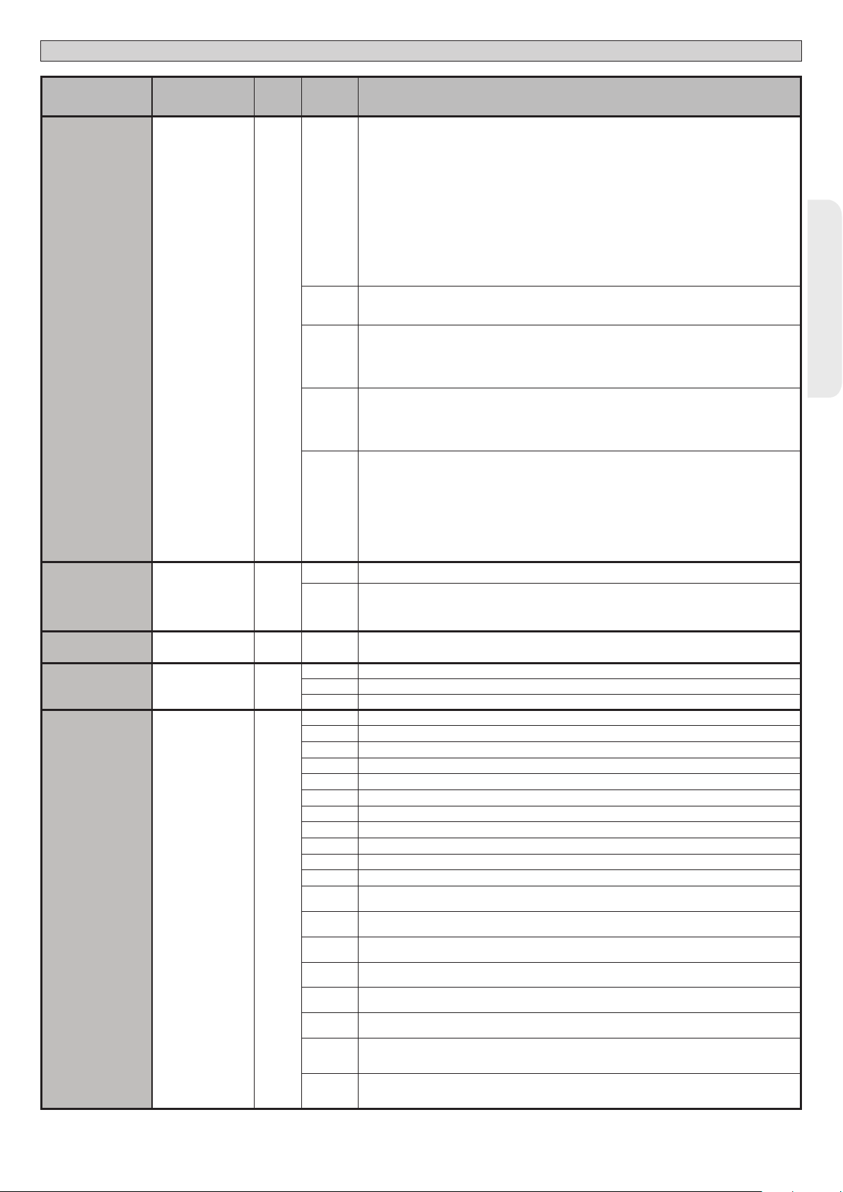
INSTALLATION MANUAL
D812865 00100_04
Logic Denition
Protection
level
SERIAL MODE
ADDRESS
chrono
EXPI1
Setting the
protection level
Serial mode
(Identies how board
is congured in a BFT
network connection).
Address 0
Time bands 0
Conguration of
EXPI1 input on
input-output expan-
sion board.
1-2
Default
0
0
1
Cross out
setting
Optional extras
used
A - The password is not required to access the programming menus
B - Enables wireless memorizing of transmitters.
Operations in this mode are carried out near the control panel and do not require access:
- Press in sequence the hidden key and normal key (T1-T2-T3-T4) of a transmitter that has already been
memorized in standard mode via the radio menu.
- Press within 10 sec. the hidden key and normal key (T1-T2-T3-T4) of a transmitter to be memorized.
The receiver exits programming mode after 10 sec.: you can use this time to enter other new transmitters
0
by repeating the previous step.
C - Enables wireless automatic addition of clones.
Enables clones generated with the universal programmer and programmed Replays to be added to the
receiver’s memory.
D - Enables wireless automatic addition of replays.
Enables programmed Replays to be added to the receiver’s memory.
E - The board’s parameters can be edited via the U-link network
A - You are prompted to enter the password to access the programming menus
1
The default password is 1234.
No change in behaviour of functions B - C - D - E from 0 logic setting
A - You are prompted to enter the password to access the programming menus
The default password is 1234.
2
B - Wireless memorizing of transmitters is disabled.
C - Wireless automatic addition of clones is disabled. No change in behaviour of functions D - E from 0 logic
setting
A - You are prompted to enter the password to access the programming menus
The default password is 1234.
3
B - Wireless memorizing of transmitters is disabled.
D - Wireless automatic addition of Replays is disabled.
No change in behaviour of functions C - E from 0 logic setting
A - You are prompted to enter the password to access the programming menus
The default password is 1234.
B - Wireless memorizing of transmitters is disabled.
C - Wireless automatic addition of clones is disabled.
4
D - Wireless automatic addition of Replays is disabled.
E - The option of editing the board’s parameters via the U-link network is disabled.
Transmitters are memorized only using the relevant Radio menu.
IMPORTANT: This high level of security stops unwanted clones from gaining access and also stops radio
interference, if any.
0 Standard SLAVE: board receives and communicates commands/diagnostics/etc.
1 Standard MASTER: board sends activation commands (START, OPEN, CLOSE, PED, STOP) to other boards.
[ ___ ]
Identies board address from 0 to119 in a local BFT network connection.
(see U-LINK OPTIONAL MODULES section)
0 Logic not enabled
1 Activates the time bands congured as timer
2 Activates the time bands congured as pedestrian timer
0 Input congured as Start E command.
1 Input congured as Start I command.
2 Input congured as Open command.
3 Input congured as Close command.
4 Input congured as Ped command.
5 Input congured as Timer command.
6 Input congured as Timer Pedestrian command.
7 Input congured as Phot (photocell) safety.
8 Input congured as Phot op safety (photocell active during opening only).
9 Input congured as Phot cl safety (photocell active during closing only).
10 Input congured as Bar safety (safety edge).
Input congured as safety Bar OP, safety edge with inversion active only while opening, if while closing
11
the movement stops.
Input congured as safety Bar CL, safety edge with inversion active only while closing, if while opening
12
the movement stops.
Input congured as Phot test safety, tested photocell. Input 3 (EXPI2) on input/output expansion board is
13
switched automatically to safety device test input, EXPFAULT1.
Input congured as Phot op test safety, tested photocell active only while opening. Input 3 (EXPI2) on input/
14
output expansion board is switched automatically to safety device test input, EXPFAULT1
Input congured as Phot cl test safety, tested photocell active only while closing. Input 3 (EXPI2) on input/
15
output expansion board is switched automatically to safety device test input, EXPFAULT1
Input congured as Bar safety, tested safety edge. Input 3 (EXPI2) on input/output expansion board is
16
switched automatically to safety device test input, EXPFAULT1.
Input congured as safety Bar OP test, safety edge with inversion active only while opening, if while closing
17
the movement stops. Input 3 (EXPI2) on input/output expansion board is switched automatically to safety
device test input, EXPFAULT1.
Input congured as safety Bar CL test, safety edge with inversion active only while closing, if while opening
18
the movement stops. Input 3 (EXPI2) on input/output expansion board is switched automatically to safety
device test input, EXPFAULT1.
ENGLISH
RIGEL 6 - 47
Page 48

INSTALLATION MANUAL
Logic Denition
EXPI2
EXPO1
EXPO2
TRAFFIC LIGHT
PREFLASHING
TRAFFIC LIGHT
RED LAMP
Steadily lit red light 0
ALWAYS ON
* Only active on FW > 1.12
Conguration of
EXPI2 input
on input-output
expansion board.
1-3
Conguration of
EXPO2 output
on input-output
expansion board
4-5
Conguration of
EXPO2 output
on input-output
expansion board
6-7
Trac light pre-
ashing
Default
0
11
11
0
Cross out
setting
Optional extras
used
0 Input congured as Start E command.
1 Input congured as Start I command.
2 Input congured as Open command.
3 Input congured as Close command.
4 Input congured as Ped command.
5 Input congured as Timer command.
6 Input congured as Timer Pedestrian command.
7 Input congured as Phot (photocell) safety.
8 Input congured as Phot op safety (photocell active during opening only).
9 Input congured as Phot cl safety (photocell active during closing only).
10
Input congured as Bar safety (safety edge).
Input congured as safety Bar OP, safety edge with inversion active only while opening, if while closing
11
the movement stops.
Input congured as safety Bar CL, safety edge with inversion active only while closing, if while opening
12
the movement stops.
0 Output congured as monostable Radio Channel.
1 Output congured as SCA (gate open light).
2 Output congured as Courtesy Light command.
3 Output congured as Zone Light command.
4 Output congured as Stair Light.
5 Output congured as Alarm.
6 Output congured as Flashing light.
7 Output congured as Latch.
8 Output congured as Magnetic lock.
9 Output congured as Maintenance.
10 Output congured as Flashing Light and Maintenance.
11 Output congured as Trac Light control with TLB board.
Not used
12
Output congured as Gate Status
13
Output congured as Bistable Radio Channel
14
Output congured as timed Radio Channel
15
0 Pre-ashing switched o.
1 Red lights ash, for 3 seconds, at start of operation.
0 Red lights o when gate closed.
1 Red lights on when gate closed.
D812865 00100_04
Radio channel control conguration
CH logic= 0 - Control congured as Start E. Operation according to STEP-BY-STEP MOV. logic. External start for trac light control.
CH logic= 1 - Control congured as Start I. Operation according to STEP-BY-STEP MOV. logic. Internal start for trac light control.
CH logic= 2 - Control congured as Open.
The command causes the leaves to open.
CH logic= 3 - Control congured as Closed.
The command causes the leaves to close.
CH logic= 4 - Control congured as Ped.
The command causes the leaf to open to the pedestrian (partial) opening position. Operation according to STEP-BY-STEP. logic
Logica CH= 5- Control congured as STOP.
The command performs a STOP
CH logic= 6 - Control congured as AUX0. (**)
The control activates the AUX0 output
CH logic= 7 - Control congured as AUX1. (**)
The control activates the AUX1 output
CH logic= 8 -Control congured as AUX2. (**)
The control activates the AUX2 output
CH logic= 9 - Control congured as AUX3. (**)
The control activates the AUX3 output
CH logic= 10 - Control congured as EXPO1. (**)
The control activates the EXPO1 output
CH logic= 11 - Control congured as EXPO2. (**)
The control activates the EXPO2 output
(**) Active only if the output is congured as Monostable Radio Channel, Courtesy Light, Zone Light, Stair Light, Bistable Radio Channel or Timed Radio Channel.
48 - RIGEL 6
Page 49

TABLE “C” RADIO MENU RADIO
Logic Description
D812865 00100_04
add 1ch
add 2ch
add 3ch
add 4ch
erase 64
erase 1
Add 1ch Key
associates the desired key with the 1nd radio channel command.
Add 2ch Key
associates the desired key with the 2nd radio channel command.
Add 3ch Key
associates the desired key with the 3nd radio channel command.
Add 4ch Key
associates the desired key with the 4nd radio channel command.
Erase List
WARNING! Erases all memorized transmitters from the receiver’s memory.
Eliminates individual radio control
Removes a radio control (if clone or replay is disabled) To select the radio control to be deleted, enter the position or press a button on the radio
control to be deleted (the position is displayed)
Read receiver code
Displays receiver code required for cloning transmitters.
INSTALLATION MANUAL
ENGLISH
RIGEL 6 - 49
Page 50

x2
MANUEL D’INSTALLATION
ACCES AUX MENUS Fig. 1
***
0---
ALT suivre le manuel
effacer 64
effacer 1
|adj1ch
|adj2ch
|adj3ch
|adj4ch
10--
touche cachee
touche cachee
touche cachee relacher
touche cachee relacher
( 0001 )
150- 1520 ok
Voir MENU PARAMÈTRES
Voir MENU LOGIQUES
relacher
touche desiree
relacher
touche desiree
touche desiree
touche desiree
o
Si supprimé
o
Si pas présent
Si clone, est désactivé
dis
Voir MENU RADIO
*** Saisie du mot de passe.
Demande avec logique Niveau Protection
congurée sur 1, 2, 3, 4
Monter
Descendre
Con firmation /
Allumage aicheur
Sortir du menu
D812865 00100_04
langue
autoset
stat
password
Pour menu
AUTOCONFIGURATION
consulter menu
simplifié
OK
vers
+
n. an
+
n. teleco
-
+
err
0---
bft . . .
+/-
OK
0000
+/-
OK
00
+/-
Liste des 30 dernières erreurs
OK
01.33
02.01
........
30.15
+/-
Code de
diagnostic
10--
Activation entrée Start externe START E
STRE
Activation entrée Start interne START I
STRI
Activation entrée OPEN
OPEN
Activation entrée CLOSE
CLS
Activation entrée piéton PED
PED
Activation entrée MINUTERIE ou activation tranche
TIME
horaire programmée
Activation entrée STOP
STOP
Activation entrée photocellule PHOT ou si congurée
comme photocellule vériée. Activation de l'entrée
PHOT
FAULT associée
Activation entrée photocellule à l'ouverture PHOT OP ou
si congurée comme photocellule vériée active unique-
PHOP
ment à l'ouverture. Activation de l'entrée FAULT associée
Activation entrée photocellule à la fermeture PHOT Cl ou
si congurée comme photocellule vériée active unique-
PHCL
ment à la fermeture. Activation de l'entrée FAULT associée
Activation entrée linteau BAR ou si congurée comme lin-
BAR
teau sensible vérié. Activation de l'entrée FAULT associée
Activation entrée linteau BAR avec inversion ACTIVE
UNIQUEMENT A L'OUVERTURE ou si configurée
baro
comme linteau sensible vérié. Activation de l'entrée
FAULT associée
Activation entrée linteau BAR avec inversion ACTIVE
UNIQUEMENT A LA FERMETURE ou si configurée
barc
comme linteau sensible vérié. Activation de l'entrée
FAULT associée
Activation entrée fin de course fermeture du moteur 1 SWC1
SWC1
Activation entrée fin de course ouverture du moteur 1 SWO1
SWO1
Activation entrée fin de course fermeture du moteur 2 SWC2
SWC2
Activation entrée fin de course ouverture du moteur 2 SWO2
SWO2
Essai photocellules échoué Vérier connexion photocellules et/ou congurations logiques
ER01
Essai linteau échoué Vérier connexion linteaux et/ou congurations logiques
ER02
Essai photocellules ouverture échoué vérier connexion photocellules et/ou conguration paramètres/logiques
ER03
Essai photocellules fermeture échoué vérier connexion photocellules et/ou conguration paramètres/logiques
ER04
Essai linteau 8k2 échoué Vérier connexion linteau et/ou congurations paramètres/logiques
ER06
Essai linteau ouverture échoué Vériez connexion linteau et/ou congurations paramètres/logiques
ER07
Essai linteau fermeture échoué Vériez connexion linteau et/ou congurations paramètres/logiques
ER08
*
Erreur essai matériel carte
ER1x
*
Inversion pour obstacle - Amperostop Vérier éventuels obstacles le long du parcours
ER3x
*
Erreur interne de contrôle supervision système.
ER7x
erreur de la conguration des entrées SAFE Vériez la bonne conguration des entrées SAFE
ERf3
Surcharge sortie serrure électrique
ERF9
*X= 0, 1, .., 9, A, B, C, D, E, F
150- 1520 prg
Description Remarque
- Vérier les connexions sur le moteur
- Problèmes matériels sur la carte (s'adresser au SAV)
Essayer d'éteindre et rallumer la carte. Si le problème persiste contacter
le service après-vente.
- Vérier les connexions de la serrure
- Serrure inadaptée
50 - RIGEL 6
Page 51

ACCES AUX MENUS Fig. 1
MANUEL D’INSTALLATION
D812865 00100_04
JOUR
dimanche 01 10-0 12-0chrono
lundi
mardi
mercredi
jeudi
vendredi|
samedi
TRANCHE
02 00-0 00-0
01 07-0 12-0
02 14-0 18-0
.... .... ....
.... .... ....
.... .... ....
01 07-0 12-0
02 14-0 18-0
.... .... ....
DÉBUT FIN
[00:00 - 24:00] [00:00 - 24:00]
FRANÇAIS
dimanche
|lundi
mardi
mercredi
jeudi
vendredi|
samedi
00 00hh-MM
[00-23]
Régler heure
[00:59]
Régler minutes
Réglage horloges
RIGEL 6 - 51
Page 52

MANUEL D’INSTALLATION
2) GÉNÉRALITÉS
Le tableau de commande RIGEL 6 est fourni par le fabricant avec un réglage
standard. Toute variation doit être congurée à l’aide du programmeur muni
d’acheur intégré ou d’un programmeur palmaire universel. La centrale supporte
complètement le protocole EELINK.
Les caractéristiques principales sont:
- Contrôle de 1 ou 2 moteurs monophasés munis de pastille thermique
- Contrôle de 1 ou 2 moteurs monophasés
Remarque: Il faut utiliser 2 moteurs du même type.
- Réglage électronique du couple
- Entrées contrôle n de course fermeture/ouverture séparées pour chaque moteur
- Entrées séparées pour les sécurités
- Gestion tranches horaires
- Détection obstacle intégrée
- Préchauage moteurs avec lecture sonde intégré
- Freinage électrodynamique réglable
- Ralentissement de la vitesse d’approche
- Récepteur radio intégré rolling-code avec clonage émetteurs.
La carte est munie d’un bornier extractible , pour faciliter les opérations d’entretien
ou le remplacement. Elle est équipée de plusieurs barrettes pré-câblées pour
faciliter la pose.
Les barrettes intéressent les bornes: 41-42, 41-43, 41-44, 41-45, 70-71, 7072, 70-74, 76-77, 76-79, 81-82, 81-84. Si vous utilisez les bornes ci-dessus ,
retirez les barrettes.
VÉRIFICATION
Le tableau RIGEL 6 accomplit le contrôle (vérication) des relais de marche et des
dispositifs de sécurité (photocellules et linteaux) avant chaque cycle d’ouverture
et de fermeture.
En cas de mauvais fonctionnement, vériez si les dispositifs branchés fonctionnent
correctement et contrôlez les câblages.
ATTENTION!: si le vantail est installé dans un lieu public ou si un mode automatique de fonctionnement est activé, nous vous recommandons d’installer deux
photocellules à 5 cm de hauteur et deux photocellules à 40-50 cm de hauteur. Par
mode automatique nous entendons n’impor te quelle commande non activée de
façon volontaire par l’utilisateur (par ex.: fonction TCA, chrono, etc..)
3) DONNÉES TECHNIQUES
Alimentation 220-230V 50/60Hz(*)
Isolation/basse tension > 2MOhm 500V
Rigidité diélectrique secteur/bt 3750V~ pendant 1 minute
Alimentation
des accessoires
24V~ (1A absorption maxi)
24V~safe
AUX0
AUX 1
Contact aligné 220-230V N.O. (80W MAX)
Contact aligné 220-230V N.O. (80W MAX)
AUX0+
AUX1+
AUX 2 Contact N.O. (MAX 220-230V~ 80W)
AUX2=
80W MAX
AUX 3 Contact N.O. (Max 24V~) 10W MAX
LOCK
Sortie pour serrure
électrique 12V :
10W MAX
Fusibles Cf. Fig. B
N° combinaisons 4 milliards
N° maxi radiocommandes
mémorisables
63
(* autres tensions disponibles à la demande)
Cycle d’utilisation continue continue 1 min. ON/
Température de
fonctionnement
Puissance maximum
moteurs 220-230V
Puissance maximum
moteurs 110-120V
-20°C/+50°C -20°C/+55°C -20°C/+50°C -20°C/+55°C
2x375 W
1x750 W
2x320 W
1x390 W
2x250 W
1x500 W
2 min. OFF
2x650 W
1x750 W
1 min. ON/
2 min. OFF
2x500 W
1x750 W
M1+M2+AUX0+AUX1+AUX2+AUX3+LOCK= 1300W MAX T=+50°C
Versions d’émetteurs utilisables :
Tous les émetteurs ROLLING CODE compatibles avec:
4) PRÉDISPOSITIONS TUYAUX Fig. A
5) CONNEXIONS DU BORNIER Fig. B
AVERTISSEMENTS - Pendant les opérations de câblage et de montage, respectez
les normes en vigueur et les principes de la bonne technique.
Les conducteurs alimentés avec des tensions diérentes doivent être séparés
physiquement entre eux ou isolés de façon adéquate avec une couche d’isolant
de 1mm d’épaisseur minimum.
Les conducteurs doivent êtres xés par un système supplémentaire à proximité
des bornes, par exemple à l’aide de bandes.
Tous les câbles de connexion doivent être maintenus à l’écart du dissipateur.
D812865 00100_04
Alimenta-
Alimentation
Borne Dénition Description
L PHASE
tion
Moteur
Aux
Fin de course
des
N NEUTRE
GND TERRE
10 MOT1 MARCHE
12 MOT1 MARCHE
14 MOT2 MARCHE
15 MOT2 COM
16 MOT2 MARCHE
20
CONTACT ALIMENTÉ 220-230V~
21
22
CONTACT ALIMENTÉ 220-230V~
23
24
25
26
27
28
29
40 Non utilisé
41 + REF SWE Commun n de course
42 SWC 1 Fin de course de fermeture du moteur 1.SWC1 (N.F.).
43 SWO 1 Fin de course d’ouverture du moteur 1.SWO1 (N.F.).
44 SWC 2 Fin de course de fermeture du moteur 2.SWC2 (N.F.).
45 SWO 2 Fin de course d’ouverture du moteur 2.SWO2 (N.F.).
50 24V-
51 24V+
accessoires
52 24 Vsafe+
AUX 2 - CONTACT LIBRE (N.O.)
AUX 3 - CONTACT LIBRE (N.O.)
AUX 0 –
AUX 1 –
LOCK 12V
Alimentation monophasée
Connexion moteur 1. Retard déphasage en fermeture.11 MOT1 COM
Connexion moteur 2. Retard déphasage en ouverture.
Remarque: si “1 MOT.ACTIF” = 1 ne branchez aucun câble sur les bornes 14-15-16
Sortie congurable AUX 0 – Défaut CLIGNOTANT
CANAL RADIO MONOSTABLE/ VOYANT PORTAIL OUVERT SCA/ Commande LUMIÈRE COURTOISIE/ Commande LUMIÈRE
ZONE/ LUMIÈRE ESCALIERS/ ALARME PORTAIL OUVERT/ CLIGNOTANT/ SERRURE ÉLECTRIQUE À DÉCLIC/ SERRURE ÉLECTRIQUE À AIMANT/ENTRETIEN/CLIGNOTANT ET ENTRETIEN / ETAT PORTAIL/CANAL RADIO BISTABLE/CANAL RADIO TEMPORISE
Consultez le tableau Conguration des sorties AUX.
Sortie congurable AUX1 – Défaut Sortie LUMIÈRE ZONE
CANAL RADIO MONOSTABLE/ VOYANT PORTAIL OUVERT SCA/ Commande LUMIÈRE COURTOISIE/ Commande LUMIÈRE
ZONE/ LUMIÈRE ESCALIERS/ ALARME PORTAIL OUVERT/ CLIGNOTANT/ SERRURE ÉLECTRIQUE À DÉCLIC/ SERRURE ÉLECTRIQUE À AIMANT/ENTRETIEN/CLIGNOTANT ET ENTRETIEN / ETAT PORTAIL/CANAL RADIO BISTABLE/CANAL RADIO TEMPORISE
Consultez le tableau Conguration des sorties AUX.
Sortie congurable AUX 2 – Défaut Sortie VOYANT PORTAIL OUVERT SCA.
CANAL RADIO MONOSTABLE/ VOYANT PORTAIL OUVERT SCA/ Commande LUMIÈRE COURTOISIE/ Commande LUMIÈRE
ZONE/ LUMIÈRE ESCALIERS/ ALARME PORTAIL OUVERT/ CLIGNOTANT/ SERRURE ÉLECTRIQUE À DÉCLIC/ SERRURE ÉLECTRIQUE
À AIMANT/ENTRETIEN/CLIGNOTANT ET ENTRETIEN / ETAT PORTAIL/CANAL RADIO BISTABLE/CANAL RADIO TEMPORISE
Consultez le tableau Conguration des sorties AUX.
Sortie congurable AUX3 – Défaut Sortie 2ème CANAL RADIO.
CANAL RADIO MONOSTABLE/ VOYANT PORTAIL OUVERT SCA/ Commande LUMIÈRE COURTOISIE/ Commande LUMIÈRE
ZONE/ LUMIÈRE ESCALIERS/ ALARME PORTAIL OUVERT/ CLIGNOTANT/ SERRURE ÉLECTRIQUE À DÉCLIC/ SERRURE ÉLECTRIQUE À AIMANT/ENTRETIEN/CLIGNOTANT ET ENTRETIEN / ETAT PORTAIL/CANAL RADIO BISTABLE/CANAL RADIO TEMPORISE
Consultez le tableau Conguration des sorties AUX.
Logique Type serrure= 0 – Sortie serrure électrique à déclic 12V
Sortie activée avec une impulsion chaque ouverture et fermeture
Logique Type serrure= 1 – Sortie serrure électrique à déclic 12V
Sortie Activée avec portail fermé et en fermeture
Sortie alimentation accessoires.
Sortie alimentation des dispositifs de sécurité vériés (émetteur photocellules et émetteur linteau sensible)
Sortie active uniquement pendant le cycle de manœuvre.
220-230V 50/60Hz(*)
(MODELE ECB)
(maxi 15W)
52 - RIGEL 6
Page 53

MANUEL D’INSTALLATION
Borne Dénition Description
D812865 00100_04
Commandes
Sécurités
Antenne
NTC
Logique Aux= 0 - Sortie CANAL RADIO MONOSTABLE
Le contact reste fermé pendant 1s au moment de l’activation du canal radio.
Logique Aux= 1 - Sortie SORTIE VOYANT PORTAIL OUVERT SCA.
Le contact reste fermé pendant l’ouverture et lorsque le vantail est ouvert, intermittent pendant la fermeture, ouvert avec le vantail fermé.
Logique Aux= 2 - Sortie commande LUMIÈRE DE COURTOISIE.
Le contact reste fermé pendant 90 secondes après la dernière manoeuvre.
Logique Aux= 3 - Sortie commande LUMIÈRE DE ZONE.
Le contact reste fermé pendant toute la durée de la manoeuvre.
Logique Aux= 4 - Sortie LUMIÈRE ESCALIERS.
Le contact reste fermé pendant 1 secondes après le début de la manœuvre.
Logique Aux= 5 - Sortie ALARME PORTAIL OUVERT.
Le contact reste fermé si le vantail reste ouvert pendant deux fois plus de temps que le TCA conguré.
Logique Aux= 6 - Sortie pour CLIGNOTANT.
Le contact reste fermé pendant la manœuvre des vantaux.
Logique Aux= 7 - Sortie pour SERRURE ÉLECTRIQUE À DÉCLIC.
Le contact reste fermé pendant 2 secondes à chaque ouverture et à chaque fermeture.
Logique Aux= 8 - Sortie pour SERRURE ÉLECTRIQUE À AIMANT.
Le contact reste fermé avec le portail fermé et pendant la manœuvre de fermeture.
Logique Aux= 9 – Sortie ENTRETIEN.
Le contact reste fermé lorsque la valeur congurée dans le paramètre Entretien est atteinte, an de signaliser la demande d’entretien.
Logique Aux= 10 – Sortie CLIGNOTANT ET ENTRETIEN.
Le contact reste fermé pendant la manœuvre des vantaux. Si la valeur congurée dans le paramètre Entretien est atteint en n de manœuvre avec le vantail fermé, 4 fois le contact se
ferme pendant 10s et s’ouvre pendant 5s pour signaler la demande d’entretien.
Logique Aux= 11 - Pas Disponible
Logique Aux= 12 - Pas Disponible
Logique AUX=13 – sortie ETAT PORTAIL
Le contact reste fermé lorsque le portail est fermé.
Logique AUX= 14 - Sortie CANAL RADIO BISTABLE
Le contact change d’état (ouvert-fermé) lors de l’activation du canal radio
Logique AUX=15 - Sortie CANAL RADIO TEMPORISE
Le contact reste fermé pendant un temps programmable lors de l’activation du canal Radio (temps sortie)
Si pendant ce temps la touche est enfoncée à nouveau, le décompte du temps redémarre.
60 Commun Commun entrées IC 1 et IC 2
61 IC 1
62 IC 2
63 Commun Commun entrées IC 3 et IC 4
64 IC 3
65 IC 4
70 Commun Commun entrées STOP, SAFE 1 et SAFE 2
71 STOP
72 SAFE 1
73 FAULT 1 Entrée de vérication des dispositifs de sécurité connectés sur le SAFE 1
74 SAFE 2
75 FAULT 2 Entrée de vérication des dispositifs de sécurité connectés sur le SAFE 2
76 Commun Commun entrées SAFE 3 et SAFE 4
77 SAFE 3
78 FAULT 3 Entrée de vérication des dispositifs de sécurité connectés sur le SAFE 3
79 SAFE 4
80 FAULT 4 Entrée de vérication des dispositifs de sécurité connectés sur le SAFE 4
81 Commun Commun entrées SAFE 5 et SAFE 6
82 SAFE 5
83 FAULT 5 Entrée de vérication des dispositifs de sécurité connectés sur le SAFE 5
84 SAFE 6
85 FAULT 6 Entrée de vérication des dispositifs de sécurité connectés sur le SAFE 6
Y ANTENNE
# SHIELD
NTC Entrée pour connexion de la sonde de température
Entrée de commande congurable 1 (N.O.) - Défaut START E
START E / START I / OPEN / CLOSE / PED / TIMER / TIMER PED
Consulter le tableau “Conguration des entrées de commande”.
Entrée de commande congurable 2 (N.O.) - Défaut PED.
START E / START I / OPEN / CLOSE / PED / TIMER / TIMER PED
Consulter le tableau “Conguration des entrées de commande”.
Entrée de commande congurable 3 (N.O.) - Défaut OPEN.
START E / START I / OPEN / CLOSE / PED / TIMER / TIMER PED
Consulter le tableau “Conguration des entrées de commande”.
Entrée de commande congurable 4 (N.O.) - Défaut CLOSE.
START E / START I / OPEN / CLOSE / PED / TIMER / TIMER PED
Consulter le tableau “Conguration des entrées de commande”.
La commande interrompt la manœuvre. (N.F.)
Si vous ne l’utilisez pas, laissez la barrette en place.
Entrée de sécurité congurable 1 (N.F.) - Défaut PHOT.
PHOT / PHOT TEST / PHOT OP / PHOT OP TEST / PHOT CL / PHOT CL TEST / BAR / BAR TEST / BAR 8K2/ B
OP/ BAR CL / BAR CL TEST / BAR 8K2 CL
Consulter le tableau “Conguration des entrées de sécurité”.
Entrée de sécurité congurable 2 (N.F.) - Défaut BAR.
PHOT / PHOT TEST / PHOT OP / PHOT OP TEST / PHOT CL / PHOT CL TEST / BAR / BAR TEST / BAR 8K2/ B
OP/ BAR CL / BAR CL TEST / BAR 8K2 CL
Consulter le tableau “Conguration des entrées de sécurité”.
Entrée de sécurité congurable 3 (N.F.) - Défaut PHOT OP.
PHOT / PHOT TEST / PHOT OP / PHOT OP TEST / PHOT CL / PHOT CL TEST / BAR / BAR TEST / BAR OP / BAR OP TEST / BAR CL / BAR CL TEST /
Consulter le tableau “Conguration des entrées de sécurité”.
Entrée de sécurité congurable 4 (N.F.) - Défaut PHOT CL.
PHOT / PHOT TEST / PHOT OP / PHOT OP TEST / PHOT CL / PHOT CL TEST / BAR / BAR TEST / BAR OP / BAR OP TEST / BAR CL / BAR CL TEST /
Consulter le tableau “Conguration des entrées de sécurité”.
Entrée de sécurité congurable 5 (N.F.) - Défaut PHOT.
PHOT / PHOT TEST / PHOT OP / PHOT OP TEST / PHOT CL / PHOT CL TEST / BAR / BAR TEST / BAR OP / BAR OP TEST / BAR CL / BAR CL TEST /
Consulter le tableau “Conguration des entrées de sécurité”.
Entrée de sécurité congurable 6 (N.F.) - Défaut BAR.
PHOT / PHOT TEST / PHOT OP / PHOT OP TEST / PHOT CL / PHOT CL TEST / BAR / BAR/TEST / BAR OP / BAR OP TEST / BAR CL / BAR CL TEST /
Consulter le tableau “Conguration des entrées de sécurité”.
Entrée de l’antenne
Utilisez une antenne syntonisée sur 433 MHz. Pour la connexion Antenne Récepteur utilisez un câble coaxial RG58. La présence de
masses métalliques près de l’antenne risque de déranger la réception radio. Si l’émetteur a une portée réduite, déplacez l’antenne
dans un endroit plus adéquat.
Conguration des sorties AUX
AR OP / BAR OP TEST / BAR 8K2
AR OP / BAR OP TEST / BAR 8K2
FRANÇAIS
RIGEL 6 - 53
Page 54

MANUEL D’INSTALLATION
Conguration des entrées de commande
Logique IC= 0 - Entrée congurée comme Start E. Fonctionnement suivant la Logique MOUVT PAS A PAS. Démarrage externe pour la gestion du sémaphore.
Logique IC= 1 - Entrée congurée comme Start I. Fonctionnement suivant la Logique MOUVT PAS A PAS. Démarrage interne pour la gestion du sémaphore.
Logique IC= 2 - Entrée congurée comme Open.
La commande accomplit une ouverture. Si l’entrée reste fermée, les vantaux restent ouverts jusqu’à l’ouverture du contact. Avec le contact ouvert l’automatisation se ferme après le
temps de TCA, s’il est activé.
Logique IC= 3 - Entrée congurée comme Close.
La commande accomplit une fermeture
Logique IC= 4 - Entrée congurée comme Ped.
La commande accomplit une ouverture piétonne, partielle. Fonctionnement suivant la logique MOUVT PAS A PAS.
Logique IC= 5 - Entrée congurée comme Timer.
Fonctionnement analogue à Open mais la fermeture est garantie même après une panne de courant.
Logique IC= 6 - Entrée congurée comme Timer Ped.
La commande accomplit une ouverture piétonne, partielle. Si l’entrée reste fermée, le vantail reste ouvert jusqu’à l’ouverture du contact. Si l’entrée reste fermée et qu’une commande
Start E, Start I ou Open est activée, une manoeuvre complète est accomplie par la suite pour rétablir l’ouverture piétonne. La fermeture est garantie même après une panne de courant.
Conguration des entrées de sécurité
Logique SAFE= 0 - Entrée congurée comme Phot, photocellule no vériées (*). (Fig. F, réf.1).
Permet de connecter les dispositifs dépourvus de contact supplémentaire de vérication. En cas d’obscurcissement, les photocellules sont actives en ouverture et en fermeture. Un
obscurcissement de la photocellule en fermeture n’inverse le mouvement que lorsque la photocellule est libérée. Si vous ne l’utilisez pas, laissez la barrette en place.
Logique SAFE= 1 - Entrée congurée comme Phot test , photocellule vériée. (Fig. F, réf.2).
Active la vérication des photocellules au début de la manoeuvre. En cas d’obscurcissement, les photocellules sont actives en ouverture et en fermeture. Un obscurcissement de la
photocellule en fermeture inverse le mouvement uniquement après le dégagement de la photocellule.
Logique SAFE = 2 - Entrée congurée comme Phot op. photocellule active uniquement à l’ouverture no vériées (*). (Fig. F, réf.1)
Permet de connecter les dispositifs dépourvus de contact supplémentaire de vérication. En cas d’obscurcissement, le fonctionnement de la photocellule en fermeture est exclu.
Pendant l’ouverture verrouille le mouvement pendant la durée de l’obscurcissement de la photocellule. Si vous ne l’utilisez pas, laissez la barrette en place.
Logique SAFE = 3 - Entrée congurée comme Phot op test. photocellule vériée active uniquement à l’ouverture (Fig. F, réf.2).
Active la vérication des photocellules au début de la manoeuvre. En cas d’obscurcissement, le fonctionnement de la photocellule en fermeture est exclu. Pendant l’ouverture verrouille le mouvement pendant la durée de l’obscurcissement de la photocellule.
Logique SAFE = 4 - Entrée congurée comme Phot cl. photocellule active uniquement à la fermeture no vériées (*). (Fig. F, réf.1)
Permet de connecter les dispositifs dépourvus de contact supplémentaire de vérication. En cas d’obscurcissement, le fonctionnement de la photocellule en ouverture est exclu. En
phase de fermeture, inverse immédiatement. Si vous ne l’utilisez pas, laissez la barrette en place.
Logique SAFE = 5 - Entrée congurée comme Phot cl test. photocellule vériée active uniquement à la fermeture (Fig. F, réf.2).
Active la vérication des photocellules au début de la manoeuvre. En cas d’obscurcissement, le fonctionnement de la photocellule en ouverture est exclu. En phase de fermeture,
inverse immédiatement.
Logique SAFE = 6 - Entrée congurée comme Bar, linteau sensibleno vériées (*). (Fig. F, réf.3)
Permet de connecter les dispositifs dépourvus de contact supplémentaire de vérication. La commande inverse le mouvement pendant 2s. Si vous ne l’utilisez pas, laissez la barrette en place
Logique SAFE = 7 - Entrée congurée comme Bar, linteau sensible vérié (Fig. F, réf.4).
Active la vérication des linteaux sensibles au début de la manoeuvre. La commande inverse le mouvement pendant 2 secondes.
Logique SAFE= 8 - Entrée congurée comme Bar 8k2 (Fig. F, réf. 5). Entrée pour linteau résistif 8K2.
La commande inverse le mouvement pendant 2 secondes.
Logique SAFE= 9 Entrée congurée comme Bar op. linteau sensible avec inversion active uniquement à l’ouverture, si activée pendant la fermeture accomplit l’arrêt de l’automatisation
(STOP) (Fig. F, réf. 3)
Permet de connecter les dispositifs dépourvus de contact supplémentaire de vérication. L’intervention en phase d’ouverture provoque l’inversion du mouvement pendant 2 sec, L’intervention en phase de fermeture provoque l’arrêt. Si vous ne l’utilisez pas, laissez la barrette en place.
Logique SAFE= 10 Entrée congurée comme Bar op. linteau sensible vérié avec inversion active uniquement à l’ouverture, si activée pendant la fermeture accomplit l’arrêt de l’automatisation (STOP) (Fig. F, réf. 4)
Active la vérication des linteaux sensibles au début de la manœuvre. L’intervention en phase d’ouverture provoque l’inversion du mouvement pendant 2 sec, L’intervention en phase
de fermeture provoque l’arrêt.
Logique SAFE= 11 Entrée congurée comme Bar 8K2 op. linteau 8K2 avec inversion active uniquement à l’ouverture, si activée pendant la fermeture accomplit l’arrêt de l’automatisation
(STOP) (Fig. F, réf. 5)
L’intervention en phase d’ouverture provoque l’inversion du mouvement pendant 2 sec, L’intervention en phase de fermeture provoque l’arrêt.
Logique SAFE= 12 Entrée congurée comme Bar cl. linteau sensible avec inversion active uniquement à la fermeture, si activée pendant l’ouverture accomplit l’arrêt de l’automatisation
(STOP) (Fig. F, réf. 3)
Permet de connecter les dispositifs dépourvus de contact supplémentaire de vérication. L’intervention en phase de fermeture provoque l’inversion du mouvement pendant 2 sec,
L’intervention en phase d’ouverture provoque l’arrêt. Si vous ne l’utilisez pas, laissez la barrette en place.
Logique SAFE= 13 Entrée congurée comme Bar cl. essai linteau sensible vérié avec inversion active uniquement à la fermeture, si activée pendant l’ouverture accomplit l’arrêt de
l’automatisation (STOP) (Fig. F, réf. 4)
Active la vérication des linteaux sensibles au début de la manœuvre. L’intervention en phase de fermeture provoque l’inversion du mouvement pendant 2 sec, L’intervention en phase
d’ouverture provoque l’arrêt.
Logique SAFE= 14 Entrée congurée comme Bar 8K2 linteau 8K2 avec inversion active uniquement à la fermeture, si activée pendant l’ouverture accomplit l’arrêt de l’automatisation
(STOP) (Fig. F, réf. 5)
L’intervention en phase de fermeture provoque l’inversion du mouvement pendant 2 sec, L’intervention en phase d’ouverture provoque l’arrêt.
(*) Si on installe des dispositifs du type D (tels que dénis par la EN12453), branchés en mode non vérié, prescrire un entretien obligatoire au moins tous
les six mois.
D812865 00100_04
54 - RIGEL 6
Page 55

MANUEL D’INSTALLATION
6) DISPOSITIFS DE SÉCURITÉ
Remarque: utiliser uniquement les dispositifs de sécurité récepteurs avec
contact en libre échange.
D812865 00100_04
6.1) DISPOSITIFS VÉRIFIÉS Fig. E
6.2) CONNEXION D’1 PAIRE DE PHOTOCELLULES NON VÉRIFIÉES Fig. C
7 ACCÈS AUX MENUS: FIG. 1
7.1) MENU PARAMÈTRES PARA
7.2 MENU LOGIQUES LOGIC TABLEAU “B” LOGIQUES
7.3) MENU RADIO radio TABLEAU “C” RADIO
- REMARQUE IMPORTANTE : MARQUEZ LE PREMIER ÉMETTEUR MÉMORISÉ
AVEC LE TIMBRE CLÉ (MASTER).
En programmation manuelle, le premier émetteur attribue le CODE CLÉ DU
RÉCEPTEUR; ce code est nécessaire pour accomplir ensuite le clonage des
émetteurs radio.
Le récepteur de bord intégré Clonix dispose également de quelques fonctionnalités
avancées importantes:
• Clonagedel’émetteurmaster(rollingcodeoucodexe)
• Clonageparsubstitutiond’émetteursdéjàintégrésaurécepteur
• Gestionbasesdedonnéesdesémetteurs
• Gestioncommunautéderécepteurs
Pour savoir comment utiliser ces fonctionnalités avancées consultez les instructions
du programmateur palmaire universel et le Guide général de programmation
des récepteurs.
Si vous utilisez une radiocommande à 4 canaux, nous vous recommandons d’en
réserver un à la fonction d’arrêt (STOP)
7.4 MENU DÉFAUT DEFAUT
Il ramène la centrale aux valeurs précongurées par DÉFAUT. Après la réinitialisation
vous devez accomplir une nouvelle AUTOCONFIGURATION.
7.5 MENU LANGUE LANGUE
Consente di impostare la lingua del programmatore a display.
7.6 MENU AUTOCONFIGURATION AUTOset
Phases d’autoconguration pour moteurs avec n de course (Fig. D1):
1 - Amenez les vantaux au niveau des ns de course de fermeture.
2 - démarrez une opération d’autoconguration en accédant au menu prévu à cet
eet, appuyez sur la touche OK pour faire démarrer la manœuvre d’ouverture
du moteur 1.
3 - Sur l’acheur le message “M1.o” apparaît.
4 - Attendez l’intervention du n de course d’ouverture pour achever la manœuvre
d’ouverture du moteur 1.
5 - La manœuvre d’ouverture du moteur 2 démarre automatiquement. Sur
l’acheur “M2.o”.
6 - Attendez l’intervention du n de course d’ouverture pour achever la manœuvre
d’ouverture du moteur 2 «CLOSE/FERME» apparaît
7 - Appuyez sur la touche OK pour faire partir la manœuvre de fermeture du
moteur 2. Sur l’acheur “M2.c”.
8 - Attendez l’intervention du n de course de fermeture pour achever la
manœuvre de fermeture du moteur 2.
9 - La manœuvre de fermeture du moteur 1 démarre automatiquement. Sur
l’acheur “M1.c ”.
10 - Attendez l’intervention du n de course de fermeture pour achever la
manœuvre de fermeture du moteur 1.
Si le temps de travail a été mémorisé correctement sur l’acheur le message
«OPEN» apparaît..
11 - Appuyez sur la touche OK pour faire démarrer le deuxième cycle pour calculer
la valeur de couple nécessaire au mouvement du vantail, sur l’acheur le
message «M1. o» apparaît.
12 - Attendez l’intervention du n de course d’ouverture pour achever la manœuvre
d’ouverture du moteur 1.
13 - La manœuvre d’ouverture du moteur 2 démarre automatiquement. Sur
l’acheur “M2.o”.
14 - Attendez l’intervention du n de course d’ouverture pour achever la manœuvre
d’ouverture du moteur 2 «CLOSE» apparaît
15 - Appuyez sur la touche OK pour faire partir la manœuvre de fermeture du
moteur 2. Sur l’acheur “M2.c”.
16 - Attendez l’intervention du n de course de fermeture pour achever la
manœuvre de fermeture du moteur 2.
17 - La manœuvre de fermeture du moteur 1 démarre automatiquement. Sur
l’acheur “M1.c ”.
18 - Attendez l’intervention du n de course de fermeture pour achever la
manœuvre de fermeture du moteur 1.
19 - Si l’autoconguration s’est achevée correctement sur l’acheur le message
«OK» apparaît; si l’autoconguration échoue, sur l’acheur le message «KO»
apparaît et l’opération doit être répétée à partir de la phase 1.
Si 1 moteur actif est conguré, les phases du moteur 2 ne sont pas exécutées.
Phases d’autoconguration pour moteurs sans n de course (Fig. D2):
1 - Amenez les vantaux au niveau des ns de course de fermeture.
2 - démarrez une opération d’autoconguration en accédant au menu prévu à cet
eet, appuyez sur la touche OK pour faire démarrer la manœuvre d’ouverture
du moteur 1.
3 - Sur l’acheur le message “M1.o” apparaît.
4 - Appuyez sur la touche OK pour terminer la manœuvre d’ouverture du moteur
1. Sur l’acheur “M2.o”.
5 - La manœuvre d’ouverture du moteur 2 démarre automatiquement.
6 - Appuyez sur la touche OK pour achever la manœuvre d’ouverture du moteur
2 «, sur l’acheur le message CLOSE/FERME» apparaît
7 - Appuyez sur la touche OK pour faire partir la manœuvre de fermeture du
moteur 2. Sur l’acheur “M2.c”.
8 - Appuyez sur la touche OK pour terminer la manœuvre de fermeture du
moteur 2. Sur l’acheur “M1.c”.
9 - La manœuvre de fermeture du moteur 1 démarre automatiquement.
10 - Appuyez sur la touche OK pour terminer la manœuvre de fermeture du
moteur 1.
Si le temps de travail a été mémorisé correctement sur l’acheur le message
«OPEN» apparaît..
11 - Appuyez sur la touche OK pour faire démarrer le deuxième cycle pour calculer
la valeur de couple nécessaire au mouvement du vantail, sur l’acheur le
message «M1. o» apparaît.
12 - Attendez l’intervention du temps de travail du moteur 1 pour achever la
manœuvre d’ouverture du moteur 1.
13 - La manœuvre d’ouverture du moteur 2 démarre automatiquement. Sur
l’acheur “M2.o”.
TABLEAU “A” PARAMÈTRES
14 - Attendez l’intervention du temps de travail du moteur 2 pour achever la
manœuvre d’ouverture du moteur 2 , sur l’acheur le message «CLOSE»
apparaît
15 - Appuyez sur la touche OK pour faire partir la manœuvre de fermeture du
moteur 2. Sur l’acheur “M2.c”.
16 - Attendez l’intervention du temps de travail du m oteur 2 pour achever la
manœuvre de fermeture du moteur 2.
17 - La manœuvre de fermeture du moteur 1 démarre automatiquement. Sur
l’acheur “M1.c ”.
18 - Attendez l’intervention du temps de travail du moteur 1 pour achever la
manœuvre de fermeture du moteur 1.
19 - Si l’autoconguration s’est achevée correctement sur l’acheur le message
«OK» apparaît; si l’autoconguration échoue, sur l’acheur le message «KO»
apparaît et l’opération doit être répétée à partir de la phase 1.
Si 1 moteur actif est conguré, les phases du moteur 2 ne sont pas exécutées.
Pendant cette phase, il est important d’éviter l’obscurcissement des photocellules,
l’intervention des sécurités et d’utiliser les commandes START, STOP, OPEN,
CLOSE et l’acheur.
Au terme de cette opération, la centrale de commande aura automatiquement
conguré les valeurs optimales des paramètres.. Vériez-les et modiez-les,
le cas échéant, de la façon décrite dans la programmation.
ATTENTION !! Vériez si la valeur de la force de choc mesurée dans les
points prévus par la norme EN12445 est inférieure à celle indiquée
dans la norme EN 12453.
Les forces de choc doivent être limitées à l’aide de linteaux actifs
conformes à la norme EN12978
Attention !! Pendant l’autoréglage la fonction de détection des obstacles n’étant pas active le monteur doit contrôler le mouvement de
l’automatisation et empêcher que des personnes ou des choses ne
s’approchent ou ne stationnent dans le rayon d’action de l’automatisation.
7.7) SÉQUENCE VÉRIFICATION INSTALLATION
1. Appliquez des dispositifs de protection sensibles à la pression ou
électrosensibles (par exemple un linteau actif)
2. Procédez à l’AUTOCONFIGURATION (*)
3. Vériez les forces de choc: si elles respectent les limites allez au point 5 de la
séquence, en cas contraire
4. N’autorisez la manutention de l’actionnement qu’en mode Homme présent
5. Vériez si tous les dispositifs de détection de présence dans l’aire de manœuvre
fonctionnement correctement
(*) Avant d’accomplir l’auto-conguration assurez-vous d’avoir accompli correctement toutes les opérations de montage et de mise en sécurité, prescrites
par les avertissements de montage du manuel de la motorisation et d’avoir
conguré les paramètres de force d’ouverture/fermeture, ralentissement et
temps de ralentissement..
7.8 MENU STATISTIQUES
Permet d’acher la version de la carte, le nombre total de manœuvres (en
centaines), le nombre de radiocommandes mémorisées et les 30 dernières erreurs
(les 2 premiers chires indiquent la position, les 2 derniers le code d’erreur).
L’erreur 01 est la plus récente.
7.9) MENU MOT DE PASSE
Permet de congurer un mot de passe pour la programmation de la carte via
le réseau U-link.
Si la logique NIVEAU PROTECTION est congurée sur 1,2,3,4 le système demande
le mot de passe pour accéder aux menus de programmation. Après l’échec de
10 tentatives d’accès consécutives il faut attendre 3 minutes avant d’essayer è
nouveau. En cas de tentative d’accès pendant ce délai l’acheur montre BLOC.
Le mot de passe par défaut est 1234.
7.10) MENU CHRONO Fig.I
Permet de programmer le fonctionnement par tranches horaires.
On peut programmer un maximum de deux tranches horaires quotidiennes
pendant lesquelles le portail reste ouvert (lundi dimanche).
Les vantaux s’ouvrent pendant la tranche horaire et restent ouverts jusqu’au terme de la tranche horaire.
8) PPRESSION FIN DE COURSE FERMETURE Fig. F Réf. A-B
DIRECTION OUVERTURE Fig. F Réf. C-D
9) CONNEXION AVEC CARTES D’EXPANSION ET PROGRAMMATEUR PALMAIRE
UNIVERSELLE (Fig. G) Consultez le manuel intéressé.
10) MODULES U-LINK EN OPTION
Consultez les instructions des modules U-link.
L’utilisation de certains modules implique une réduction de la portée radio.
Adaptez l’installation avec une antenne accordée sur 433 MHz
11) RÉTABLISSEMENT DES CONFIGURATIONS D’USINE (Fig. H)
ATTENTION ramène la centrale aux valeurs précongurées en usine et toutes
les radiocommandes mémorisées sont eacées.
ATTENTION ! Toute erreur de conguration peut causer des préjudices aux
personnes, aux animaux et aux biens.
- Mettez hors tension la carte (Fig. H réf. 1)
- Ouvrez l’entrée Stop et appuyez en même temps sur les touches – et OK (Fig.
H réf. 2)
- Mettez sous tension la carte (Fig. H réf. 3)
- L’acheur montre RST, dans les 3 secondes qui suivent conrmez en appuyant
sur la touche OK (Fig. H réf. 4)
- Attendez que la procédure s’achève (Fig. H réf. 5)
- Procédure achevée (Fig. H réf. 6)
ATTENTION : Vériez si la valeur de la force de choc mesurée dans les
points prévus par la norme EN12445 est inférieure à celle indiquée
dans la norme EN 12453.
Les forces de choc peuvent être réduites à l’aide de rebords déformables.
Pour obtenir un meilleur résultat, nous vous conseillons d’accomplir l’autoconguration avec les moteurs au repos (c’est-à-dire alors qu’ils ne sont pas
surchaués par un grand nombre de manœuvres consécutives).
FRANÇAIS
RIGEL 6 - 55
Page 56
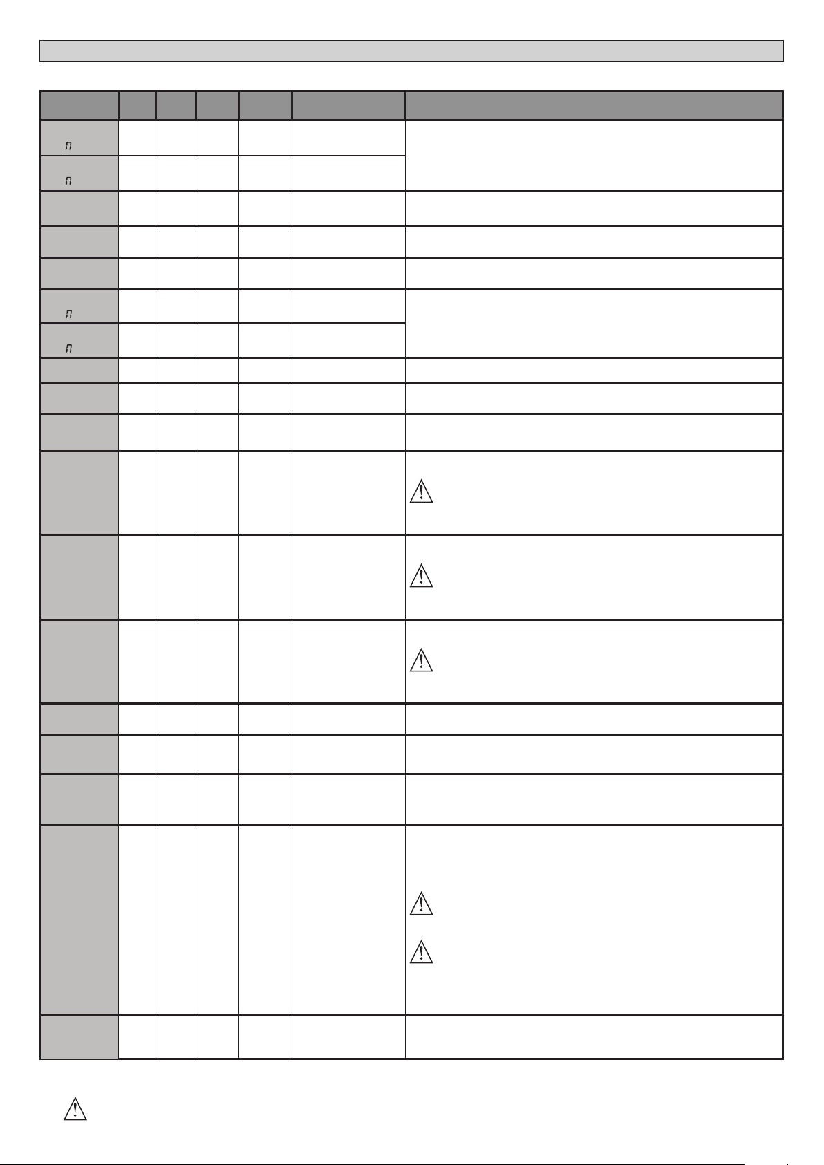
TABLEAU “A” - MENU PARAMÈTRES - (param)
Paramètre mini maxi
t. trav.
ot.1
t. trav.
ot.2
ouv.
partielle
T RETARD
OUV
T RETARD
FER
t. rall
ot1
t. rall
ot2
TCA
T.EVAC.SEM
t.sortie
FORCE OUV
FORCE FERM
force raL
frein
frein
urg.
prer.
3.0 180.0 60.0
3.0 180.0 60.0
3 90 6 Ouverture partielle M1 [s] Temps d’ouverture partielle à la suite de l’activation de la commande piétonne PED du moteur M1
0 10 3
0 25 3
0 30 0
0 30 0
0 120 10
1 180 40
1 240 10
1 99 50
1 99 50
1 99 50
0 99 0
0 99 60
0 99 30
Dé-
faut
Person-
nels
MANUEL D’INSTALLATION
Dénition Description
Temps de travail
moteur 1 [s]
Temps de travail
moteur 2 [s]
Temps retard ouverture
moteur 2 [s]
Temps retard fermeture
moteur 1 [s]
Temps de
ralentissement
moteur 1 [s]
Temps de
ralentissement
moteur 2 [s]
Temps fermeture
automatique [s]
Temps évacuation zone
du sémaphore [s]
Temps d’activation de la
sortie temporisée
[s]
Force vantail/vantaux
à l’ouverture [%]
Force vantail/vantaux
à la fermeture [%]
Force des moteurs en
ralentissement
[%]
Freinage
[%]
Freinage d’urgence
[%]
Préchauage
[%]
Congure la valeur du temps de travail en secondes pour le moteur 1/2
A la n d’une autoconguration est congurée avec la valeur réelle de travail du moteur
Temps de retard à l’ouverture du moteur 2 par rapport au moteur 1
Temps de retard à la fermeture du moteur 1 par rapport au moteur 2
Congurer le temps de ralentissement pendant l’approche La durée du ralentissement est
soustraite au temps de travail.
REMARQUE: N’utilisez cette fonction qu’en présence de n de course.
REMARQUE: Ne pas utiliser avec les moteurs hydrauliques.
(***)
Temps d’attente avant la fermeture automatique
Temps d’évacuation de la zone intéressée par la circulation réglée par le sémaphore.
Durée d’activation de la sortie canal temporisée en secondes
Force exercée par le(s) vantail(vantaux) à l’ouverture.
Représente le pourcentage de force fournie à régime par rapport à la valeur maximum
ATTENTION : A une incidence directe sur la force de choc: vérier si la valeur
congurée permet de respecter les règlements de sécurité en vigueur (*)
Installez des dispositifs de sécurité anti-écrasement (**).
(***)
Force exercée par le(s) vantail(vantaux) à la fermeture.
Représente le pourcentage de force fournie à régime par rapport à la valeur maximum
ATTENTION : A une incidence directe sur la force de choc: vérier si la valeur
congurée permet de respecter les règlements de sécurité en vigueur (*)
Installez des dispositifs de sécurité anti-écrasement (**).
(***)
Force exercée par le(s) vantail(vantaux) au ralentissement.
Représente le pourcentage de force fournie en ralentissement.
ATTENTION : A une incidence directe sur la force de choc: vérier si la valeur
congurée permet de respecter les règlements de sécurité en vigueur (*)
Installez des dispositifs de sécurité anti-écrasement (**).
(***)
Congurer la valeur du freinage entre 0% (mini) et 99% (maxi), en tenant compte du poids du
portail et des sollicitations mécaniques présentes.
Congurer la valeur entre 0% (mini) et 99% (maxi) du freinage d’urgence, qui s’accomplit en
activant les commandes de sécurité présentes sur les entrées congurées comme linteau
sensible BAR.
Introduire la valeur en pour cent de courant de 0 (préchauage désactivé) à 99% que l’on peut
faire passer dans les enroulements des moteurs pour les maintenir à la bonne température.
REMARQUE: la sonde de température NTC doit être branchée.
La sonde doit être placée et xée au contact du moteur pour détecter la température extérieure
Permet d’activer la détection des obstacles
La fonction est désactivée si le paramètre est conguré sur 0, si vous le congurez sur une
valeur de 1 à la valeur maximum vous pouvez augmenter la sensibilité aux obstacles (valeur
maxi=sensibilité maxi).
Ne fonctionne qu’avec les ns de course
D812865 00100_04
sens.obst.
Entretien
0 99 0 Sensibilité aux obstacles
0 250 0
Programmation du nom-
bre de manœuvres seuil
d’entretien [en centaines]
ATTENTION : Cette fonction de détection des obstacles ne garantit pas le respect
des normes de sécurité en vigueur (*). Pour respecter les normes de sécurité en
vigueur, montez des dispositifs de sécurité anti-écrasement appropriés (**).
ATTENTION: Le système ne détecte les obstacles que si le vantail est arrêté, il ne
détecte pas les obstacles qui freinent le vantail sans l’arrêter.
La détection n’a lieu que si le vantail qui rencontre un obstacle se déplace à la vitesse
normale. Pendant le ralentissement l’obstacle n’est pas détecté.
(***)
Permet de congurer un nombre de manœuvres après lequel la demande d’entretien est
signalée sur la sortie AUX congurée comme Entretien ou Clignotant et Entretien.
(*) Dans l’Union européenne appliquer la EN12453 pour les limites de force et la EN12445 pour la méthode de mesure.
(**) Les forces de choc doivent être limitées à l’aide de linteaux actifs conformes à la norme EN12978
(***)
ATTENTION : Si vous modiez le paramètre vous devez procéder à une autoconguration si la fonction “sensibilité obstacle” est active.
56 - RIGEL 6
Page 57

TABLEAU “B” - LOGIQUES - (LOGIC)
D812865 00100_04
Logique Dénition
TCA
FE.RAP
MOUVT
Temps fermeture
Fermeture rapide 0
Mouvement pas
PAS A PAS
PREAL
HOMME MORTE
Homme-présent 0
BL.IMP.OUV
BL.IMP.TCA
BLI.FE
COUP BEL.OUV
COUP BEL.FE
impulsions en
impulsions à la
Coup de bélier à
Coup de bélier à
MAINT.BLOC
PRESS SWC
1 MOT.ACTIF
Pression n de
course fermeture
1 Moteur actif 0
INV.SENS.OUV
automatique
à pas
Préalarme 0
Verrouillage
impulsions à
l’ouverture
Verrouillage
TCA.
Verrouillage
fermeture
l’ouverture
la fermeture
Maintien
verrouillage
Inversion
direction de
l'ouverture
Défaut
0
0
0
0
0
0
0
0
0
0
MANUEL D’INSTALLATION
Cochez le
réglage
accompli
0 Logique non active
1 Active la fermeture automatique
0 Logique non active
1 Se ferme 3s après le dégagement des photocellules avant d’attendre la n du TCA conguré.
Les entrées congurées comme Start E, Start I,
0
Ped fonctionnement avec la logique 4 pas.
Les entrées congurées comme Start E, Start
I, Ped fonctionnement avec la logique 3 pas.
1
L'impulsion pendant la phase de fermeture
inverse le mouvement.
Les entrées congurées comme Start E, Start
2
I, Ped fonctionnement avec la logique 2 pas. A
chaque impulsion le mouvement est inverti.
0 Le clignotant s’éclaire au moment où le(s) moteur(s) démarre(nt).
1 Le clignotant s'allume pendant 3 secondes environ avant le démarrage du(des) moteur(s).
0 Fonctionnement à impulsions
Fonctionnement avec Homme présent.
L’entrée 61 est congurée comme OPEN UP.
L’entrée 62 est congurée comme CLOSE UP.
1
La manœuvre continue tant que les touches de commande OPEN UP ou CLOSE UP restent enfoncées.
ATTENTION : les dispositifs de sécurité ne sont pas actifs.
Fonctionnement Homme présent Urgence. Normalement fonctionnement à impulsions.
Si la carte échoue aux essais de sécurité (photocellule ou linteau, Er0x) 3 fois de suite, le fonctionnement
Homme présent actif est activé jusqu’à ce que les touches OPEN UP ou CLOSE UP soient libérées.
2
L’entrée 61 est congurée comme OPEN UP.
L’entrée 62 est congurée comme CLOSE UP.
ATTENTION : avec Homme présent Urgence les dispositifs de sécurité ne sont pas actifs.
0 L'impulsion des entrées congurées come Start E, Start I, Ped prend eet pendant l'ouverture.
1 L'impulsion des entrées congurées come Start E, Start I, Ped ne prend pas eet pendant l'ouverture.
0 L'impulsion des entrées congurées come Start E, Start I, Ped prend eet pendant l'ouverture TCA.
1 L'impulsion des entrées congurées come Start E, Start I, Ped ne prend pas eet pendant la pause TCA.
0 L'impulsion des entrées congurées come Start E, Start I, Ped prend eet pendant la fermeture.
1 L'impulsion des entrées congurées come Start E, Start I, Ped ne prend pas eet pendant la fermeture.
0 Logique non active
Avant d’accomplir l’ouverture le portail pousse pendant environ 2 secondes en fermeture. Cela permet à la
1
serrure électrique de se décrocher plus facilement.
IMPORTANT - Ne pas utiliser cette fonction en l’absence de butées d’arrêt mécaniques adéquates.
0 Logique non active
Avant d’accomplir la fermeture le portail pousse pendant 2 secondes environ en ouverture. Cela permet à la
1
serrure électrique de se décrocher plus facilement.
IMPORTANT - Ne pas utiliser cette fonction en l’absence de butées d’arrêt mécaniques adéquates.
0 Logique non active
Si les moteurs restent arrêtés en position d'ouverture complète ou de fermeture complète pendant plus d’une
heure, ils sont activés pendant 3 secondes environ dans le sens de la butée Cette opération s’accomplit toutes
les heures.
1
N.B.: Cette fonction permet de compenser, dans les moteurs oléodynamiques, la réduction éventuelle du
volume de l'huile causée par la chute de température pendant les pauses prolongées, par exemple la nuit, ou
due à des fuites internes.
IMPORTANT - Ne pas utiliser cette fonction en l’absence de butées d’arrêt mécaniques adéquates.
Le mouvement n’est arrêté que par l’intervention du n de course; dans ce cas il faut régler très précisément
0
l’intervention du n de course de fermeture (Fig. G Réf. B).
A utiliser en présence de butée mécanique de fermeture.
Cette fonction active la pression des vantaux sur la butée mécanique, sans que celle-ci ne soit considérée
comme un obstacle par le capteur Amperostop.
1
La tige continue donc sa course pendant quelques secondes supplémentaires, après l’interception du n de
course de fermeture ou jusqu’à l’arrêt mécanique. De la sorte en anticipant légèrement l’intervention du n de
course de fermeture, on obtient l’arrêt parfait des vantaux sur la butée d’arrêt (Fig. G Réf.A).
0 Les deux moteurs (2 vantaux) sont actifs.
1 Seul le moteur 1 (1 vantail) est actif.
0 Fonctionnement standard (Fig. G Réf.C).
1 Le sens de l’ouverture est inverti par rapport au fonctionnement standard (Fig. G Réf.D).
Options
FERMÉE
EN
FERMETURE
OUVERTE
EN
OUVERTURE
APRÈS STOP
Mouvement pas à pas
2 PAS 3 PAS 4 PAS
OUVRE OUVRE
FERME FERME
FERME
STOP + TCA
OUVRE OUVRE OUVRE
OUVRE
STOP
STOP + TCA
FRANÇAIS
RIGEL 6 - 57
Page 58

MANUEL D’INSTALLATION
Logique Dénition
Conguration
SAFE 1
SAFE 2
SAFE 3
SAFE 4
SAFE 5
SAFE 6
IC 1
IC 2
IC 3
IC 4
1ch
2ch
3ch
4ch
AUX 0
AUX 1
AUX 2
AUX 3
de l’entrée de
sécurité SAFE 1.
72
Conguration
de l’entrée de
sécurité SAFE 2.
74
Conguration
de l’entrée de
sécurité SAFE 3.
77
Conguration
de l’entrée de
sécurité SAFE 4.
79
Conguration
de l’entrée de
sécurité SAFE 5.
82
Conguration
de l’entrée de
sécurité SAFE 6.
84
Conguration
de l'entrée de
commande IC 1.
61
Conguration
de l'entrée de
commande IC 2.
62
Conguration
de l'entrée de
commande IC 3.
64
Conguration
de l'entrée de
commande IC 4.
65
Conguration de
la commande 1
canal radio
Conguration de
la commande 2
canal radio
Conguration de
la commande 3
canal radio
Conguration de
la commande 4
canal radio
Conguration de
la sortie AUX 0.
20-21
Conguration de
la sortie AUX 1.
22-23
Conguration de
la sortie AUX 2.
24-25
Conguration de
la sortie AUX 3.
26-27
Cochez le
Défaut
réglage
accompli
0
6
2
4
0
6
0
4
2
3 6 Entrée congurée comme Timer Piéton
0
9
2
5
6
3
1
0
0 Entrée congurée comme Phot, photocellule.
1 Entrée congurée comme Phot test , photocellule vériée.
2 Entrée congurée comme Phot op. photocellule active uniquement à l’ouverture.
3 Entrée congurée comme Phot op test. photocellule vériée active uniquement à l’ouverture.
4 Entrée congurée comme Phot cl. photocellule active uniquement à la fermeture.
5 Entrée congurée comme Phot cl test. photocellule vériée active uniquement à la fermeture.
6 Entrée congurée comme Bar, linteau sensible
7 Entrée congurée comme Bar, linteau sensible vériée
8 Entrée congurée comme Bar 8k2 (Pas active sur SAFE 3,4,5,6).
Entrée congurée comme Bar OP, linteau sensible avec inversion active uniquement à l’ouverture. A la fermeture
9
on obtient l’arrêt du mouvement.
Entrée congurée comme Bar OP TEST, linteau sensible vérié avec inversion active uniquement à l’ouverture. A
10
la fermeture on obtient l’arrêt du mouvement.
Entrée congurée comme Bar OP 8K2, linteau sensible avec inversion active uniquement à l’ouverture. A la fer-
11
meture on obtient l’arrêt du mouvement.
(Pas active sur SAFE 3,4,5,6).
Entrée congurée comme Bar Cl, linteau sensible avec inversion active uniquement à la fermeture. A l’ouverture
12
on obtient l’arrêt du mouvement.
Entrée congurée comme Bar Cl TEST, linteau sensible vérié avec inversion active uniquement à la fermeture. A
13
l’ouverture on obtient l’arrêt du mouvement.
Entrée congurée comme Bar Cl, 8K2 linteau sensible avec inversion active uniquement à la fermeture. A l’ou-
14
verture on obtient l’arrêt du mouvement.
(Pas active sur SAFE 3,4,5,6).
0 Entrée congurée comme Start E
1 Entrée congurée comme Start I
2 Entrée congurée comme Open.
3 Entrée congurée comme Close.
4 Entrée congurée comme Ped.
5 Entrée congurée comme Timer.
0 Commande radio congurée comme START E.
1 Commande radio congurée comme Start I.
2 Commande radio congurée comme Open.
3 Commande radio congurée comme Close
4 Commande radio congurée comme Ped
5 Commande radio congurée comme STOP
6 Commande radio congurée comme AUX0 **
7 Commande radio congurée comme AUX1**
8 Commande radio congurée comme AUX2**
9 Commande radio congurée comme AUX3**
10 Commande radio congurée comme EXPO1**
11 Commande radio congurée comme EXPO2**
0 Sortie congurée comme Canal radio monostable.
1 Sortie congurée comme SCA, Voyant portail ouvert.
2 Sortie congurée comme commande Lumière de courtoisie
3 Sortie congurée comme commande Lumière de zone
4 Sortie congurée comme Lumières escaliers.
5 Sortie congurée comme Alarme.
6 Sortie congurée comme Clignotant.
7 Sortie congurée comme Serrure à déclic.
8 Sortie congurée comme Serrure à aimant.
9 Sortie congurée comme Entretien
10 Sortie congurée comme Clignotant et Entretien.
11 Non utilisé
12 Non utilisé
13 Sortie congurée comme Etat portail
14 Sortie congurée comme Canal radio bistable.
15 Sortie congurée comme Canal radio temporisé.
Options
D812865 00100_04
58 - RIGEL 6
Page 59

MANUEL D’INSTALLATION
D812865 00100_04
Logique Dénition
SERRURE
CODE FIXE
Niveau de
protection
MODE SERIE
ADRESSE
chrono
EXPI1
Défaut
Type de serrure
28-29
Code xe 0
Conguration
du niveau de
protection
Mode série
(Indique comment
congurer la
carte dans une
connexion de
réseau BFT.)
Adresse 0
Tranches horaires 0
Conguration
de l'entrée EXPI1
dans la carte
d'expansion des
entrées/sorties
1-2
0
0
0
1
Cochez le
réglage
Options
accompli
0 Sortie congurée pour serrure électrique à déclic 12V
1 Sortie congurée pour serrure électrique à aimant 12V
Le récepteur est conguré pour le fonctionnement en mode code rolling.
0
Les Clones à Code xe ne sont pas acceptés.
Le récepteur est conguré pour le fonctionnement en mode code xe.
1
Les Clones à Code xe sont acceptés.
A – Le mot de passe n’est pas demandé pour accéder au menu de programmation
B - Active la mémorisation via radio des radiocommandes:
Ce mode, accompli à proximité du tableau de commande, ne demande aucun accès.
- Appuyez en séquence sur la touche cachée et sur la touche normale (T1-T2-T3-T4) d’une radiocommande déjà
mémorisée en mode standard à travers le menu radio.
- Appuyez dans les 10 secondes sur la touche cachée et sur la touche normale (T1-T2-T3-T4) d’une radiocom-
mande à mémoriser.
0
Le récepteur sort du mode programmation après 10 secondes, durant ce laps de temps vous pouvez ajouter de
nouvelles radiocommandes en répétant le point précédent.
C – Active la saisie automatique via radio des clones.
Permet aux clones générés avec le programmateur universel et aux replay programmés de s’ajouter à la
mémoire du récepteur.
D – Active la saisie automatique via radio des replay.
Permet au Replay programmés de s’ajouter à la mémoire du récepteur.
E – Il est impossible de modier les paramètres de la carte à travers le réseau U-Link
A – Le mot de passe est demandé pour accéder au menu de programmation.
1
Le mot de passe par défaut est 1234.
Les fonctions B – C - D- E restent inchangées par rapport au fonctionnement 0.
A – Le mot de passe est demandé pour accéder au menu de programmation.
Le mot de passe par défaut est 1234.
2
B - Désactive la mémorisation via radio des radiocommandes:
C – Désactive la saisie automatique via radio des clones.
Les fonctions D- E restent inchangées par rapport au fonctionnement 0.
A – Le mot de passe est demandé pour accéder au menu de programmation.
Le mot de passe par défaut est 1234.
3
B - Désactive la mémorisation via radio des radiocommandes:
D– Désactive la saisie automatique via radio des Replay.
Les fonctions C- E restent inchangées par rapport au fonctionnement 0.
A – Le mot de passe est demandé pour accéder au menu de programmation.
Le mot de passe par défaut est 1234.
B - Désactive la mémorisation via radio des radiocommandes:
C – Désactive la saisie automatique via radio des clones.
4
D – Désactive la saisie automatique via radio des Replay.
E – Il devient impossible de modier les paramètres de la carte à travers le réseau U-Link
Les radiocommandes ne sont mémorisées qu’en utilisant le menu Radio prévu à cet eet.
IMPORTANT: Ce niveau de sécurité élevé interdit l’accès aux clones non-désirés et aux parasites radio éventuel-
lement présents.
0 SLAVE standard: la carte reçoit et communique commandes/diagnostics/etc..
MASTER standard: la carte envoie les commandes d'activation (START, OPEN, CLOSE, PED, STOP) à d'autres
1
cartes.
[ ___ ]
Identie l'adresse de 0 à 119 d'une carte dans une connexion de réseau BFT locale.
(cf. paragraphe x MODULES EN OPTION U-LINK)
0 Logique non active
1 Active les tranches horaires congurées comme minuterie
2 Active les tranches horaires congurées comme minuterie piétonne
0 Entrée congurée comme commande Start E.
1 Entrée congurée comme commande Start I.
2 Entrée congurée comme commande Open.
3 Entrée congurée comme commande Close.
4 Entrée congurée comme commande Ped.
5 Entrée congurée comme commande Timer.
6 Entrée congurée comme commande Timer Piéton.
7 Entrée congurée comme sécurité Phot, photocellule.
8 Entrée congurée comme sécurité Phot op. photocellule active uniquement à l'ouverture.
9 Entrée congurée comme sécurité Phot cl. photocellule active uniquement à la fermeture.
10 Entrée congurée comme sécurité Bar, linteau sensible
Entrée congurée comme sécurité Bar OP, linteau sensible avec inversion active uniquement à l’ouverture; à la
11
fermeture on obtient l’arrêt du mouvement.
Entrée congurée comme sécurité Bar CL, linteau sensible avec inversion active uniquement à la fermeture; à
12
l’ouverture on obtient l’arrêt du mouvement.
Entrée congurée comme sécurité Phot test , photocellule vériée. L’entrée 3 (EXP12) de la carte d’expansion
13
des entrées/sorties est commutée automatiquement en entrée vérication dispositifs de sécurité EXPFAULT1..
Entrée congurée comme sécurité Phot op test, photocellule vériée active uniquement à l’ouverture. L’entrée 3
14
(EXPI2 ) de la carte d’expansion entrées/sorties est commutée automatiquement en entrée vérication dispositifs
de sécurité EXPFAULT1,
Entrée congurée comme sécurité Phot cl test, photocellule vériée active uniquement à la fermeture. L’entrée 3
15
(EXPI2 ) de la carte d’expansion entrées/sorties est commutée automatiquement en entrée vérication dispositifs
de sécurité EXPFAULT1,
Entrée congurée comme sécurité Bar, linteau sensible vérié L’entrée 3 (EXP12) de la carte d’expansion des entrées/
16
sorties est commutée automatiquement en entrée vérication dispositifs de sécurité EXPFAULT1..
Entrée congurée comme sécurité Bar OP test, linteau sensible vérié avec inversion active uniquement à l’ou-
17
verture; à la fermeture on obtient l’arrêt du mouvement. L’entrée 3 (EXP12) de la carte d’expansion des entrées/
sorties est commutée automatiquement en entrée vérication dispositifs de sécurité EXPFAULT1..
Entrée congurée comme sécurité Bar CL test, linteau sensible avec inversion active uniquement à la fermeture;
18
à l’ouverture on obtient l’arrêt du mouvement. L’entrée 3 (EXP12) de la carte d’expansion des entrées/sorties est
commutée automatiquement en entrée vérication dispositifs de sécurité EXPFAULT1..
.
.
FRANÇAIS
RIGEL 6 - 59
Page 60
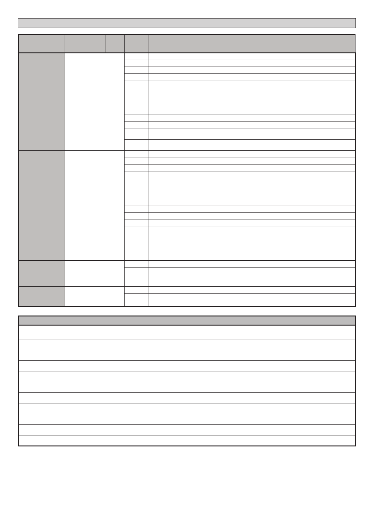
MANUEL D’INSTALLATION
Logique Dénition
de l'entrée EXPI2
EXPI2
EXPO1
EXPO2
FEU DE
SIGNALISATION
d'expansion des
Conguration de
d'expansion des
Conguration de
d'expansion des
Pré-clignotement
PRE-
CLIGNOTEMENT
FEU DE
SIGNALISATION
Sémaphore rouge
ROUGE FIXE
Conguration
dans la carte
entrées/sorties
1-3
l'entrée EXPO2
dans la carte
entrées/sorties
4-5
l'entrée EXPO2
dans la carte
entrées/sorties
6-7
sémaphore
xe
Défaut
0
11
11
0
0
Cochez le
réglage
Options
accompli
0 Entrée congurée comme commande Start E.
1 Entrée congurée comme commande Start I.
2 Entrée congurée comme commande Open.
3 Entrée congurée comme commande Close.
4 Entrée congurée comme commande Ped.
5 Entrée congurée comme commande Timer.
6 Entrée congurée comme commande Timer Piéton.
7 Entrée congurée comme sécurité Phot, photocellule.
8 Entrée congurée comme sécurité Phot op. photocellule active uniquement à l'ouverture.
9 Entrée congurée comme sécurité Phot cl. photocellule active uniquement à la fermeture.
10 Entrée congurée comme sécurité Bar, linteau sensible
Entrée congurée comme sécurité Bar OP, linteau sensible avec inversion active uniquement à l’ouverture; à la
11
fermeture on obtient l’arrêt du mouvement.
Entrée congurée comme sécurité Bar CL, linteau sensible avec inversion active uniquement à la fermeture; à
12
l’ouverture on obtient l’arrêt du mouvement.
0 Sortie congurée comme Canal radio monostable.
1 Sortie congurée comme SCA, Voyant portail ouvert.
2 Sortie congurée comme commande Lumière de courtoisie
3 Sortie congurée comme commande Lumière de zone
4 Sortie congurée comme Lumières escaliers.
5 Sortie congurée comme Alarme.
6 Sortie congurée comme Clignotant.
7 Sortie congurée comme Serrure à déclic.
8 Sortie congurée comme Serrure à aimant.
9 Sortie congurée comme Entretien
10 Sortie congurée comme Clignotant et Entretien.
11 Sortie congurée comme Gestion sémaphore avec carte TLB.
12 Non utilisé
13 Sortie congurée comme Etat portail
14 Sortie congurée comme Canal radio bistable.
15 Sortie congurée comme Canal radio temporisé.
0 Pré-clignotement exclu.
1 Lumières rouges clignotantes, pendant 3 secondes au début de la manoeuvre.
0 Lumières rouges éteintes avec le portail fermé.
1 Lumières rouges éclairées avec le portail fermé.
D812865 00100_04
Conguration des commandes canal radio
Logique CH= 0 - Commande congurée commeStart E. Fonctionnement suivant la Logique MOUVT PAS A PAS. Démarrage externe pour la gestion du sémaphore.
Logique CH= 1 - Commande congurée comme Start I. Fonctionnement suivant la Logique MOUVT PAS A PAS. Démarrage interne pour la gestion du sémaphore.
Logique CH= 2 - Commande congurée comme Open.
La commande accomplit une ouverture.
Logique CH= 3 - Commande congurée commeClose.
La commande accomplit une fermeture.
Logique CH= 4 - Commande congurée comme Ped.
La commande accomplit une ouverture piétonne, partielle. Fonctionnement suivant la logique MOUVT PAS A PAS.
Logique CH= 5- Commande congurée commeSTOP.
La commande accomplit un Stop
Logique CH= 6- Commande congurée comme AUX0. (**)
La commande active la sortie AUX0
Logique CH= 7- Commande congurée comme AUX1. (**)
La commande active la sortie AUX1
Logique CH= 8- Commande congurée comme AUX2. (**)
La commande active la sortie AUX 2
Logique CH= 9- Commande congurée comme AUX3. (**)
La commande active la sortie AUX3
Logique CH= 10- Commande congurée comme EXPO1. (**)
La commande active la sortie EXPO1
Logique CH= 11- Commande congurée comme EXPO2. (**)
La commande active la sortie EXPO2
(**) Active uniquement si la sortie est congurée comme Canal radio monostable; Lumière courtoisie, Lumière zone, Lumière escaliers, Canal radio bistable ou Canal radio temporisé.
60 - RIGEL 6
Page 61
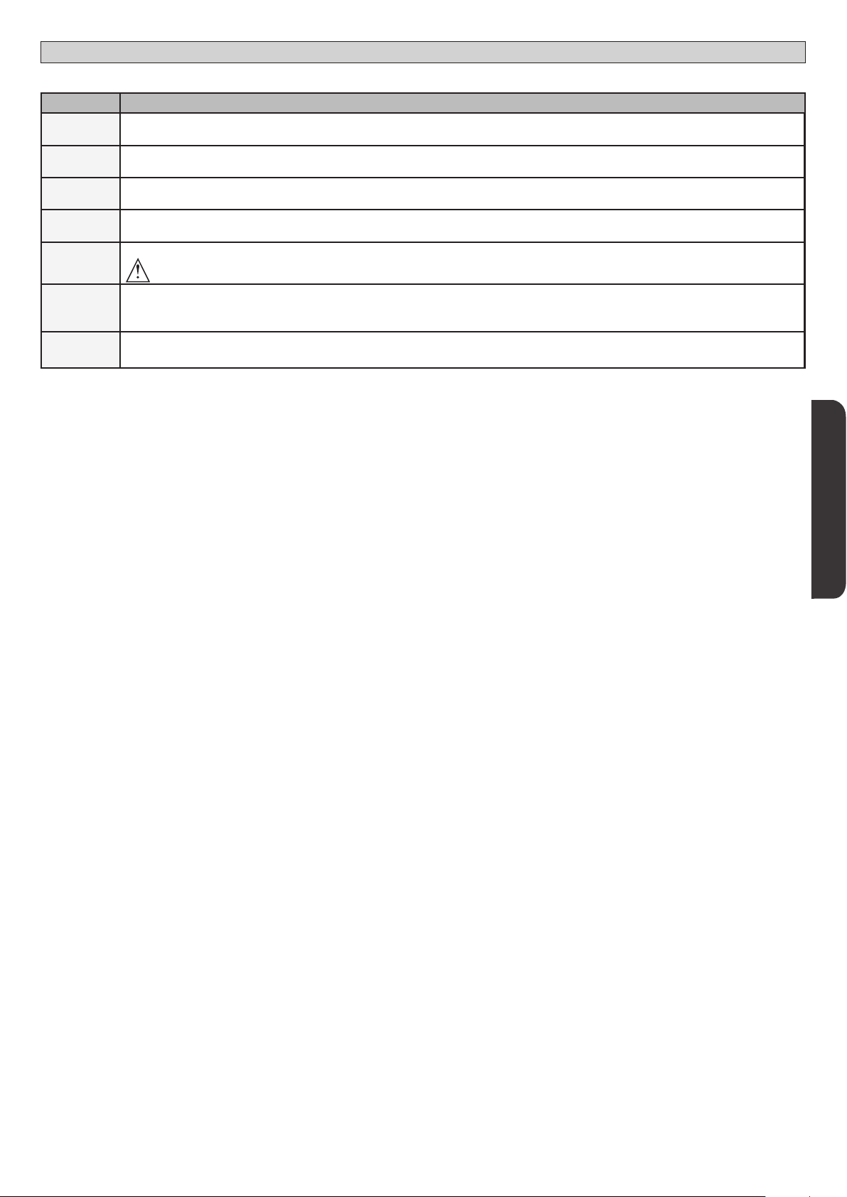
TABLEAU “C” MENU RADIO RADIO
Logique Description
D812865 00100_04
adj 1ch
adj 2ch
adj 3ch
adj 4ch
effacer 64
effacer 1
cod rk
Ajouter Touche 1ch
associe la touche voulue à la commande 1° canal radio
Ajouter Touche 2ch
associe la touche voulue à la commande 2° canal radio
Ajouter Touche 3ch
associe la touche voulue à la commande 3° canal radio
Ajouter Touche 4ch
associe la touche voulue à la commande 4° canal radio
Supprimer Liste
ATTENTION! Supprime complètement de la mémoire du récepteur toutes les radiocommandes mémorisées.
Elimine une radiocommande.
Retire une radiocommande (si clone ou replay est désactivée). Pour sélectionner la radiocommande à supprimer, écrivez la position ou appuyez
sur la touche de la radiocommande à supprimer (la position est achée).
Lecture code récepteur
Ache le code récepteur nécessaire pour cloner les radiocommandes.
MANUEL D’INSTALLATION
FRANÇAIS
RIGEL 6 - 61
Page 62

x2
MENÜZUGRIFF Fig. 1
[00-23]
Stellt die
Stunde ein
Einstellung Uhr
TAG
[00:59]
Stellt die
Minuten ein
sonntag 01 10-0 12-0chrono
02 00-0 00-0
01 07-0 12-0
02 14-0 18-0
montag
01 07-0 12-0
02 14-0 18-0
freitag
dienstag
.... .... ....
.... .... ....
mittwoch
.... .... ....
donnerstag
.... .... ....
samstag
sonntag
dienstag
mittwoch
donnerstag
freitag
samstag
00 00hh-MM
ZEITRAUM
BEGINN ENDE
[00:00 - 24:00] [00:00 - 24:00]
montag
***
0---
HALT Handbuch befolgen
10--
MENÜZUGRIFF Fig. 1
MONTAGEANLEITUNG
150- 1520 ok
Siehe MENÜ PARAMETER
Siehe MENÜ LOGIKEN
*** Passwordeingabe
Anforderung mit
Schutzniveaulogik eingestellt auf 1, 2, 3 oder 4
Legende:
Aufwärts
Abwärts
Bestätigung/
Aufleuchten Display
Zurück zum Hauptmenü
D812865 00100_04
LANG
autoset
stat
password
zufueg 1ch
zufueg 2ch
zufueg 3ch
zufueg 4ch
loeschen 64
loeschen 1
Für das Menü AUTOSET
siehe vereinfachtes Menü
Software-Versione Steuerung
vers
+
Gesamtzahl Betriebsvorgänge (x 100)
n.vorg
+
Zahl gespeicherte Fernsteuerungen
n.hs
+
Verzeichnis der letzten 30Fehler
err
0---
verst. taste
verst. taste
verst. taste
verst. taste
( 0001 )
OK
bft . . .
+/-
OK
0000
+/-
OK
00
+/-
OK
01.33
02.01
........
30.15
+ -
loslassen
loslassen
loslassen
gevue. taste
gevue. taste
gevue. taste
loslassen
o
o
dis
Code
diagnose
STRE
STRI
OPEN
CLS
PED
TIME
STOP
PHOT
PHOP
PHCL
BAR
baro
barc
SWC1
SWO1
SWC2
SWO2
ER01
ER02
ER03
ER04
er06
ER07
ER08
ER1x*
ER3x*
ER7x*
ERf3
ERF9
gevue. taste
Wenn gelöscht
Wenn nicht vorhanden
Wird deaktiviert, wenn Clone
externe Aktivierung Eingang Start START E
interne Aktivierung Eingang Start START I
Aktivierung Eingang OPEN
Aktivierung Eingang CLOSE
Aktivierung Eingang Fußgänger PED
Aktivierung Eingang TIMER oder Aktivierung programmierter
Zeitraum
Aktivierung Eingang STOP
Aktivierung des Eingangs Fotozelle PHOT oder bei Kongurierung als
überprüfte Fotozelle Aktivierung des zugeordneten Eingangs FAULT
Aktivierung des Eingangs Fotozelle in Önung PHOT OP oder bei
Kongurierung als überprüfte Fotozelle nur aktiv bei Önung
Aktivierung des zugeordneten Eingangs FAULT
Aktivierung des Eingangs Fotozelle in Schließung PHOT CL
oder bei Kongurierung als überprüfte Fotozelle nur aktiv bei
Schließung Aktivierung des zugeordneten Eingangs FAULT
Aktivierung des Eingangs Leiste BAR oder bei Kongurierung als
überprüfte Tastleiste Aktivierung des zugeordneten Eingangs FAULT
Aktivierung des Eingangs Leiste BAR mit Inversion NUR AKTIV BEI
ÖFFNUNG oder wenn konguriert als überprüfte Tastleiste aktiv
nur bei Önung, Aktivierung des zugeordneten Eingang FAULT
Aktivierung des Eingangs Leiste BAR mit Inversion NUR AKTIV BEI
SCHLIESSUNG oder wenn konguriert als überprüfte Tastleiste aktiv
nur bei Schließung, Aktivierung des zugeordneten Eingang FAULT
Aktivierung Eingang Endschalter Schließung des Motors 1 SWC1
Aktivierung Eingang Endschalter Önung des Motors 1 SWO1
Aktivierung Eingang Endschalter Schließung des Motors 2 SWC2
Aktivierung Eingang Endschalter Önung des Motors 2 SWO2
Test Fotozellen fehlgeschlagen Überprüfung Anschluss Fotozellen und/oder Einstellungen Logiken
Test Leiste fehlgeschlagen Überprüfung Anschluss Leisten und/oder Einstellungen Logiken
Test Fotozellen Önung fehlgeschlagen
Test Fotozellen Schließung fehlgeschlagen
Test Leiste 8k2 fehlgeschlagen
Test Leiste Önung fehlgeschlagen
Test Leiste Schließung fehlgeschlagen
Fehler Test Hardware Karte
Umkehrung wegen Hindernis - Amperostop Auf Hindernisse auf dem Weg überprüfen
Interner Fehler der Systemüberwachung.
Fehler in der Einstellung der Eingänge SAFE Die korrekte Einstellung der Eingänge SAFE kontrollieren
Überlastung am Ausgang des Elektroschlosses
*X= 0, 1, .., 9, A, B, C, D, E, F
10--
150- 1520 prg
Siehe MENÜ FUNK
BESCHREIBUNG ANMERKUNGEN
Überprüfung Anschluss Fotozellen und/oder Einstellung
Parameter/Logiken
Überprüfung Anschluss Fotozellen und/oder Einstellung
Parameter/Logiken
Den Anschluss der Leisten und/oder die Einstellung der
Parameter/Logiken überprüfen
Den Anschluss der Leisten und/oder die Einstellung der
Parameter/Logiken überprüfen
Den Anschluss der Leisten und/oder die Einstellung der
Parameter/Logiken überprüfen
- Die Anschlüsse des Motors überprüfen
- Hardwareprobleme der Karte (an den Kundendienst wenden)
Versuchen Sie, die Karte auszuschalten und dann wieder
einzuschalten. Benachrichtigen Sie den Kundendienst, falls
das Problem fortbesteht.
- Überprüfen Sie die Anschlüsse des Schlosses
- Ungeeignetes Schloss
62 - RIGEL 6
Page 63
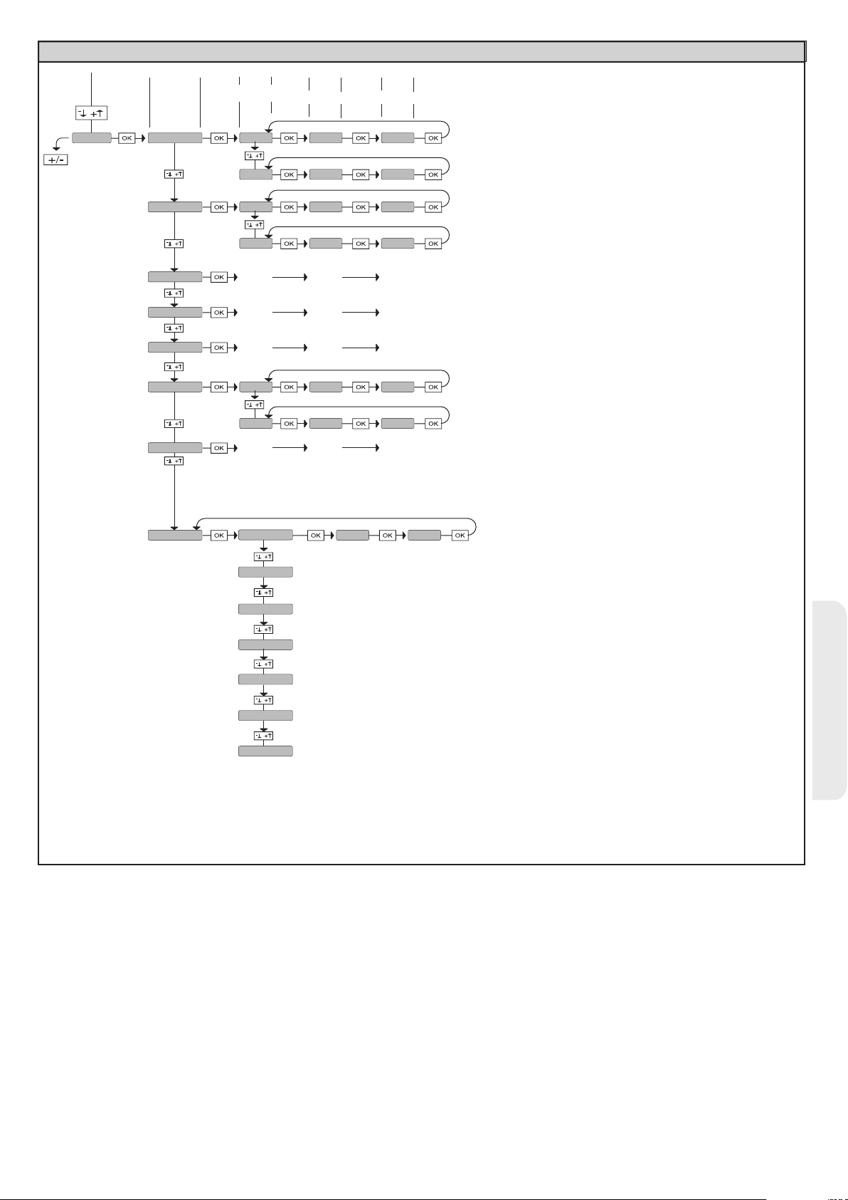
MONTAGEANLEITUNG
MENÜZUGRIFF Fig. 1
D812865 00100_04
TAG
sonntag 01 10-0 12-0chrono
montag
dienstag
mittwoch
donnerstag
freitag
samstag
ZEITRAUM
02 00-0 00-0
01 07-0 12-0
02 14-0 18-0
.... .... ....
.... .... ....
.... .... ....
01 07-0 12-0
02 14-0 18-0
.... .... ....
BEGINN ENDE
[00:00 - 24:00] [00:00 - 24:00]
sonntag
montag
dienstag
mittwoch
donnerstag
freitag
samstag
00 00hh-MM
[00-23]
Stellt die
Stunde ein
[00:59]
Stellt die
Minuten ein
Einstellung Uhr
DEUTSCH
RIGEL 6 - 63
Page 64

MONTAGEANLEITUNG
2) ALLGEMEINES
Die Steuerungstafel RIGEL 6 wird vom Hersteller mit der Standardeinstellung
geliefert. Dank dieser Änderung können die mit der Display-Programmiereinheit
oder der tragbaren Universal-Programmiereinheit eingestellte Parameter geändert
werden.
Die Steuerung unterstützt vollständig das Protokoll EELINK.
Die Haupteigenschaften sind:
- Steuerung von 1 oder 2 einphasigen Motoren mit Übertemperaturschutz
- Steuerung von 1 oder 2 einphasigen Motoren
Anmerkung: Es müssen zwei Motoren vom gleichen Typ verwendet werden.
- Elektronische Einstellung des Drehmoments
- Eingänge Kontrolle Endschalter Schließung/Önung, separat für beide Motoren
- separate Eingänge für die Sicherheitsvorrichtungen
- Verwaltung Zeiträume
- Integrierte Hinderniserfassung
- Vorheizung Motoren mit Ablesung des integrierten Fühlers
- Einstellbare elektrodynamische Bremsung
- Verlangsamung der Annäherungsgeschwindigkeit
- Integrierter Funkempfänger Rolling-Code mit Sender-Clonung.
Die Karte weist zur Vereinfachung der Wartungs- und Ersetzungsarbeiten eine
abnehmbare Klemmleiste auf. Wird zur Vereinfachung der Arbeit des Monteurs
mit einer Reihe von vorverkabelten Jumpern geliefert.
Die Jumper betreen die folgenden Klemmen: 41-42, 41-43, 41-44, 41-45, 7071, 70-72, 70-74, 76-77, 76-79, 81-82, 81-84. Entfernen Sie die entsprechenden
Jumper, falls die vorgenannten Klemmen benutzt werden.
ÜBERPRÜFUNG
Die Tafel RIGEL 6 kontrolliert (überprüft) die Betriebsrelais und die
Sicherheitsvorrichtungen (Fotozellen und Leisten) vor allen Önungs- und
Schließungszyklen.
Überprüfen Sie bei Funktionsstörungen den ordnungsgemäßen Betrieb der
angeschlossenen Geräte und die Verkabelungen.
ACHTUNG: Wenn der Torügel in einem öentlichen Bereich installiert ist oder
wenn wenn er mit automatischer Betriebsweise eingesetzt wird, empfehlen wir
die Installation eines Paars Fotozelle in einer Höhe von 5 cm sowie eines Paars
in einer Höhe von 40-50 cm. Unter automatischer Betriebsweise werden alle
Steuerungen verstanden, die nicht absichtlich vom Benutzer aktiviert werden
(Beispiel: Funktion TCA, Chrono usw.)
3) TECHNISCHE DATEN
Stromversorgung
Isolierung Netz/
Niederspannung
220-230V 50/60Hz(*)
> 2MOhm 500V
Dielektrische Starrheit Netz/Niederspannung 3750V~ für eine Minute
Stromversorgung
Zubehör
24V~ (max. Aufnahme 1A)
24V~safe
AUX 0
AUX 1
AUX 2
AUX 3
LOCK
Ausgerichteter Kontakt
220-230V N.O. (
Ausgerichteter Kontakt
220-230V N.O. (
Kontakt N.O. (MAX 220-230V~ 80W)
80W MAX)
80W MAX)
AUX0+
AUX1+
AUX2=
80W MAX
Kontakt N.O. (Max 24V~) 10W MAX
Ausgang für elektrische Verriegelung
12 V
10W MAX
Sicherungen siehe Fig. B
Anzahl Kombinationen:
Max. Anzahl der abspeicherbaren
Funksteuerungen:
4 Milliarden
63
(* weitere Spannungen auf Anfrage lieferbar)
Nutzungszyklus kontinuierlich kontinuierlich 1 Min. ON/
Betriebstemperatur -20°C/+50°C -20°C/+55°C -20°C/+50°C -20°C/+55°C
Max. Leistung
Motoren 220-230V
Max. Leistung
Motoren110-120V
2x375 W
1x750 W
2x320 W
1x390 W
2x250 W
1x500 W
2 Min. OFF
2x650 W
1x750 W
1 Min. ON/
2 Min. OFF
2x500 W
1x750 W
M1+M2+AUX0+AUX1+AUX2+AUX3+LOCK= 1300W MAX T=+50°C
Verwendbare Sendertypen:
Alle kompatiblen Sender mit ROLLING CODE
4) VORBEREITUNG LEITUNGEN Fig. A
5) ANSCHLÜSSE KLEMMLEISTE Fig. B
HINWEISE - Bitte beachten Sie bei den Verkabelungs- und Installationsarbeiten
die geltenden Bestimmungen sowie die Regeln der guten Technik.
Die Leiter, die mit unterschiedlichen Spannungen gespeist werden, müssen
physisch voneinander getrennt oder mit zusätzlichen Isolierungen von zumindest
1 mm isoliert werden. Die Leiter müssen in der Nähe der Klemmen an einer
zusätzlichen Befestigung verankert werden, zum Beispiel mit Kabelbindern. Alle
Verbindungskabel müssen vom Dissipator ferngehalten werden.
D812865 00100_04
sorgung
Stromver-
Motor
Aux
Anschlag
Klemme Denition Beschreibung
L PHASE
Einphasige Speisung 220-230V~ ±10%, 50 – 60HzN NULLLEITER
GND ERDE
10 MOT1 BETRIEB
Anschluss Motor 1. Verzögerung bei Schließung.11 MOT 1 COM
12 MOT1 BETRIEB
14 MOT1 BETRIEB
15 MOT 1 COM
16 MOT1 BETRIEB
20
21
22
23
24
25
26
27
28
29
40 Nicht verwendet
41 + REF SWE Gemein Endschalter
42 SWC 1 Endschalter Schließung des Motors 1 SWO1 (N.C.).
43 SWO 1 Endschalter Önung des Motors 1 SWO1 (N.C.).
44 SWC 2 Endschalter Schließung des Motors 2 SWC2 (N.C.).
45 SWO 2 Endschalter Önung des Motors 2 SWO2 (N.C.).
AUX 0 - KONTAKT, GESPEIST MIT
220-230V~
AUX 1 - KONTAKT, GESPEIST MIT
220-230V~
AUX 2 - FREIER KONTAKT (N.O.)
AUX 3 - FREIER KONTAKT (N.O.)
LOCK 12V
Anschluss Motor 2. Verzögerung bei Önung.
Anmerkung: Wenn “1 flugel”=1 kein Kabel an die Klemmen 14-15-16 anschließen
Kongurierbarer Ausgang AUX 0 - Default BLINKLEUCHTE.
MONOSTABILER FUNKKANAL/ KONTROLLLEUCHTE TOR OFFEN SCA / Steuerung NOTBELEUCHTUNG / Steuerung
ZONENBELEUCHTUNG / TREPPENBELEUCHTUNG / ALARM TOR OFFEN / BLINKLEUCHTE / ELKTROSCHLOSS
MIT AUSLÖSER / ELEKTROSCHLOSS MIT MAGNET / WARTUNG / BLINKLEUCHTE UND WARTUNG/ STATUS TOR /
BISTABILER FUNKKANAL / TIMERGESTEUERTER FUNKKANAL.
Bitte nehmen Sie auf die Tabelle “Kongurierung der AUX-Ausgänge Bezug”.
Kongurierbarer Ausgang AUX 1 - Default Ausgang ZONENBELEUCHTUNG.
MONOSTABILER FUNKKANAL/ KONTROLLLEUCHTE TOR OFFEN SCA / Steuerung NOTBELEUCHTUNG / Steuerung
ZONENBELEUCHTUNG / TREPPENBELEUCHTUNG / ALARM TOR OFFEN / BLINKLEUCHTE / ELKTROSCHLOSS
MIT AUSLÖSER / ELEKTROSCHLOSS MIT MAGNET / WARTUNG / BLINKLEUCHTE UND WARTUNG/ STATUS TOR /
BISTABILER FUNKKANAL / TIMERGESTEUERTER FUNKKANAL.
Bitte nehmen Sie auf die Tabelle “Kongurierung der AUX-Ausgänge Bezug”.
Kongurierbarer Ausgang AUX 2 - Default Ausgang KONTROLLLEUCHTE TOR OFFEN SCA.
MONOSTABILER FUNKKANAL/ KONTROLLLEUCHTE TOR OFFEN SCA / Steuerung NOTBELEUCHTUNG / Steuerung
ZONENBELEUCHTUNG / TREPPENBELEUCHTUNG / ALARM TOR OFFEN / BLINKLEUCHTE / ELKTROSCHLOSS
MIT AUSLÖSER / ELEKTROSCHLOSS MIT MAGNET / WARTUNG / BLINKLEUCHTE UND WARTUNG/ STATUS TOR /
BISTABILER FUNKKANAL / TIMERGESTEUERTER FUNKKANAL.
Bitte nehmen Sie auf die Tabelle “Kongurierung der AUX-Ausgänge Bezug”.
Kongurierbarer Ausgang AUX 3 - Default AUsgang 2. FUNKKANAL.
MONOSTABILER FUNKKANAL/ KONTROLLLEUCHTE TOR OFFEN SCA / Steuerung NOTBELEUCHTUNG / Steuerung
ZONENBELEUCHTUNG / TREPPENBELEUCHTUNG / ALARM TOR OFFEN / BLINKLEUCHTE / ELKTROSCHLOSS
MIT AUSLÖSER / ELEKTROSCHLOSS MIT MAGNET / WARTUNG / BLINKLEUCHTE UND WARTUNG/ STATUS TOR /
BISTABILER FUNKKANAL / TIMERGESTEUERTER FUNKKANAL.
Bitte nehmen Sie auf die Tabelle “Kongurierung der AUX-Ausgänge Bezug”.
Logik Typ Schloss = 0 - Ausgang Elektroschloss mit Auslöser 12V
Ausgang aktiviert mit einem Impuls bei jeder Önung und Schließung
Logik Typ Schloss= 1 - Ausgang Elektroschloss mit Magnet 12V .
Ausgang aktiviert bei Tor geschlossen und in Schließung
(MODELL ECB)
64 - RIGEL 6
Page 65

D812865 00100_04
Zubehör
Stromversorgung
Bedienelemente
Sicherheitsvorrichtungen
Antenne
NTC
MONTAGEANLEITUNG
Klemme Denition Beschreibung
50 24V-
Ausgang Stromversorgung Zubehör.
51 24V+
52 24 Vsafe+
60 Gemein Gemeine Eingänge IC 1 und IC 2
61 IC 1
62 IC 2
63 Gemein Gemeine Eingänge IC 3 und IC 4
64 IC 3
65 IC 4
70 Gemein Gemeine Eingänge STOP, SAFE 1 und SAFE 2
71 STOP
72 SAFE 1
73 FAULT 1 Eingang Überprüfung an SAFE 1 angeschlossenen Sicherheitsvorrichtungen.
74 SAFE 2
75 FAULT 2 Eingang Überprüfung an SAFE 2 angeschlossenen Sicherheitsvorrichtungen.
76 Gemein Gemeine Eingänge SAFE 3 und SAFE 4
77 SAFE 3
78 FAULT 3 Eingang Überprüfung an SAFE 3 angeschlossenen Sicherheitsvorrichtungen.
79 SAFE 4
80 FAULT 4 Eingang Überprüfung an SAFE 4 angeschlossenen Sicherheitsvorrichtungen.
81 Gemein Gemeine Eingänge SAFE 5 und SAFE 6
82 SAFE 5
83 FAULT 5 Eingang Überprüfung an SAFE 5 angeschlossenen Sicherheitsvorrichtungen.
84 SAFE 6
85 FAULT 6 Eingang Überprüfung an SAFE 6 angeschlossenen Sicherheitsvorrichtungen.
Y ANTENNE
# SHIELD
NTC Eingang für den Anschluss des Temperaturfühlers
Ausgang Stromversorgung für überprüfte Sicherheitsvorrichtungen (Sender Fotozellen und Sender Tastleiste).
Ausgang nur aktiv während des Manöverzyklusses.
Kongurierbarer Steuereingang 1 (N.O.) - Default START E.
START E / START I / OPEN / CLOSE / PED / TIMER / TIMER PED
Bitte nehmen Sie auf die Tabelle “Kongurierung der Steuereingänge” Bezug.
Kongurierbarer Steuereingang 2 (N.O.) - Default PED.
START E / START I / OPEN / CLOSE / PED / TIMER / TIMER PED
Bitte nehmen Sie auf die Tabelle “Kongurierung der Steuereingänge” Bezug.
Kongurierbarer Steuereingang 3 (N.O.) - Default OPEN.
START E / START I / OPEN / CLOSE / PED / TIMER / TIMER PED
Bitte nehmen Sie auf die Tabelle “Kongurierung der Steuereingänge” Bezug.
Kongurierbarer Steuereingang 4 (N.O.) - Default CLOSE.
START E / START I / OPEN / CLOSE / PED / TIMER / TIMER PED
Bitte nehmen Sie auf die Tabelle “Kongurierung der Steuereingänge” Bezug.
Der Befehl unterbricht das Manöver. (N.C.)
Falls nicht verwendet, überbrückt lassen.
Kongurierbarer Sicherheitseingang 1 (N.C.) - Default PHOT.
PHOT / PHOT TEST / PHOT OP / PHOT OP TEST / PHOT CL / PHOT CL TEST / BAR / BAR TEST / BAR 8K2/ B
8K2 OP/ BAR CL / BAR CL TEST / BAR 8K2 CL
Bitte nehmen Sie auf die Tabelle “Kongurierung der Sicherheitseingänge” Bezug.
Kongurierbarer Sicherheitseingang 2 (N.C.) - Default BAR.
PHOT / PHOT TEST / PHOT OP / PHOT OP TEST / PHOT CL / PHOT CL TEST / BAR / BAR TEST / BAR 8K2/ B
8K2 OP/ BAR CL / BAR CL TEST / BAR 8K2 CL
Bitte nehmen Sie auf die Tabelle “Kongurierung der Sicherheitseingänge” Bezug.
Kongurierbarer Sicherheitseingang 3 (N.C.) - Default PHOT OP.
PHOT / PHOT TEST / PHOT OP / PHOT OP TEST / PHOT CL / PHOT CL TEST / BAR / BAR TEST / BAR OP / BAR OP TEST / BAR CL / BAR CL TEST /
Bitte nehmen Sie auf die Tabelle “Kongurierung der Sicherheitseingänge” Bezug.
Kongurierbarer Sicherheitseingang 4 (N.C.) - Default PHOT CL.
PHOT / PHOT TEST / PHOT OP / PHOT OP TEST / PHOT CL / PHOT CL TEST / BAR / BAR TEST / BAR OP / BAR OP TEST / BAR CL / BAR CL TEST /
Bitte nehmen Sie auf die Tabelle “Kongurierung der Sicherheitseingänge” Bezug.
Kongurierbarer Sicherheitseingang 5 (N.C.) - Default PHOT.
PHOT / PHOT TEST / PHOT OP / PHOT OP TEST / PHOT CL / PHOT CL TEST / BAR / BAR TEST / BAR OP / BAR OP TEST / BAR CL / BAR CL TEST /
Bitte nehmen Sie auf die Tabelle “Kongurierung der Sicherheitseingänge” Bezug.
Kongurierbarer Sicherheitseingang 6 (N.C.) - Default BAR.
PHOT / PHOT TEST / PHOT OP / PHOT OP TEST / PHOT CL / PHOT CL TEST / BAR / BAR TEST / BAR OP / BAR OP TEST / BAR CL / BAR CL TEST /
Bitte nehmen Sie auf die Tabelle “Kongurierung der Sicherheitseingänge” Bezug.
Eingang Antenne.
Verwenden Sie eine auf 433 MHz abgestimmte Antenne. Verwenden Sie die Verbindung Antenne-Empfänger ein Koaxialkabel
RG58. Das Vorhandensein von metallischen Massen in der Nähe der Antenne kann den Funkempfang stören. Montieren Sie
die Antenne bei ungenügender Reichweite des Senders an einer geeigneteren Stelle.
AR OP / BAR OP TEST / BAR
AR OP / BAR OP TEST / BAR
DEUTSCH
Kongurierung der AUX-Ausgänge
Logik Aux= 0 - Ausgang MONOSTABILER FUNKKANAL.
Der Kontakt bleibt bei der Aktivierung. Funkkanals 1s geschlossen.
Logik Aux= 1 - Ausgang KONTROLLLEUCHTE TOR OFFEN SCA.
Der Kontakt bleibt während der Önung und bei oenem Flügel geschlossen, intermittierend während der Schließung und oen bei geschlossenem Flügel.
Logik Aux= 2 - Ausgang Befehl NOTBELEUCHTUNG.
Der Kontakt bleibt nach dem letzten Manöver für 90 Sekunden geschlossen.
Logik Aux= 3 - Ausgang Befehl ZONENBELEUCHTUNG.
Der Kontakt bleibt für die gesamte Dauer des Manövers aktiv.
Logik Aux= 4 - Ausgang TREPPENBELEUCHTUNG.
Der Kontakt bleibt bei Beginn des Manövers für 1Sekunde geschlossen.
Logik Aux= 5 - Ausgang ALARM TOR OFFEN.
Der Kontakt bleibt geschlossen, falls der Torügel für eine Zeit oen bleibt, die das Doppelte der in TCA eingestellten Zeit beträgt.
Logik Aux= 6 - Ausgang BLINKLEUCHTE.
Der Kontakt während der Bewegung der Torügel geschlossen.
Logik Aux= 7 - Ausgang für EINRASTENDES ELEKTROSCHLOSS.
Der Kontakt bleibt bei jeder Önung und jeder Schließung 2 Sekunden geschlossen.
Logik Aux= 8 - Ausgang für MAGNET-ELEKTROSCHLOSS.
Der Kontakt bleibt geschlossen bei geschlossenem Tor und während des Schließungsmanövers.
Logik Aux= 9 – Ausgang WARTUNG.
Der Kontakt bleibt beim Erreichen des im Parameter Wartung eingestellten Werts geschlossen, um die Wartungsanforderung anzuzeigen.
Logik Aux= 10 – Ausgang BLINKLEUCHTE WARTUNG.
Der Kontakt während der Bewegung der Torügel geschlossen. Wenn der im Parameter Wartung eingestellte Wert bei Ende des Manövers bei geschlossenem Tor erreicht wird,
schließt sich der Kontakt 4 Mal für 10 Sekunden und önet sich dann für 5 Sekunden, um die Wartungsanforderung anzuzeigen.
Logik Aux= 11 – Nicht Verfügbar
RIGEL 6 - 65
Page 66

MONTAGEANLEITUNG
Kongurierung der AUX-Ausgänge
Logik Aux= 12 – Nicht Verfügbar
Logik AUX = 13 - Ausgang STATUS TOR.
Der Kontakt bleibt geschlossen, wenn das Tor geschlossen ist.
Logik AUX= 14 - Ausgang BISTABILER FUNKKANAL
Der Kontakt ändert den Status (oen/geschlossen) bei Aktivierung des Funkkanals
Logik AUX= 15 - Ausgang TIMERGESTEUERTER FUNKKANAL
Der Kontakt bleibt bei Aktivierung des Funkkanals für eine programmierbare Zeit geschlossen (Zeit Ausgang)
Falls die Taste während dieser Zeit erneut gedrückt wird, beginnt die Zählung der Zeit erneut.
Kongurierung der Steuereingänge
Logik IC= 0 - Als Start E kongurierter Eingang. Funktionsweise gemäß Logik MOV. SCHRITT SCHRITT. Externer Start für Ampelsteuerung.
Logik IC= 1 - Als Start I kongurierter Eingang. Funktionsweise gemäß Logik MOV. SCHRITT SCHRITT. Interner Start für Ampelsteuerung.
Logik IC= 2 - Als Open kongurierter Eingang.
Der Befehl führt eine Önung aus. Wenn der Eingang geschlossen bleibt, bleiben die Flügel bis zur Önung des Kontakts oen. Bei oenem Kontakt schließt die Automatisierung
nach der Zeit TCA, falls aktiv.
Logik IC= 3 - Als Close kongurierter Eingang.
Der Befehl führt die Schließung aus.
Logik IC= 4 - Als Ped kongurierter Eingang.
Der Befehl führt eine partielle Fußgängerönung aus. Funktionsweise gemäß Logik MOV. SCHRITT SCHRITT
Logik IC= 5 - Als Timer kongurierter Eingang.
Funktionsweise wie bei Open, aber die Schließung ist auch nach einem Stromausfall garantiert.
Logik IC= 6 - Als Timer Ped kongurierter Eingang.
Der Befehl führt eine partielle Fußgängerönung aus. Wenn der Eingang geschlossen bleibt, bleibt der Flügel bis zur Önung des Kontakts oen. Wenn der Eingang geschlossen
bleibt und ein Befehl Start E, Start I oder Open aktiviert wird, wird ein vollständiges Manöver ausgeführt, um dann die Fußgängerönung wiederherzustellen. Die Schließung wird
auch nach einem Stromausfall garantiert.
Kongurierung der Sicherheitseingänge
Logik SAFE= 0 - Als Phot kongurierter Eingang, Fotozelle nicht überprüften (*). (Fig. F, Pos. 1).
Gestattet das Anschließen von Vorrichtungen ohne zusätzlichen Kontakt für die Überprüfung. Bei Abdunklung sind die Fotozellen sowohl beim Önen, als auch beim Schließen aktiv.
Eine Abdunklung der Fotozelle beim Schließen schaltet die Bewegungsrichtung erst nach der Freigabe der Fotozelle um. Falls nicht verwendet, überbrückt lassen.
Logik SAFE= 1 - Als Phot test kongurierter Eingang, überprüfte Fotozelle. (Fig. F, Pos. 2).
Aktiviert die Überprüfung der Fotozellen bei Beginn des Manövers. Bei Abdunklung sind die Fotozellen sowohl beim Önen, als auch beim Schließen aktiv. Eine Abdunkelung der
Fotozelle beim Schließen schaltet die Bewegungsrichtung erst nach der Freigabe der Fotozelle um.
Logik SAFE= 2 - Als Phot op kongurierter Eingang, Fotozelle aktiv nur bei Önung nicht überprüften (*). (Fig. F, Pos. 1)
Gestattet das Anschließen von Vorrichtungen ohne zusätzlichen Kontakt für die Überprüfung. Deaktiviert beim Schließen das Funktionieren der Fotozelle bei Abdunkelung. Blockiert
in der Phase der Önung die Bewegung für die Dauer der Abdunkelung der Fotozelle. Falls nicht verwendet, überbrückt lassen.
Logik SAFE= 3 - Als Phot op test kongurierter Eingang, überprüfte Fotozelle aktiv nur bei Önung (Fig. F, Pos. 2).
Aktiviert die Überprüfung der Fotozellen bei Beginn des Manövers. Deaktiviert beim Schließen das Funktionieren der Fotozelle bei Abdunkelung. Blockiert in der Phase der Önung
die Bewegung für die Dauer der Abdunkelung der Fotozelle.
Logik SAFE= 4 - Als Phot cl kongurierter Eingang, Fotozelle aktiv nur bei Schließung nicht überprüften (*). (Fig. F, Pos. 1)
Gestattet das Anschließen von Vorrichtungen ohne zusätzlichen Kontakt für die Überprüfung. Deaktiviert beim Önen das Funktionieren der Fotozelle bei Abdunkelung. Beim
Schließen schaltet sie direkt um. Falls nicht verwendet, überbrückt lassen.
Logik SAFE= 5 - Als Phot cl test kongurierter Eingang, überprüfte Fotozelle aktiv nur bei Schließung (Fig. F, Pos. 2).
Aktiviert die Überprüfung der Fotozellen bei Beginn des Manövers. Deaktiviert beim Önen das Funktionieren der Fotozelle bei Abdunkelung. Beim Schließen schaltet sie direkt um.
Logik SAFE= 6 - Als Bar kongurierter Eingang, Tastleiste nicht überprüften (*). (Fig. F, Pos. 3)
Gestattet das Anschließen von Vorrichtungen ohne zusätzlichen Kontakt für die Überprüfung. Der befehl kehrt die Bewegung für 2Sek . um. Falls nicht benutzt den Jumper eingesetzt lassen
Logik SAFE= 7 - Als Bar kongurierter Eingang, überprüfte Tastleiste (Fig. F, Pos. 4).
Aktiviert die Überprüfung der Tastleisten bei Beginn des Manövers. Der Befehl kehrt die Bewegung für zwei Sekunden um.
Logik SAFE= 8 - Als Bar 8k2 kongurierter Eingang (Fig. F, Pos. 5). Eingang für Widerstandskante 8K2.
Der Befehl kehrt die Bewegung für zwei Sekunden um.
Logik SAFE=9 Eingang konguriert als Bar op, Tastleiste mit Inversion nur aktiv bei Önung, bewirkt bei Aktivierung während der Schließung das Anhalten der Automatisierung (STOP)
(Fig.F, Rif. 3).
Gestattet das Anschließen von Vorrichtungen ohne zusätzlichen Kontakt für die Überprüfung. Der Eingri in der Phase der Önung kehr t die Bewegung für 2 Sek. Um, der Eingri in der
Phase Schließung bewirkt das Anhalten. Falls nicht verwendet, überbrückt lassen.
Logik SAFE=10 Eingang konguriert als Bar op test, überprüfte Tastleiste mit Inversion nur aktiv bei Önung, bewirkt bei Aktivierung während der Schließung das Anhalten der Automatisierung (STOP) (Fig.F, Rif. 4).
Aktiviert die Überprüfung der Tastleisten bei Beginn des Manövers. Der Eingri in der Phase der Önung kehrt die Bewegung für 2 Sek . um, der Eingri in der Phase Schließung bewirkt das Anhalten.
Logik SAFE=11 Eingang konguriert als Bar 8k2 op, Leiste 8k2 mit Inversion nur aktiv bei Önung, bewirkt bei Aktivierung während der Schließung das Anhalten der Automatisierung
(STOP) (Fig.F, Rif. 5).
Der Eingri in der Phase der Önung kehrt die Bewegung für 2 Sek. um, der Eingri in der Phase Schließung bewirkt das Anhalten.
Logik SAFE=12 Eingang konguriert als Bar cl, Tastleiste mit Inversion nur aktiv bei Schließung, bewirkt bei Aktivierung während der Önung das Anhalten der Automatisierung (STOP) (Fig.F, Rif. 3).
Gestattet das Anschließen von Vorrichtungen ohne zusätzlichen Kontakt für die Überprüfung. Der Eingri in der Phase der Schließung kehrt die Bewegung für 2 Sek. Um, der Eingri in
der Phase Önung bewirkt das Anhalten. Falls nicht verwendet, überbrückt lassen.
Logik SAFE=13 Eingang konguriert als Bar cl test, überprüfte Tastleiste mit Inversion nur aktiv bei Schließung, bewirkt bei Aktivierung während der Önung das Anhalten der Automatisierung (STOP) (Fig.F, Rif. 4).
Aktiviert die Überprüfung der Tastleisten bei Beginn des Manövers. Der Eingri in der Phase der Schließung kehrt die Bewegung für 2 Sek. Um, der Eingri in der Phase Ö nung bewirkt das Anhalten.
Logik SAFE=14 Eingang konguriert als Bar 8k2 cl, Leiste 8k2 mit Inversion nur aktiv bei Schließung, bewirkt bei Aktivierung während der Önung das Anhalten der Automatisierung (STOP) (Fig.F, Rif. 5).
Der Eingri in der Phase der Schließung kehrt die Bewegung für 2 Sek. Um, der Eingri in der Phase Önung bewirkt das Anhalten.
(*) Bei Installation von Vorrichtungen vom Typ “D” (wie deniert von EN12453) mit nicht überprüftem Anschluss wird eine obbligatorische Wartung mit
zumindest halbjährlicher Frequenz vorgeschrieben.
D812865 00100_04
66 - RIGEL 6
Page 67
MONTAGEANLEITUNG
6) SICHERHEITSVORRICHTUNGEN
Anmerkung: Nur empfangende Sicherheitsvorrichtungen mit freiem
Austauschkontakt verwenden.
D812865 00100_04
6.1) ÜBERPRÜFTE GERÄTE Fig. E
6.2) ANSCHLUSS VON EINEM PAAR NICHT ÜBERPRÜFTEN FOTOZELLEN . Fig.C
7 ZUGANG ZU DEN MENÜS: FIG. 1
7.1) MENÜ PARAMETER PARA
7.2) MENÜ LOGIKEN LOGIC TABELLE “B” LOGIKEN
7.3) MENÜ FUNK radio TABELLE “C” FUNK
- WICHTIGER HINWEIS: KENNZEICHNEN SIE DEN ERSTEN ABGESPEICHERTEN
SENDER MIT DER SCHLÜSSEL-MARKE (MASTER).
Bei der manuellen Programmierung vergibt der erste Sender den SCHLÜSSELCODE
DES EMPFÄNGERS; dieser Code ist für das anschließende Clonen der
Funkbedienungen erforderlich.
Der eingebaute Empfänger Clonix weist außerdem einige wichtige erweiterte
Funktionen auf:
• ClonendesMaster-Senders(Rolling-CodeoderfesterCode)
• ClonenzurErsetzungvonbereitsindenEmpfängereingegebenenSendern
• VerwaltungderDatenbankderSender
• VerwaltungEmpfängergruppe
Bitte nehmen Sie für die Benutzung dieser erweiterten Funktionen auf die
Anleitung des Universal-Programmiergeräts und die allgemeine Anleitung für
die Programmierung der Empfänger Bezug.
Bei Benutzung einer 4-Kanal-Fernsteuerung empfehlen wir, einen Kanal für die
Funktion Anhalten (STOP) zu reservieren.
7.4 MENÜ DEFAULT default
Stellt die Steuereinheit auf die voreingestellten Defaultwerte zurück. Nach einer
Rückstellung muss ein neues AUTOSET vorgenommen werden.
7.5 MENÜ SPRACHE sprache
Gestattet die Einstellung der Displaysprache der Programmiereinheit.
7.6 MENÜ AUTOSET AUTOset
Autoset-Phasen für Motoren mit Endschalter (Fig. D1):
1 - Bringen Sie die Torügel an die Endschalter Schließung.
2 - Starten Sie eine Autoset-Operation im entsprechenden Menü und drücken
Sie die Taste OK, um das Önungsmanöver des Motors 1 zu starten.
3 - Auf dem Display wird die Meldung “M1.o” angezeigt.
4 - Warten Sie ab, bis der Endschalter Önung eingreift, um das Önungsma-
növer des Motors 1 zu beenden.
5 - Automatisch startet das Önungsmanöver des Motors 2. Auf Display “M2.o”.
6 - Warten Sie ab, bis der Endschalter Önung eingreift, um das Önungsma-
növer des Motors 2 zu beenden; auf dem Display wird die Meldung „CLOSE“
angezeigt.
7 - Drücken Sie die Taste OK, um das Schließungsmanöver des Motors 2 zu
starten. Auf Display “M2.c”.
8 - Warten Sie ab, bis der Endschalter Schließung eingreift, um das Schließungs-
manöver des Motors 2 zu beenden.
9 - Automatisch startet das Schließungsmanöver des Motors 1. Auf Display
“M1.c”.
10 - Warten Sie ab, bis der Endschalter Schließung eingreift, um das Schließungs-
manöver des Motors 1 zu beenden.
Falls die Arbeitszeit korrekt abgespeichert worden ist, wird auf dem Display
die Meldung “OPEN” angezeigt.
11 - Drücken Sie die Taste OK, um den zweiten Zyklus zu starten, um den Wer t des
Drehmoments zu berechnen, der für die Bewegung des Torügels bzw. der
Torügel erforderlich ist; auf dem Display wird die Meldung “M1.o” angezeigt.
12 - Warten Sie ab, bis der Endschalter Önung eingreift, um das Önungsma-
növer des Motors 1 zu beenden.
13 - Automatisch startet das Önungsmanöver des Motors 2. Au Display “M2.o”.
14 - Warten Sie ab, bis der Endschalter Önung eingreift, um das Önungsma-
növer des Motors 2 zu beenden; auf dem Display wird die Meldung „CLOSE“
angezeigt.
15 - Drücken Sie die Taste OK, um das Schließungsmanöver des Motors 2 zu
starten. Au Display “M2.c”.
16 - Warten Sie ab, bis der Endschalter Schließung eingreift, um das Schließungs-
manöver des Motors 2 zu beenden.
17 - Automatisch startet das Schließungsmanöver des Motors 1. Auf Display
“M1.c”.
18 - Warten Sie ab, bis der Endschalter Schließung eingreift, um das Schließungs-
manöver des Motors 1 zu beenden.
19 - Falls der Autoset korrekt abgeschlossen worden ist, wird auf dem Display die
Meldung “OK” angezeigt; falls der Autoset fehlschlägt, wird auf dem Display
die Meldung “KO” angezeigt und die Phase 1 wird wiederholt.
Falls ein aktiver Motor eingestellt ist, werden die Phasen für den Motor 2 nicht
ausgeführt.
Autoset-Phasen für Motoren ohne Endschalter (Fig. D2):
1 - Bringen Sie die Torügel an die Endschalter Schließung.
2 - Starten Sie eine Autoset-Operation im entsprechenden Menü und drücken
Sie die Taste OK, um das Önungsmanöver des Motors 1 zu starten.
3 - Auf dem Display wird die Meldung “M1.o” angezeigt.
4 - Drücken Sie die Taste OK, um das Önungsmanöver des Motors 1 zu beenden.
Auf Display “M2.o”
5 - Automatisch startet das Önungsmanöver des Motors 2.
6 - Drücken Sie die Taste OK, um das Önungsmanöver des Motors 2 zu beenden;
auf dem Display wird die Meldung „CLOSE“ angezeigt.
7 - Drücken Sie die Taste OK, um das Schließungsmanöver des Motors 2 zu
starten. Auf Display “M2.c”
8 - Drücken Sie die Taste OK, um das Schließungsmanöver des Motors 2 zu
beenden. Auf Display “M1.c”
9 - Automatisch startet das Schließungsmanöver des Motors 1.
10 - Drücken Sie die Taste OK, um das Schließungsmanöver des Motors 1 zu
beenden.
Falls die Arbeitszeit korrekt abgespeichert worden ist, wird auf dem Display
die Meldung “OPEN” angezeigt.
11 - Drücken Sie die Taste OK, um den zweiten Zyklus zu star ten, um den Wert des
Drehmoments zu berechnen, der für die Bewegung des Torügels bzw. der
Torügel erforderlich ist; auf dem Display wird die Meldung “M1.o” angezeigt.
12 - Warten Sie ab, bis die Arbeitszeit des Motor 1 eingreift, um das Önungsma-
növer des Motors 1 zu beenden.
13 - Automatisch startet das Önungsmanöver des Motors 2. Auf Display “M2.o”
14 - Warten Sie ab, bis die Arbeitszeit des Motors 2 eingreift, um das Önungsma-
növer des Motors 2 zu beenden; auf dem Display wird die Meldung „CLOSE“
TABELLE “A” PARAMETER
angezeigt.
15 - Drücken Sie die Taste OK, um das Schließungsmanöver des Motors 2 zu
starten. Auf Display “M2.c”
16 - Warten Sie ab, bis die Arbeitszeit des Motor 2 eingreift, um das Schließungs-
manöver des Motors 2 zu beenden.
17 - Automatisch startet das Schließungsmanöver des Motors 1. Auf Display
“M1.c”
18 - Warten Sie ab, bis die Arbeitszeit des Motor 1 eingreift, um das Schließungs-
manöver des Motors 1 zu beenden.
19 - Falls der Autoset korrekt abgeschlossen worden ist, wird auf dem Display die
Meldung “OK” angezeigt; falls der Autoset fehlschlägt, wird auf dem Display
die Meldung “KO” angezeigt und die Phase 1 wird wiederholt.
Falls ein aktiver Motor eingestellt ist, werden die Phasen für den Motor 2 nicht
ausgeführt.
Während dieser Phase müssen die Abdunklung der Fotozellen, der Eingri der
Sicherheitsvorrichtungen sowie die Benutzung der Befehle START, STOP und des
Displays verhindert werden.
Am Ende dieser Operation hat die Steuerungseinheit die optimalen Werte der
Parameter und die Arbeitszeiten automatisch eingestellt. Überprüfen Sie sie und
ändern Sie sie gegebenenfalls, wie im Abschnitt Programmierung beschrieben.
ACHTUNG!! Stellen Sie sicher, dass der Wert der Kraft, gemessen an
den gemäß Norm EN12445 vorgesehenen Punkten, kleiner als der in
der Norm EN 12453 angegeben ist.
Die Aufprallkräfte müssen unter Verwendung von aktiven Leisten
gemäß EN12978 begrenzt werden.
Achtung!! Während der Auto-Einstellung ist die Funktion
Hinderniserfassung nicht aktiv; der Monteur muss die Bewegung der
Automatisierung überwachen und verhindern, dass Personen oder
Sachen in den Bewegungsbereich der Automatisierung gelangen.
7.7) SEQUENZ ZUR ÜBERPRÜFUNG DER INSTALLATION
1. Die druck- oder stromempndlichen Schutzvorrichtungen (zum Beispiel aktive
Leiste) anbringen
2. Führen Sie das Verfahren AUTOSET aus (*).
3. Überprüfen Sie die Aufprallkräfte: gehen Sie zu Punkt 5 der Sequenz, falls sie
innerhalb der Grenzwerte liegen; anderenfalls
4. Die Bewegung des Triebs nur in der Modalität “Mann anwesend” überprüfen
5. Sicherstellen, dass alle Erfassungsvorrichtungen im Manöverbereich ordnungs-
gemäß funktionieren
(*) Stellen Sie vor der Ausführung von Autoset sicher, dass alle Montage- und
Sicherungsarbeiten ordnungsgemäß ausgeführt worden sind, wie vorgeschrieben
in den Anweisungen zur Installation im Handbuch der Motorisierung und, dass die
Parameter Kraft Önung/Schließung, Verlangsamung und Verlangsamungszeit
eingestellt worden sind.
7.8 MENÜ STATISTIKEN
Gestattet das Anzeigen der Version der Karte, der Gesamtzahl der Manöver (in
Hunderten), der Anzahl der abgespeicherten Funksteuerungen und der letzten
30 Fehler (die ersten beiden Ziern gegen die Position und die letzten beiden
den Fehlercode an). Der Fehler 01 ist der jüngste.
7.9) MENÜ PASSWORD
Gestattet die Eingabe eines Passwords für die Programmierung der Karte
über das Netz U-link”.
MIT DER LOGIK “SCHUTZNIVEAU” eingestellt auf 1, 2, 3 oder 4 wird der
Zugang zum Menü Programmierung angefordert. Nach 10 fehlgeschlagenen
Zugangsversuchen infolge muss vor einem erneuten Versuch drei Minuten
gewartet werden. Während dieses Zeitraums wird bei jedem Zugangsversuch
“BLOC” angezeigt. Das Default-Password ist 1234
7.10) MENÜ CHRONO Fig. I
Gestattet die Einstellung der Funktionsweise mit Zeiträumen.
Es können bis zu zwei Zeiträume pro Tag programmiert werden, in denen das
Tor oen bleibt (von Montag bis Sonntag)
Im Zeitraum wird eine Önung der Torügel vorgenommen, die bis zum Ende
des Zeitraums oen bleiben.
8) DRÜCKEN ANSCHLAG SCHLIESSUNG Fig. F Rif. A-B
RICHTUNG ÖFFNUNG Fig. F Rif. C-D
9) ANSCHLUSS AN ERWEITERUNGSKARTEN UND HANDPROGRAMMIEREINHEI
(Fig. G)
Bitte nehmen Sie auf das entsprechende Handbuch Bezug.
10) ZUSATZMODULE U-LINK
Bitte nehmen Sie auf die Anweisungen zu den Modulen U-link Bezug.
Die Benutzung einiger Module führt zu einer Verringerung der Funkreichweite. Passen Sie die Anlage durch verwendung einer geeigneten Antenne mit 433 MHz an.
11) WIDERHERSTELLUNG DER WERKSEINSTELLUNG (Fig. H)
ACHTUNG: Das Steuergerät wird auf die Werkseinstellung zurückgestellt
und alle abgespeicherten Fernbedienungen werden gelöscht.
ACHTUNG! Ein falsche Einstellung kann zur Verletzung von Personen oder
Tieren sowie zu Sachschäden führen.
- Unterbrechen Sie die Stromversorgung der Karte (Fig. H- Pos. 1)
- Önen Sie den Eingang Stop und drücken Sie gleichzeitig die Tasten - und OK
(Fig. H - Pos. 2)
- Stellen Sie die Stromversorgung der Karte wieder her (Fig. H - Pos. 3)
- Das Display zeigt RST an; bestätigen Sie innerhalb von drei sekunden durch
Drücken der Taste OK (Fig. H - Pos. 4)
- Warten Sie das Ende des Vorgangs ab (Fig. H - Pos. 5)
- Vorgang beendet (Fig. H - Pos. 6)
ACHTUNG! Eine falsche Einstellung kann zur Verletzung von Personen oder
Tierensowie zu Sachschäden führen.
ACHTUNG: Stellen Sie sicher, dass der Wert der Kraft, gemessen an
den gemäß Norm EN12445 vorgesehenen Punkten, kleiner als der in
der Norm EN 12453 angegeben ist.
Die Aufprallkräfte können durch die Verwendung von verformbaren
Leisten reduziert werden.
Wir empfehlen, zur Erzielung eines besseren Resultats den Autoset mit Motoren
in Ruhestellung vorzunehmen (das heißt nicht überhitzt von einer größeren
Anzahl von ausgeführten Manövern).
DEUTSCH
RIGEL 6 - 67
Page 68

TABELLE “A” MENÜ PARAMETER - (param)
MONTAGEANLEITUNG
Parameter Min. Max. Default Persönlich Denition Beschreibung
t. arbeit.
ot.1
t. arbeit.
ot.2
teil|ffnung
T VERZIGERN
AUF
T VERZIGERN
ZU
verlangsa ung
ot.1
verlangsa ung
ot.2
TCA
Z.RAUM.AMP
t.ausgang
CRAFT OFF
CRAFT SCHL
craft verl
bre se
notbre s
vorheiz.
3.0 180.0 60.0
3.0 180.0 60.0
3 90 6
0 10 3
0 25 3
0 30 0
0 30 0
0 120 10
1 180 40
1 240 10
1 99 50
1 99 50
1 99 50
0 99 0
0 99 60
0 99 30
Arbeitszeit für
motor 1[s]
Arbeitszeit für
motor 2[s]
Partielle Önung M1
[s]
Verzögerungszeit
Önung Motor 2 [s]
Verzögerungszeit
Schließung Motor 1 [s]
Verlangsamungsdauer
motor 1[s]
Verlangsamungsdauer
motor 2[s]
Zeit automatische
Schließung [s]
Räumungszeit
Ampelbereich [s]
Aktivierungszeit des
timergesteuerten
Ausgangs [s]
Kraft Flügel bei Önung
[%]
Kraft Flügel bei
Schließung [%]
Kraft der Motoren bei der
Verlangsamung
[%]
Bremsung
[%]
Notbremsung
[%]
Vorerwärmung
[%]
Stellt den Wert der Arbeitszeit in Sekunden für den Motor 1 / 2 ein
Am Ende eines Autosets wird der reale Arbeitswert des Motors eingestellt
Zeit der partiellen Önung nach Aktivierung des Befehls Fußgänger PED des Motors M1
Verzögerungszeit bei Önung des Motors 2 gegenüber dem Motor 1
Verzögerungszeit bei Schließung des Motors 1 gegenüber dem Motor 2
Stellt die Verlangsamungszeit der Annäherung ein. Die Verlangsamungszeit wird von
der Arbeitszeit abgezogen.
ANMERKUNG: Diese Funktion nur verwenden, wenn Endschalter vorhanden sind.
ANMERKUNG: Nicht verwenden mit hydraulischen Motoren.
(***)
Wartezeit vor der automatischen Schließung.
Räumungszeit des Bereiches mit dem von der Ampel geregelten Verkehr.
Dauer der Aktivierung des Ausgangs des timergesteuerten Funkkanals in Sekunden
Vom Flügel ausgeübte Kraft bei der Önung
Gibt den Prozentsatz der angewendeten Kraft an, bezogen auf den max. Wert.
ACHTUNG: Wirkt sich direkt in der Stoßkraft aus: sicherstellen, dass der
eingestellte Wert den geltenden Sicherheitsbestimmungen entspricht (*).
Quetschschutzsicherheitsvorrichtungen installieren (**).
(***)
Vom Flügel ausgeübte Kraft bei der Schließung.
Gibt den Prozentsatz der angewendeten Kraft an, bezogen auf den max. Wert.
ACHTUNG: Wirkt sich direkt in der Stoßkraft aus: sicherstellen, dass der
eingestellte Wert den geltenden Sicherheitsbestimmungen entspricht (*).
Quetschschutzsicherheitsvorrichtungen installieren (**).
(***)
Vom Flügel bzw. von den Flügeln bei der Verlangsamung ausgeübte Kraft.
Entspricht (in Prozent) der beim Verlangsamen aufgewandten Kraft.
ACHTUNG: Wirkt sich direkt in der Stoßkraft aus: sicherstellen, dass der
eingestellte Wert den geltenden Sicherheitsbestimmungen entspricht (*).
Quetschschutzsicherheitsvorrichtungen installieren (**).
(***)
Den Bremswert von 0 (min.) bis 99 % (max.) einstellen, der mit dem Gewicht des Tores
und den vorhandenen mechanischen Belastungen kompatibel ist.
Stellt den Wert der Notfallbremsung von 0 % (min.) bis 99 % (max.) ein, die vorgenommen wird, wenn die Sicherheitsbefehle aktiviert werden, die an den Eingängen
vorhanden sind, die als Tastleiste BAR konguriert sind.
Den prozentualen Wert des Stroms 0 (Vorheizen deaktiviert) bis 99% einstellen, der
die Wicklungen der Motoren durchießen kann, um sie auf Temperatur zu halten.
WICHTIG: Die Temperatursonde NTC muss angeschlossen sein.
Die Sonde muss am Motor positioniert und befestigt werden, um die Außentemperatur zu erfassen.
Gestattet die Aktivierung der Hinderniserfassung.
Die Funktion ist deaktiviert, wenn der Parameter auf 0 eingestellt ist. Wenn der Wert von
1 bis auf den max. Wert eingestellt wird, kann die Hindernisempndlichkeit angehoben
werden (max. Wert = max. Empndlichkeit)
Funktioniert nur mit Endschaltern.
D812865 00100_04
ACHTUNG: Diese Funktion Hinderniserfassung garantiert nicht die Einhaltung
der geltenden Sicherheitsbestimmungen (*). Installieren Sie zur Einhaltung der
hind.sens.
Wartung
0 99 0 Hindernisempndlichkeit
Programmierung der
0 250 0
Anzahl der Manöver für
die Wartungsschwelle [in
Hunderten]
geltenden Sicherheitsbestimmungen geeignete Quetschschutzvorrichtungen (**).
ACHTUNG: Das System erfasst das Hindernis nur, wenn der Torügel ange halten wird; es werden keine Hindernisse erfasst die den Torügel abbremsen,
jedoch nicht anhalten.
Die Erfassung erfolgt nur, wenn sich der Torügel, der auf ein Hindernis stößt,
mit normaler Geschwindigkeit bewegt. Während der Verlangsamung wird das
Hindernis nicht erfasst.
(***)
Gestattet die Eingabe einer Anzahl von Manövern, nach der die
Wartungsanforderung am Ausgang AUX angezeigt wird, der als Wartung oder
Blinkleuchte und Wartung konguriert ist
(*) In der Europäischen Union EN12453 zur Begrenzung der Kraft und EN12445 für das Messverfahren anwenden.
(**) Die Aufprallkräfte müssen unter Verwendung von aktiven Leisten gemäß EN12978 begrenzt werden.
(***)
ACHTUNG: Nach einer Änderung des Parameters muss ein Autoset ausgeführt werden, falls die Funktion “Hindernisempndlichkeit” aktiv ist
68 - RIGEL 6
Page 69
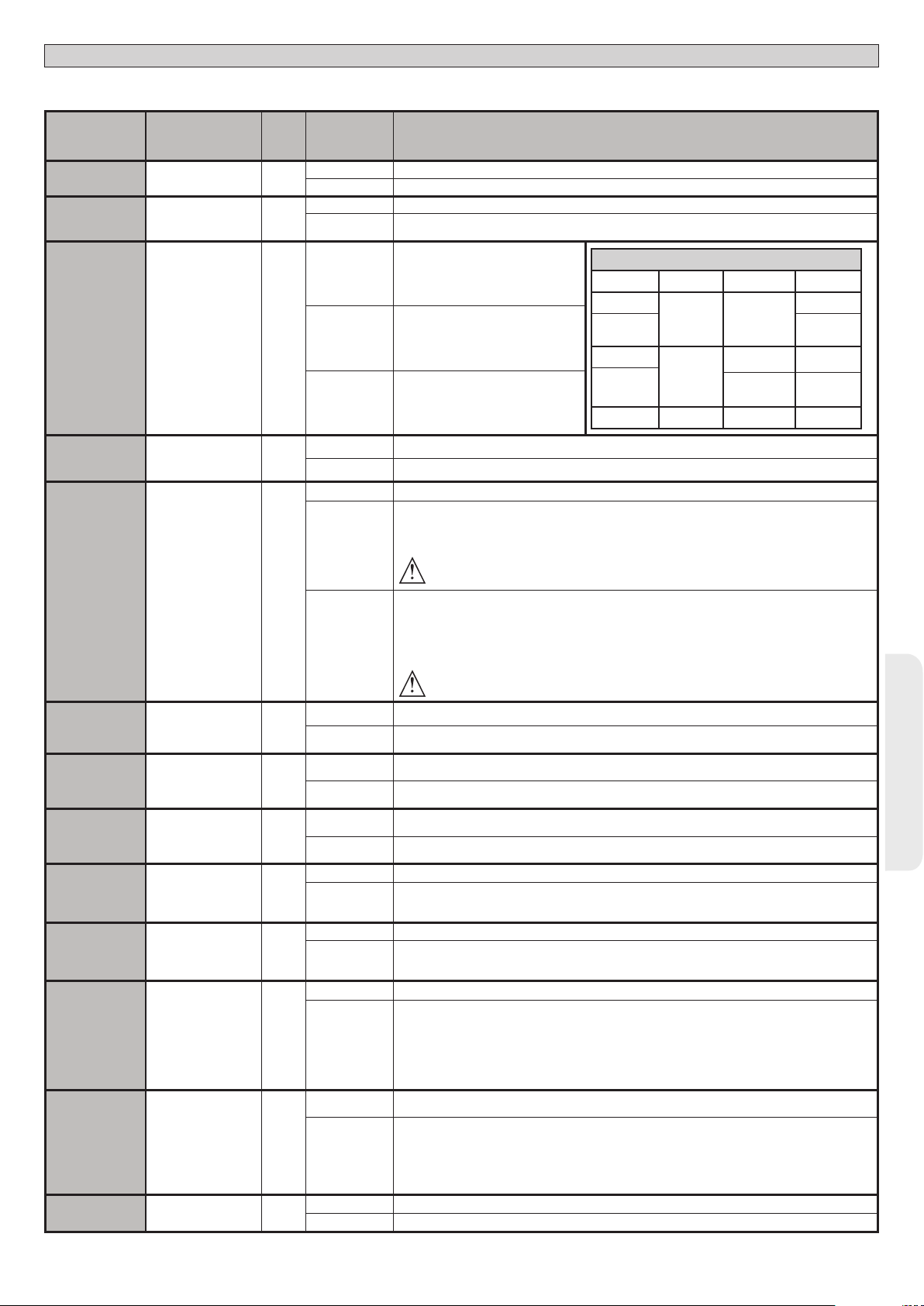
TABELLE “B” MENÜ LOGIKEN - (LOGIC)
MONTAGEANLEITUNG
D812865 00100_04
Logik Denition
TCA
SCHNELLSCHLIES.
BEW
SCHRITT
SCHRITT
VORALARM
Default
Zeit automatische
Schließung
Schnelle Schließung 0
Bewegung Schritt
Schritt
Voralarm 0
vorgenommene
0
0
Die
Einstellung
markieren
0
1
0
1
0
1
2
0
1
0
1
Optionen
Logik nicht aktiv
Aktiviert die automatische Schließung
Logik nicht aktiv
Schließt drei Sekunden nach der Freigabe der Fotozellen, ohne das Ende der eingestellten TCA
abzuwarten.
Die als Start E, Start I und Ped
kongurierten Eingänge funktionieren
mit der Logik 4 Schritte.
Die als Start E, Start I und Ped
kongurierten Eingänge funktionieren
mit der Logik 3 Schritte. Der Impuls
während der Schließungsphase kehrt
die Bewegung um.
Die als Start E, Start I und Ped
kongurierten Eingänge funktionieren
mit der Logik 2 Schritte. Bei jedem
Impuls wird die Bewegung umgekehrt.
Die Blinkleuchte geht gleichzeitig mit dem Starten des Motors / der Motoren an.
Die Blinkleuchte geht ca. drei Sekunden vor dem Starten des Motors / der Motoren an.
Funktionsweise im Impulsen.
Funktionsweise Mann anwesend.
Der Eingang 61 wird als OPEN UP konguriert.
Der Eingang 62 wird als CLOSE UP konguriert.
Das Manöver wird fortgesetzt, solange die Tasten OPEN UP oder CLOSE UP gedrückt gehalten werden.
ACHTUNG: Die Sicherheitsvorrichtungen sind nicht aktiv.
GESCHLOSSEN
SCHLIESSUNG
ÖFFNUNG
NACH STOP
Bewegung Schritt Schritt
2SCHRITT 3SCHRITT 4SCHRITT
BEI
OFFEN
BEI
ÖFFNUNG
SCHLIESSUNG
ÖFFNUNG ÖFFNUNG ÖFFNUNG
ÖFFNUNG
ÖFFNUNG
SCHLIESSUNG SCHLIESSUNG
NACH STOPP
STOPP
STOPP+ TCA
TOTMANN
IMPULSBL.
AUF
IMPULSBL.
TCA
IMPULSBL.ZU
GEGENDRUCK.
AUF
GEGENDRUCK.
ZU
DRUCSTABIL
DRUCK SWC
1 FLUGEL
Mann anwesend 0
Blockiert
Önungsimpulse
Blockiert
TCA-Impulse
Blockieren Impulse
Schließen
Widderschlag
Önung
Widderschlag
Schließung
Halten Blockierung 0
Drücken Endschalter
Schließung
1 Motor aktiv 0
Funktionsweise Mann anwesend Emergency. Normalerweise Funktionsweise mit Impulsen.
Falls die Karte den Test der Sicherheitsvorrichtungen (Fotozelle oder Leiste, Er0x) drei Mal in Folge nicht
besteht, wird die Funktionsweise Mann anwesend aktiv bis zum Loslassen der Tasten OPEN UP oder
2
0
0
0
0
0
0
0
1
0
1
0
1
0
1
0
1
0
1
0
1
0
1
CLOSE UP aktiviert.
Der Eingang 61 wird als OPEN UP konguriert.
Der Eingang 62 wird als CLOSE UP konguriert.
ACHTUNG: Mit Mann anwesend Emergency sind die Sicherheitsvorrichtungen nicht aktiv.
Der Impuls der als Start E, Start I und Ped kongurierten Eingänge hat Auswirkung während der Önung.
Der Impuls der als Start E, Start I und Ped kongurierten Eingänge hat keine Auswirkung während der
Önung.
Der Impuls der als Start E, Start I und Ped kongurierten Eingänge hat Auswirkung während der Pause
TCA.
Der Impuls der als Start E, Start I und Ped kongurierten Eingänge hat keine Auswirkung während der
Pause TCA.
Der Impuls der Eingänge, die als Start E, Start I und Ped konguriert sind, hat beim Schließen
Auswirkung.
Der Impuls der Eingänge, die als Start E, Start I und Ped konguriert sind, hat beim Schließen keine
Auswirkung.
Logik nicht aktiv
Vor der Ausführung der önung schiebt das Tor ca. 2 Sekunden in Richtung Schließung. Dies gestattet
ein einfacheres Aushaken des Elektroschlosses.
WICHTIG - Verwenden Sie diese Funktion nicht, falls keine geeigneten Anschläge vorhanden sind.
Logik nicht aktiv
Vor der Ausführung der Schließung schiebt das Tor ca. 2 Sekunden in Richtung Önung. Dies gestattet
ein einfacheres Aushaken des Elektroschlosses.
WICHTIG - Verwenden Sie diese Funktion nicht, falls keine geeigneten Anschläge vorhanden sind.
Logik nicht aktiviert
Wenn die Motoren in der Position vollständige Önung oder vollständige Schließung mehr als eine
Stunde stehen bleiben, werden sie für ca. 3 Sekunden in Richtung Anschlag aktiviert. Diese Operation
wird stündlich ausgeführt.
Anm.: Diese Funktion hat den Zweck, bei hydraulischen Motoren die eventuelle Reduzierung des
Ölvolumens durch den Abfall der Temperatur bei längeren Pausen zu kompensieren, zum Beispiel
während der Nacht oder aufgrund von interner Undichtigkeit.
WICHTIG - Verwenden Sie diese Funktion nicht, falls keine geeigneten Anschläge vorhanden sind.
Die Bewegung wird ausschließlich durch den Eingri des Anschlags Schließung angehalten; in diesem
Fall ist eine präzise Einstellung des Eingris des Anschlags Schließung erforderlich (Fig. G, Pos. B).
Zu verwenden, wenn ein Anschlag Schließung vorhanden ist.
Diese Funktion aktiviert den Druck des Flügels auf den Anschlag, ohne dass er vom Sensor Amperostop
als Hindernis angesehen wird.
Der Schaft fährt also einige Sekunden weiter, nachdem er den Endschalter Schließung erfasst hat,
oder bis zum mechanischen Anhalten. Auf diese Weise wird durch leichtes Vorverlegen der Anschläge
Schließung ein perfektes Anliegen der Flügel am Anschlag erzielt (Fig. G, Pos. A).
Beiden Motoren aktiv (2 Flügel).
Nur Motor 1 aktiv (1 Flügel).
DEUTSCH
RIGEL 6 - 69
Page 70

Logik Denition
INV RICHT
OFFNUNG
SAFE 1
SAFE 2
SAFE 3
SAFE 4
SAFE 5
SAFE 6
IC 1
IC 2
IC 3
IC 4
1ch
2ch
3ch
4ch
AUX 0
AUX 1
AUX 2
AUX 3
Richtungsumkehrung
Kongurierung des
Sicherheitseingangs
Kongurierung des
Sicherheitseingangs
Kongurierung des
Sicherheitseingangs
Kongurierung des
Sicherheitseingangs
Kongurierung des
Sicherheitseingangs
Kongurierung des
Sicherheitseingangs
Kongurierung des
Steuereingangs IC 1. 610
Kongurierung des
Steuereingangs IC 2. 624
Kongurierung des
Steuereingangs IC 3. 642
Kongurierung des
Steuereingangs IC 4. 653 6
Kongurierung des
Befehl 1. Funkkanal
Kongurierung des
Befehl 2. Funkkanal
Kongurierung des
Befehl 3. Funkkanal
Kongurierung des
Befehl 4. Funkkanal
Kongurierung des
Ausgangs AUX 0.
Kongurierung des
Ausgangs AUX 1.
Kongurierung des
Ausgangs AUX 2.
Kongurierung des
Ausgangs AUX 3.
SCHLOSS
Önung
SAFE 1.
72
SAFE 2.
74
SAFE 3.
77
SAFE 4.
79
SAFE 5.
82
SAFE 6.
84
20-21
22-23
24-25
26-27
Typ Schloss.
28-29
Default
0
0
6
2
4
0
6
0
9
2
5
6
3
1
0
0
MONTAGEANLEITUNG
Die
vorgenommene
Einstellung
markieren
0
1
0
1 Als Phot test kongurierter Eingang, überprüfte Fotozelle.
2 Als Phot op kongurierter Eingang, Fotozelle aktiv nur bei Önung.
3 Als Phot op test kongurierter Eingang, überprüfte Fotozelle aktiv nur bei Önung.
4 Als Phot cl kongurierter Eingang, Fotozelle aktiv nur bei Schließung.
5 Als Phot cl test kongurierter Eingang, überprüfte Fotozelle aktiv nur bei Schließung.
6 Als Bar kongurierter Eingang, Tastleiste.
7 Als Bar kongurierter Eingang, überprüfte Tastleiste.
8 Eingang konguriert als Bar 8k2 (Nicht aktiv an SAFE 3,4,5,6).
9
10
11
12
13
14
0
1 Als Start I kongurierter Eingang.
2 Als Open kongurierter Eingang.
3 Als Close kongurierter Eingang.
4 Als Ped kongurierter Eingang.
5 Als Timer kongurierter Eingang.
0 Befehl Funk konguriert als START E.
1 Befehl Funk konguriert als Start I.
2 Befehl Funk konguriert als Open.
3 Befehl Funk konguriert als Close
4 Befehl Funk konguriert als Ped
5 Befehl Funk konguriert als STOP
6 Befehl Funk konguriert als AUX0 **
7 Befehl Funk konguriert als AUX1**
8 Befehl Funk konguriert als AUX2**
9 Befehl Funk konguriert als AUX3**
10 Befehl Funk konguriert als EXPO1**
11 Befehl Funk konguriert als EXPO2**
0
1 Als SCA kongurierter Ausgang, Kontrollleuchte Tor oen.
2 Als Befehl Notbeleuchtung kongurierter Ausgang.
3 Als Befehl Zonenbeleuchtung kongurierter Ausgang.
4 Ausgang konguriert als Treppenbeleuchtung
5 Ausgang konguriert als Alarm
6 Ausgang konguriert als Blinkleuchte
7 Ausgang konguriert als einrastendes Schloss
8 Ausgang konguriert als Magnet-Schloss
9 Ausgang, konguriert als Wartung.
10 Ausgang, konguriert als Blinkleuchte und Wartung.
11 Nicht verwendet
12 Nicht verwendet
13 Ausgang konguriert als Status Tor
14 Ausgang konguriert als bistabiler Funkkanal
15
0
1
Funktionsweise Standard (Siehe Fig. G, Pos. C).
Die Önungsrichtung wird gegenüber der Standardfunktionsweise umgekehrt (Siehe Fig. G, Pos. D)
Als Phot kongurierter Eingang, Fotozelle.
Eingang konguriert als Bar OP, Tastleiste mit Inversion nur aktiv bei Önung. Bei Schließung wird die
Bewegung angehalten.
Eingang konguriert als Bar OP TEST, überprüfte Tastleiste mit Inversion nur aktiv bei Önung. Bei
Schließung wird die Bewegung angehalten.
Eingang konguriert als Bar OP 8k2, Tastleiste mit Inversion nur aktiv bei Önung. Bei Schließung wird
die Bewegung angehalten.
(Nicht aktiv an SAFE 3,4,5,6).
Eingang konguriert als Bar CL, Tastleiste mit Inversion nur aktiv bei Schließung. Bei Önung wird die
Bewegung angehalten.
Eingang konguriert als Bar CL TEST, überprüfte Tastleiste mit Inversion nur aktiv bei Schließung. Bei
Önung wird die Bewegung angehalten.
Eingang konguriert als Bar CL 8k2, Tastleiste mit Inversion nur aktiv bei Schließung. Bei Önung wird die
Bewegung angehalten.
(Nicht aktiv an SAFE 3,4,5,6).
Als Start E kongurierter Eingang.
Als Fußgängertimer kongurierter Eingang.
Ausgang konguriert als monostabiler Funkkanal
Ausgang konguriert als timergesteuerter Funkkanal
Ausgang konguriert für Elektroschloss mit Auslöser 12V
Ausgang konguriert für Elektroschloss mit Magnet 12V
Optionen
.
.
D812865 00100_04
70 - RIGEL 6
Page 71

D812865 00100_04
Logik Denition
FEST CODE
SCHUTZNI-
VEAU
SERIELLER
MODUS
ADRESSE
chrono
EXPI1
Fester Code 0
Einstellung des
Schutzniveaus
Serieller Modus
(Identiziert die
Kongurierung der
Karte bei einem BFT-
Netzanschluss.)
Adresse 0
Zeiträume 0
Kongurierung des
Eingangs EXPI1 der
erweiterungskarte
Eingänge/Ausgänge
1-2
Default
0
0
1
MONTAGEANLEITUNG
Die
vorgenommene
Einstellung
markieren
0
1
0
1
2
3
4
0
1
[ ___ ]
0 Logik nicht aktiv
1 Aktiviert die als Timer kongurierten Zeiträume
2 Aktiviert die als Timer Fußgänger kongurierten Zeiträume
0
1 Als Befehl Start I kongurierter Eingang.
2 Als Befehl Open kongurierter Eingang.
3 Als Befehl Close kongurierter Eingang.
4 Als Befehl Ped kongurierter Eingang.
5 Als Befehl Timer kongurierter Eingang.
6 Als Befehl Fußgänger kongurierter Eingang.
7 Als Sicherheit Phot kongurierter Eingang, Fotozelle.
8 Als Sicherheit Phot op kongurierter Eingang, Fotozelle aktiv nur bei Önung.
9 Als Sicherheit Phot cl kongurierter Eingang, Fotozelle aktiv nur bei Schließung.
10 Als Sicherheit Bar kongurierter Eingang, Tastleiste.
11
12
13
14
15
16
17
18
Der Empfänger ist für den Betrieb mit Rolling-Code konguriert.
Die Clonen mit festem Code werden nicht akzeptiert.
Der Empfänger ist für den Betrieb mit festem Code konguriert.
Die Clonen mit festem Code werden akzeptiert.
A – Das Password für den Zugang zum Menü Programmierung wird nicht angefordert.
B - Aktiviert die Abspeicherung der Fernbedienungen über Funk.
Diese Modalität wird in der Nähe der Bedientafel ausgeführt und macht keinen Zugang erforderlich:
- Drücken Sie nacheinander die versteckte Taste und die normale Taste (T1-T2-T3-T4) eines bereits in der
Standardmodalität mit dem Menü Funk abgespeicherten Senders.
- Drücken Sie innerhalb von 10 Sekunden die versteckte Taste und die normale Taste (T1-T2-T3-T4) einer
abzuspeichernden Fernbedienung.
Der Empfänger verlässt die Programmiermodalität nach 10 Sekunden, innerhalb dieser Zeit können
durch Wiederholung des vorausgehenden Punkts weitere neue Fernbedienungen eingegeben werden.
C – Die automatische Eingabe der Klone über Funk wird aktiviert.
Gestattet die Hinzufügung der mit der Universalprogrammiereinheit erstellten Klone sowie der programmierten Replays zum Speicher des Empfängers.
D – Die automatische Eingabe der Replay über Funk wird aktiviert.
Gestattet das Hinzufügen der programmierten Replay zum Speicher des Empfängers.
E – Die Parameter der Karte können über das Netz U-link geändert werden.
A – Das Password für den Zugang zum Programmierungsmenü wird angefordert.
Das Default-Password ist 1234:
Die Funktionen B – C – D – E bleiben bezogen auf die Funktionsweise 0 unverändert.
A – Das Password für den Zugang zum Menü Programmierung wird angefordert.
Das Default-Password ist 1234:
B – Die Abspeicherung der Fernbedienungen über Funk wird deaktiviert.
C – Die automatische Eingabe der Klone über Funk wird deaktiviert.
Die Funktionen D – E bleiben bezogen auf die Funktionsweise 0 unverändert.
A – Das Password für den Zugang zum Menü Programmierung wird angefordert.
Das Default-Password ist 1234:
B – Die Abspeicherung der Fernbedienungen über Funk wird deaktiviert.
D– Die automatische Eingabe der Replay über Funk wird deaktiviert.
Die Funktion E bleibt bezogen auf die Funktionsweise 0 unverändert.
A – Das Password für den Zugang zum Menü Programmierung wird angefordert.
Das Default-Password ist 1234:
B – Die Abspeicherung der Fernbedienungen über Funk wird deaktiviert.
C – Die automatische Eingabe der Klone über Funk wird deaktiviert.
D – Die automatische Eingabe der Replay über Funk wird deaktiviert.
E – Die Möglichkeit der Änderung der Parameter der Karte über das Netz U-link wird deaktiviert.
Die Fernbedienungen werden nur mit dem entsprechen Menü Funk abgespeichert.
WICHTIG: Dieses hohe Sicherheitsniveau verhindert sowohl den Zugri durch unerwünschte Klone, als
auch gegebenenfalls vorhandene Funkstörungen.
SLAVE Standard: Die Karte empfängt und sendet Befehle/Diagnose/usw.
MASTER Standard: Die Karte sendet Aktivierungsbefehle (START, OPEN, CLOSE, PED, STOP) und andere
Karten.
Identiziert die Adresse von 0 bis 119 der Karte in einer lokalen BFT-Netzverbindung.
(siehe Abschnitt OPTIONALE MODULE U-LINK)
Als Befehl Start E kongurierter Eingang.
Eingang konguriert als Sicherheit Bar OP, Tastleiste mit Inversion nur aktiv bei Önung, bei Schließung
wird die Bewegung angehalten.
Eingang konguriert als Sicherheit Bar CL, Tastleiste mit Inversion nur aktiv bei Schließung, bei Önung
wird die Bewegung angehalten.
Als Sicherheit Phot test kongurierter Eingang, überprüfte Fotozelle. Der Eingang 3 (EXPI2) der Erweiterungskarte Eingänge/Ausgänge wird automatisch auf Eingang Überprüfung Sicherheitsvorrichtungen
umgeschaltet, EXPFAULT1.
Eingang konguriert als Sicherheit Phot op test, überprüfte Fotozelle nur aktiv bei Önung. Der Eingang 3
(EXPI2) der Erweiterungskarte Eingänge/Ausgänge wird automatisch umgeschaltet auf Eingang Überprüfung
Sicherheitsvorrichtungen, EXPFAULT1.
Eingang konguriert als Sicherheit Phot cl test, überprüfte Fotozelle nur aktiv bei Schließung. Der Eingang 3
(EXPI2) der Erweiterungskarte Eingänge/Ausgänge wird automatisch umgeschaltet auf Eingang Überprüfung
Sicherheitsvorrichtungen, EXPFAULT1.
Als Sicherheit Bar kongurierter Eingang, überprüfte Tastleiste. Der Eingang 3 (EXPI2) der Er weiterungskarte
Eingänge/Ausgänge wird automatisch auf Eingang Überprüfung Sicherheitsvorrichtungen umgeschaltet,
EXPFAULT1.
Eingang konguriert als Sicherheit Bar OP test, überprüfte Tastleiste mit Inversion nur aktiv bei Önung,
bei Schließung wird die Bewegung angehalten. Der Eingang 3 (EXPI2) der Erweiterungskarte Eingänge/
Ausgänge wird automatisch auf Eingang Überprüfung Sicherheitsvorrichtungen umgeschaltet, EXPFAULT1.
Eingang konguriert als Sicherheit Bar CL test, überprüfte Tastleiste mit Inversion nur aktiv bei Schließung,
bei Önung wird die Bewegung angehalten. Der Eingang 3 (EXPI2) der Erweiterungskarte Eingänge/
Ausgänge wird automatisch auf Eingang Überprüfung Sicherheitsvorrichtungen umgeschaltet, EXPFAULT1.
Optionen
DEUTSCH
RIGEL 6 - 71
Page 72

Logik Denition
Kongurierung des
Eingangs EXPI2 der
EXPI2
EXPO1
EXPO2
AMPEL
VORBLINKEN
AMPEL
FESTROTE
erweiterungskarte
Eingänge/Ausgänge
Kongurierung des
Ausgangs EXPO2 der
Erweiterungskarte
Eingänge/Ausgänge
Kongurierung des
Ausgangs EXPO2 der
Erweiterungskarte
Eingänge/Ausgänge
Vorblinken Ampel 0
Ampel dauerhaft rot 0
1-3
4-5
6-7
Default
0
11
11
MONTAGEANLEITUNG
Die
vorgenommene
Einstellung
markieren
0
1 Als Befehl Start I kongurierter Eingang.
2 Als Befehl Open kongurierter Eingang.
3 Als Befehl Close kongurierter Eingang.
4 Als Befehl Ped kongurierter Eingang.
5 Als Befehl Timer kongurierter Eingang.
6 Als Befehl Fußgänger kongurierter Eingang.
7 Als Sicherheit Phot kongurierter Eingang, Fotozelle.
8 Als Sicherheit Phot op kongurierter Eingang, Fotozelle aktiv nur bei Önung.
9 Als Sicherheit Phot cl kongurierter Eingang, Fotozelle aktiv nur bei Schließung.
10 Als Sicherheit Bar kongurierter Eingang, Tastleiste.
11
12
0
1 Als SCA kongurierter Ausgang, Kontrollleuchte Tor oen.
2 Als Befehl Notbeleuchtung kongurierter Ausgang.
3 Als Befehl Zonenbeleuchtung kongurierter Ausgang.
4 Ausgang konguriert als Treppenbeleuchtung.
5 Ausgang konguriert als Alarm.
6 Ausgang konguriert als Blinkleuchte.
7 Ausgang konguriert als einrastendes Schloss.
8 Ausgang konguriert als Magnet-Schloss.
9 Ausgang, konguriert als Wartung.
10
11
12
13
14
15
0
1
0
1
Als Befehl Start E kongurierter Eingang.
Eingang konguriert als Sicherheit Bar OP, Tastleiste mit Inversion nur aktiv bei Önung, bei Schließung
wird die Bewegung angehalten.
Eingang konguriert als Sicherheit Bar CL, Tastleiste mit Inversion nur aktiv bei Schließung, bei Önung
wird die Bewegung angehalten.
Ausgang konguriert als monostabiler Funkkanal
Ausgang, konguriert als Blinkleuchte und Wartung.
Ausgang konguriert als Steuerung Ampel mit Karte TLB.
Nicht verwendet
Ausgang konguriert als Status Tor
Ausgang konguriert als bistabiler Funkkanal
Ausgang konguriert als timergesteuerter Funkkanal
Vorblinken ausgeschlossen.
Rote Blinkleuchten für drei Sekunden bei Beginn des Manövers.
Rote Leuchten aus bei geschlossenem Tor.
Rote Leuchten an bei geschlossenem Tor.
Optionen
D812865 00100_04
Kongurierung der Befehle Funkkanal
LogiK CH= 0 - Eingang konguriert als Start E. Funktionsweise gemäß Logik MOV. SCHRITT SCHRITT. Externer Start für Ampelsteuerung.
LogiK CH= 1 - Eingang konguriert als Start I. Funktionsweise gemäß Logik MOV. SCHRITT SCHRITT. Interner Start für Ampelsteuerung.
LogiK CH= 2 - Eingang konguriert als Open.
Der Befehl führt eine Önung aus.
LogiK CH= 3 - Eingang konguriert als Close.
Der Befehl führt die Schließung aus.
LogiK CH= 4 - Eingang konguriert als Ped.
Der Befehl führt eine partielle Fußgängerönung aus. Funktionsweise gemäß Logik MOV. SCHRITT SCHRITT
LogiK CH= 5- Eingang konguriert als STOP.
Der Befehl führt einen Stopp aus.
LogiK CH= 6- Eingang konguriert als AUX0. (**)
Der Befehl aktiviert den Ausgang AUX0
LogiK CH= 7- Eingang konguriert als AUX1. (**)
Der Befehl aktiviert den Ausgang AUX1
LogiK= 8- Eingang konguriert als AUX2. (**)
Der Befehl aktiviert den Ausgang AUX 2
LogiK CH= 9- Eingang konguriert als AUX3. (**)
Der Befehl aktiviert den Ausgang AUX3
LogiK CH= 10- Eingang konguriert als EXPO1. (**)
Der Befehl aktiviert den Ausganga EXPO1
LogiK CH= 11- Eingang konguriert als EXPO2. (**)
Der Befehl aktiviert den Ausgang EXPO2
** Nur aktiv, wenn der Ausgang als monostabiler Funkkanal, Notbeleuchtung, Zonenbeleuchtung, Treppenbeleuchtung, bistabiler Funkkanal oder timergesteuerter Funkkanal konguriert ist.
72 - RIGEL 6
Page 73

TABELLE “C” MENÜ FUNK RADIO
D812865 00100_04
Logik Beschreibung
zufueg 1ch
zufueg 2ch
zufueg 3ch
zufueg 4ch
Hinzufügen Taste 1ch
Ordnet die gewünschte Taste dem Befehl 1. Funkkanal zu.
Hinzufügen Taste 2ch
Ordnet die gewünschte Taste dem Befehl 2. Funkkanal zu.
Hinzufügen Taste 1ch
Ordnet die gewünschte Taste dem Befehl 3. Funkkanal zu.
Hinzufügen Taste 2ch
Ordnet die gewünschte Taste dem Befehl 4. Funkkanal zu.
Liste löschen
loeschen 64
Löscht einzelne Fernbedienung
loeschen 1
Entfernt eine Fernbedienung (wird bei Clone oder Replay deaktiviert). Schreiben Sie zum Auswählen der zu löschenden Fernbedienung die
Position oder drücken Sie die Taste der zu löschenden Fernbedienung (die Position wird angezeigt)
Lesung Code Empfänger
Zeigt den Code des Empfängers an, der für das Clonen der Fernbedienungen erforderlich ist.
ACHTUNG! Entfernt alle abgespeicherten Fernbedienungen vollständig aus dem Speicher des Empfängers.
MONTAGEANLEITUNG
DEUTSCH
RIGEL 6 - 73
Page 74

x2
ACCESO A LOS MENUS Fig. 1
MANUAL DE INSTALACIÓN
***
0---
ALT seguir manual
elimina 1 ( 0001 )
anad 1ch
anad 2ch
anad 3ch
anad 4ch
canc 64
10--
tecla escond
tecla escond
tecla escond
tecla escond
150- 1520 ok
Véase MENÚ PARÁMETROS
Véase MENÚ LÓGICAS
suelte
tecla deseada
suelte
tecla deseada
suelte
tecla deseada
suelte
tecla deseada
o
Si está borrado
o
Si no está presente
Si se deshabilita clone.
dis
*** Introducción contraseña.
Solicitud con lógica Nivel
Protección congurada a 1, 2, 3, 4
Véase MENÚ RADIO
D812865 00100_04
LEGENDA
Desplazar hacia arriba
Desplazar hacia abajo
Conrmación/
Encendido pantalla
Retorno al menú
principal
LANG
autoset
stat
Para el menú AUTOSET
véase el menú
simplificado
Versión software central
OK
vers
+
n. an
+
n. teleco
+
err
bft . . .
+/-
N° de maniobras totales (x 100)
OK
0000
+/-
N° de radiomandos memorizados
OK
00
+/-
Lista últimos 30 errores
OK
01.33
02.01
........
30.15
+/-
Código
diagnóstico
STRE
STRI
OPEN
CLS
PED
TIME
STOP
PHOT
PHOP
PHCL
BAR
baro
barc
SWC1
SWO1
SWC2
SWO2
ER01
ER02
ER03
ER04
er06
ER07
ER08
ER1x*
ER3x*
ER7x*
ERf3
ERF9
Activación entrada start externo START E
Activación entrada start interno START I
Activación entrada OPEN
Activación entrada CLOSE
Activación entrada peatonal PED
Activación entrada TIMER o activación franja horaria
programada
Activación entrada STOP
Activación entrada fotocélula PHOT o si está congurada
como fotocélula comprobada Activación de la entrada
FAULT asociada
Activación entrada fotocélula en fase de apertura PHOT
OP o si está congurada como fotocélula comprobada
activa solo en fase de apertura Activación de la entrada
FAULT asociada
Activación entrada fotocélula en fase de cierre PHOT CL o si
está congurada como fotocélula comprobada activa solo
en fase de cierre Activación de la entrada FAULT asociada
Activación entrada canto BAR o si está congurada como canto
sensible comprobado Activación de la entrada FAULT asociada
Activación entrada canto BAR con inversión ACTIVA SOLO
EN FASE DE APERTURA o si está congurada como canto
sensible comprobado activo solo en fase de apertura,
Activación de la entrada FAULT asociada
Activación entrada canto BAR con inversión ACTIVA
SOLO EN FASE DE CIERRE o si está congurada como
canto sensible comprobado activo solo en fase de cierre,
Activación de la entrada FAULT asociada
Activación entrada nal de carrera cierre del motor 1 SWC1
Activación entrada final de carrera apertura del motor 1 SWO1
Activación entrada nal de carrera cierre del motor 2 SWC2
Activación entrada final de carrera apertura del motor 2 SWO2
Prueba fotocélulas fallida Comprobar conexión fotocélulas y/o conguraciones lógicas
Prueba canto fallida Comprobar conexión cantos y/o conguraciones lógicas
Prueba fotocélulas apertura fallida
Prueba fotocélulas cierre fallida
Prueba canto 8k2 fallida
Prueba canto apertura fallida
Prueba canto cierre fallida
Error prueba hardware tarjeta
Inversión por obstáculo - Amperio-stop Comprobar eventuales obstáculos a lo largo del recorrido
Error interno de control supervisión sistema.
error en la conguración de las entradas SAFE Comprobar la correcta conguración de las entradas SAFE
Sobrecarga salida cerradura eléctrica
DESCRIPCIÓN NOTAS
*X= 0, 1, .., 9, A, B, C, D, E, F
comprobar conexión fotocélulas y/o configuración
parámetros/lógicas
comprobar conexión fotocélulas y/o configuración
parámetros/lógicas
Comprobar conexión cantos y/o configuraciones
parámetros/lógicas
Comprobar conexión cantos y/o conguraciones
parámetros/lógicas
Comprobar conexión cantos y/o conguraciones
parámetros/lógicas
- Comprobar conexiones al motor
- Problemas hardware en la tarjeta (contactar con la
asistencia técnica)
Probar apagar y volver a encender la tarjeta. Si el problema
persiste, contactar con la asistencia técnica.
- Comprobar conexiones cerradura
- Cerradura no adecuada
password
74 - RIGEL 6
0---
10--
150- 1520 prg
Page 75
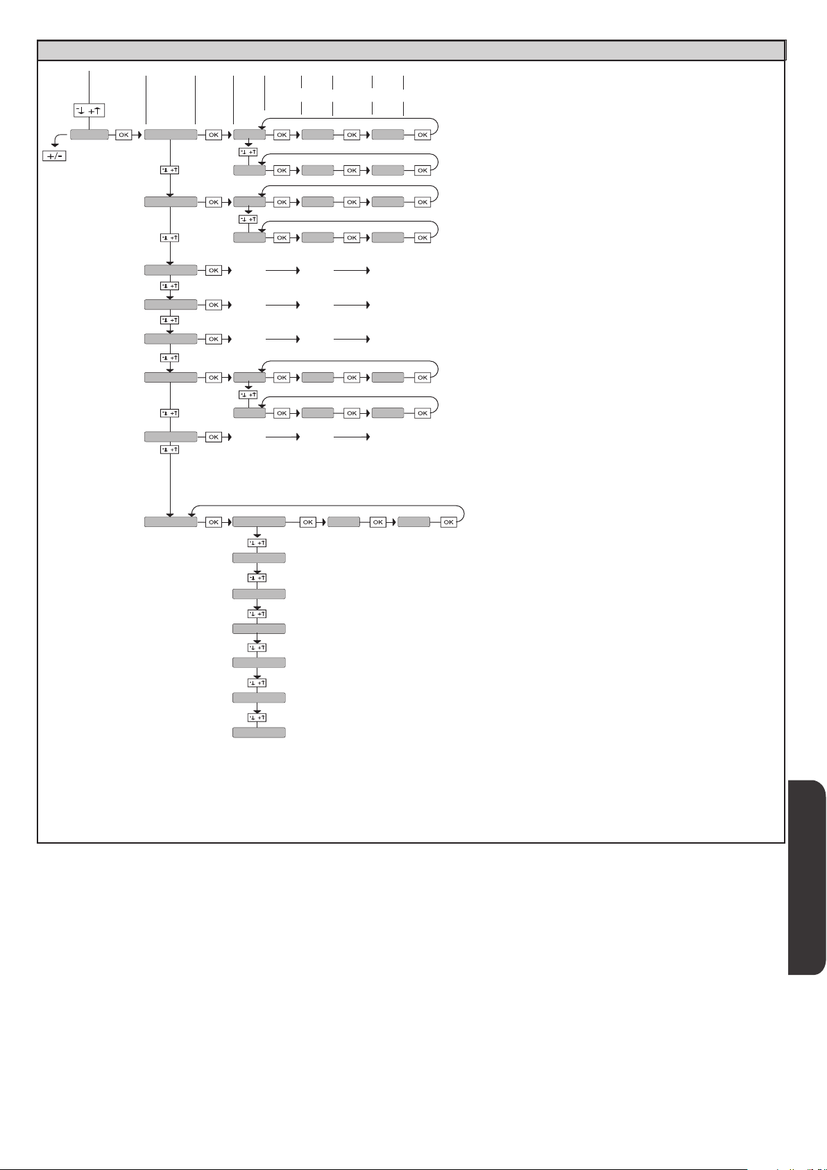
MANUAL DE INSTALACIÓN
ACCESO A LOS MENUS Fig. 1
D812865 00100_04
DÍA
domingo 01 10-0 12-0chrono
lunes
martes
miercoles
jueves
|viernes
sabado
FRANJA
02 00-0 00-0
01 07-0 12-0
02 14-0 18-0
.... .... ....
.... .... ....
.... .... ....
01 07-0 12-0
02 14-0 18-0
.... .... ....
INICIO FINAL
[00:00 - 24:00] [00:00 - 24:00]
domingo
lunes
martes
miercoles
jueves
|viernes
sabado
00 00hh-MM
[00-23]
Ajustar hora
[00:59]
Ajustar minutos
Ajuste reloj
ESPAÑOL
RIGEL 6 - 75
Page 76

MANUAL DE INSTALACIÓN
2) GENERALIDADES
El cuadro de mandos RIGEL 6 es entregado por el fabricante con conguración
estándar. Cualquier modicación debe ser congurada mediante el programador
con pantalla incorporado o mediante programador portátil universal.
La Central soporta completamente el protocolo EELINK.
Las características principales son:
- Control de 1 o 2 motores monofásicos con pastilla termomagnética
Nota: Se deben utilizar 2 motores del mismo tipo.
- Ajuste electrónico del par
- Entradas control nal de carrera cierre/apertura separadas para cada motor
- Entradas separadas para los dispositivos de seguridad
- Gestión franjas horarias
- Detección obstáculo integrado
- Precalentamiento motores con lectura sonda integrado
- Frenado electrodinámico regulable
- Deceleración de la velocidad de aproximación
- Receptor radio incorporado rolling-code con clonación transmisores.
La tarjeta cuenta con tablero de bornes desmontable para facilitar aún más su
mantenimiento o sustitución. Es entregada con una serie de puentes precableados
para facilitar su instalación en obra.
Los puentes corresponden a los bornes: 41-42, 41-43, 41-44, 41-45, 70-71,
70-72, 70-74, 76-77, 76-79, 81-82, 81-84. Si los bornes antes indicados son
utilizados, quitar sus respectivos puentes.
COMPROBACIÓN
El cuadro RIGEL 6 realiza el control (comprobación) de los relés de marcha, de los
TRIAC y de los dispositivos de seguridad (fotocélulas y cantos), antes de realizar
cada ciclo de apertura y cierre.
En caso de defectos de funcionamiento, comprobar que los dispositivos
conectados funcionen correctamente y controlar los cableados.
ATENCIÓN!: si la puerta está en instalada en un área pública o bien si está habilitada una modalidad de funcionamiento automática, se recomienda instalar
un par de fotocélulas a 5 cm y otro par a 40-50 cm de altura. Con modalidad
automática se hace referencia a cualquier mando no activado de forma voluntaria
por el usuario (por ejemplo: función TCA, chrono, etc.).
3) DATOS TÉCNICOS
Alimentación 220-230V 50/60Hz(*)
Aislamiento red/baja tensión > 2MOhm 500V
Resistencia dieléctrica rete/bt 3750V~ por 1 minuto
Alimentación accesorios
24V~ (1A absorción máx.)
24V~safe
AUX 0
AUX 1
AUX 2
Contacto alineado
220-230V N.O. (80W MAX)
Contacto alineado
220-230V N.O. (80W MAX)
Contacto N.O.
(MAX 220-230V~ 80W)
AUX0+
AUX1+
AUX2=
80W
MÁX.
AUX 3 Contacto N.O. (Max 24V~) 10W MÁX.
LOCK
Salida para cerradura eléctrica
12V :
10W MÁX.
Fusibles véase Fig. B
N° combinaciones: 4 mil millones
N° máx. radiomandos
memorizables:
63
(* otras tensiones disponibles bajo pedido)
Ciclo de uso continuo continuo 1 min. ON/
Temperatura
de funcionamiento
Potencia máxima
motores 220-230V
Potencia máxima
motores 110-120V
-20°C/+50°C -20°C/+55°C -20°C/+50°C -20°C/+55°C
2x375 W
1x750 W
2x320 W
1x390 W
2x250 W
1x500 W
2 min. OFF
2x650 W
1x750 W
1 min. ON/
2 min. OFF
2x500 W
1x750 W
M1+M2+AUX0+AUX1+AUX2+AUX3+LOCK= 1300W MAX T=+50°C
Versiones de transmisores que se pueden utilizar:
Todos los transmisores ROLLING CODE compatibles con
4) DISPOSICIÓN DE TUBOS Fig. A
5) CONEXIONES TABLERO DE BORNES Fig. B
ADVERTENCIAS - En las operaciones de cableado e instalación seguir las normas
vigentes y los principios de buena técnica.
Los conductores alimentados con tensiones diferentes deben estar físicamente
separados, o bien deben estar debidamente aislados con aislamiento
suplementario de al menos 1 mm.
Los conductores deben estar unidos por una jación suplementaria cerca de los
bornes, por ejemplo mediante abrazaderas.
Todos los cables de conexión deben ser mantenidos adecuadamente alejados
del disipador.
D812865 00100_04
Alimenta-
Motor
Aux
Final
Borne Denición Descripción
L FASE
ción
de carrera
N NEUTRO
GND TIERRA
10 MOT1 MARCHA
11 MOT1 COM
12 MOT1 MARCHA
14 MOT2 MARCHA
15 MOT2 COM
16 MOT2 MARCHA
20
21
22
23
24
25
26
27
28
29
40 No utilizado
41 + REF SWE Común nal de carrera
42 SWC 1 Final de carrera de cierre del motor 1 SWC1 (N.C.).
43 SWO 1 Final de carrera de apertura del motor 1 SWO1 (N.C.).
44 SWC 2 Final de carrera de cierre del motor 2 SWC2 (N.C.).
45 SWO 2 Final de carrera de apertura del motor 2 SWO2 (N.C.).
AUX 0 - CONTACTO ALIMENTADO
AUX 1 - CONTACTO ALIMENTADO
220-230V~
220-230V~
AUX 2 - CONTACTO LIBRE (N.O.)
AUX 3 - CONTACTO LIBRE (N.O.)
LOCK 12V
Alimentación monofásica 220-230V~ ±10%, 50-60Hz.
Conexión motor 1. Desfasaje retardado en fase de cierre.
Conexión motor 2. Desfasaje retardado en fase de apertura.
Nota: si el «1 MOT.ACTIV»=1 no conectar ningún cable en los bornes 14-15-16
Salida congurable AUX 0 - Default PARPADEANTE.
CANAL RADIO MONOESTABLE/ INDICADOR CANCELA ABIERTA SCA/ Mando LUZ CORTESÍA/ Mando LUZ ZONA/
LUZ ESCALERAS/ ALARMA CANCELA ABIERTA/ INDICADOR PARPADEANTE/ CERRADURA ELÉCTRICA DE RESORTE/
CERRADURA ELÉCTRICA CON IMANES/MANTENIMIENTO/PARPADEANTE Y MANTENIMIENTO / ESTADO CANCELA /
CANAL RADIO BIESTABLE / CANAL RADIO TEMPORIZADO.
Consultar la tabla “Conguración de las salidas AUX”.
Salida congurable AUX 1 - Default Salida LUZ ZONA.
CANAL RADIO MONOESTABLE/ INDICADOR CANCELA ABIERTA SCA/ Mando LUZ CORTESÍA/ Mando LUZ ZONA/
LUZ ESCALERAS/ ALARMA CANCELA ABIERTA/ INDICADOR PARPADEANTE/ CERRADURA ELÉCTRICA DE RESORTE/
CERRADURA ELÉCTRICA CON IMANES/MANTENIMIENTO/PARPADEANTE Y MANTENIMIENTO / ESTADO CANCELA /
CANAL RADIO BIESTABLE / CANAL RADIO TEMPORIZADO.
Consultar la tabla “Conguración de las salidas AUX”.
Salida congurable AUX 2 - Default Salida INDICADOR CANCELA ABIERTA SCA.
CANAL RADIO MONOESTABLE/ INDICADOR CANCELA ABIERTA SCA/ Mando LUZ CORTESÍA/ Mando LUZ ZONA/
LUZ ESCALERAS/ ALARMA CANCELA ABIERTA/ INDICADOR PARPADEANTE/ CERRADURA ELÉCTRICA DE RESORTE/
CERRADURA ELÉCTRICA CON IMANES/MANTENIMIENTO/PARPADEANTE Y MANTENIMIENTO / ESTADO CANCELA /
CANAL RADIO BIESTABLE / CANAL RADIO TEMPORIZADO.
Consultar la tabla “Conguración de las salidas AUX”.
Salida congurable AUX 3 - Default Salida 2°CANAL RADIO.
CANAL RADIO MONOESTABLE/ INDICADOR CANCELA ABIERTA SCA/ Mando LUZ CORTESÍA/ Mando LUZ ZONA/
LUZ ESCALERAS/ ALARMA CANCELA ABIERTA/ INDICADOR PARPADEANTE/ CERRADURA ELÉCTRICA DE RESORTE/
CERRADURA ELÉCTRICA CON IMANES/MANTENIMIENTO/PARPADEANTE Y MANTENIMIENTO / ESTADO CANCELA /
CANAL RADIO BIESTABLE / CANAL RADIO TEMPORIZADO.
Consultar la tabla “Conguración de las salidas AUX”.
Lógica Tipo cerradura= 0 – Salida cerradura eléctrica de resorte 12V
Salida activada con un impulso encada apertura y cierre
Lógica Tipo cerradura= 1 – Salida cerradura eléctrica con imanes 12V
Salida Activada con cancela cerrada y en fase de cierre
(MODELO ECB)
76 - RIGEL 6
Page 77

D812865 00100_04
accesorios
Alimentación
Mandos
Dispositivos de seguridad
Antena
NTC
MANUAL DE INSTALACIÓN
Borne Denición Descripción
50 24V-
51 24V+
52 24 Vsafe+
60 Común Común entradas IC 1 y IC 2
61 IC 1
62 IC 2
63 Común Común entradas I3 1 y IC 4
64 IC 3
65 IC 4
70 Común Común entradas STOP, SAFE 1 y SAFE 2
71 STOP
72 SAFE 1
73 FAULT 1 Entrada comprobación dispositivos de seguridad conectados al SAFE 1.
74 SAFE 2
75 FAULT 2 Entrada comprobación dispositivos de seguridad conectados al SAFE 2.
76 Común Común entradas SAFE 3 y SAFE 4
77 SAFE 3
78 FAULT 3 Entrada comprobación dispositivos de seguridad conectados al SAFE 3.
79 SAFE 4
80 FAULT 4 Entrada comprobación dispositivos de seguridad conectados al SAFE 4.
81 Común Común entradas SAFE 5 y SAFE 6
82 SAFE 5
83 FAULT 5 Entrada comprobación dispositivos de seguridad conectados al SAFE 5.
84 SAFE 6
85 FAULT 6 Entrada comprobación dispositivos de seguridad conectados al SAFE 6.
Y ANTENA
# SHIELD
NTC Entrada para conexión de la sonda de temperatura
Salida alimentación accesorios.
Salida alimentación para dispositivos de seguridad comprados (transmisor fotocélulas y transmisor canto sensible).
Salida activa sólo durante el ciclo de maniobra.
Entrada de mando congurable 1 (N.O.) - Default START E.
START E / START I / OPEN / CLOSE / PED / TIMER / TIMER PED
Consultar la tabla "Conguración de las entradas de mando".
Entrada de mando congurable 2 (N.O.) - Default PED.
START E / START I / OPEN / CLOSE / PED / TIMER / TIMER PED
Consultar la tabla "Conguración de las entradas de mando".
Entrada de mando congurable 3 (N.O.) - Default OPEN.
START E / START I / OPEN / CLOSE / PED / TIMER / TIMER PED
Consultar la tabla "Conguración de las entradas de mando".
Entrada de mando congurable 4 (N.O.) - Default CLOSE.
START E / START I / OPEN / CLOSE / PED / TIMER / TIMER PED
Consultar la tabla "Conguración de las entradas de mando".
El mando interrumpe la maniobra. (N.C.)
Si no se utiliza, dejar el puente conectado.
Entrada de seguridad congurable 1 (N.C.) - Default PHOT.
PHOT / PHOT TEST / PHOT OP / PHOT OP TEST / PHOT CL / PHOT CL TEST / BAR / BAR TEST / BAR 8K2/ B
OP/ BAR CL / BAR CL TEST / BAR 8K2 CL
Consultar la tabla "Conguración de las entradas de seguridad".
Entrada de seguridad congurable 2 (N.C.) - Default BAR.
PHOT / PHOT TEST / PHOT OP / PHOT OP TEST / PHOT CL / PHOT CL TEST / BAR / BAR TEST / BAR 8K2/ B
OP/ BAR CL / BAR CL TEST / BAR 8K2 CL
Consultar la tabla "Conguración de las entradas de seguridad".
Entrada de seguridad congurable 3 (N.C.) - Default PHOT OP.
PHOT / PHOT TEST / PHOT OP / PHOT OP TEST / PHOT CL / PHOT CL TEST / BAR / BAR TEST / BAR OP / BAR OP TEST / BAR CL / BAR CL TEST /
Consultar la tabla "Conguración de las entradas de seguridad".
Entrada de seguridad congurable 4 (N.C.) - Default PHOT CL.
PHOT / PHOT TEST / PHOT OP / PHOT OP TEST / PHOT CL / PHOT CL TEST / BAR / BAR TEST / BAR OP / BAR OP TEST / BAR CL / BAR CL TEST /
Consultar la tabla "Conguración de las entradas de seguridad".
Entrada de seguridad congurable 5 (N.C.) - Default PHOT.
PHOT / PHOT TEST / PHOT OP / PHOT OP TEST / PHOT CL / PHOT CL TEST / BAR / BAR TEST / BAR OP / BAR OP TEST / BAR CL / BAR CL TEST /
Consultar la tabla "Conguración de las entradas de seguridad".
Entrada de seguridad congurable 6 (N.C.) - Default BAR.
PHOT / PHOT TEST / PHOT OP / PHOT OP TEST / PHOT CL / PHOT CL TEST / BAR / BAR TEST / BAR OP / BAR OP TEST / BAR CL / BAR CL TEST /
Consultar la tabla "Conguración de las entradas de seguridad".
Entrada antena.
Usar una antena sintonizada en 433 MHz. Para la conexión Antena-Receptor, usar cable coaxial RG58. La presencia de cuerpos
metálicos junto a la antena, puede perturbar la recepción radio. En caso de alcance escaso del transmisor, hay que situar la antena
en un punto más adecuado.
AR OP / BAR OP TEST / BAR 8K2
AR OP / BAR OP TEST / BAR 8K2
Conguración de las salidas AUX
Lógica Aux= 0 - Salida CANAL RADIO MONOESTABLE.
El contacto permanece cerrado durante 1 seg. cuando se activa el canal radio.
Lógica Aux= 1 - Salida INDICADOR CANCELA ABIERTA SCA.
El contacto permanece cerrado durante la fase de apertura y con la hoja abierta, intermitente durante la fase de cierre, abierto con hoja cerrada.
Lógica Aux= 2 - Salida mando LUZ DE CORTESÍA.
El contacto permanece cerrado durante 90 segundos después de la última maniobra.
Lógica Aux= 3 - Salida mando LUZ DE ZONA.
El contacto permanece cerrado durante todo la maniobra.
Lógica Aux= 4 – Salida LUZ ESCALERAS.
El contacto queda cerrado durante 1 segundo al comienzo de la maniobra.
Lógica Aux= 5 – Salida ALARMA CANCELA ABIERTA.
El contacto queda cerrado si la hoja queda abierta durante un tiempo doble respecto al TCA congurado.
Lógica Aux= 6 – Salida para INDICADOR PARPADEANTE.
El contacto queda cerrado durante el desplazamiento de las hojas.
Lógica Aux= 7 – Salida para CERRADURA ELÉCTRICA DE RESORTE.
El contacto queda cerrado durante 2 segundos en cada apertura y en cada cierre.
Lógica Aux= 8 – Salida para CERRADURA ELÉCTRICA CON IMANES.
El contacto queda cerrado con la cancela cerrada y durante la maniobra de cierre.
Lógica Aux= 9 – Salida MANTENIMIENTO.
El contacto permanece cerrado cuando se alcanza el valor congurado en el parámetro Mantenimiento, para señalar la solicitud de mantenimiento.
Lógica Aux= 10 – Salida PARPADEANTE Y MANTENIMIENTO.
El contacto queda cerrado durante el desplazamiento de las hojas. Si se alcanza el valor congurado en el parámetro Mantenimiento, al nal de la maniobra, con hoja cerrada, el contacto
por 4 veces se cierra durante 10 s y se abre durante 5 s para señalar la solicitud de mantenimiento.
Lógica Aux= 11 - No Disponible
Lógica Aux= 12 - No Disponible
Lógica AUX= 13 - Salida ESTADO CANCELA.
El contacto queda cerrado cuando la cancela está cerrada.
RIGEL 6 - 77
ESPAÑOL
Page 78

MANUAL DE INSTALACIÓN
Lógica AUX= 14 - Salida CANAL RADIO BIESTABLE
El contacto cambia de estado (abierto-cerrado) cuando se activa el canal radio
Lógica AUX= 15 - Salida CANAL RADIO TEMPORIZADA
El contacto queda cerrado durante un tiempo programable cuando se activa el canal Radio (tiempo salida)
Si durante dicho tiempo se pulsa nuevamente la tecla, se reanuda el conteo del tiempo.
Conguración de las entradas de mando
Lógica IC= 0 - Entrada congurada como Start E. Funcionamiento según la L|gica MOV. PASO PASO. Start externo para la gestión semáforo.
Lógica IC= 1 - Entrada congurada como Start I. Funcionamiento según la L|gica MOV. PASO PASO. Start interno para la gestión semáforo.
Lógica IC= 2 - Entrada congurada como Open.
El mando realiza una apertura. Si la entrada permanece cerrada, las hojas permanecen abiertas hasta la apertura del contacto. Con contacto abierto la automatización se cierra
después del tiempo de tca, si estuviera activado.
Lógica IC= 3 - Entrada congurada como Close.
El mando realiza una fase de cierre.
Lógica IC= 4 - Entrada congurada como Ped.
El mando realiza una fase de apertura peatonal, parcial. Funcionamiento según la L|gica MOV. PASO PASO
Lógica IC= 5 - Entrada congurada como Timer.
Funcionamiento análogo al open pero el cierre es garantizado incluso tras la ausencia de red.
Lógica IC= 6 - Entrada congurada como Timer Ped.
El mando realiza una fase de apertura peatonal, parcial. Si la entrada permanece cerrada, la hoja permanece abierta hasta la apertura del contacto. Si la entrada permanece cerrada y se
activa un mando de Start E, Start I u Open, se realiza una maniobra completa para luego restaurarse en fase de apertura peatonal. El cierre es garantizado incluso tras la ausencia de red.
Conguración de las entradas de seguridad
Lógica SAFE= 0 - Entrada congurada como Phot, fotocélula no comprobadas (*) (Fig. F, Ref. 1).
Permite conectar dispositivos no equipados con contacto complementario de comprobación. En caso de oscurecimiento, las fotocélulas se activan tanto en fase de apertura como de
cierre. Un oscurecimiento de la fotocélula en fase de cierre, invierte el movimiento sólo tras la desactivación de la fotocélula. Si no se utiliza, dejar el puente conectado.
Lógica SAFE= 1 - Entrada congurada como Phot test, fotocélula comprobada (
Activa la comprobación de las fotocélulas al comienzo de la maniobra. En caso de oscurecimiento, las fotocélulas se activan tanto en fase de apertura como de cierre. Un oscurecimiento de la
fotocélula en fase de cierre, invierte el movimiento sólo tras la desactivación de la fotocélula.
Lógica SAFE= 2 - Entrada congurada como Phot op, fotocélula activa sólo en fase de apertura no comprobadas (*) (Fig. F, Ref. 1).
Permite conectar dispositivos no equipados con contacto complementario de comprobación. En caso de oscurecimiento, excluye el funcionamiento de la fotocélula en fase de cierre.
En fase de apertura bloquea el movimiento mientras la fotocélula está oscurecida. Si no se utiliza, dejar el puente conectado.
Lógica SAFE= 3 - Entrada congurada como Phot op test, fotocélula comprobada sólo en fase de apertura (Fig. F, Ref. 2).
Activa la comprobación de las fotocélulas al comienzo de la maniobra. En caso de oscurecimiento, excluye el funcionamiento de la fotocélula en fase de cierre. En fase de apertura bloquea el movimiento mientras la fotocélula está oscurecida.
Lógica SAFE= 4 - Entrada congurada como Phot cl, fotocélula activa sólo en fase de cierre no comprobadas (*) (Fig. F, Ref. 1)
Permite conectar dispositivos no equipados con contacto complementario de comprobación. En caso de oscurecimiento, excluye el funcionamiento de la fotocélula en fase de apertura.
Durante la fase de cierre, invierte inmediatamente. Si no se utiliza, dejar el puente conectado.
Lógica SAFE= 5 - Entrada congurada como Phot cl test, fotocélula comprobada sólo en fase de cierre (Fig. F, Ref. 2).
Activa la comprobación de las fotocélulas al comienzo de la maniobra. En caso de oscurecimiento, excluye el funcionamiento de la fotocélula en fase de apertura. Durante la fase de
cierre, invierte inmediatamente.
Lógica SAFE= 6 - Entrada congurada como Bar, canto sensible no comprobadas (*) (Fig. F, Ref. 3).
Permite conectar dispositivos no equipados con contacto complementario de comprobación. El mando invierte el movimiento durante 2 seg. Si no se utiliza, dejar el puente conectado.
Lógica SAFE= 7 - Entrada congurada como Bar, canto sensible comprobado (Fig. F, Ref. 4).
Activa la comprobación de los cantos sensibles al comienzo de la maniobra. El mando invierte el movimiento durante 2 seg.
Lógica SAFE= 8 - Entrada congurada como Bar 8k2 (Fig. F, Ref. 5). Entrada para canto resistivo 8K2.
El mando invierte el movimiento durante 2 seg.
Lógica SAFE=9 Entrada congurada como Bar op, canto sensible con inversión activa solo en fase de apertura, si es activada durante la fase de cierre provoca la parada de la automatización (STOP) (Fig.f, ref. 3).
Permite conectar dispositivos no equipados con contacto complementario de comprobación. La activación en fase de apertura provoca la inversión del movimiento durante 2 seg., la
activación durante la fase de cierre provoca la parada. Si no se utiliza, dejar el puente conectado.
Lógica SAFE=10 Entrada congurada como Bar op test, canto sensible comprobado con inversión activa solo en fase de aper tura, si es activada durante la fase de cierre provoca la parada
de la automatización (STOP) (Fig.F, ref. 4).
Activa la comprobación de los cantos sensibles al comienzo de la maniobra. La activación en fase de apertura provoca la inversión del movimiento durante 2 seg., la activación durante
la fase de cierre provoca la parada.
Lógica SAFE=11 Entrada congurada como Bar 8k2 op, canto 8k2 con inversión activa solo en fase de apertura, si es activada durante la fase de cierre provoca la parada de la automatización (STOP) (Fig.F, ref. 5).
La activación en fase de apertura provoca la inversión del movimiento durante 2 seg., la activación durante la fase de cierre provoca la parada.
Lógica SAFE=12 Entrada congurada como Bar cl, canto sensible con inversión activa solo en fase de cierre, si es activada durante la fase de apertura provoca la parada de la automatización (STOP) (Fig.F, ref. 3).
Permite conectar dispositivos no equipados con contacto complementario de comprobación. La activación en fase de cierre provoca la inversión del movimiento durante 2 seg., la
activación durante la fase de apertura provoca la parada. Si no se utiliza, dejar el puente conectado.
Lógica SAFE=13 Entrada congurada como Bar cl test, canto sensible comprobado con inversión activa solo en fase de cierre, si es activada durante la fase de apertura provoca la parada
de la automatización (STOP) (Fig.F, ref. 4).
Activa la comprobación de los cantos sensibles al comienzo de la maniobra. La activación en fase de cierre provoca la inversión del movimiento durante 2 seg., la activación durante la
fase de apertura provoca la parada.
Lógica SAFE=14 Entrada congurada como Bar 8k2 cl, canto 8k2 con inversión activa solo en fase de cierre, si es activada durante la fase de apertura provoca la parada de la automatización (STOP) (Fig.F, ref. 5).
La activación en fase de cierre provoca la inversión del movimiento durante 2 seg., la activación durante la fase de apertura provoca la parada.
(*) Si se instalan dispositivos de tipo “D” (tal como los dene la EN12453), conectados en modo no comprobado, establecer un mantenimiento obligatorio
con frecuencia al menos semestral.
Fig. F,
Ref. 2).
D812865 00100_04
78 - RIGEL 6
Page 79
MANUAL DE INSTALACIÓN
6) DISPOSITIVOS DE SEGURIDAD
Nota: utilizar solamente dispositivos de seguridad receptores con contacto
en intercambio libre.
D812865 00100_04
6.1) DISPOSITIVOS COMPROBADOS Fig. E
6.2) CONEXIÓN DE 1 PAR DE FOTOCÉLULAS NO COMPROBADAS Fig. C
7 ACCESO A LOS MENÚS: FIG. 1
7.1) MENÚ PARÁMETROS PARA TABLA “A” PARÁMETROS
7.2) MENÚ LÓGICAS LOGIC TABLA “B” LÓGICAS
7.3) MENÚ RADIO radio TABLA “C” RADIO
- NOTA IMPORTANTE: MARCAR EL PRIMER TRANSMISOR MEMORIZADO
CON LA ETIQUETA CLAVE (MASTER)
El primer transmisor, en el caso de programación manual, asigna el CÓDIGO
CLAVE DEL RECEPTOR; este código es necesario para poder realizar la sucesiva
clonación de los radiotransmisores. El receptor de a bordo incorporado Clonix
cuenta con algunas funciones avanzadas importantes:
• Clonacióndeltransmisormaster(rolling-codeocódigojo).
• Clonaciónparasustitucióndetransmisoresyaintroducidosenelreceptor.
• Gestióndelabasededatosdetransmisores.
• Gestióndecomunidaddereceptores.
Para el uso de estas funciones avanzadas, consultar las instrucciones del
programador portátil universal y la Guía general de programación de receptores.
En el caso de uso de un radiomando de 4 canales, se recomienda reservar uno
para la función de parada (STOP).
7.4 MENÚ DE VALORES PREDETERMINADOS default
Lleva nuevamente la central a los valores PREDETERMINADOS. Después de la
restauración, es necesario efectuar un nuevo AUTOSET.
7.5 MENÚ IDIOMA lingua
Permite congurar el idioma del programador con pantalla.
7.6 MENÚ AUTOSET AUTOset
Fases de autoset para motores con nal de carrera (Fig. D1):
1 - Llevar las hojas a la altura del nal de carrera de cierre.
2 - iniciar una operación de conguración automática pasando al Menú especíco,
pulsar la tecla OK, para ejecutar la maniobra de apertura del motor 1.
3 - En la pantalla se visualiza el mensaje «M1.o».
4 - Esperar la intervención del nal de carrera de apertura para terminar la
maniobra de apertura del motor 1.
5 - Automáticamente arranca la maniobra de apertura del motor 2. En la pantalla
se visualiza «M2.o».
6 - Esperar la intervención del nal de carrera de apertura para terminar la
maniobra de apertura del motor 2, en la pantalla se visualiza el mensaje
«CLOSE».
7 - Pulsar la tecla OK para iniciar la maniobra de cierre del motor 2. En la pantalla
se visualiza «M2.c».
8 - Esperar la intervención del nal de carrera de cierre para terminar la maniobra
de cierre del motor 2.
9 - Automáticamente arranca la maniobra de cierre del motor 1. En la pantalla
se visualiza «M1.c».
10 - Esperar la intervención del nal de carrera de cierre para terminar la maniobra
de cierre del motor 1.
Si el tiempo de trabajo ha sido memorizado correctamente, en la pantalla se
visualiza el mensaje «OPEN».
11 - Pulsar la tecla OK para iniciar el segundo ciclo, para calcular el valor de par
necesario para mover la/s hoja/s, en la pantalla se visualiza el mensaje «M1.o».
12 - Esperar la intervención del nal de carrera de apertura para terminar la
maniobra de apertura del motor 1.
13 - Automáticamente arranca la maniobra de apertura del motor 2. En la pantalla
se visualiza «M2.o».
14 - Esperar la intervención del nal de carrera de apertura para terminar la
maniobra de apertura del motor 2, en la pantalla se visualiza el mensaje
«CLOSE».
15 - Pulsar la tecla OK para iniciar la maniobra de cierre del motor 2. En la pantalla
se visualiza «M2.c».
16 - Esperar la intervención del nal de carrera de cierre para terminar la maniobra
de cierre del motor 2.
17 - Automáticamente arranca la maniobra de cierre del motor 1. En la pantalla
se visualiza «M1.c».
18 - Esperar la intervención del nal de carrera de cierre para terminar la maniobra
de cierre del motor 1.
19 - Si la conguración automática ha nalizado correctamente, en la pantalla se
visualiza el mensaje «OK»m si la conguración automática falla en la pantalla
se visualiza el mensaje «KO» y la operación se debe repetir desde la fase 1.
Si está congurado 1 motor activo, las fases correspondientes al motor 2 no se
ejecutan.
Fases de autoset para motores sin nal de carrera (Fig. D2):
1 - Llevar las hojas a la altura de los topes de cierre.
2 - iniciar una operación de conguración automática pasando al menú espe-
cíco, pulsar la tecla OK, para ejecutar la maniobra de apertura del motor 1.
3 - En la pantalla se visualiza el mensaje «M1.o».
4 - Pulsar la tecla OK para terminar la maniobra de apertura del motor 1. En la
pantalla se visualiza «M2.o»
5 - Automáticamente arranca la maniobra de apertura del motor 2.
6 - Pulsar la tecla OK para terminar la maniobra de apertura del motor 2, en la
pantalla se visualiza el mensaje «CLOSE».
7 - Pulsar la tecla OK para iniciar la maniobra de cierre del motor 2. En la pantalla
se visualiza «M2.c»
8 - Pulsar la tecla OK para terminar la maniobra de cierre del motor 2. En la
pantalla se visualiza «M1.c»
9 - Automáticamente arranca la maniobra de cierre del motor 1.
10 - Pulsar la tecla OK para terminar la maniobra de cierre del motor 1.
Si el tiempo de trabajo ha sido memorizado correctamente, en la pantalla se
visualiza el mensaje «OPEN».
11 - Pulsar la tecla OK para iniciar el segundo ciclo, para calcular el valor de par
necesario para mover la/s hoja/s, en la pantalla se visualiza el mensaje «M1.o».
12 - Esperar la intervención del tiempo de funcionamiento del motor 1 para
terminar la maniobra de apertura del motor 1.
13 - Automáticamente arranca la maniobra de apertura del motor 2. En la pantalla
se visualiza «M2.o»
14 - Esperar la intervención del tiempo de funcionamiento del motor 2 para
terminar la maniobra de apertura del motor 2, en la pantalla se visualiza el
mensaje «CLOSE».
15 - Pulsar la tecla OK para iniciar la maniobra de cierre del motor 2. En la pantalla
se visualiza «M2.c»
16 - Esperar la intervención del tiempo de funcionamiento del motor 2 para
terminar la maniobra de cierre del motor 2.
17 - Automáticamente arranca la maniobra de cierre del motor 1. En la pantalla
se visualiza «M1.c»
18 - Esperar la intervención del tiempo de funcionamiento del motor 1 para
terminar la maniobra de cierre del motor 1.
19 - Si la conguración automática ha nalizado correctamente, en la pantalla se
visualiza el mensaje «OK»m si la conguración automática falla en la pantalla
se visualiza el mensaje «KO» y la operación se debe repetir desde la fase 1.
Si está congurado 1 motor activo, las fases correspondientes al motor 2 no se
ejecutan.
Durante esta fase es importante evitar el oscurecimiento de las fotocélulas, la
intervención de los dispositivos de seguridad, así como el uso de los mandos
START, STOP, OPEN, CLOSE y de la pantalla.
Al nal de esta operación, la central de mando habrá congurado automáticamente
los valores ideales de los parámetros, tiempos de funcionamiento. Comprobarlos
y si fuera necesario modicarlos como se describe en programación.
¡ATENCIÓN! Controlar que el valor de la fuerza de impacto medido en
los puntos previstos por la norma EN 12445 sea inferior al indicado
en la norma EN 12453.
¡ATENCIÓN! Las fuerzas de impacto se deben limitar utilizando cantos
activos que cumplan con la norma EN12978
¡Atención! Durante la fase de conguración automática, la función
de detección de obstáculos no está activada, por lo que el instalador
debe controlar el movimiento de la automatización e impedir que
personas y cosas se acerquen o permanezcan en el radio de acción
de la misma.
7.7) SECUENCIA CONTROL INSTALACIÓN
1. Aplicar dispositivos de protección sensibles a la presión o electrosensibles
(por ejemplo canto activo)
2. Realizar la maniobra de AUTOSET (*)
3. Comprobar las fuerzas de impacto: si respetan los límites, ir al punto 5 de la
secuencia, de lo contrario
4. Permitir el movimiento del accionamiento sólo en modo “Hombre presente”
5. Asegurarse de que todos los dispositivos de detección de presencia en el área
de maniobra funcionen correctamente
(*) Antes de realizar el autoset asegurarse de haber realizado correctamente
todas las operaciones de montaje y puesta en seguridad tal como lo indican
las advertencias para la instalación del manual de la motorización y de
haber congurado los parámetros fuerza apertura/ cierre, deceleración y
tiempo deceleración.
7.8 MENÚ ESTADÍSTICAS
Permite visualizar la versión de la tarjeta, el número de maniobras totales (en
centenas), el número de radiomandos memorizados y los últimos 30 errores (las
primeras 2 cifras indican la posición, las últimas 2 el código de error). El error 01
es el más reciente.
7.9) MENÚ CONTRASEÑA
Permite congurar una contraseña para programar la tarjeta vía red U-link”.
Con la lógica “NIVEL PROTECCIÓN” congurada a 1,2,3,4 se requiere para acceder
a los menús de programación. Tras 10 intentos consecutivos de acceso fallidos
se deberán esperar 3 minutos para un nuevo intento. Durante este periodo en
cada intento de acceso la pantalla visualiza “BLOC”. La contraseña predeterminada es 1234.
7.10) MENÚ CHRONO Fig.I
Permite congurar el funcionamiento por franjas horarias.
Se pueden programar hasta dos franjas horarias diarias en las que la cancela
queda abierta (de lunes a domingo)
Dentro de la franja horaria se efectúa la apertura de las hojas que quedan abiertas hasta que nalice la franja horaria.
8) PRESIÓN FINAL DE CARRERA DE CIERRE Fig. F Ref. A-B
DIRECCIÓN APERTURA Fig. F Ref. C-D
9) CONEXIÓN CON TARJETAS DE EXPANSIÓN Y PROGRAMADOR PORTÁTIL
UNIVERSAL (Fig. G) Consultar el manual especíco.
10) MÓDULOS OPCIONALES U-LINK
Consultar las instrucciones de los módulos U-link
El uso de algunos módulos implica una reducción del alcance de la radio. Adecuar
la instalación con una antena adecuada sintonizada a 433 MHz
11) RESTAURACIÓN DE LAS CONFIGURACIONES DE FÁBRICA (Fig.H)
ATENCIÓN lleva la central a los valores precongurados de fábrica y se
borran todos los radiomandos en la memoria.
¡ATENCIÓN! Una conguración incorrecta, puede ocasionar daños a personas, animales o cosas.
- Interrumpir la tensión a la tarjeta (Fig.H ref.1)
- Abrir la entrada Stop y pulsar simultáneamente los botones – y OK (Fig.H ref.2)
- Dar tensión a la tarjeta (Fig.H ref.3)
- La pantalla visualiza RST, dentro de los 3s conrmar pulsando el botón OK
(Fig.H ref.4)
- Esperar que el procedimiento sea terminado (Fig.H ref.5)
- Procedimiento terminado (Fig.H ref.6)
¡ATENCIÓN! Una conguración incorrecta, puede ocasionar daños a personas, animales o cosas.
ATENCIÓN: Controlar que el valor de la fuerza de impacto medido en
los puntos previstos por la norma EN 12445 sea inferior al indicado
en la norma EN 12453.
Las fuerzas de impacto pueden ser reducidas utilizando cantos deformables.
Para obtener un mejor resultado, se recomienda realizar el autoset con los motores en reposo (es decir no sobrecalentados por un número considerable de
maniobras consecutivas).
RIGEL 6 - 79
ESPAÑOL
Page 80

TABLA “A” MENÚ PARÁMETROS - (param)
MANUAL DE INSTALACIÓN
Parámetro Mín. Máx.
t .trab.
ot.1
t .trab.
ot.2
apert.
parcial
RET APERT
RET CIERRE
t. deceler.
ot.1
t. deceler.
ot.1
TCA
T.EVAC.SEM
t.salida
FUERZA AP
FUERZA CIE
fuerza decel
freno
freno e er.
precalentam
3.0 180.0 60.0
3.0 180.0 60.0
3 90 6 Apertura parcial M1 [S] Tiempo de apertura parcial, tras activación mando peatonal PED del motor M1.
0 10 3
0 25 3
0 30 0
0 30 0
0 120 10
1 180 40
1 240 10
1 99 50
1 99 50
1 99 50
0 99 0
0 99 60
0 99 30
Default Personales
Denición Descripción
Tiempo de trabajo
motor 1 [s]
Tiempo de trabajo
motor 2 [s]
Tiempo retardo
apertura motor 2 [s]
Tiempo de retardo
cierre motor 1 [s]
Tiempo de deceleración
motor 1 [s]
Tiempo de deceleración
motor 2 [s]
Tiempo cierre automático
Tiempo de activación de
Frenado de emergencia
[s]
Tiempo de
evacuación zona
semáforos [s]
la salida temporizada
[s]
Fuerza hoja/s en fase
de apertura [%]
Fuerza hoja/s en fase
de cierre [%]
Fuerza motores
en deceleración
[%]
Frenado
[%]
[%]
Precalentamiento
[%]
Congura el valor del tiempo de funcionamiento en segundos para el motor 1 / 2.
Al nal una conguración automática se congura con el valor real de funcionamiento
del motor
Tiempo retardo en la fase de apertura del motor 2 respecto al motor 1.
Tiempo retardo en la fase de cierre del motor 1 respecto al motor 2.
Congura el tiempo de deceleración a la aproximación. El tiempo de deceleración es
restado al tiempo de trabajo.
NOTA: Usar esta función sólo en caso de presencia de nal de carrera.
NOTA: No usar con motores hidráulicos.
(***)
Tiempo de espera antes del cierre automático.
Tiempo de evacuación de la zona afectada por el tráco regulado por el semáforo.
Duración de la activación salida canal radio temporizada en segundos
Fuerza ejercida por la/s hoja/s en fase de apertura.
Representa el porcentaje de fuerza suministrada en pleno funcionamiento con respecto
al valor máximo.
ATENCIÓN: Inuye directamente en la fuerza de impacto: comprobar que
con el valor congurado se respeten las normas de seguridad vigentes (*).
Instalar dispositivos de seguridad antiaplastamiento (**).
(***)
Fuerza ejercida por la/s hoja/s en fase de cierre.
Representa el porcentaje de fuerza suministrada en pleno funcionamiento con respecto
al valor máximo.
ATENCIÓN: Inuye directamente en la fuerza de impacto: comprobar que
con el valor congurado se respeten las normas de seguridad vigentes (*).
Instalar dispositivos de seguridad antiaplastamiento (**).
(***)
Fuerza ejercida por la/s hoja/s en fase de deceleración.
Representa el porcentaje de fuerza producida en deceleración.
ATENCIÓN: Inuye directamente en la fuerza de impacto: comprobar que
con el valor congurado se respeten las normas de seguridad vigentes (*).
Instalar dispositivos de seguridad antiaplastamiento (**).
(***)
Congura el valor de frenado de 0% (min.) a 99% (máx.) compatiblemente con el peso de
la puerta de acceso y las cargas mecánicas presentes.
Congura el valor de 0% (mín.) a 99% (máx.) del frenado de emergencia, que se efectúa
activando los mandos de seguridad presentes en las entradas conguradas como canto
sensible BAR.
Congurar el valor porcentual de corriente de 0 (precalentamiento desactivado) a 99%) que
se puede hacer pasar por los devanados de los motores para mantenerlos en temperatura.
NOTA: se debe conectar la sonda de temperatura NTC.
La sonda se debe colocar y jar en contacto con el motor para detectar la temperatura externa
Permite activar la detección del obstáculo.
La función se desactiva cuando el parámetro es congurado en 0 congurando el valor de 1 al
valor máximo es posible aumentar la sensibilidad al obstáculo (valor máx. = sensibilidad máx.)
Funciona solo con los nales de carrera
D812865 00100_04
ATENCIÓN: Esta función de detección del obstáculo no garantiza el respeto
sens.obst
manutenzione
0 99 0 Sensibilidad obstáculo
Programmazione numero
0 250 0
manovre soglia
manutenzione
[in centinaia]
de las normas de seguridad vigentes (*). Para respetar las normas de seguridad
vigentes, instalar dispositivos de seguridad antiaplastamiento adecuados (**).
ATENCIÓN: el sistema detecta el obstáculo solo si la hoja es parada; no se
detectan obstáculos que frenan la hoja sin lograr detenerla.
La detección se realiza solo si la hoja que encuentra el obstáculo se está movim a
velocidad normal. Durante la deceleración no se detecta el obstáculo.
(***)
Permette di impostare un numero di manovre dopo il quale viene segnalata la richiesta
di manutenzione sull’uscita AUX congurata come Manutenzione o Lampeggiante e
Manutenzione
(*) En la Unión Europea aplicar la EN12453 para los límites de fuerza, y la EN12445 para el método de medición.
(**) Las fuerzas de impacto se deben limitar utilizando cantos activos que cumplan con la norma EN12978
(***)
ATENCIÓN: Tras una modicación del parámetro será necesario efectuar una conguración automática si está ac tiva la función «sensibilidad obstáculo».
80 - RIGEL 6
Page 81

TABLA “B” MENÚ LÓGICAS - (LOGIC)
MANUAL DE INSTALACIÓN
D812865 00100_04
Lógica Denición
TCA
CIERRE RAP
MOV.PASO A
PASO
PREALARMA
HOMBRE PRES
BL.IMP.AP
BL.IMP.TCA
BL.IMP.CIE
ARIETE C.AP
ARIETE C.CIE
MANTEN.BLOQ
PRES SWC
1 MOT.ACTIV
INV.DIRECC.AP.
Tiempo de Cierre
Automático
Cierre rápido 0
Movimiento
paso a paso
Prealarma 0
Hombre
presente
Bloqueo
impulsos en fase
de apertura
Bloqueo
impulsos en TCA
Bloquea
impulsos en fase
de cierre
Golpe de ariete
en fase de
apertura
Golpe de ariete
en fase de cierre
Mantenimiento
bloqueo
Presión nal de
carrera de cierre
1 motor activo 0
Inversión
dirección de
apertura
Default
0
0
0
0
0
0
0
0
0
0
0
Marcar la
conguración
Opciones
realizada
0 Lógica inactiva
1 Activa el cierre automático
0 Lógica inactiva
1
0
1
2
0 El indicador parpadeante se enciende simultáneamente cuando arranca/n el/los motor/es.
1
0 Funcionamiento a impulsos.
1
2
0 El impulso de las entradas conguradas como Start E, Start I, Ped tienen efecto durante la apertura.
1 El impulso de las entradas conguradas como Start E, Start I, Ped no tienen efecto durante la apertura.
0 El impulso de las entradas conguradas como Start E, Start I, Ped tienen efecto durante la pausa TCA.
1 El impulso de las entradas conguradas como Start E, Start I, Ped no tienen efecto durante la pausa TCA.
0 El impulso de las entradas conguradas como Start E, Start I, Ped tiene efecto durante el cierre.
1 El impulso de las entradas conguradas como Start E, Start I, Ped no tiene efecto durante el cierre.
0 Lógica no activada
1
0 Lógica no activada
1
0 Lógica no activada
1
0
1
0 Están activos ambos motores (2 hojas).
1 Sólo está activo el motor 1 (1 hoja).
0 Funcionamiento estándar (Véase Fig. G, Ref. D).
1 Se invierte el sentido de apertura respecto al funcionamiento estándar (Véase Fig.G, Ref. D)
Cierra tras 3 segundos de la desactivación de las fotocélulas antes de esperar que termine el TCA congurado.
Las entradas conguradas como Start E, Start
I, Ped funcionan con la lógica 4 pasos.
Las entradas conguradas como Start E, Start
I, Ped funcionan con la lógica 3 pasos. El
impulso durante la fase de cierre se invierte el
movimiento.
CERRADA
EN FASE
DE CIERRE
ABIERTA
Las entradas conguradas como Start E, Start
I, Ped funcionan con la lógica 2 pasos. A cada
impulso invierte el movimiento.
El indicador parpadeante se enciende aproximadamente 3 segundos antes de que el/los motor/es
arranque/n.
Funcionamiento en modo Hombre Presente.
La entrada 61 es congurada como OPEN UP.
La entrada 62 es congurada como CLOSE UP.
La maniobra continua mientras son presionadas las teclas de mando OPEN UP o CLOSE UP.
ATENCIÓN: no están activados los dispositivos de seguridad.
Funcionamiento Hombre Presente Emergency. Normalmente funcionamiento a impulsos.
Si la tarjeta falla las pruebas de los dispositivos de seguridad (fotocélula o canto, Er0x) 3 veces
consecutivamente, se habilita el funcionamiento en modo Hombre Presente, activo hasta que se suelten las
teclas OPEN UP o CLOSE UP.
La entrada 61 es congurada como OPEN UP.
La entrada 62 es congurada como CLOSE UP.
ATENCIÓN: con Hombre Presente Emergency no están activos los dispositivos de seguridad.
Antes de abrir la cancela, empujar durante aproximadamente 2 segundos en fase de cierre. Esto permite
que la cerradura eléctrica se desenganche más fácilmente.
IMPORTANTE – En caso de falta de los topes de parada mecánicos adecuados, no usar esta función.
Antes de cerrar la cancela, empujar durante aproximadamente 2 segundos en fase de apertura. Esto permite
que la cerradura eléctrica se desenganche más fácilmente.
IMPORTANTE – En caso de falta de los topes de parada mecánicos adecuados, no usar esta función.
Si los motores permanecen parados en posición de apertura total o cierre total durante más de una hora,
se activan en la dirección de tope durante aproximadamente 3 segundos. Esta operación es realizada cada
hora.
NOTA IMPORTANTE: Esta función tiene como nalidad compensar, en los motores oleodinámicos la
eventual reducción de volumen del aceite causada por la disminución de la temperatura durante las pausas
prolongadas, por ejemplo durante la noche, o por las pérdidas internas.
IMPORTANTE – En caso de falta de los topes de parada mecánicos adecuados, no usar esta función.
El movimiento es detenido exclusivamente por la intervención del nal de carrera de cierre, en este caso es
necesario realizar una regulación precisa de la intervención del nal de carrera de cierre (Fig. G, Ref.B).
Se debe utilizar en caso de presencia de tope mecánico de cierre.
Esta función activa la presión de las hojas en el tope mecánico, sin que esto sea considerado un obstáculo
por el sensor amperio-stop.
Por lo tanto, el vástago continúa su carrera durante algunos segundos, tras la interceptación del nal de
carrera de cierre o hasta la parada mecánica. De esta manera, anticipando levemente la intervención de los
nales de carrera de cierre, se logrará la detención perfecta de las hojas con el tope de parada (Fig. G, Ref.A).
EN FASE DE
APERTURA
DESPUÉS
DE STOP
Movimiento paso a paso
2 PASOS 3 PASOS 4 PASOS
ABRE ABRE
CIERRA CIERRA
CIERRA
STOP + TCA
ABRE ABRE ABRE
ABRE
STOP
STOP +
TCA
ESPAÑOL
RIGEL 6 - 81
Page 82

MANUAL DE INSTALACIÓN
Lógica Denición
Conguración
SAFE 1
SAFE 2
SAFE 3
SAFE 4
SAFE 5
SAFE 6
IC 1
IC 2
IC 3
IC 4
1ch
2ch
3 ch
4 ch
AUX 0
AUX 1
AUX 2
AUX 3
SERR.
COD FISSO
de la entrada de
seguridad SAFE 1.
Conguración
de la entrada de
seguridad SAFE 2.
Conguración
de la entrada de
seguridad SAFE 3.
Conguración
de la entrada de
seguridad SAFE 4.
Conguración
de la entrada de
seguridad SAFE 5.
Conguración
de la entrada de
seguridad SAFE 6.
Conguración
de la entrada de
mando IC 1.
Conguración
de la entrada de
mando IC 2.
Conguración
de la entrada de
mando IC 3.
Conguración
de la entrada de
mando IC 4.
Conguración
del mando
1º canal radio
Conguración
del mando
2º canal radio
Conguración
del mando
3º canal radio
Conguración
del mando
4º canal radio
Conguración de
la salida AUX 0.
Conguración de
la salida AUX 1.
Conguración de
la salida AUX 2.
Conguración de
la salida AUX 3.
Tipo cerradura
Código Fijo 0
72
74
77
79
82
84
61
62
64
65
20-21
22-23
24-25
26-27
28-29
Default
conguración
realizada
0 Entrada congurada como Phot, fotocélula.
Marcar la
0
6
2
4
0
6
0
4
2
3 6 Entrada congurada como Timer Peatonal.
0
9
2
5
6
3
1
0
0
1 Entrada congurada como Phot test, fotocélula comprobada.
2 Entrada congurada como Phot op, fotocélula activa sólo en fase de apertura.
3 Entrada congurada como Phot op test, fotocélula comprobada activa sólo en fase de apertura.
4 Entrada congurada como Phot cl, fotocélula activa sólo en fase de cierre.
5 Entrada congurada como Phot cl test, fotocélula comprobada activa sólo en fase de cierre.
6 Entrada congurada como Bar, canto sensible.
7 Entrada congurada como Bar, canto sensible comprobado.
8 Entrada congurada como Bar 8k2 (No activa en SAFE 3,4,5,6).
9
10
11
12
13
14
0 Entrada congurada como Start E.
1 Entrada congurada como Start I.
2 Entrada congurada como Open.
3 Entrada congurada como Close.
4 Entrada congurada como Ped.
5 Entrada congurada como Timer.
0 Mando radio congurado como START E.
1 Mando radio congurado como Start I.
2 Mando radio congurado como Open.
3 Mando radio congurado como Close
4 Mando radio congurado como Ped
5 Mando radio congurado como STOP
6 Mando radio congurado como AUX0 **
7 Mando radio congurado como AUX1**
8 Mando radio congurado comoAUX2**
9 Mando radio congurado como AUX3**
10 Mando radio congurado como EXPO1**
11 Mando radio congurado como EXPO2**
0 Salida congurada como Canal Radio monoestable.
1 Salida congurada como SCA, Indicador Cancela Abierta.
2 Salida congurada como mando Luz de Cortesía.
3 Salida congurada como mando Luz Zona.
4 Salida congurada como Luz escaleras
5 Salida congurada como Alarma
6 Salida congurada como Indicador parpadeante
7 Salida congurada como Cerradura de resorte
8 Salida congurada como Cerradura con imanes
9 Salida congurada como Mantenimiento.
10 Salida congurada como Parpadeante y Mantenimiento.
11 No utilizado
12 No utilizado
13 Salida congurada como Estado Cancela
14 Salida congurada como Canal Radio Biestable.
15 Salida congurada como Canal Radio temporizado.
0 Salida congurada para cerradura eléctrica de resorte 12V
1 Salida congurada para cerradura eléctrica con imanes 12V
0
1
Entrada congurada como Bar OP, canto sensible con inversión activa solo en fase de apertura. En fase de cierre
se produce la parada del movimiento.
Entrada congurada como Bar OP TEST, canto sensible comprobado con inversión activa solo en fase de apertura. En fase de cierre se produce la parada del movimiento.
Entrada congurada como Bar OP 8k2, canto sensible con inversión activa solo en fase de apertura. En fase de
cierre se produce la parada del movimiento.
(No activa en SAFE 3,4,5,6).
Entrada congurada como Bar CL, canto sensible con inversión activa solo en fase de cierre. En fase de apertura
se produce la parada del movimiento.
Entrada congurada como Bar CL TEST, canto sensible comprobado con inversión activa solo en fase de cierre. En
fase de apertura se produce la parada del movimiento.
Entrada congurada como Bar CL 8k2, canto sensible con inversión activa solo en fase de cierre. En fase de apertura se produce la parada del movimiento.
(No activa en SAFE 3,4,5,6)).
El receptor es congurado para el funcionamiento en modo rolling-code.
No se aceptan los Clones con Código Fijo.
El receptor es congurado para el funcionamiento en modo código jo.
Se aceptan los Clones con Código Fijo.
Opciones
D812865 00100_04
.
.
82 - RIGEL 6
Page 83

MANUAL DE INSTALACIÓN
Lógica Denición
D812865 00100_04
Nivel
protec-
ci|n
MODO
SERIALE
INDIRIZZO
chrono
EXPI1
Conguración
del nivel de pro-
tección
Modo serial
(Identica como se
congura la tarjeta
en una conexión
de red BFT.)
Dirección 0
Franjas horarias 0
Conguración
de la entrada
EXPI1 en la tarjeta
de expansión
entradas/salidas
1-2
Default
0
1
Marcar la
conguración
Opciones
realizada
A – No se solicita la contraseña para acceder a los menús de programación
B - Habilita la memorización vía radio de los radiomandos.
Este modo es realizado cerca del tablero de mando y no requiere el acceso:
- Pulsar en secuencia la tecla oculta y la tecla normal (T1-T2-T3-T4) de un radiomando ya memorizado en modo
estándar a través del menú radio.
- Dentro de los 10 seg. pulsar la tecla oculta y la tecla normal (T1-T2-T3-T4) de un radiomando por memorizar.
Al cabo de 10 seg., el receptor sale del modo de programación, dentro de este tiempo se pueden incorporar
nuevos radiomandos repitiendo el punto anterior.
C – Habilita la activación automática vía radio de los clones.
Permite agregar los clones generados con programador universal y los Replay programados a la memoria del receptor.
D – Habilita la activación automática vía radio de los replay.
Permite que los Replay programados se agreguen a la memoria del receptor.
E – Se pueden modicar los parámetros de la tarjeta vía red U-link
A – Se solicita la contraseña para acceder a los menús de programación.
La contraseña predeterminada es 1234.
Las funciones B - C - D – E permanecen invariadas con respecto al funcionamiento 0.
A – Se solicita la contraseña para acceder a los menús de programación.
La contraseña predeterminada es 1234.
B – Se deshabilita la memorización vía radio de los radiomandos.
C – Se deshabilita la activación automática vía radio de los clones.
Permanece invariado respecto al funcionamiento 0 las funciones D – E
A – Se solicita la contraseña para acceder a los menús de programación.
La contraseña predeterminada es 1234.
B – Se deshabilita la memorización vía radio de los radiomandos.
D – Se deshabilita la activación automática vía radio de los replay.
Permanece invariado respecto al funcionamiento 0 las funciones C - E
A – Se solicita la contraseña para acceder a los menús de programación.
La contraseña predeterminada es 1234.
B – Se deshabilita la memorización vía radio de los radiomandos.
C – Se deshabilita la activación automática vía radio de los clones.
D – Se deshabilita la activación automática vía radio de los replay.
E – Se deshabilita la posibilidad de modicar los parámetros de la tarjeta vía red U-link
Los radiomandos se memorizan utilizando sólo el menú Radio especíco.
IMPORTANTE: Dicho nivel de seguridad elevado impide el acceso a los clones indeseados y a las interferencias
0 SLAVE estándar: la tarjeta recibe y comunica mandos/diagnóstico/etc.
1 MASTER estándar: la tarjeta envía mandos de activación (START, OPEN, CLOSE, PED, STOP) a otras tarjetas.
[ ___ ]
0 Lógica inactiva
1 Activa las franjas horarias conguradas como timer
2 Activa las franjas horarias conguradas como timer peatonal
0 Entrada congurada como mando Start E.
1 Entrada congurada como mando Start I.
2 Entrada congurada como mando Open.
3 Entrada congurada como mando Close.
4 Entrada congurada como mando Ped.
5 Entrada congurada como mando Timer.
6 Entrada congurada como mando Timer Peatonal.
7 Entrada congurada como seguridad Phot, fotocélula.
8 Entrada congurada como seguridad Phot op, fotocélula activa sólo en fase de apertura.
9 Entrada congurada como seguridad Phot cl, fotocélula activa sólo en fase de cierre.
10 Entrada congurada como seguridad Bar, canto sensible.
11
12
13
14
15
16
17
18
eventualmente presentes.
Identica la dirección de 0 a 119 de la tarjeta en una conexión de red BFT local.
(véase apartado MÓDULOS OPCIONALES U-LINK)
Entrada congurada como seguridad Bar OP, canto sensible con inversión activa solo en fase de apertura, en fase
de cierre se produce la parada del movimiento.
Entrada congurada como seguridad Bar CL, canto sensible con inversión activa solo en fase de cierre, en fase de
apertura se produce la parada parada del movimiento.
Entrada congurada como seguridad Phot test, fotocélula comprobada. La entrada 3 (EXPI2) de la tarjeta de expansión entradas/salidas se conmuta automáticamente en entrada control dispositivos de seguridad, EXPFAULT1.
Entrada congurada como seguridad Phot op test, fotocélula comprobada activa solo en fase de apertura. La
entrada 3 (EXPI2) de la tarjeta de expansión entradas/salidas se conmuta automáticamente en entrada control
dispositivos de seguridad, EXPFAULT1.
Entrada congurada como seguridad Phot cl test, fotocélula comprobada activa solo en fase de cierre. La entrada
3 (EXPI2) de la tarjeta de expansión entradas/salidas se conmuta automáticamente en entrada control dispositivos
de seguridad, EXPFAULT1.
Entrada congurada como seguridad Bar, canto sensible comprobado. La entrada 3 (EXPI2) de la tarjeta de expansión entradas/salidas se conmuta automáticamente en entrada control dispositivos de seguridad, EXPFAULT1.
Entrada congurada como seguridad Bar OP test, canto sensible comprobado con inversión activa solo en fase de
apertura, en fase de cierre se produce la parada del movimiento. La entrada 3 (EXPI2) de la tarjeta de expansión
entradas/salidas se conmuta automáticamente en entrada control dispositivos de seguridad, EXPFAULT1.
Entrada congurada como seguridad Bar CL test, canto sensible comprobado con inversión activa solo en fase de
cierre, en fase de apertura se produce la parada parada del movimiento. La entrada 3 (EXPI2) de la tarjeta de expansión
entradas/salidas se conmuta automáticamente en entrada control dispositivos de seguridad, EXPFAULT1.
ESPAÑOL
RIGEL 6 - 83
Page 84

MANUAL DE INSTALACIÓN
Lógica Denición
Conguración de
la entrada EXPI2
EXPI2
en la tarjeta de
entradas/salidas
EXPO1
EXPO2
SEMAFORO PRE-
RELAMPEGUEO
SEMAFORO
ROJO FIJO
Default
expansión
1-3
Conguración de
la entrada EXPO2
en la tarjeta de
expansión
entradas/salidas
4-5
Conguración de
la entrada EXPO2
en la tarjeta de
expansión
entradas/salidas
6-7
Preparpadeo
semáforo
Semáforo rojo jo 0
0
Marcar la
conguración
Opciones
realizada
0 Entrada congurada como mando Start E.
1 Entrada congurada como mando Start I.
2 Entrada congurada como mando Open.
3 Entrada congurada como mando Close.
4 Entrada congurada como mando Ped.
5 Entrada congurada como mando Timer.
6 Entrada congurada como mando Timer Peatonal.
7 Entrada congurada como seguridad Phot, fotocélula.
8 Entrada congurada como seguridad Phot op, fotocélula activa sólo en fase de apertura.
9 Entrada congurada como seguridad Phot cl, fotocélula activa sólo en fase de cierre.
10 Entrada congurada como seguridad Bar, canto sensible.
11
12
11
11
0
Entrada congurada como seguridad Bar OP, canto sensible con inversión activa solo en fase de apertura, en fase
de cierre se produce la parada del movimiento.
Entrada congurada como seguridad Bar CL, canto sensible con inversión activa solo en fase de cierre, en fase de
apertura se produce la parada parada del movimiento.
0 Salida congurada como Canal Radio monoestable
1 Salida congurada como SCA, Indicador Cancela Abierta.
2 Salida congurada como mando Luz de Cortesía.
3 Salida congurada como mando Luz Zona.
4 Salida congurada como Luz escaleras.
5 Salida congurada como Alarma.
6 Salida congurada como Indicador parpadeante.
7 Salida congurada como Cerradura de resorte.
8 Salida congurada como Cerradura con imanes.
9 Salida congurada como Man tenimiento.
10 Salida congurada como Parpadeante y Mantenimiento.
11 Salida congurada como Gestión semáforo con tarjeta TLB.
12
13
14
15
No utilizado
Salida congurada como Estado Cancela
Salida congurada como Canal Radio Biestable.
Salida congurada como Canal Radio temporizado.
0 Preparpadeo excluido.
1 Luces rojas parpadeantes, durante 3 segundos, al comienzo de la maniobra.
0 Luces rojas apagadas con cancela cerrada.
1 Luces rojas encendidas con cancela cerrada.
D812865 00100_04
Conguración de los mandos canal radio
Lógica CH= 0 - Comando congurato come Start E. Funcionamiento según la Lógica MOV. PASO PASO. Start externo para la gestión semáforo
Lógica CH= 1 - Comando congurato come Start I. Funcionamiento según la Lógica MOV. PASO PASO. Start interno para la gestión semáforo.
Lógica CH= 2 - Comando congurato come Open.
El mando realiza una apertura.
Lógica CH= 3 - Comando congurato come Close.
El mando realiza una fase de cierre.
Lógica CH= 4 - Comando congurato come Ped.
El mando realiza una fase de apertura peatonal, parcial. Funcionamiento según la Lógica MOV. PASO PASO
Lógica CH= 5- Mando congurado como STOP.
El mando realiza un Stop
Lógica CH= 6- Mando congurado como AUX0. (**)
El mando activa la salida AUX0
Lógica CH= 7- Mando congurado como AUX1. (**)
El mando activa la salida AUX1
Lógica CH= 8- Mando congurado como AUX2. (**)
El mando activa la salida AUX 2
Lógica CH= 9- Mando congurado como AUX3. (**)
El mando activa la salida AUX3
Lógica CH= 10- Mando congurado como EXPO1. (**)
El mando activa la salida EXPO1
Lógica CH= 11- Mando congurado como EXPO2. (**)
El mando activa la salida EXPO2
(**) Activa solo si la salida está congurada como Canal Radio Monoestable, Luz Cortesía, Luz Zona, Luz escaleras, canal Radio Biestable o canal Radio temporizado.
84 - RIGEL 6
Page 85
TABLA “C” MENU RADIO RADIO
Lógica Descripción
D812865 00100_04
anad 1ch
anad 2ch
anad 3ch
anad 4ch
canc. 64
canc. 1
cod RX
Añadir Tecla 1ch
asocia la tecla deseada al mando 1° canal radio.
Añadir Tecla 2ch
asocia la tecla deseada al mando 2° canal radio.
Añadir Tecla 3ch
asocia la tecla deseada al mando 3° canal radio.
Añadir Tecla 4ch
asocia la tecla deseada al mando 4° canal radio.
Eliminar Lista
¡ATENCIÓN! Elimina completamente de la memoria del receptor todos los radiomandos memorizados.
Elimina cada radiomando
Quita un radiomando (si se deshabilita clone o replay) Para seleccionar el radiomando por borrar, escribir la posición o bien pulsar una tecla del
radiomando por borrar (se visualiza la posición)
Lectura código receptor
Visualiza el código receptor necesario para clonar los radiomandos.
MANUAL DE INSTALACIÓN
RIGEL 6 - 85
ESPAÑOL
Page 86

x2
***
0---
ALT follow the user guide
10--
TOEGANG NAAR DE MENU’S Fig. 1
INSTALLATIEHANDLEIDING
150- 1520 ok
Zie MENU PARAMETERS
Zie MENU LOGICA’S
*** Password invoeren.
Aanvraag met logica Besch
ermingsniveau ingesteld op 1, 2, 3, 4
LEGENDE
Doorloop op
Doorloop neer
Bevestig /
Aanschakeling display
Terugkeer naar
het hoofdmenu
D812865 00100_04
language
autoset
stat
password
Add. 1ch
Add. 2ch
Add. 3ch
Add. 4ch
erase 64
erase 1
Voor AUTOSET-menu zie
vereenvoudigd menu
vers
+
n. cycles
+
n. remotes
+
err
0---
hidden butt
hidden butt
hidden butt
hidden butt
( 0001 )
Versie software centrale
OK
bft . . .
+/-
OK
0000
+/-
OK
00
+/-
Lijst laatste 30 fouten
OK
01.33
02.01
........
30.15
N° totale manuele
manoeuvres (x100)
N° Gememoriseerde
afstandsbedieningen
+/-
10--
release
desired button
release
desired button
release
desired button
release
desired button
ok
Indien geannuleerd
KO
Indien niet aanwezig
Indien kloon, wordt deze gedeactiveerd
dis
Code
diagnose
STRE
STRI
OPEN
CLS
PED
TIME
STOP
PHOT
PHOP
PHCL
BAR
baro
barc
SWC1
SWO1
SWC2
SWO2
ER01
ER02
ER03
ER04
er06
ER07
ER08
ER1x*
ER3x*
ER7x*
ERf3
ERF9
Activering ingang start extern START E
Activering ingang start intern START I
Activering ingang OPEN
Activering ingang CLOSE
Activering ingang voetgangers PED
Activering ingang TIMER of activering
geprogrammeerd tijdsbereik
Activering ingang STOP
Activación entrada fotocélula PHOT o si está congurada
como fotocélula comprobada Activación de la entrada
FAULT asociada
Activación entrada fotocélula en fase de apertura PHOT
OP o si está congurada como fotocélula comprobada
activa solo en fase de apertura Activación de la entrada
FAULT asociada
Activación entrada fotocélula en fase de cierre PHOT CL o si
está congurada como fotocélula comprobada activa solo
en fase de cierre Activación de la entrada FAULT asociada
Activación entrada canto BAR o si está congurada como canto
sensible comprobado Activación de la entrada FAULT asociada
Activación entrada canto BAR con inversión ACTIVA SOLO
EN FASE DE APERTURA o si está congurada como canto
sensible comprobado activo solo en fase de apertura,
Activación de la entrada FAULT asociada
Activación entrada canto BAR con inversión ACTIVA
SOLO EN FASE DE CIERRE o si está congurada como
canto sensible comprobado activo solo en fase de cierre,
Activación de la entrada FAULT asociada
Activering ingang sluitingsaanslag van motor 1 SWC1
Activering ingang openingsaanslag van motor 1 SWO1
Activering ingang sluitingsaanslag van motor 2 SWC2
Activering ingang openingsaanslag van motor 2 SWO2
Test fotocellen mislukt Aansluiting fotocellen en/of instelling logica's controleren
Test rand mislukt Aansluiting randen en/of instelling logica's controleren
Test fotocellen opening mislukt aansluiting fotocellen en/of instelling parameters/logica's controleren
Test fotocellen sluiting mislukt aansluiting fotocellen en/of instelling parameters/logica's controleren
Test rand 8k2 mislukt Aansluiting randen en/of instellingen parameters/logica’s controleren
Prueba canto apertura fallida Comprobar conexión cantos y/o conguraciones parámetros/lógicas
Prueba canto cierre fallida Comprobar conexión cantos y/o conguraciones parámetros/lógicas
Fout test hardware kaart
Omkering voor obstakel - amperostop Eventuele obstakels langs het traject controleren
Interne fout van controle toezicht systeem.
error en la conguración de las entradas SAFE Comprobar la correcta conguración de las entradas SAFE
Overbelasting uitgang elektronisch slot
BESCHRIJVING OPMERKINGEN
*X= 0, 1, .., 9, A, B, C, D, E, F
150- 1520 prg
Zie MENU RADIO
- Aansluitingen op de motor controleren - Hardware-problemen aan
de kaart (contact opnemen met technisch personeel)
Proberen de kaart uit en weer aan te zetten. Indien het probleem
aanhoudt contact opnemen met de technische service.
-Aansluitingen slot controleren
- Slot niet geschikt
86 - RIGEL 6
Page 87

TOEGANG NAAR DE MENU’S Fig. 1
INSTALLATIEHANDLEIDING
D812865 00100_04
chrono
DAG
sunday 01 10-0 12-0
monday
tuesday
wednesday
thursday
|friday
saturday
BEREIK
02 00-0 00-0
01 07-0 12-0
02 14-0 18-0
.... .... ....
.... .... ....
.... .... ....
01 07-0 12-0
02 14-0 18-0
.... .... ....
BEGIN EINDE
[00:00 - 24:00] [00:00 - 24:00]
sunday
monday
tuesday
wednesday
thursday
friday
saturday
00 00hh-MM
[00-23]
Regelt uur
[00:59]
Regelt minuten
Afstelling klok
RIGEL 6 - 87
NEDERLANDS
Page 88

INSTALLATIEHANDLEIDING
2) ALGEMEEN
Het bedieningspaneel RIGEL 6 wordt door de fabrikant met standaard instellingen
geleverd. Wat voor wijziging dan ook moet worden ingesteld door middel van
het geïntegreerde programmeerbare display of door middel van de universele
programmeerbare palmtop.
Het bedieningspaneel ondersteunt het EELINK-protocol volledig.
De voornaamste kenmerken zijn:
- Controle van 1 of 2 mono-fase motoren met thermische pastille
Aantekening: Er moeten 2 motoren van hetzelfde type gebruikt worden.
- Elektronische afstelling van het koppel
- Ingang controle begrenzer sluiting/opening apart voor elke motor
- Aparte ingangen voor de veiligheidsinrichtingen
- Beheer tijdsbereiken
- Opsporing ingebouwd obstakel
- Voorverwarming motoren met ingebouwde aezing
- Afstelbare elektrodynamische afremming
- Snelheidsafname van de snelheid naar de nadering
- Ontvanger ingebouwde radio rolling-code met klonering zenders.
De kaart is uitgerust met een verwijderbare verbindingsstrip om het onderhoud
of de vervanging eenvoudiger te maken. De kaart wordt geleverd met een serie
voorbedrade bruggen om het werk van de installateur te vergemakkelijken.
De bruggen hebben betrekking op de klemmen: 41-42, 41-43, 41-44, 41-45,
70-71, 70-72, 70-74, 76-77, 76-79, 81-82, 81-84. Als bovengenoemde klemmen
gebruikt worden, de desbetreende bruggen verwijderen.
CONTROLE
Het paneel RIGEL 6 voert de controle uit van de bedrijfsrelais, van de triacs en van
de veiligheidsinrichtingen (fotocellen en randen), vóór het uitvoeren van iedere
openings- en sluitingscyclus.
In geval van storingen de normale werking van de aangesloten inrichtingen en
de bekabelingen controleren.
OPGELET! Het wordt aanbevolen om een paar fotocellen te installeren op een
hoogte van 5 cm en een paar op een hoogte van 40-50 cm als de vleugel in een
openbare omgeving is geïnstalleerd of als een automatische werking is geactiveerd.
Met automatische modus wordt elke bediening bedoeld die niet moedwillig door
de gebruiker is geactiveerd (bijvoorbeeld: TCA-functies, chrono, enz.)
3) TECHNISCHE GEGEVENS
Voeding
Isolatie netwerk/lage spanning
Diëlektrische sterkte netwerk/bt 3750V~ gedurende 1 minuut
Voeding accessoires
220-230V 50/60Hz(*)
> 2MOhm 500V
24V~ (1A max. absorptie)
24V~safe
AUX 0
AUX 1
AUX 2
AUX 3 N.O. contact
LOCK
Zekeringen zie Fig. B
Aantal combinaties:
Max. aantal afstandsbedieningen
dat in het geheugen kan worden
opgeslagen:
Uitgelijnd contact
220-230V N.O. (
80W MAX)
Uitgelijnd contact
220-230V N.O. (
N.O. contact
(MAX 220-230V~ 80W)
Uitgang voor elektrisch
slot 12 V
80W MAX)
(Max 24V~) 10W MAX
:
4 miljard
63
AUX0+
AUX1+
AUX2=
80W MAX
10W MAX
(* andere voedingen beschikbaar op aanvraag)
Bedrijfscyclus Continue Continue 1 min. ON/
Bedrijfstemperatuur -20°C/+50°C -20°C/+55°C -20°C/+50°C -20°C /+55°C
Max. vermogen
motoren 220-230V
Max. vermogen
motoren 110-120V
2x375 W
1x750 W
2x320 W
1x390 W
2x250 W
1x500 W
2 min. OFF
2x650 W
1x750 W
1 min. ON/
2 min. OFF
2x500 W
1x750 W
M1+M2+AUX0+AUX1+AUX2+AUX3+LOCK= 1300W MAX T=+50°C
Bruikbare versies zenders:
Alle zenders ROLLING CODE compatibel met
4) VOORBEREIDING BUIZEN Fig. A
5) AANSLUITINGEN AANSLUITKAST Fig.B
WAARSCHUWINGEN - Tijdens de bekabelings- en installatiewerkzaamheden de
geldende normen raadplegen en in ieder geval de geldende technische normen.
De met verschillende spanningen gevoede geleiders moeten fysiek gescheiden
worden, of op passende wijze geïsoleerd worden met min. 1 mm extra isolatie.
De geleiders moeten verbonden worden door een extra bevestiging in de buurt
van de klemmen, bijvoorbeeld met behulp van bandjes.
Alle verbindingskabels moeten ver van het koellichaam vandaan gehouden
worden.
D812865 00100_04
Klem Denitie Beschrijving
Voeding
Motor
Aux
Eindaanslag
L FASE
N NEUTRAAL
GND AARDE
10 MOT 1 START
11 MOT 1 COM
12 MOT 1 START
14 MOT 2 START
15 MOT 2 COM
16 MOT 2 START
20
21
22
23
24
25
26
27
28
29
40 Niet in gebruik
41 + REF SWE Gemeenschappelijke eindaanslag
42 SWC 1 Eindaanslag sluiting van motor 1 SWC1 (N.C.).
43 SWO 1 Eindaanslag opening motor 1 SWC1 (N.C.).
44 SWC 2 Eindaanslag sluiting van motor 2 SWC2 (N.C.).
45 SWO 2 Eindaanslag opening motor 2 SWC2 (N.C.).
AUX 1 - CONTACT ONDER
SPANNING 220-230V~
AUX 1 - CONTACT ONDER
SPANNING 220-230V~
AUX 2 - VRIJ CONTACT (N.O.)
AUX 3 - VRIJ CONTACT (N.O.)
LOCK 12V
Eénfasige voeding
Aansluiting motor 1. Faseverschuiving vertraagd bij sluiting.
Aansluiting motor 2. Faseverschuiving vertraagd bij opening.
Aantekening: als “1 MOT.ON”=1 niet verbinden met een kabel op de klemmen 14-15-16
Congureerbare uitgang AUX 0 - Default ZWAAILICHT.
RADIOKANAAL MONOSTABIEL / VERKLIKKER HEK OPEN SCA/ Bediening VERLICHTING/ Bediening VERLICHTING
ZONE/ TRAPVERLICHTING/ ALARM HEK OPEN/ ZWAAILICHT/ ELEKTROSLOT MET SCHAKELAAR/ ELEKTROSLOT MET
MAGNEET/ ONDERHOUD/ ZWAAILICHT EN ONDERHOUD / STAAT HEK / KANAAL RADIO BISTABIEL / KANAAL RADIO
OP TIJD. Raadpleeg de tabel “Conguratie uitgangen AUX”.
Congureerbare uitgang AUX 1 - Default Uitgang PLAATSELIJKE VERLICHTING.
RADIOKANAAL MONOSTABIEL / VERKLIKKER HEK OPEN SCA/ Bediening VERLICHTING/ Bediening VERLICHTING
ZONE/ TRAPVERLICHTING/ ALARM HEK OPEN/ ZWAAILICHT/ ELEKTROSLOT MET SCHAKELAAR/ ELEKTROSLOT MET
MAGNEET/ ONDERHOUD/ ZWAAILICHT EN ONDERHOUD / STAAT HEK / KANAAL RADIO BISTABIEL / KANAAL RADIO
OP TIJD. Raadpleeg de tabel “Conguratie uitgangen AUX”.
Congureerbare uitgang AUX 2 - Default Uitgang VERKLIKKERLICHTSIGNAAL HEK OPEN SCA.
RADIOKANAAL MONOSTABIEL / VERKLIKKER HEK OPEN SCA/ Bediening VERLICHTING/ Bediening VERLICHTING
ZONE/ TRAPVERLICHTING/ ALARM HEK OPEN/ ZWAAILICHT/ ELEKTROSLOT MET SCHAKELAAR/ ELEKTROSLOT MET
MAGNEET/ ONDERHOUD/ ZWAAILICHT EN ONDERHOUD / STAAT HEK / KANAAL RADIO BISTABIEL / KANAAL RADIO
OP TIJD. Raadpleeg de tabel “Conguratie uitgangen AUX”.
Congureerbare uitgang AUX 3 - Default Uitgang 2de RADIOKANAAL.
RADIOKANAAL MONOSTABIEL / VERKLIKKER HEK OPEN SCA/ Bediening VERLICHTING/ Bediening VERLICHTING
ZONE/ TRAPVERLICHTING/ ALARM HEK OPEN/ ZWAAILICHT/ ELEKTROSLOT MET SCHAKELAAR/ ELEKTROSLOT MET
MAGNEET/ ONDERHOUD/ ZWAAILICHT EN ONDERHOUD / STAAT HEK / KANAAL RADIO BISTABIEL / KANAAL RADIO
OP TIJD. Raadpleeg de tabel “Conguratie uitgangen AUX”.
Logica Type slot= 0 - Uitgang elektrisch veerslot 12V
Uitgang Geactiveerd met een impuls bij elke opening en sluiting
Logica Type slot= 1 - Uitgang elektrisch magneetslot 12V
Uitgang Geactiveerd met hek gesloten en in sluiting
220-230V 50/60Hz(*)
(MODEL ECB)
88 - RIGEL 6
Page 89

D812865 00100_04
Voeding
accessoires
Commando’s
Veiligheden
Antenne
NTC
INSTALLATIEHANDLEIDING
Klem Denitie Beschrijving
50 24V51 24V+
52 24 Vsafe+
60 Normaal Normaal ingangen IC 1 en IC 2
61 IC 1
62 IC 2
63 Normaal Normaal ingangen IC 3 en IC 4
64 IC 3
65 IC 4
70 Normaal Normaal ingangen STOP, SAFE 1 en SAFE 2
71 STOP
72 SAFE 1
73 FAULT 1 Ingang controle veiligheidsinrichtingen aangesloten op SAFE 1.
74 SAFE 2
75 FAULT 2 Ingang controle veiligheidsinrichtingen aangesloten op SAFE 2.
76 Normaal Normaal ingangen SAFE 3 en SAFE 4
77 SAFE 3
78 FAULT 3 Ingang controle veiligheidsinrichtingen aangesloten op SAFE 3.
79 SAFE 4
80 FAULT 4 Ingang controle veiligheidsinrichtingen aangesloten op SAFE 4.
81 Normaal Normaal ingangen SAFE 5 en SAFE 6
82 SAFE 5
83 FAULT 5 Ingang controle veiligheidsinrichtingen aangesloten op SAFE 5.
84 SAFE 6
85 FAULT 6 Ingang controle veiligheidsinrichtingen aangesloten op SAFE 6.
Y ANTENNE
# SHIELD
NTC Ingang voor verbinding van de temperatuursonde
Uitgang voeding accessoires.
Uitgang voeding voor trusted veiligheidsinrichtingen (zender fotocellen en zender gevoelige rand).
Uitgang alleen actief tijdens de manoeuvrecyclus.
Congureerbare ingang van commando 1 (N.O.) - Default START E.
START E / START I / OPEN / CLOSE / PED / TIMER / TIMER PED
Raadpleeg de tabel "Conguratie van de commando-ingangen".
Congureerbare ingang van commando 2 (N.O.) - Default PED.
START E / START I / OPEN / CLOSE / PED / TIMER / TIMER PED
Raadpleeg de tabel "Conguratie van de commando-ingangen”.
Congureerbare ingang van commando 3 (N.O.) - Default OPEN.
START E / START I / OPEN / CLOSE / PED / TIMER / TIMER PED
Raadpleeg de tabel "Conguratie van de commando-ingangen".
Congureerbare ingang van commando 4 (N.O.) - Default CLOSE.
START E / START I / OPEN / CLOSE / PED / TIMER / TIMER PED
Raadpleeg de tabel "Conguratie van de commando-ingangen".
Het commando onderbreekt de manoeuvre. (N.C.)
Indien niet gebruikt, de brug niet verwijderen.
Congureerbare veiligheidsingang 1 (N.C.) - Default PHOT.
PHOT / PHOT TEST / PHOT OP / PHOT OP TEST / PHOT CL / PHOT CL TEST / BAR / BAR TEST / BAR 8K2/ B
8K2 OP/ BAR CL / BAR CL TEST / BAR 8K2 CL
Raadpleeg de tabel "Conguratie van de veiligheidsingangen".
Congureerbare veiligheidsingang 2 (N.C.) - Default BAR.
PHOT / PHOT TEST / PHOT OP / PHOT OP TEST / PHOT CL / PHOT CL TEST / BAR / BAR TEST / BAR 8K2/ B
8K2 OP/ BAR CL / BAR CL TEST / BAR 8K2 CL
Raadpleeg de tabel "Conguratie van de veiligheidsingangen".
Congureerbare veiligheidsingang 3 (N.C.) - Default PHOT OP.
PHOT / PHOT TEST / PHOT OP / PHOT OP TEST / PHOT CL / PHOT CL TEST / BAR / BAR TEST / BAR OP / BAR OP TEST / BAR CL / BAR CL TEST /
Raadpleeg de tabel "Conguratie van de veiligheidsingangen".
Congureerbare veiligheidsingang 4 (N.C.) - Default PHOT CL.
PHOT / PHOT TEST / PHOT OP / PHOT OP TEST / PHOT CL / PHOT CL TEST / BAR / BAR TEST / BAR OP / BAR OP TEST / BAR CL / BAR CL TEST /
Raadpleeg de tabel "Conguratie van de veiligheidsingangen".
Congureerbare veiligheidsingang 5 (N.C.) - Default PHOT.
PHOT / PHOT TEST / PHOT OP / PHOT OP TEST / PHOT CL / PHOT CL TEST / BAR / BAR TEST / BAR OP / BAR OP TEST / BAR CL / BAR CL TEST /
Raadpleeg de tabel "Conguratie van de veiligheidsingangen".
Congureerbare veiligheidsingang 6 (N.C.) - Default BAR.
PHOT / PHOT TEST / PHOT OP / PHOT OP TEST / PHOT CL / PHOT CL TEST / BAR / BAR TEST / BAR OP / BAR OP TEST / BAR CL / BAR CL TEST /
Raadpleeg de tabel "Conguratie van de veiligheidsingangen".
Ingang antenne.
Een antenne gebruiken afgestemd op 433MHz. Voor de aansluiting Antenne-Ontvanger coaxiaalkabel RG58 gebruiken. De
aanwezigheid van metalen massa's op de antenne, kan de radio-ontvangst storen. In geval van gebrekkige reikwijdte van de
zender, de antenne naar een meer geschikt punt verplaatsen.
AR OP / BAR OP TEST / BAR
AR OP / BAR OP TEST / BAR
Conguratie van de uitgangen AUX
Logica Aux= 0 - Uitgang MONOSTABIEL RADIOKANAAL.
Het contact blijft 1 sec. dicht bij de activering van het radiokanaal.
Logica Aux= 1 - Uitgang VERKLIKKERLICHTSIGNAAL HEK OPEN SCA.
Het contact blijft dicht tijdens de opening en bij open vleugel, intermitterend tijdens de sluiting, open bij gesloten vleugel.
Logica Aux= 2 - Uitgang commando HULPLICHT.
Het contact blijft 90 seconden lang gesloten na de laatste manoeuvre.
Logica Aux= 3 - Uitgang commando PLAATSELIJKE VERLICHTING.
Het contact blijft gesloten tijdens de volledige duur van de manoeuvre.
Logica Aux= 4 – Uitgang TRAPLICHT.
Het contact blijft 1 seconde gesloten aan het begin van de manoeuvre.
Logica Aux= 5 – Uitgang ALARM OPEN HEK.
Het contact blijft gesloten als de vleugel open blijft gedurende tweemaal de tijd ten opzichte van de ingestelde TCA.
Logica Aux= 6 – Uitgang voor KNIPPERLICHT.
Het contact blijft gesloten tijdens de beweging van de vleugels.
Logica Aux= 7 – Uitgang voor ELEKTRISCH KLIKSLOT.
Het contact blijft bij iedere opening 2 seconden gesloten bij elke sluiting.
Logica Aux= 8 – Uitgang voor ELEKTRISCH MAGNEETSLOT.
Het contact blijft gesloten met hek gesloten en tijdens de sluitingsmanoeuvre.
Logica Aux= 9 – Uitgang ONDERHOUD.
Het contact blijft gesloten tot de ingestelde waarde in de parameter Onderhoud is bereikt om de aanvraag voor onderhoud aan te duiden.
Logica Aux= 10 – Uitgang ZWAAILICHT EN ONDERHOUD.
Het contact blijft gesloten tijdens de beweging van de vleugels. Als bij gesloten hekvleugel de waarde wordt bereikt die in de parameter Onderhoud is ingesteld, zal het contact 4
maal 10s en 5s geopend worden om de aanvraag voor het onderhoud aan te duiden.
Logica Aux= 11 - Niet Beschikbaar
Logica Aux= 12 - Niet Beschikbaar
Logica AUX= 13 – Uitgang STATUS HEK.
Het contact blijft gesloten wanneer het hek gesloten is
RIGEL 6 - 89
NEDERLANDS
Page 90

INSTALLATIEHANDLEIDING
Logica AUX= 14 - Uitgang KANAAL RADIO BISTABIEL
Het contact verandert van status (open-gesloten) bij de activering van het radiokanaal
Logica AUX= 15 - Uitgang RADIOKANAAL OP TIJD AFGESTELD
Het contact blijft gesloten gedurende een programmeerbare rijd bij de activering van het Radiokanaal (tijd uitgang)
Indien tijdens die tijd de toets opnieuw ingedrukt wordt, begint de telling van de tijd weer.
Conguratie van de commando-ingangen
Logica IC= 0 - Ingang gecongureerd als Start E. Werking volgens de logica STEP-BY-STEP MOVEMNT. Start extern voor beheer verkeerslicht.
Logica IC= 1 - Ingang gecongureerd als Start I. Werking volgens de Logica STEP-BY-STEP MOVEMNT. Start intern voor beheer verkeerslicht.
Logica IC= 2 - Ingang gecongureerd als Open.
Het commando voert een opening uit. Als de ingang gesloten blijft, blijven de vleugels open tot de opening van het contact. Bij open contact gaat het automatiseringssysteem dicht
na de tca-tijd, indien geactiveerd.
Logica IC= 3 - Ingang gecongureerd als Close.
Het commando voert een sluiting uit.
Logica IC= 4 - Ingang gecongureerd als Ped.
Het commando voert een voetgangersopening uit, gedeeltelijk. Werking volgens de Logica STEP-BY-STEP MOVEMNT
Logica IC= 5 - Ingang gecongureerd als Timer.
Werking analoog aan open, maar de sluiting is ook gegarandeerd na de afwezigheid van netwerk.
Logica IC= 6 - Ingang gecongureerd als Timer Ped.
Het commando voert een voetgangersopening uit, gedeeltelijk. Als de ingang gesloten blijft, blijft de vleugel open tot de opening van het contact. Als de ingang gesloten blijft en
een commando van Start E, Start I of Open wordt geactiveerd, wordt een complete manoeuvre uitgevoerd om zich vervolgens te herstellen in voetgangersopening. De sluiting is ook
gegarandeerd na de afwezigheid van netwerk.
Conguratie van de veiligheidsingangen
Logica SAFE= 0 - Ingang gecongureerd als Phot, fotocel niet geverieerd (*). (Fig. F, Ref. 1)
Maakt de verbinding mogelijk van inrichtingen zonder extra contact voor controle. In geval van verduistering zijn de fotocellen zowel bij opening als bij sluiting actief. Door
verduistering van de fotocel bij sluiting wordt de beweging omgekeerd na de vrijgave van de fotocel. Indien niet gebruikt, de brug niet verwijderen.
Logica SAFE= 1 - Ingang gecongureerd als Phot test, trusted fotocel. (Fig.F, Ref. 2).
Hiermee wordt de controle van de fotocellen bij begin van de manoeuvre geactiveerd. In geval van verduistering zijn de fotocellen zowel bij opening als bij sluiting actief. Door
verduistering van de fotocel bij sluiting wordt de beweging omgekeerd na de vrijgave van de fotocel.
Logica SAFE= 2 - Ingang gecongureerd als Phot op, fotocel alleen actief bij opening niet geverieerd (*). (Fig. F, Ref. 1)
Maakt de verbinding mogelijk van inrichtingen zonder extra contact voor controle. In geval van verduistering is de werking van de fotocel bij sluiting uitgesloten. In geval van opening
wordt de beweging geblokkeerd voor de duur van de verduistering van de fotocel. Indien niet gebruikt, de brug niet verwijderen.
Logica SAFE= 3 - Ingang gecongureerd als Phot op test, trusted fotocel alleen actief bij opening (Fig. F, Ref. 2).
Hiermee wordt de controle van de fotocellen bij begin van de manoeuvre geactiveerd. In geval van verduistering is de werking van de fotocel bij sluiting uitgesloten. In geval van
opening wordt de beweging geblokkeerd voor de duur van de verduistering van de fotocel.
Logica SAFE= 4 - Ingang gecongureerd als Phot cl, fotocel alleen actief bij sluiting niet geverieerd (*). (Fig. F, Ref. 1)
Maakt de verbinding mogelijk van inrichtingen zonder extra contact voor controle. In geval van verduistering is de werking van de fotocel bij opening uitgesloten. In sluitingsfase,
wordt er onmiddellijk omgekeerd. Indien niet gebruikt, de brug niet verwijderen.
Logica SAFE= 5 - Ingang gecongureerd als Phot cl test, trusted fotocel alleen actief bij sluiting (Fig. F, Ref. 2).
Hiermee wordt de controle van de fotocellen bij begin van de manoeuvre geactiveerd. In geval van verduistering is de werking van de fotocel bij opening uitgesloten. In sluitingsfase, wordt
er onmiddellijk omgekeerd.
Logica SAFE= 6 - Ingang gecongureerd als Bar, gevoelige rand
Maakt de verbinding mogelijk van inrichtingen zonder extra contact voor controle. Het commando keert de beweging 2 sec. om. Indien niet gebruikt, de brug niet verwijderen
Logica SAFE= 7 - Ingang gecongureerd als Bar, trusted gevoelige rand (Fig. F, Ref. 4).
Hiermee wordt de controle van de gevoelige randen bij begin van de manoeuvre geactiveerd. Het commando keert de beweging 2 sec. om.
Logica SAFE= 8 - Ingang gecongureerd als Bar 8k2 (Fig. F, Ref. 5). Ingang voor resistieve rand 8K2.
Het commando keert de beweging 2 sec. om.
Logica SAFE=9 Ingang gecongureerd als Bar op, gevoelige rand met omkering uitsluitend geactiveerd tijdens openen, de automatisering wordt gestopt als de rand tijdens het sluiten geactiveerd is (STOP) (Afb.F, ref. 3).
Maakt de verbinding van inrichtingen zonder extra contact voor controle mogelijk. De interventie tijdens het openen veroorzaakt 2 sec. lang de omkering van de beweging. De interventie
tijdens het sluiten veroorzaakt de stop. Indien niet gebruikt, de brug niet verwijderen.
Logica SAFE=10 Ingang gecongureerd als Bar op test, gecontroleerde gevoelige rand met omkering uitsluitend geactiveerd tijdens openen, de automatisering wordt gestopt als de rand tijdens
het sluiten geactiveerd is (STOP) (Afb.F, ref. 4).
Hiermee wordt de controle van de gevoelige randen aan het begin van de manoeuvre geactiveerd. De interventie tijdens het openen veroorzaakt 2 sec. lang de omkering van de beweging. De
interventie tijdens het sluiten veroorzaakt de stop.
Logica SAFE=11 Ingang gecongureerd als Bar 8k2 op, rand 8k2 met omkering uitsluitend geactiveerd tijdens openen, de automatisering wordt gestopt als de rand tijdens het sluiten
geactiveerd is (STOP) (Afb.F, ref. 5).
De interventie tijdens het openen veroorzaakt 2 sec. lang de omkering van de beweging. De interventie tijdens het sluiten veroorzaakt de stop.
Logica SAFE=12 Ingang gecongureerd als Bar cl, gevoelige rand met omkering uitsluitend geactiveerd tijdens sluiten, de automatisering wordt gestopt als de rand tijdens het openen
geactiveerd is (STOP) (Afb.F, ref. 3).
Maakt de verbinding van inrichtingen zonder extra contact voor controle mogelijk. De interventie tijdens het sluiten veroorzaakt 2 sec. lang de omkering van de beweging. De interventie
tijdens het openen veroorzaakt de stop. Indien niet gebruikt, de brug niet verwijderen
Logica SAFE=13 Ingang gecongureerd als Bar cl test, gecontroleerde gevoelige rand met omkering uitsluitend geactiveerd tijdens sluiten, de automatisering wordt gestopt als de rand
tijdens het openen geactiveerd is (STOP) (Afb.F, ref. 4).
Hiermee wordt de controle van de gevoelige randen aan het begin van de manoeuvre geactiveerd. De interventie tijdens het sluiten veroorzaakt 2 sec. lang de omkering van de beweging.
De interventie tijdens het openen veroorzaakt de stop.
Logica SAFE=14 Ingang gecongureerd als Bar 8k2 cl, rand 8k2 met omkering uitsluitend geactiveerd tijdens sluiten, de automatisering wordt gestopt als de rand tijdens het openen
geactiveerd is (STOP) (Afb.F, ref. 5).
De interventie tijdens het sluiten veroorzaakt 2 sec. lang de omkering van de beweging. De interventie tijdens het openen veroorzaakt de stop.
(*) Als er inrichtingen type “D” geïnstalleerd worden (zoals gedenieerd door EN12453),die anders dan trusted aangesloten zijn, verplicht halaarlijks
onderhoud voorschrijven.
niet geverieerd (*)
. (Fig. F, Ref. 3)
D812865 00100_04
90 - RIGEL 6
Page 91

INSTALLATIEHANDLEIDING
6) VEILIGHEIDSINRICHTINGEN
Opmerking: alleen ontvangende veiligheidsinrichtingen gebruiken met
vrij uitwisselbaar contact.
D812865 00100_04
6.1 “TRUSTED DEVICES” FIG. E
6.2 AANSLUITING VAN 1 PAAR FOTOCELLEN ANDERS DAN TRUSTED
DEVICE FIG. C
7 TOEGANG TOT DE MENU’S: FIG. 1
7.1) MENU PARAMETERS PARA TABEL “A” PARAMETERS
7.2) MENU LOGICA’S LOGIC TABEL “B” LOGICA’S
7.3) MENU RADIO radio TABEL “C” RADIO
- BELANGRIJKE OPMERKING: DE EERSTE OPGESLAGEN ZENDER MARKEREN
MET DE MASTERSLEUTEL (MASTER).
Bij handmatige programmering wordt door de eerste zender de SLEUTELCODE VAN
DE ONTVANGER toegewezen; deze code is noodzakelijk om de daaropvolgende
klonering van de radiozenders te kunnen uitvoeren. De geïntegreerde ontvanger
Clonix beschikt bovendien over enkele belangrijke geavanceerde functionaliteiten:
• Kloneringvandemaster-zender(rolling-codeofvastecode).
• Kloneringvoorvervangingvandereedsindeontvangeropgenomenzenders.
• Beheerdatabasezenders.
• Beheergroepontvangers.
Raadpleeg voor het gebruik van deze functionaliteiten de instructies van de
universeel programmeerbare palmtop en de Algemene gids programmering
ontvangers.
Bij het gebruik van een 4-kanaals afstandsbediening wordt aanbevolen om één
kanaal voor de stopfunctie (STOP) te bewaren.
7.4 MENU DEFAULT default
Brengt de centrale terug naar de vooraf ingestelde DEFAULT-waarden. Na het
herstel is het noodzakelijk een nieuwe AUTOSET uit te voeren.
7.5 MENU TAAL language
Hiermee kan de taal van het programmeerbare display worden ingesteld.
7.6 MENU AUTOSET AUTOset
Autoset-fasen voor motoren met eindaanslagen (Afb. D1):
1 - Plaats de vleugels op de eindaanslag sluiten.
2 - een operatie starten van zelnstelling door naar het speciale Menu te gaan,
op de toets OK drukken om de openingsmanouevre van de motor 1 te doen
starten.
3 - Op de display wordt het bericht “M1.o” gevisualiseerd.
4 - Wacht tot de eindaanslag openen geactiveerd wordt of beëindig de ope-
ningsbeweging van motor 2.
5 - De openingsbeweging van motor 2 wordt automatisch gestart. Met display
“M2.o”.
6 - Wacht tot de eindaanslag openen geactiveerd wordt of beëindig de openings-
beweging van motor 2, op de display wordt het bericht “CLOSE” gevisualiseerd.
7 - Druk op de toets OK om motor 2 de sluitbeweging te laten verrichten. Met
display “M2.c”.
8 - Wacht tot de eindaanslag sluiten geactiveerd wordt of beëindig de sluitbe-
weging van motor 2.
9 - De sluitbeweging van motor 1 wordt automatisch gestart. Met display “M1.c”.
10 - Wacht tot de eindaanslag sluiten geactiveerd wordt of beëindig de sluitbe-
weging van motor 1.
Als de werktijd correct opgeslagen is op de display wordt het bericht “OPEN”
gevisualiseerd.
11 - Op de toets OK drukken om de tweede cyclus opnieuw te doen beginnen
om de koppelwaarde te berekenen die nodig is voor de beweging van het
deurdeel/de deurdelen, op de display wordt het bericht “M1.o” gevisualiseerd.
12 - Wacht totdat de ingreep van de begrenzer van opening eindigt om de ma-
noeuvre van opening van de motor 1 te doen stoppen.
13 - De openingsbeweging van motor 2 wordt automatisch gestart. Met display
“M2.o”.
14 - Wacht tot de eindaanslag openen geactiveerd wordt of beëindig de openings-
beweging van motor 2, op de display wordt het bericht “CLOSE” gevisualiseerd.
15 - Druk op de toets OK om motor 2 de sluitbeweging te laten verrichten. Met
display “M2.c”.
16 - Wacht tot de eindaanslag sluiten geactiveerd wordt of beëindig de sluitbe-
weging van motor 2.
17 - De sluitbeweging van motor 1 wordt automatisch gestart. M et display “M1.c”.
18 - Wacht tot de eindaanslag sluiten geactiveerd wordt of beëindig de sluitbe-
weging van motor 1.
19 - Als de autoset correct beëindigd is wordt op de display het bericht “OK”
gevisualiseerd, als de autoset faalt wordt op de display “KO” gevisualiseerd
en moet de handeling herhaald worden vanaf de fase 1.
De fasen van motor 2 worden niet uitgevoerd als de actieve motor 1 is ingesteld.
Autoset-fasen voor motoren zonder eindaanslagen (Afb. D2):
1 - Plaats de vleugels op de eindaanslagen sluiten.
2 - een operatie starten van zelnstelling door naar het speciale menu te gaan,
op de toets OK drukken om de openingsmanouevre van de motor 1 te doen
starten.
3- Op de display wordt het bericht “M1.o” gevisualiseerd.
4 - Druk op de toets OK om de openingsbeweging van motor 1 te beëindigen
Met display “M2.o”
5 - De openingsbeweging van motor 2 wordt automatisch gestart.
6 - Op de toets OK drukken om de openingsbeweging van motor 2 te beëindigen,
op de display wordt het bericht “CLOSE” gevisualiseerd.
7 - Druk op de toets OK om motor 2 de sluitbeweging te laten verrichten. Met
display “M2.c”
8 - Druk op de toets OK om de sluitingsbeweging van motor 1 te beëindigen.
Met display “M1.c”
9 - De sluitbeweging van motor 1 wordt automatisch gestart.
10 - Druk op de toets OK om de sluitingsbeweging van motor 1 te beëindigen.
Als de werktijd correct opgeslagen is op de display wordt het bericht “OPEN”
gevisualiseerd.
11 - Op de toets OK drukken om de tweede cyclus opnieuw te doen beginnen
om de koppelwaarde te berekenen die nodig is voor de beweging van het
deurdeel/de deurdelen, op de display wordt het bericht “M1.o” gevisualiseerd.
12 - Wacht totdat de ingreep van de werktijd van motor 1 eindigt om de manoeuvre
van opening van de motor 1 te doen stoppen.
13 - De openingsbeweging van motor 2 wordt automatisch gestart. Met display
“M2.o”
14 - Wacht tot de werktijd van motor 2 openen geactiveerd wordt of beëindig
de openingsbeweging van motor 2, op de display wordt het bericht “CLOSE”
gevisualiseerd.
15 - Druk op de toets OK om motor 2 de sluitbeweging te laten verrichten. Met
display “M2.c”
16 - Wacht totdat de ingreep van de werktijd van motor 2 eindigt om de manoeuvre
van sluiting van de motor 2 te doen stoppen.
17 - De sluitbeweging van motor 1 wordt automatisch gestart. Met display “M1.c”
18 - Wacht totdat de ingreep van de werktijd van motor 1 eindigt om de manoeuvre
van sluiting van de motor 1 te doen stoppen.
19 - Als de autoset correct beëindigd is wordt op de display het bericht “OK”
gevisualiseerd, als de autoset faalt wordt op de display “KO” gevisualiseerd
en moet de handeling herhaald worden vanaf de fase 1.
De fasen van motor 2 worden niet uitgevoerd als de actieve motor 1 is ingesteld.
Tijdens deze fase is het belangrijk de verduistering van de fotocellen, de ingreep
van de veiligheidsinrichtingen, alsmede het gebruik van de commando’s START,
STOP, OPEN, CLOSE en van het display te vermijden.
Aan het einde van deze handeling heeft de bedieningscentrale automatisch
de optimale werkwaarden van de parameters ingesteld. Deze controleren en
eventueel wijzigen zoals beschreven in de programmering.
OPGELET!! Controleren of de waarde van de botsingskracht gemeten
in de punten voorzien door de norm EN12445, lager is dan hetgeen
aangegeven in de norm EN 12453.
De botsingskrachten moeten met het gebruik van actieve randen
worden beperkt, overeenkomstig de norm EN12978
Opgelet!! Tijdens de autoset-fase is de functie voor obstakeldetectie
niet actief; de installateur moet de beweging van het automatiseringssysteem controleren en voorkomen dat personen of voorwerpen in
de buurt komen van de actieradius van het automatiseringssysteem
of zich daarbinnen bevinden.
7.7)PROCEDURE VOOR CONTROLE INSTALLATIE
1. Beveiligingen aanbrengen die gevoelig zijn voor druk of elektriciteit (bijvoor-
beeld actieve rand)
2. AUTOSET uitvoeren (*)
3. De botsingsk rachten controleren: als deze binnen de limieten blijven verder
gaan naar punt 5 anders
4. De beweging van de aandrijving alleen toestaan in de modus “Persoon
aanwezig”
5. Controleren of alle inrichtingen die de aanwezigheid in de manoeuvrezone
detecteren goed functioneren
(*) Voor de autoset uit te voeren, controleren of alle werkzaamheden betreende
de montage en de veiligstelling goed zijn uitgevoerd zoals voorgeschreven door
de waarschuwingen voor de installatie in de handleiding van de motorisering en
of de parameters “openingskracht”, “sluitingskracht”, “vertraagde openingskracht”
en “vertraagde sluitingskracht“ zijn ingesteld
7.8 MENU STATISTIEKEN
Hiermee kunt u de versie van de kaart, het totale aantal manoeuvres (in
honderdtallen), het aantal in het geheugen opgeslagen afstandsbedieningen
en de laatste 30 fouten tonen (de eerste 2 cijfers geven de positie aan, de laatste
2 de foutcode). De fout 01 is de meest recente.
7.9) MENU PASSWORD
Hiermee kunt u een password invoeren voor de programmering van de kaart
via het U-link” netwerk.
Als het “BESCHERMINGSNIVEAU” van de logica is ingesteld op 1,2,3,4 wordt
het password gevraagd voor toegang tot het programmeringsmenu. Na 10
mislukte toegangspogingen achtereen moet u 3 minuten wachten voor u een
nieuwe poging kunt doen. Tijdens deze periode toont het display bij iedere toegangspoging het bericht “BLOC”. Het default password is 1234.
7.10) CHRONO-MENU Fig.I
Laat het toe de werking in te stellen per tijdsbereiken.
Er kunnen max. twee dagelijkse tijdsbereiken ingesteld worden waarbinnen het
hek open blijft (van maandag t/m zondag)
Binnen de tijdsbereik wordt een opening uitgevoerd van de deurdelen die open
blijven tot het einde van het tijdsbereik.
8) DRUK EINDAANSLAG SLUITING Fig.F Ref. A-B
OPENINGSRICHTING Fig.F Ref. C-D
9) VERBINDING MET UITBREIDINGSKAARTEN EN UNIVERSELE
PROGRAMMEERBARE PALMTOP (Fig.G) Zie specieke handleiding.
10) OPTIONELE U-LINK MODULES
Zie de instructies van de U-link modules
Het gebruik van enkele modulen veroorzaakt een afname van het radiobereik.
De installatie aanpassen met een geschikte antenne afgestemd op 433MHz
11) DE FABRIEKSINSTELLINGEN HERSTELLEN (Fig.H)
LET OP U herstelt de waarden die door de fabriek zijn ingesteld. De
afstandsbedieningen in het geheugen worden gewist.
LET OP! Een verkeerde instelling kan leiden tot schade aan personen,
dieren of voorwerpen.
- Haal de spanning van de kaart (Fig.H ref.1)
- Open de ingang Stop en druk tegelijkertijd op de toetsen + en OK (Fig.H ref.2)
- Voorzie de kaart van spanning (Fig.H ref.3)
- Het display toont RST, bevestig binnen 3s met een druk op de toets OK (Fig.H
ref.4)
- Wacht tot de procedure wordt afgesloten (Fig.H ref.5)
- Procedure beëindigd (Fig.H ref.6)
OPGELET! Een verkeerde instelling kan leiden tot schade aan personen,
dieren of voorwerpen.
LET OP: Controleren of de waarde van de botsingskracht gemeten
in de punten voorzien door de norm EN12445, lager is dan hetgeen
aangegeven in de norm EN 12453.
De botsingskrachten kunnen verminderd worden door middel van
het gebruik van vervormbare randen.
Om een beter resultaat te behalen, wordt aanbevolen de autoset met stilstaande
motoren uit te voeren (dat wil zeggen niet oververhit door een groot aantal
opeenvolgende manoeuvres).
RIGEL 6 - 91
NEDERLANDS
Page 92
TABEL “A” MENU PARAMETERS - (param)
Parameter Min. Max.
3.0 180.0 60.0
PARTIAL
OPENING
TI E
TI E
slov -
slov -
TCA
OP.FORCE
CLS.FORCE
brake
ot.1
3.0 180.0 60.0
3 90 6 Gedeeltelijke opening M1 [s] Tijd van gedeeltelijke opening na activering voetgangerscommando PED van de motor M1
0 10 3
0 25 3
0 30 0
0 30 0
0 120 10 Tijd automatische sluiting [s] Wachttijd vóór de automatische sluiting.
1 180 40
1 240 10
1 99 50
1 99 50
1 99 50
0 99 0
vork. t.
vork. t. ot.2
OPEN DELAY
CLS DELAY
dovn t. ot.1
dovn t. ot.2
TRF.LGHT.CLR.T
output time
slwd.force
Default Eigen
INSTALLATIEHANDLEIDING
Denitie Beschrijving
Werktijd motor 1 [s]
Werktijd motor 2 [s]
Vertragingstijd opening
motor 2 [sec]
Vertragingstijd sluiting
motor 1 [sec.]
Vertragingstijd
motor 1 [s]
Vertragingstijd
motor 2 [s]
Ontruimingstijd
verkeerslichtzone [s]
Activeringstijd van de op tijd
ingestelde uitgang [s]
Maximumkracht vleugel(s) bij
opening [%]
Maximumkracht vleugel(s) bij
sluiting [%]
Kracht motoren in vertraging
[%]
Afremming
[%]
Stel de waarde van de werktijd in in seconden voor de motor 1 / 2
Aan het einde van een autoset wordt de werkelijke werkwaarde van de motor
ingesteld.
Vertragingstijd bij opening van motor 2 t.o.v motor 1
Vertragingstijd bij sluiting van motor 1 t.o.v motor 2
Stelt de tijd van snelheidsafname bij het dichtgaan in. De vertragingstijd wordt van de
werktijd afgetrokken.
OPMERKING: Deze functie alleen gebruiken in aanwezigheid van aanslag.
OPMERKING: Niet gebruiken met hydraulische motoren.
(***)
Ontruimingstijd van de zone onderhevig aan verkeer geregeld door het stoplicht.
Tijd activering op tijd ingestelde uitgang radiokanaal in seconden
Kracht uitgeoefend door de vleugel(s) bij opening.
Geeft het percentage weer van uitgegeven kracht op regime t.o.v. de maximale waarde.
WARNING: It aects impact force directly: make sure that current safety
requirements are met with the set value (*).
Veiligheidsinrichtingen installeren tegen pletting (**).
(***)
Kracht uitgeoefend door de vleugel(s) bij sluiting.
Geeft het percentage weer van uitgegeven kracht op regime t.o.v. de maximale waarde.
LET OP: Heeft directe invloed op de botsingskracht: controleren of met de
ingestelde waarde de geldende veiligheidsnormen worden nageleefd (*)
Veiligheidsinrichtingen installeren tegen pletting (**).
(***)
Kracht die uitgeoefend wordt door het deurdeel/en in vertraging.
Vertegenwoordigt het percentage van kracht die uitgegeven wordt in de fase van
snelheidsafname.
LET OP: Heeft directe invloed op de botsingskracht: controleren of met de
ingestelde waarde de geldende veiligheidsnormen worden nageleefd (*)
Veiligheidsinrichtingen installeren tegen pletting (**).
(***)
Hiermee wordt de afremmingswaarde ingesteld van 0% (min.) tot 99% (max.) in overeenstemming met het gewicht van het hek en met de aanwezige mechanische belasting.
D812865 00100_04
e er. brake
preheat.
obst.sens.
Maintenance
0 99 60
0 99 30
0 99 0 Gevoeligheid obstakel
0 250 0
Noodremming
[%]
Voorverwarming
[%]
Programmering aantal mano-
euvres drempel onderhoud
[in honderdtallen]
Hiermee wordt de waarde van de noodremming ingesteld van 0% (min.) tot 99%
(max.), die wordt uitgevoerd door het activeren van de veiligheidscommando’s aanwezig bij de ingangen die gecongureerd zijn als gevoelige rand BAR.
De procentuele waarde instellen van 0 (voorverwarming gedeactiveerd) tot 99% van
de stroom die door de wikkelingen van de motoren kan worden geleid om deze op
temperatuur te houden.
AANTEKENING: de NTC -temperatuursonde moet verbonden worden.
De sonde moet geplaatst en bevestigd worden in contact met de motor om de buitentemperatuur op te sporen
Laat het toe de opsporing van het obstakel te activeren.
De functie is gedeactiveerd wanneer de parameter ingesteld is op 0. door de waarde in
te stellen van 1 tot de maximale waarde is het mogelijk de gevoeligheid tot het obstakel
te doen toenemen (max waarde= maximale gevoeligheid)
Werkt alleen met de begrenzers.
LET OP: Deze functie van opsporing obstakel garandeert niet het in acht
nemen van de van kracht zijnde veiligheidsnormeni (*). Geschikte veiligheidsinrichtingen tegen pletting installeren om de toepasselijke veiligheidsnormen na
te leven (**)
LET OP: het systeem spoort alleen obstakels op als het deurdeel gestopt
wordt; er worden geen obstakels gevonden die het deurdeel remmen onder dat
het gelukt is deze te stoppen.
De opsporing wordt alleen uitgevoerd als het deurdeel dat het obstakel tegenkomt
zich op normale snelheid beweegt. Tijdens de snelheidsafname wordt het obstakel
niet opgemerkt.
(***)
Hiermee kunt u een aantal manoeuvres instellen waarna de aanvraag voor onderhoud
op de uitgang AUX, gecongureerd als Onderhoud of Zwaailicht en Onderhoud, wordt
weergegeven
(*) In de Europese Unie de EN12453 voor de krachtlimieten toepassen, en de EN12445 voor de meetmethode.
(**) De botsingskrachten moeten met actieve randen worden beperkt, overeenkomstig de norm EN12978
(***)
LET OP: Na een modicatie van de parameter zal het nodig zijn een autoset uit te voeren als de functie “gevoeligheid obstakel” actief is
92 - RIGEL 6
Page 93

TABEL “B” MENU LOGICA’S (LOGIC)
INSTALLATIEHANDLEIDING
D812865 00100_04
Logica Denitie
TCA
FAST CLS.
STEP-BY-STEP
MOVEMNT
PRE-ALARM
HOLD-TO-RUN
IBL OPEN
|IBL TCA
IBL CLOSE
RAM BLOW C.OP
RAM BLOW C.CL
BLOC PERSIST
PRESS SWC
1 MOT.ON
Default
Tijd Automatische
Sluiting
Snelle sluiting 0
Beweging passo
passo
Vooralarm 0
Persoon aanwezig 0
Blokkeert
impulsen bij
opening
Blokkeert
impulsen in TCA
Blokkeert
impulsen bij
sluiting
Drukstoot bij
opening
Drukstoot bij
sluiting
Handhaving
blokkering
Druk aanslag
sluiting
1 motor actief 0
0
0
0
0
0
0
0
0
0
Uitgevoerde
instelling
Opties
aanvinken
0 Logica niet actief
1 Activeert de automatische sluiting
0 Logica niet actief
1 Sluit 3 seconden na de vrijgave van de fotocellen, alvorens te wachten op het einde van de ingestelde TCA
De ingangen gecongureerd als Start E, Start
0
I, Ped werken met de 4-staps logica.
De ingangen gecongureerd als Start E, Start
I, Ped werken met de 3-staps logica. Met
1
de impuls tijdens de sluitingsfase wordt de
beweging omgekeerd.
GESLOTEN
SLUITING
De ingangen gecongureerd als Start E, Start
2
I, Ped werken met de 2-staps logica. Bij iedere
impuls wordt de beweging omgekeerd.
OPENING
NA STOP
0 Het knipperlicht gaat gelijktijdig met het starten van de motor(en) aan.
1 Het knipperlicht gaat circa 3 seconden voor het starten van de motor(en) aan.
0 Impulswerking.
Werking bij Aanwezige Persoon.
De ingang 61 wordt gecongureerd als OPEN UP.
De ingang 62 wordt gecongureerd als CLOSE UP.
1
De manoeuvre gaat verder zolang de druk op de toetsen OPEN UP of CLOSE UP gehandhaafd blijft.
LET OP: de veiligheden zijn niet actief.
Werking bij Aanwezige Persoon Emergency. Normaal gesproken impulswerking.
Als de test van de veiligheden door de kaart drie keer na elkaar mislukt (fotocel of rand, Er0x), wordt de werking bij Aanwezige Persoon actief geactiveerd tot het loslaten van de toetsen OPEN UP of CLOSE UP.
2
De ingang 61 wordt gecongureerd als OPEN UP.
De ingang 62 wordt gecongureerd als CLOSE UP.
LET OP: met Persoon Aanwezig Emergency zijn de veiligheden niet actief.
0 De impuls van de ingangen gecongureerd als Start E, Start I, Ped is van invloed tijdens de opening.
1 De impuls van de ingangen gecongureerd als Start E, Start I, Ped is niet van invloed tijdens de opening.
0 De impuls van de ingangen gecongureerd als Start E, Start I, Ped is van invloed tijdens de TCA-pauze.
1 De impuls van de ingangen gecongureerd als Start E, Start I, Ped is niet van invloed tijdens de TCA-pauze.
0 De impuls van de ingangen gecongureerd als Start E, Start I, Ped is van invloed tijdens de sluiting.
1 De impuls van de ingangen gecongureerd als Start E, Start I, Ped is niet van invloed tijdens de sluiting.
0 Logica niet actief
Alvorens te openen, duwt het hek circa 2 seconden lang in sluitingsrichting. Dit maakt een eenvoudigere
1
ontkoppeling van het elektrische slot mogelijk.
BELANGRIJK - Deze functie niet gebruiken in afwezigheid van geschikte mechanische stopnokken.
0 Logica niet actief
Alvorens te sluiten, duwt het hek circa 2 seconden lang in openingsrichting. Dit maakt een eenvoudigere
1
ontkoppeling van het elektrische slot mogelijk.
BELANGRIJK - Deze functie niet gebruiken in afwezigheid van geschikte mechanische stopnokken.
0 Logica niet actief
Als de motoren langer dan een uur stil blijven staan in positie van volledige opening of volledige sluiting,
worden ze 3 seconden lang geactiveerd in de richting van de aanslag. Deze handeling wordt ieder uur
uitgevoerd.
1
N.B.: Het doel van deze functie is om bij de hydraulische motoren de eventuele verlaging van het olievolume
te compenseren, te wijten aan de temperatuurverlaging tijdens langere pauzes , bijvoorbeeld ‘s nachts of te
wijten aan interne lekkages.
BELANGRIJK - Deze functie niet gebruiken in afwezigheid van geschikte mechanische stopnokken.
De beweging wordt uitsluitend stopgezet door de activering van de sluitingsaanslag; in dit geval is het
0
noodzakelijk te zorgen voor een precieze afstelling van de sluitingsaanslag (Fig. G, Ref. B).
Te gebruiken bij aanwezigheid van mechanische sluitnok.
Met deze functie wordt de druk van de vleugels op de mechanische nok geactiveerd, zonder dat dit door de
amperostop-sensor als obstakel wordt beschouwd.
1
De slag van de stang gaat enkele seconden verder, na de interceptie van de aanslag of tot de mechanische
nok. Op deze wijze, door de activering van de sluitingsaanslagen iets eerder uit te voeren, wordt de perfecte
aanslag van de vleugels op de stopaanslag verkregen (Fig. G, Ref. A).
0 Beide motoren actief (2 vleugels).
1 Alleen motor 1 actief (1 vleugel).
stap voor stap beweging
2-STAPS 3-STAPS 4-STAPS
BIJ
OPENT OPENT
OPEN
BIJ
SLUIT
OPENT OPENT OPENT
SLUIT SLUIT
STOP + TCA
OPENT
STOP
STOP + TCA
NEDERLANDS
OPEN IN
OTHER DIRECT.
Omkering
openingsrichting
0
0 Standaard werking (Zie Fig. G, Ref. C).
1 De openingsrichting wordt omgekeerd t.o.v. de standaard werking (Zie Fig.G, Ref. D)
RIGEL 6 - 93
Page 94

INSTALLATIEHANDLEIDING
Logica Denitie
Conguratie
van de
SAFE 1
SAFE 2
SAFE 3
SAFE 4
SAFE 5
SAFE 6
IC 1
IC 2
IC 3
IC 4
1ch
2ch
3 ch
4 ch
AUX 0
AUX 1
AUX 2
AUX 3
LOCK
veiligheidsingang
SAFE 1.
72
Conguratie
van de
veiligheidsingang
SAFE 2.
74
Conguratie
van de
veiligheidsingang
SAFE 3.
77
Conguratie
van de
veiligheidsingang
SAFE 4.
79
Conguratie
van de
veiligheidsingang
SAFE 5.
82
Conguratie
van de
veiligheidsingang
SAFE 6.
84
Conguratie van
de commando-
ingang IC 1.
61
Conguratie van
de commando-
ingang IC 2.
62
Conguratie van
de commando-
ingang IC 3.
64
Conguratie van
de commando-
ingang IC 4.
65
Conguratie van
het commando
1ste radiokanaal
Conguratie van
het commando
2ste radiokanaal
Conguratie van
het commando
3ste radiokanaal
Conguratie van
het commando
4ste radiokanaal
Conguratie
uitgang AUX 0.
20-21
Conguratie van
de uitgang AUX 1.
22-23
Conguratie van
de uitgang AUX 2.
24-25
Conguratie van
de uitgang AUX 3.
26-27
Type slot.
28-29
Default
instelling
aanvinken
0 Ingang gecongureerd als Phot, fotocel.
Uitgevoerde
0
6
2
4
0
6
0
4
2
3 6 Ingang gecongureerd als Voetgangerstimer.
0
9
2
5
6
3
1
0
0
1 Ingang gecongureerd als Phot test, trusted fotocel.
2 Ingang gecongureerd als Phot op, fotocel alleen actief bij opening.
3 Ingang gecongureerd als Phot op test, trusted fotocel alleen actief bij opening.
4 Ingang gecongureerd als Phot cl, fotocel alleen actief bij sluiting.
5 Ingang gecongureerd als Phot cl test, trusted fotocel alleen actief bij sluiting.
6 Ingang gecongureerd als Bar, gevoelige rand.
7 Ingang gecongureerd als Bar, trusted gevoelige rand.
8 Ingang gecongureerd als Bar 8k2 (Niet actief op SAFE 3,4,5,6).
Ingang gecongureerd als een Bar OP, gevoelige rand met omkering uitsluitend geactiveerd tijdens het openen.
9
Tijdens het sluiten wordt de beweging gestopt.
10
11
12
13
14
10 Afstandsbediening gecongureerd als EXPO1**
11 Afstandsbediening gecongureerd als EXPO2**
10 Uitgang gecongureerd als Zwaailicht en Onderhoud.
11 Niet in gebruik
12 Niet in gebruik
13 Uitgang gecongureerd als Status Hek
14 Uitgang gecongureerd als Bistabiel Radiokanaal
15 Uitgang gecongureerd als op tijd ingesteld Radiokanaal
Ingang gecongureerd als een Bar OP TEST, gecontroleerde gevoelige rand met omkering uitsluitend geactiveerd tijdens het openen. Tijdens het sluiten wordt de beweging gestopt.
Ingang gecongureerd als een Bar OP 8k2, gevoelige rand met omkering uitsluitend geactiveerd tijdens het
openen. Tijdens het sluiten wordt de beweging gestopt.
(Niet actief op SAFE 3,4,5,6)
Ingang gecongureerd als een Bar CL, gevoelige rand met omkering uitsluitend geactiveerd tijdens het sluiten.
Tijdens het openen wordt de beweging gestopt.
Ingang gecongureerd als een Bar CL TEST, gecontroleerde gevoelige rand met omkering uitsluitend geactiveerd
tijdens het sluiten. Tijdens het openen wordt de beweging gestopt.
Ingang gecongureerd als een Bar CL 8k2, gevoelige rand met omkering uitsluitend geactiveerd tijdens het
sluiten. Tijdens het openen wordt de beweging gestopt.
(Niet actief op SAFE 3,4,5,6)
0 Ingang gecongureerd als Start E.
1 Ingang gecongureerd als Start I.
2 Ingang gecongureerd als Open.
3 Ingang gecongureerd als Close.
4 Ingang gecongureerd als Ped.
5 Ingang gecongureerd als Timer.
0 Afstandsbediening gecongureerd als START E.
1 Afstandsbediening gecongureerd als Start I.
2 Afstandsbediening gecongureerd als Open.
3 Afstandsbediening gecongureerd als Close
4 Afstandsbediening gecongureerd als Ped
5 Afstandsbediening gecongureerd als STOP
6 Afstandsbediening gecongureerd als AUX0 **
7 Afstandsbediening gecongureerd als AUX1**
8 Afstandsbediening gecongureerd als AUX2**
9 Afstandsbediening gecongureerd als AUX3**
0 Uitgang gecongureerd als Monostabiel Radiokanaal.
1 Uitgang gecongureerd als SCA, Verklikkerlichtsignaal Hek Open.
2 Uitgang gecongureerd als commando Hulplicht.
3 Uitgang gecongureerd als commando Plaatselijke Verlichting.
4 Uitgang gecongureerd als Traplicht
5 Uitgang gecongureerd als Alarm
6 Uitgang gecongureerd als Knipperlicht
7 Uitgang gecongureerd als Klikslot
8 Uitgang gecongureerd als Magneetslot
9 Uitgang gecongureerd als Onderhoud
0 Uitgang gecongureerd voor elektrisch veerslot 12V
1 Uitgang gecongureerd voor elektrisch magneetslot 12V
Opties
D812865 00100_04
.
.
94 - RIGEL 6
Page 95

INSTALLATIEHANDLEIDING
D812865 00100_04
Logica Denitie
FIXED CODE
Protection
level
SERIAL MODE
ADDRESS
chrono
EXPI1
Vaste Code 0
Het bescher-
mingsniveau
instellen
Seriële modus
(Om te identiceren
hoe de kaart
moet worden
gecongureerd
in een BFT-
netwerkaansluiting.)
Adres 0
Tijdsbereiken 0
Conguratie
van de ingang
EXPI1 in de
uitbreidingskaart
ingangen/
uitgangen
1-2
Default
0
0
1
Uitgevoerde
instelling
Opties
aanvinken
De ontvanger is gecongureerd voor de werking in modus met rolling-code.
0
De Klonen met Vaste Code worden niet geaccepteerd.
De ontvanger is gecongureerd voor de werking in modus met vaste code.
1
De Klonen met Vaste Code worden geaccepteerd.
A - Voor toegang tot het programmeringsmenu is het password niet vereist
B - Activeert het in het geheugen opslaan van de afstandsbedieningen via radio.
Deze modus wordt in de buurt van het bedieningspaneel uitgevoerd en hiervoor is geen toegang nodig:
- Na elkaar drukken op de verborgen toets en de normale toets (T1-T2-T3-T4) van een reeds opgeslagen
afstandsbediening in standaardmodus via het menu radio.
- Binnen 10 sec. drukken op de verborgen toets en de normale toets (T1-T2-T3-T4) van een afstandsbediening die moet worden opgeslagen.
0
De ontvanger verlaat de programmeringsmodus na 10s, binnen deze tijd is het mogelijk nog meer nieuwe
afstandsbedieningen in te voeren, door het vorige punt te herhalen.
C - Activeert de automatische invoering van de klonen via radio.
Hiermee kunnen de met een universele programmabesturing gemaakte klonen en de geprogrammeerde
Replay’s zich toevoegen aan het geheugen van de ontvanger.
D - Activeert de automatische invoering van de replay’s via radio.
Hiermee kunnen de geprogrammeerde Replay’s aan het geheugen van de ontvanger worden toegevoegd.
E - U kunt de parameters van de kaart ook via het U-link netwerk wijzigen
A - Voor toegang tot het programmeringsmenu is het password vereist.
1
Het default password is 1234.
De functies B - C - D - E variëren niet ten opzichte van de functionering 0
A - Voor toegang tot het programmeringsmenu is het password vereist.
Het default password is 1234.
2
B - Deactiveert het in het geheugen opslaan van de afstandsbedieningen via radio.
C - Deactiveert de automatische invoering van de klonen via radio.
De functies D - E variëren niet ten opzichte van de functionering 0
A - Voor toegang tot het programmeringsmenu is het password vereist.
Het default password is 1234.
3
B - Deactiveert het in het geheugen opslaan van de afstandsbedieningen via radio.
D - Deactiveert de automatische invoering van de replay’s via radio.
De functies C - E variëren niet ten opzichte van de functionering 0
A - Voor toegang tot het programmeringsmenu is het password vereist.
Het default password is 1234.
B - Deactiveert het in het geheugen opslaan van de afstandsbedieningen via radio.
C - Deactiveert de automatische invoering van de klonen via radio.
D - Deactiveert de automatische invoering van de replay’s via radio.
4
E - De mogelijkheid om de parameters van de kaart ook via het U-link netwerk te wijzigen wordt gedeactiveerd
De afstandsbedieningen worden alleen opgeslagen met behulp van het speciale menu Radio.
BELANGRIJK: Door dit hoge veiligheidsniveau wordt de toegang belemmerd van de ongewenste klonen
zowel als van de eventueel aanwezige radiostoringen.
0 SLAVE standard: de kaart ontvangt commando's/diagnose/etc. en geeft deze door
MASTER standard: de kaart verstuurt activeringscommando's (START, OPEN, CLOSE, PED, STOP) naar andere
1
kaarten.
[ ___ ]
10 Ingang gecongureerd als beveiliging Bar, gevoelige rand.
11
12
13
14
15
16
17
18
Om het adres van 0 tot 119 van de kaart in een lokale BFT-netwerkaansluiting te identiceren.
(zie paragraaf OPTIONELE MODULES U-LINK)
0 Logica niet actief
1 Activeert de tijdsbereiken die gecongureerd zijn als timer
2 Activeert de tijdsbereiken die gecongureerd zijn als voetgangerstimer
0 Ingang gecongureerd als commando Start E.
1 Ingang gecongureerd als commando Start I.
2 Ingang gecongureerd als commando Open.
3 Ingang gecongureerd als commando Close.
4 Ingang gecongureerd als commando Ped.
5 Ingang gecongureerd als commando Timer.
6 Ingang gecongureerd als commando VoetgangersTimer
7 Ingang gecongureerd als beveiliging Phot, fotocel.
8 Ingang gecongureerd als beveiliging Phot op, fotocel alleen bij opening actief.
9 Ingang gecongureerd als beveiliging Phot cl, fotocel alleen bij sluiting actief.
Uitgang gecongureerd als beveiliging Bar OP, gevoelige rand met omkering uitsluitend geactiveerd tijdens
het openen, tijdens het sluiten wordt de beweging gestopt.
Uitgang gecongureerd als beveiliging Bar CL, gevoelige rand met omkering uitsluitend geactiveerd tijdens
het sluiten, tijdens het openen wordt de beweging gestopt.
Ingang gecongureerd als beveiliging Phot test, fotocel als “trusted device”. De ingang 3 (EXPI2) van de uitbrei-
dingskaart ingangen/uitgangen wordt automatisch omgezet in ingang controle veiligheidsinrichtingen, EXPFAULT1.
Ingang gecongureerd als beveiliging Phot op test, gecontroleerde fotocel uitsluitend geactiveerd tijdens
het openen. De ingang 3 (EXPI2) van de uitbreidingskaart ingangen/uitgangen wordt automatisch omgezet
in ingang controle veiligheidsinrichtingen, EXPFAULT1.
Ingang gecongureerd als beveiliging Phot cl test, gecontroleerde fotocel uitsluitend geactiveerd tijdens het
sluiten. De ingang 3 (EXPI2) van de uitbreidingskaart ingangen/uitgangen wordt automatisch omgezet in
ingang controle veiligheidsinrichtingen, EXPFAULT1.
Ingang gecongureerd als beveiliging Bar, gevoelige rand als “trusted device”. De ingang 3 (EXPI2) van de uitbrei-
dingskaart ingangen/uitgangen wordt automatisch omgezet in ingang controle veiligheidsinrichtingen, EXPFAULT1.
Uitgang gecongureerd als beveiliging Bar OP test, gecontroleerde gevoelige rand met omkering uitsluitend
geactiveerd tijdens het openen, tijdens het sluiten wordt de beweging gestopt. De ingang 3 (EXPI2) van de uitbrei-
dingskaart ingangen/uitgangen wordt automatisch omgezet in ingang controle veiligheidsinrichtingen, EXPFAULT1.
Uitgang gecongureerd als beveiliging Bar CL test, gecontroleerde gevoelige rand met omkering uitsluitend
geactiveerd tijdens het sluiten, tijdens het openen wordt de beweging gestopt. De ingang 3 (EXPI2) van de uitbrei-
dingskaart ingangen/uitgangen wordt automatisch omgezet in ingang controle veiligheidsinrichtingen, EXPFAULT1.
NEDERLANDS
RIGEL 6 - 95
Page 96

INSTALLATIEHANDLEIDING
Logica Denitie
EXPI2
EXPO1
EXPO2
TRAFFIC
LIGHT
PREFLASHING
TRAFFIC
LIGHT RED
LAMP
ALWAYS ON
Conguratie
van de ingang
EXPI2 in de
uitbreidingskaart
ingangen/
uitgangen
1-3
Conguratie
van de uitgang
EXPO2 in de
uitbreidingskaart
ingangen/
uitgangen
4-5
Conguratie
van de uitgang
EXPO2 in de
uitbreidingskaart
ingangen/
uitgangen
6-7
Vooraf knipperen
stoplicht
Continu rood
stoplicht
Default
0
11
11
0
0
Uitgevoerde
instelling
Opties
aanvinken
0 Ingang gecongureerd als commando Start E.
1 Ingang gecongureerd als commando Start I.
2 Ingang gecongureerd als commando Open.
3 Ingang gecongureerd als commando Close.
4 Ingang gecongureerd als commando Ped.
5 Ingang gecongureerd als commando Timer.
6 Ingang gecongureerd als commando VoetgangersTimer.
7 Ingang gecongureerd als beveiliging Phot, fotocel.
8 Ingang gecongureerd als beveiliging Phot op, fotocel alleen bij opening actief.
9 Ingang gecongureerd als beveiliging Phot cl, fotocel alleen bij sluiting actief.
10 Ingang gecongureerd als beveiliging Bar, gevoelige rand.
11
12
10 Uitgang gecongureerd als Zwaailicht en Onderhoud.
11 Uitgang gecongureerd als Beheer stoplicht met TLB kaart.
12
13
14
15
Uitgang gecongureerd als beveiliging Bar OP, gevoelige rand met omkering uitsluitend geactiveerd tijdens
het openen, tijdens het sluiten wordt de beweging gestopt.
Uitgang gecongureerd als beveiliging Bar CL, gevoelige rand met omkering uitsluitend geactiveerd tijdens het
sluiten, tijdens het openen wordt de beweging gestopt.
0 Uitgang gecongureerd als Monostabiel Radiokanaal
1 Uitgang gecongureerd als SCA, Verklikkerslichtsignaal Hek Open.
2 Uitgang gecongureerd als commando Hulplicht.
3 Uitgang gecongureerd als commando Plaatselijke Verlichting.
4 Uitgang gecongureerd als Traplicht.
5 Uitgang gecongureerd als Alarm.
6 Uitgang gecongureerd als Knipperlicht.
7 Uitgang gecongureerd als Klikslot.
8 Uitgang gecongureerd als Magneetslot.
9 Uitgang gecongureerd als Beheer stoplicht met TLB kaart.
Niet in gebruik
Uitgang gecongureerd als Status Hek
Uitgang gecongureerd als Bistabiel Radiokanaal
Uitgang gecongureerd als op tijd ingesteld Radiokanaal
0 Vooraf knipperen uitgesloten.
1 Knipperende rode lichten, 3 seconden lang, bij begin manoeuvre.
0 Rode lichten uit bij gesloten hek.
1 Rode lichten aan bij gesloten hek.
D812865 00100_04
Conguratie van de commando’s radiokanalen
Logica CH= 0 - Commando gecongureerd als Start E. Werking volgens de logica STEP-BY-STEP MOVEMNT. Start extern voor beheer verkeerslicht.
Logica CH= 1 - Commando gecongureerd als Start I. Werking volgens de Logica STEP-BY-STEP MOVEMNT. Start intern voor beheer verkeerslicht.
Logica CH= 2 - Commando gecongureerd als Open.
Het commando voert een opening uit.
Logica CH= 3 - Commando gecongureerd als Close.
Het commando voert een sluiting uit.
Logica CH= 4 - Commando gecongureerd als Ped.
Het commando voert een voetgangersopening uit, gedeeltelijk. Werking volgens de Logica STEP-BY-STEP MOVEMNT
Logica CH= 5- Commando gecongureerd als STOP.
Het commando voert een Stop uit
Logica CH= 6- Commando gecongureerd als AUX0. (**)
Het commando activeert de AUX0-uitgang
Logica CH= 7- Commando gecongureerd als AUX1. (**)
Het commando activeert de AUX1-uitgang
Logica CH= 8- Commando gecongureerd als AUX2. (**)
Het commando activeert de AUX2-uitgang
Logica CH= 9- Commando gecongureerd als AUX3. (**)
IHet commando activeert de AUX3-uitgang
Logica CH= 10- Commando gecongureerd als EXPO1. (**)
Het commando activeert de EXPO1-uitgang
Logica CH= 11- Commando gecongureerd als EXPO2. (**)
Het commando activeert de EXPO2-uitgang
(**) Alleen actief als de uitgang die gecongureerd is als Monostabiel Radiokanaal, Hulplicht, Gebiedslicht, Traplicht, Radiokanaal of op tijd afgesteld Radiokanaal.
96 - RIGEL 6
Page 97

TABEL “C” MENU RADIO RADIO
Logica Beschrijving
D812865 00100_04
add 1ch
add 2ch
add 3ch
add 4ch
erase 64
erase 1
cod RX
Toets 1ch toevoegen
associeert de gewenste toets met het commando 1e radiokanaal.
Toets 2ch toevoegen
associeert de gewenste toets met het commando 2e radiokanaal.
Toets 3ch toevoegen
associeert de gewenste toets met het commando 3e radiokanaal.
Toets 4ch toevoegen
associeert de gewenste toets met het commando 4e radiokanaal.
Verwijder Lijst
OPGELET! Verwijdert alle in het geheugen van de ontvanger opgeslagen afstandsbedieningen volledig.
Neemt enkel radiocommando weg
Verwijdert een radiocommando (indien kloon of replay gedeactiveerd wordt). Om de te annuleren afstandsbediening te selecteren, de positie
schrijven of op een toets van de afstandsbediening die geannuleerd moet worden drukken
Aezen code ontvanger
Geeft de ontvangercode weer, noodzakelijk voor het klonen van de afstandsbedieningen.
INSTALLATIEHANDLEIDING
RIGEL 6 - 97
NEDERLANDS
Page 98

Page 99

Page 100

ITALY
 Loading...