

Page 1
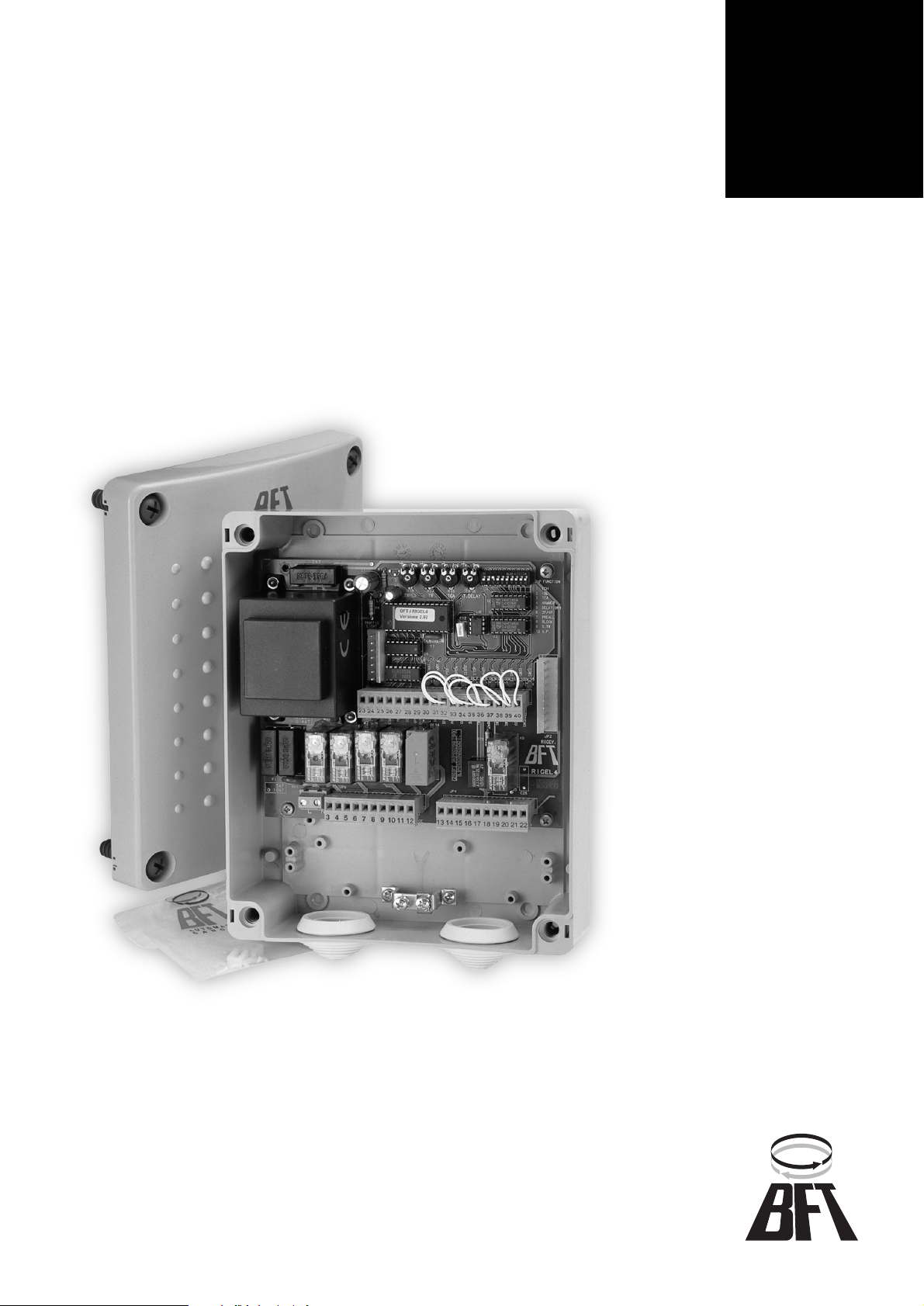
RIGEL 4
D811208 02-09-98 Vers. 02
CONTROL UNIT
Page 2

420
D811208_02
RIGEL 4
RIGEL 4
Thank you for buying this product, our company is sure that you will be more
than satisfied with the product’s performance.
The product is supplied an “INSTRUCTION MANUAL” which provides
important information about safety, installation, operation and maintenance.
This product complies with the recognised technical standards and safety
regulations. We declare that this product is in conformity with the following
European Directives: 89/336/EEC and 73/23/EEC (amended by RL 91/263/
EEC, 92/31/EEC and 93/68/EEC).
IMPORTANT NOTE
For wiring and installation operations, refer to
the current standards and follow the main technical principles
ensuring good performance.
1) General outline
This control unit with microprocessor has been designed to control one or
two motors with a power up to 375 W.
The control unit is equipped with Dip-switches and trimmers which allow the
configuration and calibration of the unit respectively. The functions of the
Dip-switches and trimmers as well as the effects generated by the alteration
to the initial setting are described in the following paragraphs while their
arrangement on the board is shown in the diagram of figure 1.
To facilitate maintenance and replacement operations, the board features
a removable terminal board with 40 terminals. The wiring diagram of the
board is shown in figure 2.
To facilitate installation operations, the board is supplied with a series of
pre-wired jumpers.
The jumpers refer to the following terminals: 31-33, 32-33, 33-34, 35-36,
36-37, 38-39, 39-0.
On request, the SSR4 board controlling two traffic lights can be fitted to the
board; the operation and specifications of the traffic light board are contained in the relevant specific section while the wiring diagram and a possible arrangement is shown in figure 3.
Rigel 4 can be completed with an additional SPL board (figure 4) and an
automatic thermostat for motor pre-heating. For wiring diagram, see fig. 5.
The limit switch inputs for closing and opening manoeuvres are separate for
each motor.
If the sensing edge is activated, the special separate connection reverses
the movement direction for a period of 3 seconds (a subsequent command
continues the movement in the reverse direction).
A 12Vac electric lock can also be connected; the power excitation lasts
about 3 seconds.
The continuous duty EBP electric lock can be connected in parallel to the
blinker (230Vac).
A courtesy light output has been provided with a time range up to 90 seconds from the last command given.
2) Technical specifications
Mains power supply 230V±10% 50Hz (different voltages
available on request)
Mains insulation/low voltage > 2MOhm 500Vdc
Dielectric strength/low voltage 3750Vac per 1 minute
Motor output current 5A max
Motor relay switching current 15A
Max. motor power 1 motor 375W, 2 motors 375W + 375W
Courtesy light Max 150W time set up to 90 seconds
from last command
Power supply for accessories 24Vac (0.5A maximum absorption)
Electric lock output 12Vac (2A maximum absorption)
Gate-open warning light 24Vac 3W max
Blinker 230V 40W max
Fuses see figure 1
3) Terminal board connection
JP1
1-2 Power supply 230Vac±10%, 50-60Hz (1 phase, 2 neutral).
JP6
3-4-5 Connection motor 1 (may be delayed in opening); terminal 4-5
phase and capacitor, terminal 3 neutral.
6-7-8 Connection motor 2 (may be delayed in closing); terminal 7-8
phase and capacitor, terminal 6 neutral.
9-10 Output for 230Vac flashing beacon (40W max) and for electronic
lock EBP 230Vac.
11-12 Courtesy light 230Vac (150W max) delayed for 90s after the last
operation.
JP4
13-14 Gate open warning light 24V (3W max).
15-16 24Vac output for photocells etc. (6W max, 25mA).
17-18 Output for 12Vac lock (2A max).
19-20 Antenna input (19 signal, 20 braiding).
21-22 Output of second radio channel (if 2nd channel receiver installed).
JP5
23-24 Start command (n.o.), START I for traffic light.
24-25 Start command (n.o.), START E for traffic light.
26-27 Pedestrian gate - start command
28-30 Open command (n.o.)
29-30 Close command (n.o.)
31-33 Stop command (n.c.)
32-33 Photocell input / safety circuit (n.c.)
33-34 Second safety circuit. Safety edge.
35-36 Open limit switch motor 1 (n.c.)
36-37 Close limit switch motor 1 (n.c.)
38-39 Open limit switch motor 2 (n.c.)
39-40 Close limit switch motor 2 (n.c.)
4) Functioning logic
The configuration of the control unit Rig el 4 with microprocessor is obtained
by means of the Dip-switches.
Dip-switch 1 Photocells (FCH)
ON - Inhibits the operation of the photocell during the opening movement
and immediately reverses the movement direction in the closing phase as
soon as an obstacle is detected by the photocell.
OFF - When the photocell detects an obstacle and the gate is closing, the
movement of the gate is immediately stopped; as soon as the obstacle has
been removed, the gate opens. If an obstacle is detected by the photocell
when the gate is opening, it stops immediately; as soon as the obstacle has
been removed, the gate completes the opening stroke.
Dip-switch 2 Impulse blocking device (IBL)
ON - The start impulse has no effect on opening.
OFF - The start impulse on opening causes the stop of the gate (Dip 6 OFF)
or the reverse (Dip 6 ON).
Dip-switch 3 Automatic closing (TCA)
ON - Carries out the automatic closing of the gate after a dwell time set on
the TCA trimmer. The automatic closing is activated when: the gate reaches
the opening end of stroke position, the working time on opening has elapsed,
the gate is stopped during the opening phase by a start impulse.
OFF - Inhibits the automatic closing.
Dip-switch 4 Ram blow (HAMMER)
ON - Before opening the gate, it pushes for about 2 seconds on closing. This
permits an easier release of the electric lock.
OFF - Inhibits the ram blow.
Dip-switch 5 Motor 1 opening delay (DELAY OPEN)
ON - Motor 1 starts with a delay of about 3 seconds on opening.
OFF - Motor 1 starts with a delay of about 0.5 seconds on opening.
Dip-switch 6 2 or 4-step logic (2P/4P)
ON - When a start impulse is given while the gate is moving, the movement
direction will be inverted (2 step logic).
OFF - When a start impulse is given while the gate is moving, the gate will
stop; a subsequent impulse will cause the inversion of the movement direction (4 step logic). Note: the start impulse has no effect when the Dip 2 is
OFF during the opening phase.
Dip-switch 7 Pre-alarm (PREAL)
ON - The blinker lights up about 3 seconds prior to motor start.
OFF - The blinker lights up as soon as the motors start.
Dip-switch 8 Block persistence (BLOCK)
ON - If the motors remain still in the complete opening or closing position
for more than one hour, they are pushed for about 3 seconds in the end of
stroke direction. This function is performed every hour.
OFF - Inhibits the block persistence function.
Note: In the case of oil-hydraulic motors, this function is used to compensate
for any possible oil volume decrease due to a temperature decrease during
long pauses (for example during the night) and to keep the grease slightly
heated in all the electromechanical actuators for swing gates.
WARNING: Do not use this function for sliding gates or without appropriate
mechanical blocks.
Dip-switch 9 Reduced or standard working time range (S.TW)
ON - Working time TW between 1‚ 40 seconds (TW.PED from 1 to 20 seconds).
OFF - Working time TW between 30‚ 180 seconds (TW.PED from 15 to 90
seconds).
Dip-switch 10 Gate-open/close control (U.P.)
Operates on the signals connected to the terminals 28-29.
ON - Hold-to-run operation: the manoeuvre lasts for as long as the control
key is pressed.
OFF - Separate gate-open/close automatic control: one impulse opens the
gate if closed and vice versa.
CONTROL UNITS
CONTROL UNITS
Page 3

421
D811208_02
5) Functions controlled by the trimmers
TW.PED Adjusts the working time of the pedestrian access gate (motor
2) or the partial working time of a sliding gate with both pedestrian and vehicular access.
TW Adjusts the working time both during opening and closing.
TCA Adjusts the dwell time after which the gate re-closes automati-
cally.
T.DELAY Adjusts the delay time on closing of motor 2.
6) LED functions
The Rigel 4 control unit is equipped with a series of LEDs which detect any
system malfunctions.
LINE (DL1) Stays on in the presence of the mains supply and when
the fuse F2 is in perfect working order.
START I (DL2) Lights up when an internal start command is given.
START E (DL3) Lights up when an external start command is given or
when the first channel of the receiver is activated.
PED (DL4) Lights up when a start command for the pedestrian ac-
cess is given.
OPEN (DL5) Lights up when a manual opening control is given.
CLOSE (DL6) Lights up when a manual closing control is given.
STOP (DL7) Switches off when a block command is given.
PHOT (DL8) Switches off when the photocells are not aligned that is
when obstacles are detected.
BAR (DL9) Switches off when the sensitive edge is activated.
SWO1 (DL10) Switches off when the gate (motor 1) reaches its com-
plete opening position provided that it is equipped with
a limit switch.
SWC1 (DL11) Switches off when the gate (motor 1) reaches its com-
plete closing position provided that it is equipped with a
limit switch.
SWO2 (DL12) Switches off when the gate (motor 2) reaches its com-
plete opening position provided that it is equipped with
a limit switch.
SWC2 (DL13) Switches off when the gate (motor 2) reaches its com-
plete closing position provided that it is equipped with a
limit switch.
(DL14) Direction indicator LED: lights up when the gate is clos-
ing.
M1 (DL15) Lights up when motor 1 is activated (on opening or clos-
ing).
M2 (DL16) Lights up when motor 2 is activated (on opening or clos-
ing).
After having connected the control unit to the mains with the jumpers prewired between the terminals, see figure 2, make sure that it works perfectly
by checking if the following LEDs light up: LINE, STOP, PHOT, BAR, SWO1,
SWC1, SWO2, SWC2.
This fast check is recommended before installation in order to discover any
malfunctions of the control unit.
7) SSR4 traffic light board (on request)
This board is only supplied for the Rigel 4 control unit.
SSR4 permits to manage two traffic lights with two lights each, one usually
red and one green, which operate according to the usual logic for automatic
gates. In addition, some other options are available that can be set using
the Dip-switches provided in the SSR4 board.
The gate as well as the traffic light can be controlled by means of two commands:
• internal START (given when the gate is closed) which not only opens
the gate but also switches on the red light on the outside and the green
one on the inside when the gate is open.
• ext ernal START (given when the gate is closed) which not only opens
the gate but also switches on the red light on the inside and the green
one on the outside when the gate is open.
During the opening and closing manoeuvres the two red lights are illuminated.
IMPORTANT NOTE
Provide signals inviting to limit the speed and
to proceed slowly.
For a correct command sequence of the traffic light system, observe the
following procedures:
• Position the traffic light 2 inside with respect to the gate and the traffic
light 1 outside the gate (see figure 3).
• Activate the functions BLI, 2-step logic and pre-alarm (Dip 2, Dip 6,
Dip 7 all to ON) provided on Rigel 4.
• The only command to gain access from the outside must be the external START (already present on the first channel of the receiver).
• For installations with traffic lights not visible from each other it is
recommended to use the special microprocessor of Rig el 4 in which the
function of the Dip 2 of Rigel 4 becomes:
ON- Impulse blocking device active on opening.
OFF- Impulse blocking device active on opening and during the TCA
phase (if TCA on).
Terminal board connections:
1) phase
2) red light of traffic light 1
3) red light of traffic light 2
4) green light of traffic light 1
5) green light of traffic light 2
Dip-switch 1 Inhibits the blinking function at movement start
ON - Inhibits the blinking function at movement start
OFF - Activate the blinking function at movement start (operation time 5
sec).
Dip-switch 2 Permanent red light with gate closed
ON - Activates the red lights, when the gate is closed
OFF - Switches off the lights when the gate is closed.
Signals provided by the board:
Red and green LEDs for traffic light 1 and traffic light 2.
Luminous signal for each traffic light:
Green light: access permitted - fixed red light: access not permitted - Flashing red light: gate movement start; access not permitted.
N.B.: The movement reverse on closing does not enable the green light;
before giving the Start command it is necessary to wait until the gate is
completely closed.
RIGEL 4
RIGEL 4
CONTROL UNITS
CONTROL UNITS
Page 4

422
D811208_02
RIGEL 4
RIGEL 4
CONTROL UNITS
CONTROL UNITS
Fig. 1
5A/F (230V)
10A/F (110V)
0.2A/T (230V)
F1 F2
Fuse 2A/T
M1
DL15
0.4A/T (110V)
JP1
F3
DL1
+- +- +- +-
TW.PED
TW TCA T.DELAY
LINE
TRAFFIC
BFT / RIGEL4
LIGHT JP3
START I
DL2
DL3
DL4
DL5
DL6
DL7
DL8
PHOT
STOP
CLOSE
OPEN
PED
START E
JP5
23 24 25 26 27 28 29 30 31 32 33 34 35 36 37 38 39 40
M2
DL16 DL14
JP4JP6
ON
12345678910
SWC1
SWO1
DL9
BAR
DL10
DL11
DL12
DIP function
1 FCH
2 IBL
3 TCA
4 HAMMER
5 DELAY OPN
6 2P/4P
7 PREALL
8 BLOCK
9 S.TW
10 U.P.
SWC2
SWO2
DL13
RIGEL4
JP2
RICEV.
1
2
3 4 5 6 7 8 9 101112 13141516171819202122
Fig. 2
JP1 JP6 JP4 JP5
12
LN
3124 5 6 7 8 9 10 11 13 2214 15 16 17 18 19 20 21 23 3324 25 26 27 28 29 30 31 32
PED
M1 M2
230V
150W max.
24V
3W max.
SCA
24Vac
Lock
12Vac
ANT. CH2
START I
NO
COM
COM
START E
NO NO NO NO NC
JP5
40W max.
EBP
35 36 37 38 39 40
COM
SWC1
SWO1
SWO2
NC NC NC NC
Fig. 3
LINE
R1 R2
G1 G2
1
2
3
4
5
Semaforo 1 esterno
Outside traffic light 1
Feu 1 extrieur
Ampel 1 Aussen
Semforo 1 externo
Semaforo 2 interno
Inside traffic light 2
Feu 2 intrieur
Ampel 2 Innen
Semforo 2 interno
R1
R2
G1
G2
1
2
3
4
5
JP2
COM
OPEN
CLOSE
COM
SWC2
K2
DIP Function
1 Blinking
2 Red light in close position
STOP
NC
K1
PHOT
DL3
DL1
DL4
DL2
SSR4
COM
T.L.1
T.L.2
34
BAR
NC
NEUTRE
JP1
1
2
Page 5

423
D811208_02
RIGEL 4
RIGEL 4
CONTROL UNITS
CONTROL UNITS
Fig. 4 Fig. 5
1
2
3
4
5
6
Cavallotto di messa a terra
U-link for earth connection
Crampillon de mise la terre
Erdanschlussklemmen
Perno de U de toma de tierra
Fig. 6
Scatola grande
Big box
Bote grande
Gro§es Gehuse
Caja grande
SPL
M1
LN
12 3124 5 6 7 8 9 10 11
M2
1
2 3 4 5 6
24Vac
RIGEL 4
SPLSPL
Scatola piccola
Small box
Bote petite
Kleines Gehuse
Caja pequea
SSR4
RIGEL 4
SSR4
Disponibilit di raccordi tubo - cassetta:
CRTR (raccordo con tubo rigido)
CRTL (raccordo con guaina flessibile)
Available couplings connecting the pipes to the box:
CRTR (coupling with rigid pipe)
CRTL (coupling with flexible sheath)
Disponibilit de raccords tube - bote:
CRTR (raccord avec tube rigide)
CRTL (raccord avec tuyau souple)
Erhltliche Rohrverschraubungen fr Steuerungsgehuse:
CRTR (Verbindungsstck fr starres Rohr)
CRTL (Verbindungsstck fr flexibles Rohr)
Disponibilidad de uniones tubo - caja:
CRTR (unin con tubo rgido)
CRTL (unin con vaina flexible)
RIGEL 4
Cavallotto di messa a terra
U-link for earth connection
Crampillon de mise la terre
Erdanschlussklemmen
Perno de U de toma de tierra
 Loading...